EP3599524A1 - Installation technique modulaire - Google Patents
Installation technique modulaire Download PDFInfo
- Publication number
- EP3599524A1 EP3599524A1 EP18184975.3A EP18184975A EP3599524A1 EP 3599524 A1 EP3599524 A1 EP 3599524A1 EP 18184975 A EP18184975 A EP 18184975A EP 3599524 A1 EP3599524 A1 EP 3599524A1
- Authority
- EP
- European Patent Office
- Prior art keywords
- module
- technical system
- modular technical
- modular
- automation
- Prior art date
- Legal status (The legal status is an assumption and is not a legal conclusion. Google has not performed a legal analysis and makes no representation as to the accuracy of the status listed.)
- Withdrawn
Links
Images


Classifications
-
- G—PHYSICS
- G05—CONTROLLING; REGULATING
- G05B—CONTROL OR REGULATING SYSTEMS IN GENERAL; FUNCTIONAL ELEMENTS OF SUCH SYSTEMS; MONITORING OR TESTING ARRANGEMENTS FOR SUCH SYSTEMS OR ELEMENTS
- G05B19/00—Programme-control systems
- G05B19/02—Programme-control systems electric
- G05B19/04—Programme control other than numerical control, i.e. in sequence controllers or logic controllers
- G05B19/042—Programme control other than numerical control, i.e. in sequence controllers or logic controllers using digital processors
- G05B19/0426—Programming the control sequence
Definitions
- the invention relates to a module for a modular technical system according to claim 1. Furthermore, the invention relates to a modular technical system according to claim 5. In addition, the invention relates to a method for the automated integration of a module into a modular technical system according to claim 8 and the use of a module for operating a modular technical system according to claim 9.
- Flexibility and scalability are playing an increasingly important role in process engineering systems. On the one hand, this means that parts of the system are developed separately as small units and then integrated into larger system parts in order to carry out special production steps (flexibility). On the other hand, individual system parts can be flexibly added to a larger system in order to increase production (scalability).
- MTP Module Type Package
- Modularization concepts such as MTP require engineering steps such as reading out certain interfaces and typing them before starting up the production system Plant pictures for the individual modules.
- plant images have to be created manually, automation programs controlled and process images integrated for operation and monitoring.
- the previous steps have to be validated.
- the project planning of the entire production system is therefore complex, time-consuming and error-prone.
- FIG. 1 the integration of a first production module 1 and a second production module 2 into a control system 3 of a production system 3 is shown as an example.
- the first production module 1 comprises devices 4a, 4b to be controlled, an input / output system 5 and an active automation station 6.
- a first device 4a to be controlled is connected directly to the automation station 6 by means of Profibus®-DP (decentralized periphery).
- a second device 4b to be controlled is connected to the input / output system 5 via a HART connection (Highway Addressable Remote Transducer).
- the Input / Output System 5 can be a SIMATIC ET 200M from SIEMENS, for example.
- the input / output system 5 is designed to transmit the data received from the second device 4b to be controlled to the automation station 6 via the Profibus connection (or to receive it in the opposite direction and to the second device 4b to be controlled) transfer).
- the automation station 6 actively carries out control functions for the first production module 1. As a rule, it comprises at least one power supply, a central processing unit (CPU) and communication modules. Automation station 6 can be a SIMATIC S7-400 from SIEMENS, for example.
- the second production module 2 also includes devices 7a, 7b to be controlled, an input / output system 8 and an active automation station 9.
- the second device 7b has a Profibus-PA (process automation) connection and therefore requires an interface module 10 that enables communication between the Profibus-PA and the Profibus-DP connection.
- Profibus-PA process automation
- the two automation stations 6, 9 are connected via a system bus 11 to an ES server (engineering station) 12 and an OS server 13 (operator station).
- the plant bus 11 can be, for example, Industrial Ethernet.
- the servers 12, 13 are connected to display and operating means 15a, 15b by means of a terminal bus 14.
- each production module 1, 2 has its own active automation 6, 9.
- the production modules 1, 2 represent "black boxes", which are generally identified by means of an MTP interface. This interface has to be integrated into the entire production plant by appropriate engineering, which is a complex process.
- the invention has for its object to provide a module for a modular technical system that can be automated and easily integrated into the system without consuming excessive resources.
- a module according to the invention for a modular technical system of the type described in the introduction, in particular a process system, has at least one actuator or sensor and has a communication interface.
- the module according to the invention is characterized in that it has no component for controlling the at least one actuator or sensor.
- information is stored in the module that enables a device outside the module to operate the module in the modular technical system.
- the modular technical system can be a system from the process industry such as a chemical, pharmaceutical, petrochemical or a system from the food and beverage industry. This also includes all systems from the production industry, plants in which e.g. Cars or goods of all kinds are produced.
- Technical systems that are suitable for carrying out the method according to the invention can also come from the field of energy generation. Wind turbines, solar systems or power plants for energy generation are also included in the term technical system.
- control system each have a control system or at least a computer-aided module for controlling and regulating the ongoing process or production.
- Part of the control system or control module or a technical system is usually at least one database or an archive in which historical data are stored.
- module is understood to mean a device which has at least one actuator or sensor.
- the module has at least one communication interface, which serves to control the module from the outside or to transmit data generated within the module to the outside.
- Communication takes place, for example, with the control system of the modular technical system or with other modules within the system.
- Communication can also take place in or to a cloud environment.
- a cloud environment is understood to mean a computer network with online-based storage and server services, which is usually also referred to as a cloud or cloud platform.
- the data stored in the cloud environment is accessible online, so that the modular technical system usually has access to a central data archive in the cloud via the Internet.
- the module has no component for controlling the at least one actuator or sensor. It is therefore a purely passive module. Without the interconnection of the module with another module or with the control system of the modular technical system, the module according to the invention is not able to perform technical tasks in the technical system. However, information is stored in the module that enables a device outside the module to operate the module in the modular technical system. Such a device can be, for example, another (active) module or a control system with a corresponding control architecture. To operate the module, at least one automation program and one HMI (Human Machine Interface) are usually required.
- HMI Human Machine Interface
- the module can be fully automated integrated into the modular technical system.
- the (passive) module according to the invention advantageously does not have to have any computing capacities. Scalability of the modular technical system is also significantly easier through the use of one or more modules according to the invention, since the (passive) modules can also be easily integrated into the modular technical system in a "plug & play" process.
- the information preferably represents a unique identifier of the module, by means of which the device outside the module can extract additional data required for operating the module from a database outside the module.
- the passive module provides a clear and unmistakable identification when connected to the modular technical system, which enables the external device (active module or control system) to carry out the control or automation tasks for the passive module.
- the information stored in the module can include all the data required to operate the module.
- An advantage of this development of the module according to the invention is that no separate database is required. For example, the database may not always be 100% available. The integration of the passive module into the modular technical system would be unnecessarily delayed or made more difficult.
- the data required to operate the module can be in the form of a continuous function chart, which further simplifies the integration of the module due to the standardized functional descriptions of the module.
- a modular technical system which is in particular a process system.
- This system has at least one (passive) module as explained previously.
- the modular technical system has at least one second module, which likewise has at least one actuator or sensor and has a communication interface.
- the second module comprises a control component for controlling the at least one actuator or sensor, information being stored in the second module, which enables the control component to operate the second module in the technical system.
- the modular technical system according to the invention comprises at least one previously explained passive module and at least one active module.
- the control component of the second module is advantageously designed and provided to operate the first module by means of the information stored in the first module.
- the system can have a control device outside the at least one first module and the at least one second module, which is designed and provided to operate the first module by means of the information stored in the first module.
- the module explained above can be used to operate a modular technical system, in particular a process system.
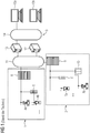
- FIG 2 a schematic diagram of a modular technical system 16 according to the invention is shown.
- the system 16 comprises a first, active module 17, a second, passive module 18 and a third, passive module 19.
- the three modules 17, 18, 19 are connected to a control system 20 of the modular technical system 16.
- the first, active module 17 comprises devices 21a, 21b to be controlled, an input / output system 22 and an active automation station 23.
- a first device 21a to be controlled is connected directly to the automation station 23 by means of Profibus®-DP (decentralized periphery).
- a second device 21b to be controlled is connected to the input / output system 22 via a HART connection (Highway Addressable Remote Transducer).
- the input / output system 22 can be, for example, a SIMATIC ET 200M from SIEMENS.
- the input / output system 22 is designed to transmit the data received from the second device 21b to be controlled to the automation station 23 via the Profibus connection (or to receive it in the opposite direction and to the second device 21b to be controlled) transfer). Since the first module 17 has its own automation station 23, this is referred to as an active module 17.
- the second module 18 comprises devices 24 to be controlled (only one of them is shown in FIG FIG 2 ) and an expanded input / output system 25.
- the module 18 has no automation station.
- the second module 18 requires the functionality of an additional automation or control device 26 located outside the second module 18. This is therefore referred to as a passive module 18.
- the third module 19 is constructed identically to the second module 18 and comprises devices 27 to be controlled (only one of which is in FIG 2 ) and also an expanded input / output system 28.
- the automation station 23 of the first, active module 17 and the additional automation or control device 26 are via a system bus 29 with an ES server (engineering station) 30 and an OS server 31 (operator station) of the control system 20 of the modular technical system 16 connected.
- the plant bus 11 can be, for example, Industrial Ethernet.
- the servers 30, 31 are connected to display and operating means 33a, 33b by means of a terminal bus 32.
- the process of coupling the passive modules 18, 19 with the active module 17 or with the control system 20 of the modular technical system 16 takes place in several steps: First, a communication link is established between the additional automation or control device 26 via Profibus® DP. The information required for the operation of the modules 18, 19 is then read from the extended input / output modules 25, 28. Finally, the information is integrated into automation of the additional automation or control device 26.
- the automation or control device 26 (referred to as "Automation System") of the control system 20 is controlled via the OS server 31.
- the automation or control device 26 reads an automation program 34 which is stored on the extended input / output modules 25, 28 of the two passive modules 18, 19.
- the automation program 34 is stored in the form of a CFC (Continuous Function Chart) and uses a certain number of automation types 35 (eg type "controller", type "valve” etc.).
- the automation program 34 additionally contains associated operating and monitoring descriptions (referred to as “passive package” 36) and interface information 37 (referred to as “interface description", for example with which data structure the passive modules 18, 19 must be addressed).
- the associated operating and observation descriptions 36 in turn comprise a certain number of system images 38 (referred to as “Operation Display Description").
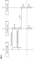
- FIG 4 an associated flowchart of the integration of the passive modules 18, 19 in the control system 20 of the modular technical system 16 is shown.
- a first step 39 the automation or control device 26 first loads the automation program 34 of the modules 18, 19.
- the automation program or its description (for example in the form of a CFC) is loaded into the automation or control device 26 integrated.
- the automation or control device 26 then loads the system images 38 from the modules 18, 19 in a third step 41 and transmits them to the OS server 31 of the control system 20 in a fourth step 42.
- a fifth step 43 the OS server 31 generates the necessary user interface during the runtime of the modular technical system.
- steps 44, 45 which run in parallel, the automation of the passive modules 18, 19 is carried out and the operating and monitoring station is operated on the OS server 31 in order to monitor the automation of the passive modules 18, 19.
- the pre-configured passive modules 18, 19 can be fully automatically integrated into the system 16 during the runtime of the modular technical system 16. This makes the flexibility of the system 16 clear increase. In addition, the time required for engineering the individual modules 18, 19 is reduced, since these can be configured autonomously by the other parts of the system 16.
Landscapes
- Physics & Mathematics (AREA)
- General Physics & Mathematics (AREA)
- Engineering & Computer Science (AREA)
- Automation & Control Theory (AREA)
- Control By Computers (AREA)
Priority Applications (1)
| Application Number | Priority Date | Filing Date | Title |
|---|---|---|---|
| EP18184975.3A EP3599524A1 (fr) | 2018-07-23 | 2018-07-23 | Installation technique modulaire |
Applications Claiming Priority (1)
| Application Number | Priority Date | Filing Date | Title |
|---|---|---|---|
| EP18184975.3A EP3599524A1 (fr) | 2018-07-23 | 2018-07-23 | Installation technique modulaire |
Publications (1)
| Publication Number | Publication Date |
|---|---|
| EP3599524A1 true EP3599524A1 (fr) | 2020-01-29 |
Family
ID=63035920
Family Applications (1)
| Application Number | Title | Priority Date | Filing Date |
|---|---|---|---|
| EP18184975.3A Withdrawn EP3599524A1 (fr) | 2018-07-23 | 2018-07-23 | Installation technique modulaire |
Country Status (1)
| Country | Link |
|---|---|
| EP (1) | EP3599524A1 (fr) |
Citations (4)
| Publication number | Priority date | Publication date | Assignee | Title |
|---|---|---|---|---|
| US5901323A (en) * | 1990-12-11 | 1999-05-04 | Fisher Controls International, Inc. | Process controller with interchangeable individual I/O units |
| DE10208530A1 (de) * | 2002-02-27 | 2003-09-18 | Moeller Gmbh | Betriebseinheit, Peripheriegerät und Verfahren zum Betrieb eines Peripheriegeräts |
| EP2801880A2 (fr) * | 2013-05-10 | 2014-11-12 | Rolls-Royce plc | Système de surveillance d'équipement |
| EP3021179A1 (fr) * | 2014-11-14 | 2016-05-18 | Schneider Electric Automation GmbH | Procede de raccordement d'un appareil integre a une unite de commande |
-
2018
- 2018-07-23 EP EP18184975.3A patent/EP3599524A1/fr not_active Withdrawn
Patent Citations (4)
| Publication number | Priority date | Publication date | Assignee | Title |
|---|---|---|---|---|
| US5901323A (en) * | 1990-12-11 | 1999-05-04 | Fisher Controls International, Inc. | Process controller with interchangeable individual I/O units |
| DE10208530A1 (de) * | 2002-02-27 | 2003-09-18 | Moeller Gmbh | Betriebseinheit, Peripheriegerät und Verfahren zum Betrieb eines Peripheriegeräts |
| EP2801880A2 (fr) * | 2013-05-10 | 2014-11-12 | Rolls-Royce plc | Système de surveillance d'équipement |
| EP3021179A1 (fr) * | 2014-11-14 | 2016-05-18 | Schneider Electric Automation GmbH | Procede de raccordement d'un appareil integre a une unite de commande |
Non-Patent Citations (1)
| Title |
|---|
| WAGO: "DIMA - Dezentrale Intelligenz für modulare Anlagen", 14 December 2015 (2015-12-14), pages 1 - 8, XP055355896, Retrieved from the Internet <URL:http://www.dima-process.com/wp-content/uploads/2015/12/WHITEPAPER_Technische_Loesung_fuer_die_Automatisierung_modularer_Anlagen.pdf> [retrieved on 20170317] * |
Similar Documents
| Publication | Publication Date | Title |
|---|---|---|
| EP2789145B1 (fr) | Dispositif de commande d'au moins un appareil de terrain utilisé dans le domaine de l'automatisation | |
| EP1096348B1 (fr) | Intégration d'un appareil de commande sur site dans un système de commande d'une installation | |
| DE102010029952A1 (de) | Verfahren zum Integrieren von zumindest einem Feldgerät in ein Netzwerk der Automatisierungstechnik | |
| DE102010062266A1 (de) | Verfahren zur Realisierung von zumindest einer Zusatzfunktion eines Feldgeräts in der Automatisierungstechnik | |
| EP3876046A1 (fr) | Annotation de retour des sélections opérateur | |
| EP3623891A1 (fr) | Hiérarchies d'images pouvant être individualisées pour un système de conduite d'une installation technique | |
| EP3637205A1 (fr) | Déclenchement de l'image sur une station client de l'opérateur | |
| WO2016141998A1 (fr) | Dispositif et procédé pour produire une représentation numérique d'une entité physique | |
| DE102007059671A1 (de) | Verfahren zum Betreiben eines Systems aufweisend ein Feldgerät und ein Bediensystem | |
| DE102011005062A1 (de) | Verfahren zum Bereitstellen von Daten eines Feldgeräts | |
| EP3650970A1 (fr) | Procédé et dispositif de simulation assistée par ordinateur d'un système technique modulaire | |
| EP3861413B1 (fr) | Procédé pour établir une communication de réseau par opc ua | |
| EP1758001A2 (fr) | Procédé et système destinés à représenter la structure d' une installation d' automatisation sur un ordinateur | |
| EP3652595B1 (fr) | Procédé et système pour surveiller une installation de la technologie d'automatisation | |
| EP2557464A1 (fr) | Procédé destiné au fonctionnement d'un système d'automatisation | |
| EP3599524A1 (fr) | Installation technique modulaire | |
| EP1454201B1 (fr) | Systeme d'ingenierie et systeme d'automatisation | |
| WO2008077358A1 (fr) | Appareillage doté d'un appareil d'automatisation et d'un appareil de commande, et procédé d'exploitation d'un tel appareillage | |
| DE102007062398A1 (de) | Verfahren und Vorrichtung zur Integration eines Feldgeräts der Automatisierungstechnik in beliebige übergeordnete Steuerstrukturen | |
| DE102018131119A1 (de) | Integration mehrerer Anlagenmodule mit jeweils wenigstens einer prozesstechnischen Einheit zu einer modular aufgebauten Gesamtanlage | |
| LU500646B1 (de) | Technik zur Bereitstellung einer Diagnosefunktionalität für eine auf einer speicherprogrammierbaren Steuerung basierenden Anwendung | |
| DE102016121788A1 (de) | Konfiguration einer Automatisierungsanlage | |
| EP4124917A1 (fr) | Connexion pouvant être commandée entre les sources de données et les collecteurs de données dans une solution d'automatisation | |
| DE202021106310U1 (de) | Computerimplementiertes Prozessmodul | |
| DE102022204494A1 (de) | Datenverarbeitungssystem zur effizienten Kommunikation großer Datenmengen |
Legal Events
| Date | Code | Title | Description |
|---|---|---|---|
| PUAI | Public reference made under article 153(3) epc to a published international application that has entered the european phase |
Free format text: ORIGINAL CODE: 0009012 |
|
| AK | Designated contracting states |
Kind code of ref document: A1 Designated state(s): AL AT BE BG CH CY CZ DE DK EE ES FI FR GB GR HR HU IE IS IT LI LT LU LV MC MK MT NL NO PL PT RO RS SE SI SK SM TR |
|
| AX | Request for extension of the european patent |
Extension state: BA ME |
|
| STAA | Information on the status of an ep patent application or granted ep patent |
Free format text: STATUS: THE APPLICATION IS DEEMED TO BE WITHDRAWN |
|
| 18D | Application deemed to be withdrawn |
Effective date: 20200730 |