EP2801438A1 - Method for measuring reference point of inclined rotating table in wire electric discharge machine and measuring jig - Google Patents
Method for measuring reference point of inclined rotating table in wire electric discharge machine and measuring jig Download PDFInfo
- Publication number
- EP2801438A1 EP2801438A1 EP14166431.8A EP14166431A EP2801438A1 EP 2801438 A1 EP2801438 A1 EP 2801438A1 EP 14166431 A EP14166431 A EP 14166431A EP 2801438 A1 EP2801438 A1 EP 2801438A1
- Authority
- EP
- European Patent Office
- Prior art keywords
- section
- spherical surface
- rotating table
- measuring
- discharge machine
- Prior art date
- Legal status (The legal status is an assumption and is not a legal conclusion. Google has not performed a legal analysis and makes no representation as to the accuracy of the status listed.)
- Granted
Links
- 238000000034 method Methods 0.000 title claims description 36
- 238000005259 measurement Methods 0.000 abstract description 17
- 238000003754 machining Methods 0.000 description 12
- 239000004020 conductor Substances 0.000 description 4
- 239000000523 sample Substances 0.000 description 3
- NJPPVKZQTLUDBO-UHFFFAOYSA-N novaluron Chemical compound C1=C(Cl)C(OC(F)(F)C(OC(F)(F)F)F)=CC=C1NC(=O)NC(=O)C1=C(F)C=CC=C1F NJPPVKZQTLUDBO-UHFFFAOYSA-N 0.000 description 2
- 238000003466 welding Methods 0.000 description 2
Images


Classifications
-
- G—PHYSICS
- G01—MEASURING; TESTING
- G01B—MEASURING LENGTH, THICKNESS OR SIMILAR LINEAR DIMENSIONS; MEASURING ANGLES; MEASURING AREAS; MEASURING IRREGULARITIES OF SURFACES OR CONTOURS
- G01B5/00—Measuring arrangements characterised by the use of mechanical techniques
- G01B5/004—Measuring arrangements characterised by the use of mechanical techniques for measuring coordinates of points
-
- B—PERFORMING OPERATIONS; TRANSPORTING
- B23—MACHINE TOOLS; METAL-WORKING NOT OTHERWISE PROVIDED FOR
- B23H—WORKING OF METAL BY THE ACTION OF A HIGH CONCENTRATION OF ELECTRIC CURRENT ON A WORKPIECE USING AN ELECTRODE WHICH TAKES THE PLACE OF A TOOL; SUCH WORKING COMBINED WITH OTHER FORMS OF WORKING OF METAL
- B23H11/00—Auxiliary apparatus or details, not otherwise provided for
- B23H11/003—Mounting of workpieces, e.g. working-tables
-
- G—PHYSICS
- G01—MEASURING; TESTING
- G01B—MEASURING LENGTH, THICKNESS OR SIMILAR LINEAR DIMENSIONS; MEASURING ANGLES; MEASURING AREAS; MEASURING IRREGULARITIES OF SURFACES OR CONTOURS
- G01B21/00—Measuring arrangements or details thereof, where the measuring technique is not covered by the other groups of this subclass, unspecified or not relevant
- G01B21/02—Measuring arrangements or details thereof, where the measuring technique is not covered by the other groups of this subclass, unspecified or not relevant for measuring length, width, or thickness
- G01B21/04—Measuring arrangements or details thereof, where the measuring technique is not covered by the other groups of this subclass, unspecified or not relevant for measuring length, width, or thickness by measuring coordinates of points
- G01B21/042—Calibration or calibration artifacts
-
- G—PHYSICS
- G01—MEASURING; TESTING
- G01B—MEASURING LENGTH, THICKNESS OR SIMILAR LINEAR DIMENSIONS; MEASURING ANGLES; MEASURING AREAS; MEASURING IRREGULARITIES OF SURFACES OR CONTOURS
- G01B21/00—Measuring arrangements or details thereof, where the measuring technique is not covered by the other groups of this subclass, unspecified or not relevant
- G01B21/02—Measuring arrangements or details thereof, where the measuring technique is not covered by the other groups of this subclass, unspecified or not relevant for measuring length, width, or thickness
- G01B21/04—Measuring arrangements or details thereof, where the measuring technique is not covered by the other groups of this subclass, unspecified or not relevant for measuring length, width, or thickness by measuring coordinates of points
- G01B21/045—Correction of measurements
-
- G—PHYSICS
- G01—MEASURING; TESTING
- G01B—MEASURING LENGTH, THICKNESS OR SIMILAR LINEAR DIMENSIONS; MEASURING ANGLES; MEASURING AREAS; MEASURING IRREGULARITIES OF SURFACES OR CONTOURS
- G01B3/00—Measuring instruments characterised by the use of mechanical techniques
- G01B3/22—Feeler-pin gauges, e.g. dial gauges
-
- G—PHYSICS
- G01—MEASURING; TESTING
- G01B—MEASURING LENGTH, THICKNESS OR SIMILAR LINEAR DIMENSIONS; MEASURING ANGLES; MEASURING AREAS; MEASURING IRREGULARITIES OF SURFACES OR CONTOURS
- G01B3/00—Measuring instruments characterised by the use of mechanical techniques
- G01B3/30—Bars, blocks, or strips in which the distance between a pair of faces is fixed, although it may be preadjustable, e.g. end measure, feeler strip
- G01B3/303—Bars, blocks, or strips in which the distance between a pair of faces is fixed, although it may be preadjustable, e.g. end measure, feeler strip pre-adjustable, e.g. by means of micrometerscrew
-
- G—PHYSICS
- G01—MEASURING; TESTING
- G01B—MEASURING LENGTH, THICKNESS OR SIMILAR LINEAR DIMENSIONS; MEASURING ANGLES; MEASURING AREAS; MEASURING IRREGULARITIES OF SURFACES OR CONTOURS
- G01B5/00—Measuring arrangements characterised by the use of mechanical techniques
- G01B5/004—Measuring arrangements characterised by the use of mechanical techniques for measuring coordinates of points
- G01B5/008—Measuring arrangements characterised by the use of mechanical techniques for measuring coordinates of points using coordinate measuring machines
-
- B—PERFORMING OPERATIONS; TRANSPORTING
- B23—MACHINE TOOLS; METAL-WORKING NOT OTHERWISE PROVIDED FOR
- B23H—WORKING OF METAL BY THE ACTION OF A HIGH CONCENTRATION OF ELECTRIC CURRENT ON A WORKPIECE USING AN ELECTRODE WHICH TAKES THE PLACE OF A TOOL; SUCH WORKING COMBINED WITH OTHER FORMS OF WORKING OF METAL
- B23H2500/00—Holding and positioning of tool electrodes
- B23H2500/20—Methods or devices for detecting wire or workpiece position
-
- B—PERFORMING OPERATIONS; TRANSPORTING
- B23—MACHINE TOOLS; METAL-WORKING NOT OTHERWISE PROVIDED FOR
- B23H—WORKING OF METAL BY THE ACTION OF A HIGH CONCENTRATION OF ELECTRIC CURRENT ON A WORKPIECE USING AN ELECTRODE WHICH TAKES THE PLACE OF A TOOL; SUCH WORKING COMBINED WITH OTHER FORMS OF WORKING OF METAL
- B23H7/00—Processes or apparatus applicable to both electrical discharge machining and electrochemical machining
- B23H7/02—Wire-cutting
-
- B—PERFORMING OPERATIONS; TRANSPORTING
- B23—MACHINE TOOLS; METAL-WORKING NOT OTHERWISE PROVIDED FOR
- B23Q—DETAILS, COMPONENTS, OR ACCESSORIES FOR MACHINE TOOLS, e.g. ARRANGEMENTS FOR COPYING OR CONTROLLING; MACHINE TOOLS IN GENERAL CHARACTERISED BY THE CONSTRUCTION OF PARTICULAR DETAILS OR COMPONENTS; COMBINATIONS OR ASSOCIATIONS OF METAL-WORKING MACHINES, NOT DIRECTED TO A PARTICULAR RESULT
- B23Q2220/00—Machine tool components
- B23Q2220/004—Rotary tables
Definitions
- the present invention relates to a method for measuring a reference point of an inclined rotating table at the time of machining using the inclined rotating table by a wire electric discharge machine and a measuring jig used for the measurement.
- machining using an inclined rotating table has often been performed in wire electric discharge machines.
- machining a gear having an inclined surface such as a bevel gear
- using a wire electric discharge machine has often been performed in these years.
- a wire electrode can be ordinarily inclined only by up to about 45° in machining (taper machining) of an inclined surface using a wire electric discharge machine
- a bevel gear having a cone angle of, for example, 60° cannot be machined. It is thus common to attach a piece of work to a rotating table, incline the rotating table to near a cone angle of a bevel gear, and machine the piece of work with a wire electrode nearly vertical, when the piece of work is to be made into the bevel gear.
- a program is created using a point of intersection of a table center of the rotating table and a work-fixed surface as a reference point.
- the reference point defined at the time of the program creation coincide with a coordinate position on an actual machine, the coordinates of the reference point on the machine need to be measured.
- a table center of a rotating table is parallel to an X-Y plane
- reference coordinates on a machine are generally obtained by adjusting a jig in the shape of a round bar, called a test bar, such that the table center of the rotating table and a table center of the test bar coincide with each other, fixing the test bar to a work-fixed surface of the rotating table, and measuring the position of the test bar using a wire electrode or a probe.
- reference coordinates can be measured using a probe with a test bar as described earlier fixed in the same manner.
- an end face edge of a test bar needs to be a sharp edge.
- a measurement error occurs due to the difficulty of machining of a sharp edge and the difficulty of stable measurement of an edge.
- a wire electrode center is separate from a probe center in a general wire electric discharge machine, and a relative distance between the centers is difficult to accurately obtain. Even if a relative distance is accurately obtained, the relative distance needs to be obtained with each probe replacement. This increases the time for measurement work.
- an object of the present invention is to provide a measuring jig in a shape most suitable for reference point measurement using a contact sensing function of a wire electrode which a wire electric discharge machine generally has and a method for measuring a reference point on a table center of a rotating table using the measuring jig.
- the present invention relates to a measuring method for obtaining a reference point on a table center of an inclined rotating table in a wire electric discharge machine using a measuring jig.
- the wire electric discharge machine takes, as an X-axis, a direction of lateral movement on a horizontal plane of the wire electric discharge machine that machines a workpiece by moving a wire electrode and the workpiece relative to each other while supporting the wire electrode with upper and lower wire guides, takes, as a Y-axis, a direction of longitudinal movement on the horizontal plane which is perpendicular to the X-axis, and takes, as a Z-axis, a direction of vertically upward movement.
- a biaxial rotation unit is placed on a table of the wire electric discharge machine, and the biaxial rotation unit includes a first rotating table which rotates a work fixing section that fixes a workpiece and a second rotating table which rotates about an axis orthogonal to the rotating table and inclines a workpiece with respect to an X-Y plane.
- the measuring jig includes a fixed section for being fixed to the work fixing section, an arm section which is provided to stand on the fixed section, and a section to be measured which is provided at a distal end of the arm section and has a conductive spherical surface.
- a first aspect of a measuring method includes a step of measuring a height from a bottom surface of the fixed section of the measuring jig to a distal end of the spherical surface in the section to be measured of the measuring jig, a step of acquiring an angle of inclination of the second rotating table, a step of fixing the measuring jig to the work fixing section, a step of measuring a height from a table surface of the wire electric discharge machine to an upper end of the spherical surface, a step of bringing the wire electrode into contact with the spherical surface from opposing directions on a same straight line and measuring two points on the spherical surface, a step of bringing the wire electrode into contact with the spherical surface from a direction along a straight line which passes through a midpoint of the obtained two points and intersects the straight line at right angles and measuring one point on the spherical surface, a step of obtaining a center point position on the X-Y plane
- the step of acquiring the angle of inclination of the second rotating table can include a step of measuring positions of at least three points on a work-fixed surface of the second rotating table and a step of calculating angles which the work-fixed surface of the second rotating table forms with the Y-axis and the Z-axis from the measured positions of the at least three points.
- the step of acquiring the angle of inclination of the second rotating table may be a step of reading a value of an encoder which is mounted on the second rotating table.
- a second aspect of a measuring method includes a first step of measuring a height from a bottom surface of the fixed section of the measuring jig to a distal end of the spherical surface in the section to be measured of the measuring jig, a second step of fixing the measuring jig to the work fixing section, a third step of measuring a height from a table surface of the wire electric discharge machine to an upper end of the spherical surface, a fourth step of bringing the wire electrode into contact with the spherical surface from opposing directions on a same straight line and measuring two points on the spherical surface, a fifth step of bringing the wire electrode into contact with the spherical surface from a direction along a straight line which passes through a midpoint of the obtained two points and intersects the straight line at right angles and measuring one point on the spherical surface, a sixth step of obtaining a center point position on the X-Y plane of the spherical surface on the basis of
- a measuring jig for obtaining coordinates of a reference point on a table center of a rotating table for attaching a piece of work in a state inclined with respect to a horizontal plane of a table of a wire electric discharge machine includes a fixed section for being fixed to the rotating table, an arm section which is provided to stand on the fixed section, and a section to be measured which is provided at a distal end of the arm section and has a conductive spherical surface.
- a measuring jig having a shape most suitable for reference point measurement using a contact sensing function of a wire electrode which a wire electric discharge machine generally has and a method for measuring a reference point on a table center of a rotating table using the measuring jig can be provided.
- a first embodiment of a method for measuring a reference point of an inclined rotating table according to the present invention will first be described with reference to FIGS. 1 to 10 .
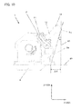
- a biaxial rotation unit 1 with an inclined rotating table which is placed on a table surface of a wire electric discharge machine will be described with reference to FIG. 1 .
- the biaxial rotation unit 1 shown in FIG. 1 includes a first rotating table which tilts in an inclination direction 4 and a second rotating table which rotates about an axis orthogonal to the inclination direction 4.
- Reference numeral 3 denotes a table center of the second rotating table.
- the biaxial rotation unit 1 is fixed to a table 8 (see FIG. 3 ) of the wire electric discharge machine by mounting a bolt in an elongated hole 7 which is provided in a basal section 6.
- the first rotating table is manually inclined in the inclination direction 4 in the biaxial rotation unit 1 in FIG. 1
- the first rotating table may be automatically inclined by a motor or the like.
- a work fixing section 2 is configured to be rotatable by 360°. In machining using a rotating table, a rotation center of a work fixing section is commonly used as reference coordinates. A point A which is a rotation center of the work fixing section is used as reference coordinates 5 in this embodiment.
- FIGS. 2A and 2B are an example of a measuring jig used in this embodiment.
- a measuring jig 10 includes a fixed section 11 for fixing the measuring jig 10 to the work fixing section 2, a columnar arm section 12 which is provided to stand on the fixed section 11, and a section 13 to be measured (a spherical surface section) which is provided at a distal end of the arm section 12 and has a conductive spherical surface.
- the arm section 12 is provided to stand perpendicular to the fixed section 11.
- a plurality of bolt holes 14 for fixing the measuring jig 10 to the work fixing section 2 that is a table of the second rotating table are provided in the fixed section 11.
- the measuring jig 10 can be fabricated by a method, such as welding a high-accuracy ball (e.g., a bearing ball) to the distal end of the cylindrical arm section 12.
- the whole of the measuring jig 10 may be formed of a conductive material. If only the section 13 to be measured having the spherical surface is formed of a conductive material, the section 13 to be measured having the spherical surface and the work fixing section 2 need to be electrically connected.
- FIG. 3 is a view for explaining a state in which the biaxial rotation unit 1 shown in FIG. 1 is installed on the table 8 of the machinery (wire electric discharge machine).
- the coordinates of the reference point on the table center 3 of the rotating table (work fixing section 2) in the biaxial rotation unit 1 can be obtained by using the measuring jig 10 shown in FIGS. 2A and 2B .
- a measuring jig (see FIGS. 11A and 11B ) which is different in shape from the measuring jig ( FIGS. 2A and 2B ) used in the first embodiment is used.
- the measuring jig used in this embodiment is different from the measuring jig 10 used in the first embodiment and is shaped such that a center of a section to be measured having a spherical surface cannot be brought onto a table center 3 of a rotating table (a work fixing section 2) of a biaxial rotation unit 1.
- a measuring jig 20 includes a fixed section 21 for being fixed to the rotating table (work fixing section 2) of the biaxial rotation unit 1, a columnar arm section 22 which is provided to stand on the fixed section 21, and a section 23 to be measured (a spherical surface section) which is provided at a distal end of the arm section 22 and has a conductive spherical surface.
- the arm section 22 is provided to stand inclined with respect to a direction perpendicular to the fixed section 21.
- a plurality of bolt holes 24 for fixing the measuring jig 20 to the rotating table (work fixing section 2) of the biaxial rotation unit 1 are provided in the fixed section 21.
- the measuring jig 20 can be fabricated by a method, such as welding a high-accuracy ball (e.g., a bearing ball) to the distal end of the cylindrical arm section 22.
- the whole of the measuring jig 20 may be formed of a conductive material. If only the section 23 to be measured having the spherical surface is formed of a conductive material, the section 23 to be measured having the spherical surface and the work fixing section 2 need to be electrically connected.
- angles ( ⁇ and ⁇ ) of the rotating table (work fixing section 2) of the biaxial rotation unit 1 need not be obtained in this embodiment. Note that calculation that determines a measurement start position at the time of obtaining a center of the section 23 to be measured having the spherical surface requires the angles ( ⁇ and ⁇ ) of the rotating table (work fixing section 2) of the biaxial rotation unit 1 if measurement automation using a program or the like is contemplated.
- the measuring jig 20 is attached to a work-fixed surface of the rotating table. Note that adjustment as in A-3 described earlier that brings the center of the section 23 to be measured having the spherical surface onto the table center of the rotating table is not performed.
- the coordinates of the reference point on the table center 3 of the rotating table (work fixing section 2) in the biaxial rotation unit 1 can be obtained in the same manner even with use of the measuring jig 20 as shown in FIGS. 11A and 11B .
- measurement automation based on a program or the like is possible.
- a wire electric discharge machine 50 is machinery which machines a piece of work (not shown) serving as a workpiece by producing discharge between a wire electrode 31 and the piece of work.
- the wire electric discharge machine 50 includes, on a pedestal 51, an X-axis saddle 54 which moves in an X-axis direction by a ball screw 53 which an X-axis motor 52 drives and includes, on the X-axis saddle 54, a Y-axis saddle 57 which moves in a Y-axis direction by a ball screw 56 which a Y-axis motor 55 drives.
- a work tank 58 which incorporates the table 8 where the biaxial rotation unit 1 is to be placed is fixed on the Y-axis saddle 57.
- a column 60 is made to stand perpendicularly on the pedestal 51.
- a lower arm 61 is horizontally attached to a side surface section of the column 60.
- a lower nozzle 62 and a lower wire guide 63 are attached to a distal end of the lower arm 61.
- the lower nozzle 62 and the lower wire guide 63 are located below the table 8.
- the column 60 includes a V-axis saddle 64 at an upper section.
- the V-axis saddle 64 moves in a V-axis direction by a ball screw 66 which a V-axis motor 65 drives.
- the V-axis direction is the same as the Y-axis direction.
- a U-axis table 67 is attached to the V-axis saddle 64.
- the U-axis table 67 moves in a U-axis direction by a ball screw 69 which a U-axis motor 68 drives.
- the U-axis direction is the same as the X-axis direction.
- An upper arm supporting member 70 is attached to the U-axis table 67.
- the upper arm supporting member 70 moves in a Z-axis direction by a ball screw 72 which a Z-axis motor 71 drives.
- An upper arm 73 is fixed to the upper arm supporting member 70.
- An upper nozzle 74 and an upper wire guide 75 are attached to an end section of the upper arm 73.
- the X-axis motor 52, the Y-axis motor 55, the Z-axis motor 71, the U-axis motor 68, and the V-axis motor 65 are connected to a control device 80 by power and signal lines 83, 84, 85, 86, and 87, respectively.
- the motors are supplied with motive power (electric power) from the control device 80 including an amplifier (not shown) and give and receive various signals to and from the control device 80.
- motive power electric power
- FIG. 13 that an X-axis and a U-axis are along a direction perpendicular to the sheet surface, that a Y-axis and a V-axis are along a horizontal direction of the sheet surface, and that a Z-axis is a vertical direction of the sheet surface.
- the control device 80 is a device which performs overall control of the wire electric discharge machine, includes an arithmetic unit, a display device, I/O interfaces for various signals, and an amplifier (not shown), and further includes a storage device 81 which stores various data.
- the arithmetic unit, the display device, the I/O interfaces for various signals, and the amplifier (not shown) are collectively called an arithmetic processing unit 82.
Abstract
Description
- The present invention relates to a method for measuring a reference point of an inclined rotating table at the time of machining using the inclined rotating table by a wire electric discharge machine and a measuring jig used for the measurement.
- In recent years, machining using an inclined rotating table has often been performed in wire electric discharge machines. For example, machining a gear having an inclined surface, such as a bevel gear, using a wire electric discharge machine has often been performed in these years. Since a wire electrode can be ordinarily inclined only by up to about 45° in machining (taper machining) of an inclined surface using a wire electric discharge machine, a bevel gear having a cone angle of, for example, 60° cannot be machined. It is thus common to attach a piece of work to a rotating table, incline the rotating table to near a cone angle of a bevel gear, and machine the piece of work with a wire electrode nearly vertical, when the piece of work is to be made into the bevel gear.
- In general machining using a rotating table, a program is created using a point of intersection of a table center of the rotating table and a work-fixed surface as a reference point. In order to cause the reference point defined at the time of the program creation coincide with a coordinate position on an actual machine, the coordinates of the reference point on the machine need to be measured.
- If a table center of a rotating table is parallel to an X-Y plane, reference coordinates on a machine are generally obtained by adjusting a jig in the shape of a round bar, called a test bar, such that the table center of the rotating table and a table center of the test bar coincide with each other, fixing the test bar to a work-fixed surface of the rotating table, and measuring the position of the test bar using a wire electrode or a probe.
- In the case of machining with an inclined rotating table, reference coordinates can be measured using a probe with a test bar as described earlier fixed in the same manner. In a measuring method using a wire electrode, however, an end face edge of a test bar needs to be a sharp edge. In practice, a measurement error occurs due to the difficulty of machining of a sharp edge and the difficulty of stable measurement of an edge.
- Additionally, a wire electrode center is separate from a probe center in a general wire electric discharge machine, and a relative distance between the centers is difficult to accurately obtain. Even if a relative distance is accurately obtained, the relative distance needs to be obtained with each probe replacement. This increases the time for measurement work.
- Although a technique for measuring a machining reference point on an inclined rotating table is disclosed in Japanese Patent Laid-Open No.
2010-274337 - In consideration of the above-described prior-art problems, an object of the present invention is to provide a measuring jig in a shape most suitable for reference point measurement using a contact sensing function of a wire electrode which a wire electric discharge machine generally has and a method for measuring a reference point on a table center of a rotating table using the measuring jig.
- The present invention relates to a measuring method for obtaining a reference point on a table center of an inclined rotating table in a wire electric discharge machine using a measuring jig. The wire electric discharge machine takes, as an X-axis, a direction of lateral movement on a horizontal plane of the wire electric discharge machine that machines a workpiece by moving a wire electrode and the workpiece relative to each other while supporting the wire electrode with upper and lower wire guides, takes, as a Y-axis, a direction of longitudinal movement on the horizontal plane which is perpendicular to the X-axis, and takes, as a Z-axis, a direction of vertically upward movement. A biaxial rotation unit is placed on a table of the wire electric discharge machine, and the biaxial rotation unit includes a first rotating table which rotates a work fixing section that fixes a workpiece and a second rotating table which rotates about an axis orthogonal to the rotating table and inclines a workpiece with respect to an X-Y plane. The measuring jig includes a fixed section for being fixed to the work fixing section, an arm section which is provided to stand on the fixed section, and a section to be measured which is provided at a distal end of the arm section and has a conductive spherical surface.
- A first aspect of a measuring method according to the present invention includes a step of measuring a height from a bottom surface of the fixed section of the measuring jig to a distal end of the spherical surface in the section to be measured of the measuring jig, a step of acquiring an angle of inclination of the second rotating table, a step of fixing the measuring jig to the work fixing section, a step of measuring a height from a table surface of the wire electric discharge machine to an upper end of the spherical surface, a step of bringing the wire electrode into contact with the spherical surface from opposing directions on a same straight line and measuring two points on the spherical surface, a step of bringing the wire electrode into contact with the spherical surface from a direction along a straight line which passes through a midpoint of the obtained two points and intersects the straight line at right angles and measuring one point on the spherical surface, a step of obtaining a center point position on the X-Y plane of the spherical surface on the basis of positions of the measured three points, and a step of calculating coordinates of a reference point on a table center of the second rotating table from the height from the bottom surface of the fixed section to the distal end of the spherical surface, the height from the table surface of the discharge machine to the upper end of the spherical surface, the angle of inclination of the second rotating table, and the center point position on the X-Y plane of the spherical surface, which are measured.
- The step of acquiring the angle of inclination of the second rotating table can include a step of measuring positions of at least three points on a work-fixed surface of the second rotating table and a step of calculating angles which the work-fixed surface of the second rotating table forms with the Y-axis and the Z-axis from the measured positions of the at least three points.
- The step of acquiring the angle of inclination of the second rotating table may be a step of reading a value of an encoder which is mounted on the second rotating table.
- A second aspect of a measuring method according to the present invention includes a first step of measuring a height from a bottom surface of the fixed section of the measuring jig to a distal end of the spherical surface in the section to be measured of the measuring jig, a second step of fixing the measuring jig to the work fixing section, a third step of measuring a height from a table surface of the wire electric discharge machine to an upper end of the spherical surface, a fourth step of bringing the wire electrode into contact with the spherical surface from opposing directions on a same straight line and measuring two points on the spherical surface, a fifth step of bringing the wire electrode into contact with the spherical surface from a direction along a straight line which passes through a midpoint of the obtained two points and intersects the straight line at right angles and measuring one point on the spherical surface, a sixth step of obtaining a center point position on the X-Y plane of the spherical surface on the basis of positions of the measured three points, a seventh step of obtaining a center point position in an X-Y-Z space of the spherical surface from the height from the table surface of the discharge machine to the upper end of the spherical surface and the center point position on the X-Y plane of the spherical surface, an eighth step of further rotating the work fixing section to at least two different angle positions, performing the third to seventh steps at each of the positions, and obtaining at least two center point positions in the X-Y-Z space of the spherical surface, and a ninth step of calculating coordinates of a reference point on a table center of the second rotating table on the basis of the height from the bottom surface of the fixed section to the distal end of the spherical surface and the at least three center point positions obtained in the seventh step and the eighth step.
- A measuring jig for obtaining coordinates of a reference point on a table center of a rotating table for attaching a piece of work in a state inclined with respect to a horizontal plane of a table of a wire electric discharge machine according to the present invention includes a fixed section for being fixed to the rotating table, an arm section which is provided to stand on the fixed section, and a section to be measured which is provided at a distal end of the arm section and has a conductive spherical surface.
- According to the present invention, a measuring jig having a shape most suitable for reference point measurement using a contact sensing function of a wire electrode which a wire electric discharge machine generally has and a method for measuring a reference point on a table center of a rotating table using the measuring jig can be provided.
- The above-mentioned and other objects and features of the present invention will be apparent from the following description of embodiments in conjunction with the accompanying drawings, in which:
-
FIG. 1 is an external view of abiaxial rotation unit 1 with an inclined rotating shaf; -
FIGS. 2A and 2B are a first example of a measuring jig according to the present invention; -
FIG. 3 is a view for explaining a state in which the biaxial rotation unit inFIG. 1 is installed on a table of machinery; -
FIG. 4 is a view for explaining a process of measuring an angle (= α) which a line of intersection of an X-Y plane and a work-fixed surface of the biaxial rotation unit inFIG. 1 forms with a Y-axis; -
FIG. 5 is a view for explaining a process of measuring an angle (= β) which the X-Y plane forms with the work-fixed surface of the biaxial rotation unit inFIG. 1 ; -
FIG. 6 is a view for explaining a process of temporarily fixing a measuring jig inFIG. 2A to the work-fixed surface of a work fixing section of the biaxial rotation unit inFIG. 1 and adjusting the measuring jig such that a center of a spherical surface (a section to be measured) of the measuring jig falls on a table center of the rotating table; -
FIG. 7 is a view for explaining a process of measuring a height (= L1) from a table surface to an upper end of a sphere of the measuring jig inFIG. 2A ; -
FIG. 8 is a view for explaining a process of measuring a center position (= y1) in a Y-axis direction of the sphere of the measuring jig inFIG. 2A ; -
FIG. 9 is a view for explaining a process of measuring a an end face in an X-axis direction of the sphere of the measuring jig inFIG. 2A ; -
FIG. 10 is a view for explaining a process of measuring the height (L1) shown inFIG. 7 of the sphere of the measuring jig using a taper machining function; -
FIGS. 11A and 11B are a second example of a measuring jig according to the present invention; -
FIG. 12 is a view for explaining a process of obtaining center coordinates of a section to be measured having a spherical surface of a measuring jig inFIG. 11A ; and -
FIG. 13 is a view for explaining the outline of the configuration of a wire electric discharge machine. - A: A first embodiment of a method for measuring a reference point of an inclined rotating table according to the present invention will first be described with reference to
FIGS. 1 to 10 . - A
biaxial rotation unit 1 with an inclined rotating table which is placed on a table surface of a wire electric discharge machine will be described with reference toFIG. 1 . - The
biaxial rotation unit 1 shown inFIG. 1 includes a first rotating table which tilts in aninclination direction 4 and a second rotating table which rotates about an axis orthogonal to theinclination direction 4.Reference numeral 3 denotes a table center of the second rotating table. Thebiaxial rotation unit 1 is fixed to a table 8 (seeFIG. 3 ) of the wire electric discharge machine by mounting a bolt in anelongated hole 7 which is provided in abasal section 6. Although the first rotating table is manually inclined in theinclination direction 4 in thebiaxial rotation unit 1 inFIG. 1 , the first rotating table may be automatically inclined by a motor or the like. Awork fixing section 2 is configured to be rotatable by 360°. In machining using a rotating table, a rotation center of a work fixing section is commonly used as reference coordinates. A point A which is a rotation center of the work fixing section is used asreference coordinates 5 in this embodiment. -
FIGS. 2A and 2B are an example of a measuring jig used in this embodiment. - A measuring
jig 10 includes a fixedsection 11 for fixing the measuringjig 10 to thework fixing section 2, acolumnar arm section 12 which is provided to stand on the fixedsection 11, and asection 13 to be measured (a spherical surface section) which is provided at a distal end of thearm section 12 and has a conductive spherical surface. In the measuringjig 10 used in this embodiment, thearm section 12 is provided to stand perpendicular to the fixedsection 11. A plurality of bolt holes 14 for fixing the measuringjig 10 to thework fixing section 2 that is a table of the second rotating table are provided in the fixedsection 11. - Since a contact sensing function of a wire electrode which a wire electric discharge machine generally has is used for reference point measurement in the present invention, at least the spherical surface section of the
section 13 to be measured having the spherical surface needs to have conductivity in the measuringjig 10. The measuringjig 10 can be fabricated by a method, such as welding a high-accuracy ball (e.g., a bearing ball) to the distal end of thecylindrical arm section 12. The whole of the measuringjig 10 may be formed of a conductive material. If only thesection 13 to be measured having the spherical surface is formed of a conductive material, thesection 13 to be measured having the spherical surface and thework fixing section 2 need to be electrically connected. - A method for measuring the coordinates of a reference point on the
table center 3 of the rotating table relative to machine coordinates, using the measuringjig 10 shown inFIGS. 2A and 2B will be described below. -
FIG. 3 is a view for explaining a state in which thebiaxial rotation unit 1 shown inFIG. 1 is installed on the table 8 of the machinery (wire electric discharge machine). - A-1: First, a length (= h1) from a bottom surface of the fixed
section 11 of the measuringjig 10 to a spherical surface distal end of thesection 13 to be measured having the spherical surface (aheight 15 which is the distance from aposition 17 of the bottom surface of the fixedsection 11 to adistal end position 18 of thesection 13 to be measured having the spherical surface inFIG. 2B ) and a diameter (= d1) of thesection 13 to be measured having the spherical surface (adiameter 16 inFIG. 2B ) are measured before attachment of the measuringjig 10 to the rotating table (thework fixing section 2 inFIG. 1 ) of thebiaxial rotation unit 1. Values (h1 and d1) obtained through the measurement of the height and the diameter can be repeatedly used after the values are once measured. - A-2: As shown in
FIG. 4 , an angle (= α) which a line of intersection of an X-Y plane on which the table 8 of the wire electric discharge machine is placed and a work-fixed surface of thework fixing section 2 in thebiaxial rotation unit 1 forms with a Y-axis is measured. Generally, anindicator 9 or the like is fixed to an upper wire electrode holding section (not shown) of the machinery, the positions of two points on the work-fixed surface of thework fixing section 2 are measured without changing a height in a Z-axis direction, and the angle α is obtained from the height in the Z-axis direction and measured X and Y coordinate values of the two points. - A-3: As shown in
FIG. 5 , an angle (= β) which the X-Y plane forms with the work-fixed surface of thework fixing section 2 is measured. In the same manner as described earlier in A-2, the angle β is obtained from heights in the Z-axis direction and measured X and Y coordinate values of two points, using theindicator 9 or the like.
Note that since the rotating table (work fixing section 2) of thebiaxial rotation unit 1 is manually inclined in this embodiment, the above-described measurement of the angles (α and P) is necessary. However, if the rotating table includes an encoder which measures an angle of inclination, like a biaxial rotating table, the procedure can be automatically performed. - A-4: As shown in
FIG. 6 , the measuringjig 10 is temporarily fixed to the work-fixed surface of thework fixing section 2. The rotating table (work fixing section 2) of thebiaxial rotation unit 1 is turned while theindicator 9 is made to abut on thesection 13 to be measured having the spherical surface. The rotating table is adjusted such that a center of thesection 13 to be measured having the spherical surface falls on thetable center 3 of the rotating table. - A-5: As shown in
FIG. 7 , a height 30 (= L1) from an upper surface (table surface 32) of the table 8 of the wire electric discharge machine to the position of anupper end 33 of the spherical surface of the section to be measured is measured by theindicator 9 or the like. - A-6: As shown in
FIG. 8 , end faces of thesection 13 to be measured having the spherical surface are detected from two sides in a Y-axis direction of thesection 13 to be measured having the spherical surface, using awire electrode 31 and a contact sensing function of the wire electric discharge machine. A center position 42 (= y1) in the Y-axis direction of thesection 13 to be measured having the spherical surface is obtained from the positions (contact sensing 40 and 41) of the two detected end faces. - A-7: As shown in
FIG. 9 , thewire electrode 31 is moved to thecenter position 42 in the Y-axis direction obtained in A-6 described earlier, contact sensing (contact sensing 43) is performed on thesection 13 to be measured having the spherical surface from an X-axis direction, and an end face position (= x1) in the X-axis direction is measured. - A-8: The coordinates of a center point of the
section 13 to be measured having the spherical surface can be obtained from measured values obtained by the above procedures, as indicated by expression (1) below.- (a1) The coordinates of the center point of the
section 13 to be measured having the spherical surface
- (a1) The coordinates of the center point of the
- A1-9: When the coordinates of the center point of the
section 13 to be measured having the spherical surface are obtained, the coordinates of the reference point on thetable center 3 of the rotating table in thebiaxial rotation unit 1 are obtained using expression (2) below.- (a2) The coordinates of the reference point on the table center of the rotating table

Note that, to measure the height 30 (= L1) of thesection 13 to be measured having the spherical surface in A-5 described earlier, the procedure below can also be performed as shown inFIG. 10 , instead of the measurement in A-7 described earlier. It is possible to perform contact sensing from the X-axis direction through use of a taper machining function, which the wire electric discharge machine has as standard, with thetable surface 32 of the table 8 set as aprogram plane 37 and thewire electrode 31 inclined at an angle (= ω) set in advance, measure a difference (= Δx) between X-axis values obtained through contact sensing when thewire electrode 31 is perpendicular and contact sensing when thewire electrode 31 is inclined by the angle ω, and calculate the height L1 of thesection 13 to be measured having the spherical surface from the difference Δx according to expression (3) below.
- (a2) The coordinates of the reference point on the table center of the rotating table
- As described above, the coordinates of the reference point on the
table center 3 of the rotating table (work fixing section 2) in thebiaxial rotation unit 1 can be obtained by using the measuringjig 10 shown inFIGS. 2A and 2B . - As for the procedures in A-6, A-7, and A-8 described earlier, program-based automatic measurement can be adopted. The procedure in A-5 can also be automated by using the method in A-9 described earlier. If the rotating table (work fixing section 2) of the
biaxial rotation unit 1 is a rotating table with an encoder or the like which can automatically measure the angles (α and β), all the procedures except for that in A-4 described earlier can be automated.
B: A second embodiment of a method for measuring a reference point of an inclined rotating table according to the present invention will be described with reference toFIGS. 11A to 12 . - In this embodiment, a measuring jig (see
FIGS. 11A and 11B ) which is different in shape from the measuring jig (FIGS. 2A and 2B ) used in the first embodiment is used. The measuring jig used in this embodiment is different from the measuringjig 10 used in the first embodiment and is shaped such that a center of a section to be measured having a spherical surface cannot be brought onto atable center 3 of a rotating table (a work fixing section 2) of abiaxial rotation unit 1. - A measuring
jig 20 includes a fixedsection 21 for being fixed to the rotating table (work fixing section 2) of thebiaxial rotation unit 1, acolumnar arm section 22 which is provided to stand on the fixedsection 21, and asection 23 to be measured (a spherical surface section) which is provided at a distal end of thearm section 22 and has a conductive spherical surface. As shown inFIGS. 11A and 11B , in the measuringjig 20, thearm section 22 is provided to stand inclined with respect to a direction perpendicular to the fixedsection 21. A plurality of bolt holes 24 for fixing the measuringjig 20 to the rotating table (work fixing section 2) of thebiaxial rotation unit 1 are provided in the fixedsection 21. - Since a contact sensing function of a wire electrode which a wire electric discharge machine generally has is used for reference point measurement in the present invention, at least the spherical surface of the
section 23 to be measured having the spherical surface needs to have conductivity in the measuringjig 20. The measuringjig 20 can be fabricated by a method, such as welding a high-accuracy ball (e.g., a bearing ball) to the distal end of thecylindrical arm section 22. The whole of the measuringjig 20 may be formed of a conductive material. If only thesection 23 to be measured having the spherical surface is formed of a conductive material, thesection 23 to be measured having the spherical surface and thework fixing section 2 need to be electrically connected. - As in the first embodiment described earlier, a length (= h2) from a bottom surface of the fixed
section 21 of the measuringjig 20 to a spherical surface distal end of thesection 23 to be measured having the spherical surface (aheight 25 which is the distance from aposition 27 of the bottom surface of the fixedsection 21 to adistal end position 28 of thesection 23 to be measured having the spherical surface inFIG. 11B ) and a diameter (= d2) of a sphere of thesection 23 to be measured having the spherical surface (adiameter 26 inFIG. 11B ) are measured before attachment of the measuringjig 20 to the rotating table (work fixing section 2) of thebiaxial rotation unit 1. Values (h2 and d2) obtained through the measurement of the height and the diameter can be repeatedly used after the values are once measured. - Unlike the first embodiment described earlier, angles (α and β) of the rotating table (work fixing section 2) of the
biaxial rotation unit 1 need not be obtained in this embodiment. Note that calculation that determines a measurement start position at the time of obtaining a center of thesection 23 to be measured having the spherical surface requires the angles (α and β) of the rotating table (work fixing section 2) of thebiaxial rotation unit 1 if measurement automation using a program or the like is contemplated. - The measuring
jig 20 is attached to a work-fixed surface of the rotating table. Note that adjustment as in A-3 described earlier that brings the center of thesection 23 to be measured having the spherical surface onto the table center of the rotating table is not performed. - B-1: As shown in
FIG. 12 , the rotating table (work fixing section 2) of thebiaxial rotation unit 1 is moved to an appropriate angle, and the coordinates of the center of thesection 23 to be measured having the spherical surface are obtained through the same work as in A-5, A-6, and A-7 described earlier. - B-2: The rotating table (work fixing section 2) of the
biaxial rotation unit 1 is then moved to an appropriate angle which is different from the angle in B-1 described earlier, and the center of thesection 23 to be measured having the spherical surface is obtained in the same manner as described in B-1. - B-3: The rotating table (work fixing section 2) of the
biaxial rotation unit 1 is further moved to an appropriate angle which is different from the angles in B-1 and B-2 described earlier, and the center of thesection 23 to be measured having the spherical surface is obtained in the same manner as described in B-1. - B-4: A circumcenter of a triangle having as vertexes three points obtained in B-1, B-2, and B-3 described earlier falls on a point of intersection of the
table center 3 of the rotating table (work fixing section 2) in thebiaxial rotation unit 1 with a plane passing through the three points. Thus, coordinates (e,f,g) of a reference point to be obtained are represented by expression (4) below using coordinates (a,b,c) of the circumcenter, a normal vector (l,m,n) of the plane passing through the three points, and the height h2 obtained earlier of the jig.
- As described above, the coordinates of the reference point on the
table center 3 of the rotating table (work fixing section 2) in thebiaxial rotation unit 1 can be obtained in the same manner even with use of the measuringjig 20 as shown inFIGS. 11A and 11B . As described earlier, even if the jig inFIG. 12 is used, measurement automation based on a program or the like is possible. - C: An example of the wire electric discharge machines described earlier having the
biaxial rotation unit 1 arranged on the table 8 will be described. - A wire
electric discharge machine 50 is machinery which machines a piece of work (not shown) serving as a workpiece by producing discharge between awire electrode 31 and the piece of work. The wireelectric discharge machine 50 includes, on apedestal 51, anX-axis saddle 54 which moves in an X-axis direction by aball screw 53 which anX-axis motor 52 drives and includes, on theX-axis saddle 54, a Y-axis saddle 57 which moves in a Y-axis direction by aball screw 56 which a Y-axis motor 55 drives. Awork tank 58 which incorporates the table 8 where thebiaxial rotation unit 1 is to be placed is fixed on the Y-axis saddle 57. - A
column 60 is made to stand perpendicularly on thepedestal 51. Alower arm 61 is horizontally attached to a side surface section of thecolumn 60. Alower nozzle 62 and alower wire guide 63 are attached to a distal end of thelower arm 61. Thelower nozzle 62 and thelower wire guide 63 are located below the table 8. Thecolumn 60 includes a V-axis saddle 64 at an upper section. The V-axis saddle 64 moves in a V-axis direction by a ball screw 66 which a V-axis motor 65 drives. The V-axis direction is the same as the Y-axis direction. A U-axis table 67 is attached to the V-axis saddle 64. The U-axis table 67 moves in a U-axis direction by aball screw 69 which aU-axis motor 68 drives. The U-axis direction is the same as the X-axis direction. - An upper
arm supporting member 70 is attached to the U-axis table 67. The upperarm supporting member 70 moves in a Z-axis direction by aball screw 72 which a Z-axis motor 71 drives. Anupper arm 73 is fixed to the upperarm supporting member 70. Anupper nozzle 74 and anupper wire guide 75 are attached to an end section of theupper arm 73. - The
X-axis motor 52, the Y-axis motor 55, the Z-axis motor 71, theU-axis motor 68, and the V-axis motor 65 are connected to acontrol device 80 by power andsignal lines control device 80 including an amplifier (not shown) and give and receive various signals to and from thecontrol device 80. Note inFIG. 13 that an X-axis and a U-axis are along a direction perpendicular to the sheet surface, that a Y-axis and a V-axis are along a horizontal direction of the sheet surface, and that a Z-axis is a vertical direction of the sheet surface. - The
control device 80 is a device which performs overall control of the wire electric discharge machine, includes an arithmetic unit, a display device, I/O interfaces for various signals, and an amplifier (not shown), and further includes astorage device 81 which stores various data. InFIG. 13 , the arithmetic unit, the display device, the I/O interfaces for various signals, and the amplifier (not shown) are collectively called anarithmetic processing unit 82.
Claims (5)
- A measuring method for obtaining a reference point on a table center of an inclined rotating table in a wire electric discharge machine using a measuring jig,
the wire electric discharge machine
taking, as an X-axis, a direction of lateral movement on a horizontal plane of the wire electric discharge machine that machines a workpiece by moving a wire electrode and the workpiece relative to each other while supporting the wire electrode with upper and lower wire guides, taking, as a Y-axis, a direction of longitudinal movement on the horizontal plane which is perpendicular to the X-axis, and taking, as a Z-axis, a direction of vertically upward movement,
a biaxial rotation unit being placed on a table of the wire electric discharge machine, the biaxial rotation unit including
a first rotating table which rotates a work fixing section that fixes a workpiece and
a second rotating table which rotates about an axis orthogonal to the rotating table and inclines a workpiece with respect to an X-Y plane,
the measuring jig including
a fixed section for being fixed to the work fixing section,
an arm section which is provided to stand on the fixed section, and
a section to be measured which is provided at a distal end of the arm section and has a conductive spherical surface,
the measuring method comprising:a step of measuring a height from a bottom surface of the fixed section of the measuring jig to a distal end of the spherical surface in the section to be measured of the measuring jig;a step of acquiring an angle of inclination of the second rotating table;a step of fixing the measuring jig to the work fixing section;a step of measuring a height from a table surface of the wire electric discharge machine to an upper end of the spherical surface;a step of bringing the wire electrode into contact with the spherical surface from opposing directions on a same straight line and measuring two points on the spherical surface;a step of bringing the wire electrode into contact with the spherical surface from a direction along a straight line which passes through a midpoint of the obtained two points and intersects the straight line at right angles and measuring one point on the spherical surface;a step of obtaining a center point position on the X-Y plane of the spherical surface on the basis of positions of the measured three points; anda step of calculating coordinates of a reference point on a table center of the second rotating table from the height from the bottom surface of the fixed section to the distal end of the spherical surface, the height from the table surface of the discharge machine to the upper end of the spherical surface, the angle of inclination of the second rotating table, and the center point position on the X-Y plane of the spherical surface, which are measured. - The measuring method for coordinates of the reference point on the table center of the inclined rotating table in the wire electric discharge machine according to claim 1, wherein
the step of acquiring the angle of inclination of the second rotating table comprises
a step of measuring positions of at least three points on a work-fixed surface of the second rotating table and
a step of calculating angles which the work-fixed surface of the second rotating table forms with the Y-axis and the Z-axis from the measured positions of the at least three points. - The measuring method for coordinates of the reference point on the table center of the inclined rotating table in the wire electric discharge machine according to claim 1, wherein
the step of acquiring the angle of inclination of the second rotating table is a step of reading a value of an encoder which is mounted on the second rotating table. - A measuring method for obtaining a reference point on a table center of an inclined rotating table in a wire electric discharge machine using a measuring jig,
the wire electric discharge machine
taking, as an X-axis, a direction of lateral movement on a horizontal plane of the wire electric discharge machine that machines a workpiece by moving a wire electrode and the workpiece relative to each other while supporting the wire electrode with upper and lower wire guides, taking, as a Y-axis, a direction of longitudinal movement on the horizontal plane which is perpendicular to the X-axis, and taking, as a Z-axis, a direction of vertically upward movement,
a biaxial rotation unit being placed on a table of the wire electric discharge machine, the biaxial rotation unit including
a first rotating table which rotates a work fixing section that fixes a workpiece and
a second rotating table which rotates about an axis orthogonal to the rotating table and inclines a workpiece with respect to an X-Y plane,
the measuring jig including
a fixed section for being fixed to the work fixing section,
an arm section which is provided to stand on the fixed section, and
a section to be measured which is provided at a distal end of the arm section and has a conductive spherical surface,
the measuring method comprising:a first step of measuring a height from a bottom surface of the fixed section of the measuring jig to a distal end of the spherical surface in the section to be measured of the measuring jig;a second step of fixing the measuring jig to the work fixing section;a third step of measuring a height from a table surface of the wire electric discharge machine to an upper end of the spherical surface;a fourth step of bringing the wire electrode into contact with the spherical surface from opposing directions on a same straight line and measuring two points on the spherical surface;a fifth step of bringing the wire electrode into contact with the spherical surface from a direction along a straight line which passes through a midpoint of the obtained two points and intersects the straight line at right angles and measuring one point on the spherical surface;a sixth step of obtaining a center point position on the X-Y plane of the spherical surface on the basis of positions of the measured three points;a seventh step of obtaining a center point position in an X-Y-Z space of the spherical surface from the height from the table surface of the discharge machine to the upper end of the spherical surface and the center point position on the X-Y plane of the spherical surface;an eighth step of further rotating the work fixing section to at least two different angle positions, performing the third to seventh steps at each of the positions, and obtaining at least two center point positions in the X-Y-Z space of the spherical surface; anda ninth step of calculating coordinates of a reference point on a table center of the second rotating table on the basis of the height from the bottom surface of the fixed section to the distal end of the spherical surface and the at least three center point positions obtained in the seventh step and the eighth step. - A measuring jig for obtaining coordinates of a reference point on a table center of a rotating table for attaching a piece of work in a state inclined with respect to a horizontal plane of a table of a wire electric discharge machine, comprising:a fixed section for being fixed to the rotating table;an arm section which is provided to stand on the fixed section; anda section to be measured which is provided at a distal end of the arm section and has a conductive spherical surface.
Applications Claiming Priority (1)
| Application Number | Priority Date | Filing Date | Title |
|---|---|---|---|
| JP2013100710A JP5674858B2 (en) | 2013-05-10 | 2013-05-10 | Reference point measuring method and measuring jig of inclined rotating shaft of wire electric discharge machine |
Publications (2)
| Publication Number | Publication Date |
|---|---|
| EP2801438A1 true EP2801438A1 (en) | 2014-11-12 |
| EP2801438B1 EP2801438B1 (en) | 2018-05-23 |
Family
ID=50819548
Family Applications (1)
| Application Number | Title | Priority Date | Filing Date |
|---|---|---|---|
| EP14166431.8A Active EP2801438B1 (en) | 2013-05-10 | 2014-04-29 | Method for measuring reference point of inclined rotating table in wire electric discharge machine and measuring jig |
Country Status (4)
| Country | Link |
|---|---|
| US (1) | US9212887B2 (en) |
| EP (1) | EP2801438B1 (en) |
| JP (1) | JP5674858B2 (en) |
| CN (1) | CN104139317B (en) |
Cited By (7)
| Publication number | Priority date | Publication date | Assignee | Title |
|---|---|---|---|---|
| US20140331510A1 (en) * | 2013-05-10 | 2014-11-13 | Fanuc Corporation | Method for measuring reference point of inclined rotating table in wire electric discharge machine and measuring jig |
| CN112975016A (en) * | 2021-02-23 | 2021-06-18 | 张正凤 | A fixture device and well advance wire cut electrical discharge machining for proofreading and correct wire electrode straightness that hangs down |
| CN113828872A (en) * | 2021-10-21 | 2021-12-24 | 深圳市米尔迪克精密机械科技有限公司 | Automatic triaxial numerical control spark machine of tool setting |
| CN114985856A (en) * | 2022-06-01 | 2022-09-02 | 大连碧蓝节能环保科技有限公司 | Auxiliary device for processing bevel gear by electric spark wire cutting |
| CN115157009A (en) * | 2022-05-10 | 2022-10-11 | 南京汽轮电机(集团)有限责任公司 | Perpendicularity finding method for gas turbine bearing seat |
| TWI817745B (en) * | 2022-09-28 | 2023-10-01 | 時碩工業股份有限公司 | Jig for bicycle fork seat and method of processing using the jig |
| CN113828872B (en) * | 2021-10-21 | 2024-04-19 | 深圳市米尔迪克精密机械科技有限公司 | Automatic triaxial numerical control spark machine of tool setting |
Families Citing this family (24)
| Publication number | Priority date | Publication date | Assignee | Title |
|---|---|---|---|---|
| NL2010667C2 (en) * | 2013-04-19 | 2014-10-21 | Holding Prodim Systems B V | A method of determining a target spatial coordinate using an apparatus comprising a movable hand-held probe and a portable base unit, and a related apparatus. |
| US9903700B2 (en) * | 2015-01-07 | 2018-02-27 | Moog Inc. | Probe alignment fixture and method |
| DE102016211278A1 (en) | 2015-06-26 | 2016-12-29 | Carl Zeiss Industrielle Messtechnik Gmbh | Adapter element for mounting a rotating device in the measuring space of a coordinate measuring machine |
| DE102015211950B4 (en) * | 2015-06-26 | 2021-10-14 | Carl Zeiss Industrielle Messtechnik Gmbh | Adapter device for mounting an object on the measuring table of a coordinate measuring machine |
| ITUB20155222A1 (en) * | 2015-10-16 | 2017-04-16 | Medical Microinstruments S R L | Method of manufacturing a joint device and manufacturing equipment |
| JP6411985B2 (en) * | 2015-11-04 | 2018-10-24 | ファナック株式会社 | Rotating shaft support device with adjusting mechanism |
| CN106624233B (en) * | 2016-12-21 | 2018-09-21 | 苏州群伦精密机电工业有限公司 | The transmission device of cutter is clamped |
| CN108237277B (en) * | 2016-12-26 | 2020-07-24 | 苏州汉扬精密电子有限公司 | Quick positioning jig structure |
| CN106624036A (en) * | 2016-12-30 | 2017-05-10 | 苏州达力客自动化科技有限公司 | Acetabulum file processing device |
| CN109465507B (en) * | 2017-07-20 | 2020-11-17 | 西部电机株式会社 | Workpiece measuring method |
| CN107942942B (en) * | 2017-12-12 | 2020-05-05 | 科德数控股份有限公司 | Inclined coordinate system establishing method applied to intersected inclined planes of machine tool equipment |
| TWI647037B (en) * | 2017-12-18 | 2019-01-11 | 新代科技股份有限公司 | Fixture correction device and method |
| CN110514091A (en) * | 2019-08-30 | 2019-11-29 | 中国航发动力股份有限公司 | A kind of design method of precision ECM processing cathode site consistency |
| CN112109073B (en) * | 2019-08-30 | 2022-10-04 | 上汽通用五菱汽车股份有限公司 | Robot off-line program correcting device and method |
| CN111266681A (en) * | 2020-03-25 | 2020-06-12 | 江苏冬庆数控机床有限公司 | Wire cut electrical discharge machining method for bowl-shaped magnetic ring piece |
| CN115720545A (en) * | 2020-05-11 | 2023-02-28 | H.王 | Adaptive finder tool |
| CN112318180B (en) * | 2020-09-22 | 2022-07-15 | 成都飞机工业(集团)有限责任公司 | Alignment tool and method for machining part with closed angle |
| CN112461184B (en) * | 2020-11-10 | 2022-05-27 | 中航通飞华南飞机工业有限公司 | Water rudder deflection angle measuring device |
| CN112439956B (en) * | 2020-11-18 | 2021-11-26 | 安徽国防科技职业学院 | Multifunctional numerical control linear cutting machine |
| CN112846430B (en) * | 2021-01-05 | 2022-01-25 | 武汉船用机械有限责任公司 | Rudder stock key groove slotting device and using method thereof |
| CN113465477B (en) * | 2021-07-06 | 2022-09-23 | 黑龙江农业工程职业学院 | Combined detection tool for detecting end face tooth gradient and detection method |
| CN113664309B (en) * | 2021-08-25 | 2022-08-30 | 中国航发沈阳黎明航空发动机有限责任公司 | Tool setting method for electric pulse machining interference air film hole |
| CN113941876A (en) * | 2021-11-02 | 2022-01-18 | 上海中船三井造船柴油机有限公司 | Zero position setting tool and method for machining inclined hole in plane |
| CN116871611B (en) * | 2023-09-07 | 2023-12-15 | 晋中经纬技协机械有限公司 | Positioning device of wire cutting equipment and wire cutting equipment |
Citations (4)
| Publication number | Priority date | Publication date | Assignee | Title |
|---|---|---|---|---|
| EP1696289A1 (en) * | 2005-02-22 | 2006-08-30 | DECKEL MAHO Pfronten GmbH | Method for gauging a machine tool |
| JP2010274337A (en) | 2009-05-26 | 2010-12-09 | Fanuc Ltd | Workpiece attaching mechanism of rotary table or measuring tool for use in measurement of working reference point on inclined rotation axis, and measurement method |
| US20110040523A1 (en) * | 2009-08-11 | 2011-02-17 | Okuma Corporation | Method and program for identifying errors |
| JP2012236257A (en) * | 2011-05-12 | 2012-12-06 | Elenix Inc | Method and device for performing pore electric discharge machining on tip concave part of spout of injection nozzle |
Family Cites Families (7)
| Publication number | Priority date | Publication date | Assignee | Title |
|---|---|---|---|---|
| US4506336A (en) * | 1980-09-23 | 1985-03-19 | Hird Edwin A | Point location and graphics display apparatus |
| JPS62208826A (en) * | 1986-03-11 | 1987-09-14 | Mitsubishi Electric Corp | Wire electrode positioning method for wire electric discharge machine |
| JPH0290033U (en) * | 1988-12-24 | 1990-07-17 | ||
| JPH03131427A (en) * | 1989-10-13 | 1991-06-05 | Canon Inc | Reference origin measuring method for electricity discharge machine and its device |
| JP5674858B2 (en) * | 2013-05-10 | 2015-02-25 | ファナック株式会社 | Reference point measuring method and measuring jig of inclined rotating shaft of wire electric discharge machine |
| JP6366926B2 (en) * | 2013-11-11 | 2018-08-01 | 株式会社ミツトヨ | Industrial machine and method for measuring the amount of expansion and contraction |
| EP2887011B1 (en) * | 2013-12-20 | 2017-02-08 | Hexagon Technology Center GmbH | Coordinate measuring machine with high precision 3D printing functionality |
-
2013
- 2013-05-10 JP JP2013100710A patent/JP5674858B2/en active Active
-
2014
- 2014-04-29 EP EP14166431.8A patent/EP2801438B1/en active Active
- 2014-05-02 US US14/267,917 patent/US9212887B2/en active Active
- 2014-05-08 CN CN201410191902.8A patent/CN104139317B/en active Active
Patent Citations (4)
| Publication number | Priority date | Publication date | Assignee | Title |
|---|---|---|---|---|
| EP1696289A1 (en) * | 2005-02-22 | 2006-08-30 | DECKEL MAHO Pfronten GmbH | Method for gauging a machine tool |
| JP2010274337A (en) | 2009-05-26 | 2010-12-09 | Fanuc Ltd | Workpiece attaching mechanism of rotary table or measuring tool for use in measurement of working reference point on inclined rotation axis, and measurement method |
| US20110040523A1 (en) * | 2009-08-11 | 2011-02-17 | Okuma Corporation | Method and program for identifying errors |
| JP2012236257A (en) * | 2011-05-12 | 2012-12-06 | Elenix Inc | Method and device for performing pore electric discharge machining on tip concave part of spout of injection nozzle |
Cited By (10)
| Publication number | Priority date | Publication date | Assignee | Title |
|---|---|---|---|---|
| US20140331510A1 (en) * | 2013-05-10 | 2014-11-13 | Fanuc Corporation | Method for measuring reference point of inclined rotating table in wire electric discharge machine and measuring jig |
| US9212887B2 (en) * | 2013-05-10 | 2015-12-15 | Fanuc Corporation | Method for measuring reference point of inclined rotating table in wire electric discharge machine and measuring jig |
| CN112975016A (en) * | 2021-02-23 | 2021-06-18 | 张正凤 | A fixture device and well advance wire cut electrical discharge machining for proofreading and correct wire electrode straightness that hangs down |
| CN112975016B (en) * | 2021-02-23 | 2023-11-03 | 苏州宝韵精密机电有限公司 | Clamp device for correcting perpendicularity of electrode wire and medium-speed wire cutting machine |
| CN113828872A (en) * | 2021-10-21 | 2021-12-24 | 深圳市米尔迪克精密机械科技有限公司 | Automatic triaxial numerical control spark machine of tool setting |
| CN113828872B (en) * | 2021-10-21 | 2024-04-19 | 深圳市米尔迪克精密机械科技有限公司 | Automatic triaxial numerical control spark machine of tool setting |
| CN115157009A (en) * | 2022-05-10 | 2022-10-11 | 南京汽轮电机(集团)有限责任公司 | Perpendicularity finding method for gas turbine bearing seat |
| CN115157009B (en) * | 2022-05-10 | 2024-04-19 | 南京汽轮电机(集团)有限责任公司 | Method for finding verticality of bearing seat of gas turbine |
| CN114985856A (en) * | 2022-06-01 | 2022-09-02 | 大连碧蓝节能环保科技有限公司 | Auxiliary device for processing bevel gear by electric spark wire cutting |
| TWI817745B (en) * | 2022-09-28 | 2023-10-01 | 時碩工業股份有限公司 | Jig for bicycle fork seat and method of processing using the jig |
Also Published As
| Publication number | Publication date |
|---|---|
| US9212887B2 (en) | 2015-12-15 |
| JP2014217939A (en) | 2014-11-20 |
| CN104139317B (en) | 2016-04-13 |
| JP5674858B2 (en) | 2015-02-25 |
| CN104139317A (en) | 2014-11-12 |
| EP2801438B1 (en) | 2018-05-23 |
| US20140331510A1 (en) | 2014-11-13 |
Similar Documents
| Publication | Publication Date | Title |
|---|---|---|
| EP2801438B1 (en) | Method for measuring reference point of inclined rotating table in wire electric discharge machine and measuring jig | |
| CN103234481B (en) | High-efficiency and high-precision detection device for circular arc roundness of cutter point of diamond cutter | |
| US9541914B2 (en) | Wire electric discharge machine and calculation method for wire support positions of wire electric discharge machine | |
| KR100616483B1 (en) | Gauge for three-dimensional coordinate measurer | |
| EP2840354A1 (en) | Form measuring apparatus and method of registering coordinate system for rotary table | |
| JP2006231509A (en) | Method for measuring program control type machine tool | |
| US11293745B2 (en) | Inspection master | |
| JP2007040822A (en) | Workpiece measuring method | |
| JP6419380B1 (en) | Inspection master | |
| JP2016097459A (en) | Rotary shaft center position measuring jig, and rotary shaft center position measuring method using the jig | |
| CN112797931B (en) | Industrial robot pose accuracy and pose repeatability detection device and detection method | |
| CN106247927A (en) | A kind of negative cruvature ruled surface measuring device for surface roughness and method | |
| CN111331427B (en) | Single-value measuring tool and method for attitude angle of main shaft head of machine tool | |
| KR101664163B1 (en) | Workpiece setting up tool having puching function and method of setting-up and punching work piece using the same | |
| Masashi et al. | Evaluation of linear axis motion error of machine tools using an R-test device | |
| CN114018174B (en) | Complex curved surface contour measuring system | |
| CN205561706U (en) | A measuring apparatu for measuring distance between blind hole terminal surface and orientating group face | |
| CN111578876B (en) | Measuring rod and three-coordinate measuring machine | |
| JPH11320266A (en) | Wire electric discharge machining method and device | |
| TWM462360U (en) | Vertical axis detection device | |
| KR100232285B1 (en) | Three-dimensional surface shape measuring equipment | |
| CN114193233B (en) | Device for installing and debugging optical probe on machining center and use method | |
| JP7286232B2 (en) | height measuring machine | |
| JP5305193B2 (en) | V-groove shape measuring method and apparatus | |
| US8907244B2 (en) | Work measuring method, electric discharge machining method, and electric discharge machining apparatus |
Legal Events
| Date | Code | Title | Description |
|---|---|---|---|
| PUAI | Public reference made under article 153(3) epc to a published international application that has entered the european phase |
Free format text: ORIGINAL CODE: 0009012 |
|
| 17P | Request for examination filed |
Effective date: 20140429 |
|
| AK | Designated contracting states |
Kind code of ref document: A1 Designated state(s): AL AT BE BG CH CY CZ DE DK EE ES FI FR GB GR HR HU IE IS IT LI LT LU LV MC MK MT NL NO PL PT RO RS SE SI SK SM TR |
|
| AX | Request for extension of the european patent |
Extension state: BA ME |
|
| R17P | Request for examination filed (corrected) |
Effective date: 20150506 |
|
| RBV | Designated contracting states (corrected) |
Designated state(s): AL AT BE BG CH CY CZ DE DK EE ES FI FR GB GR HR HU IE IS IT LI LT LU LV MC MK MT NL NO PL PT RO RS SE SI SK SM TR |
|
| REG | Reference to a national code |
Ref country code: DE Ref legal event code: R079 Ref document number: 602014025766 Country of ref document: DE Free format text: PREVIOUS MAIN CLASS: B23Q0003180000 Ipc: G01B0005004000 |
|
| GRAP | Despatch of communication of intention to grant a patent |
Free format text: ORIGINAL CODE: EPIDOSNIGR1 |
|
| STAA | Information on the status of an ep patent application or granted ep patent |
Free format text: STATUS: GRANT OF PATENT IS INTENDED |
|
| RIC1 | Information provided on ipc code assigned before grant |
Ipc: G01B 3/30 20060101ALI20171106BHEP Ipc: B23H 11/00 20060101ALI20171106BHEP Ipc: G01B 5/004 20060101AFI20171106BHEP Ipc: B23H 7/02 20060101ALI20171106BHEP Ipc: G01B 21/04 20060101ALI20171106BHEP Ipc: B23Q 17/22 20060101ALI20171106BHEP Ipc: B23Q 3/18 20060101ALI20171106BHEP |
|
| INTG | Intention to grant announced |
Effective date: 20171122 |
|
| GRAS | Grant fee paid |
Free format text: ORIGINAL CODE: EPIDOSNIGR3 |
|
| GRAA | (expected) grant |
Free format text: ORIGINAL CODE: 0009210 |
|
| STAA | Information on the status of an ep patent application or granted ep patent |
Free format text: STATUS: THE PATENT HAS BEEN GRANTED |
|
| AK | Designated contracting states |
Kind code of ref document: B1 Designated state(s): AL AT BE BG CH CY CZ DE DK EE ES FI FR GB GR HR HU IE IS IT LI LT LU LV MC MK MT NL NO PL PT RO RS SE SI SK SM TR |
|
| REG | Reference to a national code |
Ref country code: GB Ref legal event code: FG4D |
|
| REG | Reference to a national code |
Ref country code: CH Ref legal event code: EP |
|
| REG | Reference to a national code |
Ref country code: IE Ref legal event code: FG4D |
|
| REG | Reference to a national code |
Ref country code: CH Ref legal event code: NV Representative=s name: DR. LUSUARDI AG, CH Ref country code: AT Ref legal event code: REF Ref document number: 1001862 Country of ref document: AT Kind code of ref document: T Effective date: 20180615 |
|
| REG | Reference to a national code |
Ref country code: DE Ref legal event code: R096 Ref document number: 602014025766 Country of ref document: DE |
|
| REG | Reference to a national code |
Ref country code: NL Ref legal event code: MP Effective date: 20180523 |
|
| REG | Reference to a national code |
Ref country code: LT Ref legal event code: MG4D |
|
| PG25 | Lapsed in a contracting state [announced via postgrant information from national office to epo] |
Ref country code: SE Free format text: LAPSE BECAUSE OF FAILURE TO SUBMIT A TRANSLATION OF THE DESCRIPTION OR TO PAY THE FEE WITHIN THE PRESCRIBED TIME-LIMIT Effective date: 20180523 Ref country code: LT Free format text: LAPSE BECAUSE OF FAILURE TO SUBMIT A TRANSLATION OF THE DESCRIPTION OR TO PAY THE FEE WITHIN THE PRESCRIBED TIME-LIMIT Effective date: 20180523 Ref country code: NO Free format text: LAPSE BECAUSE OF FAILURE TO SUBMIT A TRANSLATION OF THE DESCRIPTION OR TO PAY THE FEE WITHIN THE PRESCRIBED TIME-LIMIT Effective date: 20180823 Ref country code: ES Free format text: LAPSE BECAUSE OF FAILURE TO SUBMIT A TRANSLATION OF THE DESCRIPTION OR TO PAY THE FEE WITHIN THE PRESCRIBED TIME-LIMIT Effective date: 20180523 Ref country code: FI Free format text: LAPSE BECAUSE OF FAILURE TO SUBMIT A TRANSLATION OF THE DESCRIPTION OR TO PAY THE FEE WITHIN THE PRESCRIBED TIME-LIMIT Effective date: 20180523 Ref country code: BG Free format text: LAPSE BECAUSE OF FAILURE TO SUBMIT A TRANSLATION OF THE DESCRIPTION OR TO PAY THE FEE WITHIN THE PRESCRIBED TIME-LIMIT Effective date: 20180823 |
|
| PG25 | Lapsed in a contracting state [announced via postgrant information from national office to epo] |
Ref country code: HR Free format text: LAPSE BECAUSE OF FAILURE TO SUBMIT A TRANSLATION OF THE DESCRIPTION OR TO PAY THE FEE WITHIN THE PRESCRIBED TIME-LIMIT Effective date: 20180523 Ref country code: NL Free format text: LAPSE BECAUSE OF FAILURE TO SUBMIT A TRANSLATION OF THE DESCRIPTION OR TO PAY THE FEE WITHIN THE PRESCRIBED TIME-LIMIT Effective date: 20180523 Ref country code: RS Free format text: LAPSE BECAUSE OF FAILURE TO SUBMIT A TRANSLATION OF THE DESCRIPTION OR TO PAY THE FEE WITHIN THE PRESCRIBED TIME-LIMIT Effective date: 20180523 Ref country code: LV Free format text: LAPSE BECAUSE OF FAILURE TO SUBMIT A TRANSLATION OF THE DESCRIPTION OR TO PAY THE FEE WITHIN THE PRESCRIBED TIME-LIMIT Effective date: 20180523 Ref country code: GR Free format text: LAPSE BECAUSE OF FAILURE TO SUBMIT A TRANSLATION OF THE DESCRIPTION OR TO PAY THE FEE WITHIN THE PRESCRIBED TIME-LIMIT Effective date: 20180824 |
|
| REG | Reference to a national code |
Ref country code: AT Ref legal event code: MK05 Ref document number: 1001862 Country of ref document: AT Kind code of ref document: T Effective date: 20180523 |
|
| PG25 | Lapsed in a contracting state [announced via postgrant information from national office to epo] |
Ref country code: AT Free format text: LAPSE BECAUSE OF FAILURE TO SUBMIT A TRANSLATION OF THE DESCRIPTION OR TO PAY THE FEE WITHIN THE PRESCRIBED TIME-LIMIT Effective date: 20180523 Ref country code: EE Free format text: LAPSE BECAUSE OF FAILURE TO SUBMIT A TRANSLATION OF THE DESCRIPTION OR TO PAY THE FEE WITHIN THE PRESCRIBED TIME-LIMIT Effective date: 20180523 Ref country code: DK Free format text: LAPSE BECAUSE OF FAILURE TO SUBMIT A TRANSLATION OF THE DESCRIPTION OR TO PAY THE FEE WITHIN THE PRESCRIBED TIME-LIMIT Effective date: 20180523 Ref country code: SK Free format text: LAPSE BECAUSE OF FAILURE TO SUBMIT A TRANSLATION OF THE DESCRIPTION OR TO PAY THE FEE WITHIN THE PRESCRIBED TIME-LIMIT Effective date: 20180523 Ref country code: RO Free format text: LAPSE BECAUSE OF FAILURE TO SUBMIT A TRANSLATION OF THE DESCRIPTION OR TO PAY THE FEE WITHIN THE PRESCRIBED TIME-LIMIT Effective date: 20180523 Ref country code: CZ Free format text: LAPSE BECAUSE OF FAILURE TO SUBMIT A TRANSLATION OF THE DESCRIPTION OR TO PAY THE FEE WITHIN THE PRESCRIBED TIME-LIMIT Effective date: 20180523 Ref country code: PL Free format text: LAPSE BECAUSE OF FAILURE TO SUBMIT A TRANSLATION OF THE DESCRIPTION OR TO PAY THE FEE WITHIN THE PRESCRIBED TIME-LIMIT Effective date: 20180523 |
|
| REG | Reference to a national code |
Ref country code: DE Ref legal event code: R097 Ref document number: 602014025766 Country of ref document: DE |
|
| PG25 | Lapsed in a contracting state [announced via postgrant information from national office to epo] |
Ref country code: IT Free format text: LAPSE BECAUSE OF FAILURE TO SUBMIT A TRANSLATION OF THE DESCRIPTION OR TO PAY THE FEE WITHIN THE PRESCRIBED TIME-LIMIT Effective date: 20180523 Ref country code: SM Free format text: LAPSE BECAUSE OF FAILURE TO SUBMIT A TRANSLATION OF THE DESCRIPTION OR TO PAY THE FEE WITHIN THE PRESCRIBED TIME-LIMIT Effective date: 20180523 |
|
| PLBE | No opposition filed within time limit |
Free format text: ORIGINAL CODE: 0009261 |
|
| STAA | Information on the status of an ep patent application or granted ep patent |
Free format text: STATUS: NO OPPOSITION FILED WITHIN TIME LIMIT |
|
| 26N | No opposition filed |
Effective date: 20190226 |
|
| PG25 | Lapsed in a contracting state [announced via postgrant information from national office to epo] |
Ref country code: SI Free format text: LAPSE BECAUSE OF FAILURE TO SUBMIT A TRANSLATION OF THE DESCRIPTION OR TO PAY THE FEE WITHIN THE PRESCRIBED TIME-LIMIT Effective date: 20180523 |
|
| PG25 | Lapsed in a contracting state [announced via postgrant information from national office to epo] |
Ref country code: AL Free format text: LAPSE BECAUSE OF FAILURE TO SUBMIT A TRANSLATION OF THE DESCRIPTION OR TO PAY THE FEE WITHIN THE PRESCRIBED TIME-LIMIT Effective date: 20180523 |
|
| REG | Reference to a national code |
Ref country code: BE Ref legal event code: MM Effective date: 20190430 |
|
| GBPC | Gb: european patent ceased through non-payment of renewal fee |
Effective date: 20190429 |
|
| PG25 | Lapsed in a contracting state [announced via postgrant information from national office to epo] |
Ref country code: MC Free format text: LAPSE BECAUSE OF FAILURE TO SUBMIT A TRANSLATION OF THE DESCRIPTION OR TO PAY THE FEE WITHIN THE PRESCRIBED TIME-LIMIT Effective date: 20180523 Ref country code: LU Free format text: LAPSE BECAUSE OF NON-PAYMENT OF DUE FEES Effective date: 20190429 |
|
| PG25 | Lapsed in a contracting state [announced via postgrant information from national office to epo] |
Ref country code: GB Free format text: LAPSE BECAUSE OF NON-PAYMENT OF DUE FEES Effective date: 20190429 |
|
| PG25 | Lapsed in a contracting state [announced via postgrant information from national office to epo] |
Ref country code: BE Free format text: LAPSE BECAUSE OF NON-PAYMENT OF DUE FEES Effective date: 20190430 |
|
| PG25 | Lapsed in a contracting state [announced via postgrant information from national office to epo] |
Ref country code: TR Free format text: LAPSE BECAUSE OF FAILURE TO SUBMIT A TRANSLATION OF THE DESCRIPTION OR TO PAY THE FEE WITHIN THE PRESCRIBED TIME-LIMIT Effective date: 20180523 |
|
| PG25 | Lapsed in a contracting state [announced via postgrant information from national office to epo] |
Ref country code: IE Free format text: LAPSE BECAUSE OF NON-PAYMENT OF DUE FEES Effective date: 20190429 |
|
| PG25 | Lapsed in a contracting state [announced via postgrant information from national office to epo] |
Ref country code: FR Free format text: LAPSE BECAUSE OF NON-PAYMENT OF DUE FEES Effective date: 20190430 Ref country code: PT Free format text: LAPSE BECAUSE OF FAILURE TO SUBMIT A TRANSLATION OF THE DESCRIPTION OR TO PAY THE FEE WITHIN THE PRESCRIBED TIME-LIMIT Effective date: 20180924 |
|
| REG | Reference to a national code |
Ref country code: DE Ref legal event code: R082 Ref document number: 602014025766 Country of ref document: DE Representative=s name: HL KEMPNER PATENTANWAELTE, SOLICITORS (ENGLAND, DE Ref country code: DE Ref legal event code: R082 Ref document number: 602014025766 Country of ref document: DE Representative=s name: HL KEMPNER PATENTANWALT, RECHTSANWALT, SOLICIT, DE |
|
| PG25 | Lapsed in a contracting state [announced via postgrant information from national office to epo] |
Ref country code: CY Free format text: LAPSE BECAUSE OF FAILURE TO SUBMIT A TRANSLATION OF THE DESCRIPTION OR TO PAY THE FEE WITHIN THE PRESCRIBED TIME-LIMIT Effective date: 20180523 |
|
| PG25 | Lapsed in a contracting state [announced via postgrant information from national office to epo] |
Ref country code: IS Free format text: LAPSE BECAUSE OF FAILURE TO SUBMIT A TRANSLATION OF THE DESCRIPTION OR TO PAY THE FEE WITHIN THE PRESCRIBED TIME-LIMIT Effective date: 20180923 |
|
| PG25 | Lapsed in a contracting state [announced via postgrant information from national office to epo] |
Ref country code: MT Free format text: LAPSE BECAUSE OF FAILURE TO SUBMIT A TRANSLATION OF THE DESCRIPTION OR TO PAY THE FEE WITHIN THE PRESCRIBED TIME-LIMIT Effective date: 20180523 Ref country code: HU Free format text: LAPSE BECAUSE OF FAILURE TO SUBMIT A TRANSLATION OF THE DESCRIPTION OR TO PAY THE FEE WITHIN THE PRESCRIBED TIME-LIMIT; INVALID AB INITIO Effective date: 20140429 |
|
| PG25 | Lapsed in a contracting state [announced via postgrant information from national office to epo] |
Ref country code: MK Free format text: LAPSE BECAUSE OF FAILURE TO SUBMIT A TRANSLATION OF THE DESCRIPTION OR TO PAY THE FEE WITHIN THE PRESCRIBED TIME-LIMIT Effective date: 20180523 |
|
| PGFP | Annual fee paid to national office [announced via postgrant information from national office to epo] |
Ref country code: DE Payment date: 20230307 Year of fee payment: 10 Ref country code: CH Payment date: 20230502 Year of fee payment: 10 |