EP2799709B1 - Procédé de fixation des générateurs de tourbillons pour éolienne - Google Patents
Procédé de fixation des générateurs de tourbillons pour éolienne Download PDFInfo
- Publication number
- EP2799709B1 EP2799709B1 EP14165651.2A EP14165651A EP2799709B1 EP 2799709 B1 EP2799709 B1 EP 2799709B1 EP 14165651 A EP14165651 A EP 14165651A EP 2799709 B1 EP2799709 B1 EP 2799709B1
- Authority
- EP
- European Patent Office
- Prior art keywords
- suction
- vortex generator
- base portion
- pressure side
- blade
- Prior art date
- Legal status (The legal status is an assumption and is not a legal conclusion. Google has not performed a legal analysis and makes no representation as to the accuracy of the status listed.)
- Active
Links
- 238000000034 method Methods 0.000 title claims description 23
- 239000006260 foam Substances 0.000 claims description 14
- 230000015572 biosynthetic process Effects 0.000 claims description 9
- 238000005755 formation reaction Methods 0.000 claims description 9
- 239000000463 material Substances 0.000 claims description 9
- 239000000853 adhesive Substances 0.000 claims description 8
- 230000001070 adhesive effect Effects 0.000 claims description 8
- NIXOWILDQLNWCW-UHFFFAOYSA-N acrylic acid group Chemical group C(C=C)(=O)O NIXOWILDQLNWCW-UHFFFAOYSA-N 0.000 claims description 4
- 238000009434 installation Methods 0.000 description 3
- 239000003550 marker Substances 0.000 description 2
- 239000003973 paint Substances 0.000 description 2
- 238000000926 separation method Methods 0.000 description 2
- 101001012040 Pseudomonas aeruginosa (strain ATCC 15692 / DSM 22644 / CIP 104116 / JCM 14847 / LMG 12228 / 1C / PRS 101 / PAO1) Immunomodulating metalloprotease Proteins 0.000 description 1
- 239000002390 adhesive tape Substances 0.000 description 1
- 230000002411 adverse Effects 0.000 description 1
- 238000005452 bending Methods 0.000 description 1
- 238000006243 chemical reaction Methods 0.000 description 1
- 238000010276 construction Methods 0.000 description 1
- 230000008878 coupling Effects 0.000 description 1
- 238000010168 coupling process Methods 0.000 description 1
- 238000005859 coupling reaction Methods 0.000 description 1
- 238000005336 cracking Methods 0.000 description 1
- 230000003247 decreasing effect Effects 0.000 description 1
- 230000032798 delamination Effects 0.000 description 1
- 230000001627 detrimental effect Effects 0.000 description 1
- 239000011888 foil Substances 0.000 description 1
- 230000006870 function Effects 0.000 description 1
- 239000000383 hazardous chemical Substances 0.000 description 1
- 238000002955 isolation Methods 0.000 description 1
- 230000013011 mating Effects 0.000 description 1
- 239000002184 metal Substances 0.000 description 1
- 238000010248 power generation Methods 0.000 description 1
- 230000001681 protective effect Effects 0.000 description 1
- 239000011347 resin Substances 0.000 description 1
- 229920005989 resin Polymers 0.000 description 1
- 239000000758 substrate Substances 0.000 description 1
Images


Classifications
-
- F—MECHANICAL ENGINEERING; LIGHTING; HEATING; WEAPONS; BLASTING
- F03—MACHINES OR ENGINES FOR LIQUIDS; WIND, SPRING, OR WEIGHT MOTORS; PRODUCING MECHANICAL POWER OR A REACTIVE PROPULSIVE THRUST, NOT OTHERWISE PROVIDED FOR
- F03D—WIND MOTORS
- F03D1/00—Wind motors with rotation axis substantially parallel to the air flow entering the rotor
- F03D1/06—Rotors
- F03D1/065—Rotors characterised by their construction elements
- F03D1/0675—Rotors characterised by their construction elements of the blades
-
- F—MECHANICAL ENGINEERING; LIGHTING; HEATING; WEAPONS; BLASTING
- F03—MACHINES OR ENGINES FOR LIQUIDS; WIND, SPRING, OR WEIGHT MOTORS; PRODUCING MECHANICAL POWER OR A REACTIVE PROPULSIVE THRUST, NOT OTHERWISE PROVIDED FOR
- F03D—WIND MOTORS
- F03D1/00—Wind motors with rotation axis substantially parallel to the air flow entering the rotor
- F03D1/06—Rotors
- F03D1/0608—Rotors characterised by their aerodynamic shape
- F03D1/0633—Rotors characterised by their aerodynamic shape of the blades
-
- F—MECHANICAL ENGINEERING; LIGHTING; HEATING; WEAPONS; BLASTING
- F05—INDEXING SCHEMES RELATING TO ENGINES OR PUMPS IN VARIOUS SUBCLASSES OF CLASSES F01-F04
- F05B—INDEXING SCHEME RELATING TO WIND, SPRING, WEIGHT, INERTIA OR LIKE MOTORS, TO MACHINES OR ENGINES FOR LIQUIDS COVERED BY SUBCLASSES F03B, F03D AND F03G
- F05B2240/00—Components
- F05B2240/10—Stators
- F05B2240/12—Fluid guiding means, e.g. vanes
- F05B2240/122—Vortex generators, turbulators, or the like, for mixing
-
- F—MECHANICAL ENGINEERING; LIGHTING; HEATING; WEAPONS; BLASTING
- F05—INDEXING SCHEMES RELATING TO ENGINES OR PUMPS IN VARIOUS SUBCLASSES OF CLASSES F01-F04
- F05B—INDEXING SCHEME RELATING TO WIND, SPRING, WEIGHT, INERTIA OR LIKE MOTORS, TO MACHINES OR ENGINES FOR LIQUIDS COVERED BY SUBCLASSES F03B, F03D AND F03G
- F05B2240/00—Components
- F05B2240/20—Rotors
- F05B2240/30—Characteristics of rotor blades, i.e. of any element transforming dynamic fluid energy to or from rotational energy and being attached to a rotor
- F05B2240/306—Surface measures
- F05B2240/3062—Vortex generators
-
- Y—GENERAL TAGGING OF NEW TECHNOLOGICAL DEVELOPMENTS; GENERAL TAGGING OF CROSS-SECTIONAL TECHNOLOGIES SPANNING OVER SEVERAL SECTIONS OF THE IPC; TECHNICAL SUBJECTS COVERED BY FORMER USPC CROSS-REFERENCE ART COLLECTIONS [XRACs] AND DIGESTS
- Y02—TECHNOLOGIES OR APPLICATIONS FOR MITIGATION OR ADAPTATION AGAINST CLIMATE CHANGE
- Y02E—REDUCTION OF GREENHOUSE GAS [GHG] EMISSIONS, RELATED TO ENERGY GENERATION, TRANSMISSION OR DISTRIBUTION
- Y02E10/00—Energy generation through renewable energy sources
- Y02E10/70—Wind energy
- Y02E10/72—Wind turbines with rotation axis in wind direction
-
- Y—GENERAL TAGGING OF NEW TECHNOLOGICAL DEVELOPMENTS; GENERAL TAGGING OF CROSS-SECTIONAL TECHNOLOGIES SPANNING OVER SEVERAL SECTIONS OF THE IPC; TECHNICAL SUBJECTS COVERED BY FORMER USPC CROSS-REFERENCE ART COLLECTIONS [XRACs] AND DIGESTS
- Y10—TECHNICAL SUBJECTS COVERED BY FORMER USPC
- Y10T—TECHNICAL SUBJECTS COVERED BY FORMER US CLASSIFICATION
- Y10T29/00—Metal working
- Y10T29/49—Method of mechanical manufacture
- Y10T29/49316—Impeller making
- Y10T29/49336—Blade making
- Y10T29/49337—Composite blade
Definitions
- the present disclosure relates in general to wind turbine rotor blades, and more particularly to a system and method for attaching vortex generators to a wind turbine rotor blade.
- Wind power is considered one of the cleanest, most environmentally friendly energy sources presently available, and wind turbines have gained increased attention in this regard.
- a modern wind turbine typically includes a tower, generator, gearbox, nacelle, and one or more rotor blades.
- the rotor blades capture kinetic energy of wind using known foil principles.
- the rotor blades transmit the kinetic energy in the form of rotational energy so as to turn a shaft coupling the rotor blades to a gearbox, or if a gearbox is not used, directly to the generator.
- the generator then converts the mechanical energy to electrical energy that may be deployed to a utility grid.
- accessory components are attached to the rotor blades of wind turbines to perform various functions during operation of the wind turbine.
- the vortex generators serve to increase the attached-flow region and to reduce the detached-flow region by moving flow separation nearer the trailing edge of the blade. This is particularly desirable nearer to the blade root in order to increase the overall lift generated by the blade.
- the vortex generators create local regions of turbulent airflow over the surface of the blade as a means to prolong flow separation and thus optimize aerodynamic airflow around the blade contour.
- Conventional vortex generators are typically sheet metal and are defined as "fins" or shaped structures on the suction side of the turbine blade.
- the installation techniques and systems for attaching conventional vortex generators can be quite expensive and time consuming, particularly for field installations.
- typical field installation techniques require the use of attachment fixtures and significant dwell time for curing the attachment adhesives.
- the adhesives typically are considered hazardous materials and appropriate precautions and protective measures (both equipment and personal) must be taken.
- an improved attachment system for wind turbine rotor blade accessories particularly vortex generators
- an attachment system that allows relatively easy, cost-effective, and efficient on-site mounting of vortex generators to a rotor blade without adhesives and attachment fixtures would be advantageous.
- a rotor blade assembly for a wind turbine includes a rotor blade having surfaces that define a pressure side, a suction side, a leading edge, and a trailing edge extending between a blade tip and a root.
- a vortex generator accessory is mounted to either of the suction or pressure sides of the rotor blade and includes a base portion and a protrusion member extending upwardly from the base portion.
- the protrusion member may be any suitable flow disrupting configuration, such as a fin, or like structure.
- the invention in its broadest aspects is not limited to any particular shape or configuration of vortex generator or flow disruption protrusion.
- An attachment layer connects the base portion of the vortex generator accessory to the respective suction or pressure side. This attachment layer has a lower shear modulus than the base portion to allow for shear slippage between the base portion and the underlying suction or pressure side.
- the attachment layer comprises a foam-based strip member with adhesive on opposite interface sides thereof.
- this attachment layer may be Very High Bond (VHB) or SAFT (Solar Acrylic Foam Tape) foam-based strip material.
- the attachment layer has a thickness between 0.5 mm and 5.0 mm.
- the vortex generator accessory may be variously configured.
- the vortex generator accessory includes a single protrusion member (e.g., a single fin) extending from the base portion.
- the vortex generator accessory may include a plurality of the protrusion members extending from a common base portion.
- the protrusion members may be arranged in a V-shaped formation on the base portion.
- a plurality of the vortex generator accessories are mounted span-wise along the suction or pressure side of the blade, and may be differently shaped or sized depending on their location along the blade.
- the vortex generator accessories closer to the root end of the blade may have a different size, shape, or configuration than the vortex generator accessories closer to the blade tip.
- Multiple, separate ones of the vortex generator accessories may be arranged on the blade surface to define an overall vortex generator configuration.
- pairs of the vortex generator accessories may be configured in V-shaped formations along the suction or pressure side of the blade.
- the present invention also encompasses various method embodiments for installing vortex generator accessories to a suction or pressure side of a wind turbine rotor blade, wherein the vortex generator accessories each have a base portion and at least one protrusion member extending upwardly from the base portion.
- a particular method embodiment includes defining a template that is intended to be attached or placed on the suction or pressure side of the blade on which the vortex generator accessories are to be attached.
- the template is provided with location positions defined thereon for placement of vortex generator accessories.
- the template may have a series of holes defined therethrough in a predefined pattern and orientation corresponding to a desired placement and orientation of the vortex generator accessories.
- the template is aligned and attached to the wind turbine rotor blade such that the location positions are oriented span-wise along the desired suction or pressure side.
- the template may be taped or otherwise removably attached to any of the blade surfaces for this purpose.
- the location positions are then marked through the template onto the suction side by any suitable marking means, such as a marker, paint, mechanical device, and so forth.
- the template is then removed from the wind turbine rotor blade and the vortex generator accessories are attached to the location positions marked on the suction or pressure side of the blade.
- the vortex generator accessories are attached to the suction or pressure side with use of an attachment layer connecting the base portion to the suction or pressure side, with the attachment layer having a lower shear modulus than the base portion to allow for shear slippage between the base portion and the underlying suction or pressure side.
- the attachment layer may be a foam-based strip member with adhesive on opposite interface sides thereof, such as a Very High Bond (VHB) or SAFT (Solar Acrylic Foam Tape) foam-based strip material.
- VHB Very High Bond
- SAFT Small Acrylic Foam Tape
- the template may be variously configured.
- the template is defined on a sheet member that contours to the wind turbine rotor blade. This sheet may be stored in roll form and subsequently unrolled for placement on the wind turbine blade.
- the template may have a more rigid configuration that is pre-shaped to the contours of the wind turbine blade.
- the location positions on the template may be designed to provide a leading edge mark and a trailing edge mark for placement of the base portion on the suction or pressure side. These marks may also give a desired angular orientation of the base portion on the blade surface.
- the method for attaching the vortex generator accessories in performed in the field on installed wind turbines.
- the method may include mounting the vortex generator accessories in any desired pattern or configuration along the blade.
- pairs of the vortex generator accessories may be mounted span-wise along the blade surface so as to define V-shaped formations along the suction or pressure side.
- Fig. 1 illustrates a wind turbine 10 of conventional construction.
- the wind turbine 10 includes a tower 12 with a nacelle 14 mounted thereon.
- a plurality of rotor blades 16 are mounted to a rotor hub 18, which is in turn connected to a main flange that turns a main rotor shaft.
- the wind turbine power generation and control components are housed within the nacelle 14.
- the view of Fig. 1 is provided for illustrative purposes only to place the present invention in an exemplary field of use. It should be appreciated that the invention is not limited to any particular type of wind turbine configuration.
- a rotor blade assembly 100 in accordance with aspects of the invention is illustrated.
- This assembly 100 includes a rotor blade 16 having surfaces defining a pressure side 22 and a suction side 24 extending between a leading edge 26 and a trailing edge 28.
- the rotor blade 16 may extend from a blade tip 32 to a blade root 34.
- the surfaces defining the pressure side 22, suction side 24, leading edge 26, and trailing edge 28 further define a rotor blade interior.
- the rotor blade 16 may include a plurality of individual blade segments aligned in an end-to-end order from the blade tip 32 to the blade root 34.
- Each of the individual blade segments may be uniquely configured so that the plurality of blade segments define a complete rotor blade 16 having a designed aerodynamic profile, length, and other desired characteristics.
- each of the blade segments may have an aerodynamic profile that corresponds to the aerodynamic profile of adjacent blade segments.
- the aerodynamic profiles of the blade segments may form a continuous aerodynamic profile of the rotor blade 16.
- the rotor blade 16 may be formed as a singular, unitary blade having the designed aerodynamic profile, length, and other desired characteristics.
- the rotor blade 16 may, in exemplary embodiments, be curved. Curving of the rotor blade 16 may entail bending the rotor blade 16 in a generally flap-wise direction and/or in a generally edgewise direction.
- the flap-wise direction may generally be construed as the direction (or the opposite direction) in which the aerodynamic lift acts on the rotor blade 16.
- the edgewise direction is generally perpendicular to the flap-wise direction.
- Flap-wise curvature of the rotor blade 16 is also known as prebend, while edgewise curvature is also known as sweep.
- a curved rotor blade 16 may be pre-bent and/or swept. Curving may enable the rotor blade 16 to better withstand flap-wise and edgewise loads during operation of the wind turbine 10, and may further provide clearance for the rotor blade 16 from the tower 12 during operation of the wind turbine 10.
- the rotor blade 16 defines a pitch axis 40 ( Fig. 2 ) relative to the rotor hub 18.
- the pitch axis 40 may extend generally perpendicularly to the rotor hub 18 and blade root 34 through the center of the blade root 34.
- a pitch angle or blade pitch of the rotor blade 16, i.e., an angle that determines a perspective of the rotor blade 16 with respect to the air flow past the wind turbine 10, may be defined by rotation of the rotor blade 16 about the pitch axis 40.
- the rotor blade 16 defines a chord 42 and a span 44. As shown in Fig. 2 , the chord 42 may vary throughout the span 44 of the rotor blade 16. Thus, a local chord may be defined for the rotor blade 16 at any point on the rotor blade 16 along the span 44.
- Fig. 2 depicts a plurality of vortex generator accessories 102 located on the suction side 24 along the span aspect of the blade 16.
- the plurality of vortex generators 102 are configured in pairs to define generally V-shaped formations oriented towards the leading edge 28.
- the vortex generator accessories 102 are depicted on the suction side surface 224 of the blade 16 for illustrative purposes only. It should be appreciated that the vortex generator accessories 102 could also be provided on the pressure side surface 22.
- the vortex generator accessories 102 may be placed at any location on either or both of the blade's flow surfaces 22, 24 wherein it is desired to modify the aerodynamic characteristics of the surface.
- the vortex generator accessories have a different size and/or configuration depending on their span-wise location on the blade 16.
- Fig. 2 there are three groupings of vortex generator accessories 102, with the grouping closest to the blade root 34 being larger (or having an overall different shape or configuration) as compared to the adjacent groupings.
- all of the vortex generator accessories 102 may be disposed closer to a root portion 34 of the blade as compared to a tip portion 32, or closer to the tip portion 32 as compared to the root portion 34. It should be understood that the invention is not limited to any particular placement of the vortex generator accessories 102 on either or both flow surfaces 22, 24 of the blade 16.
- vortex generator accessories 102 may have different shape configurations within the scope and spirit of the invention, and that the fin-type protrusion depicted in the figures is for illustrative purposes only. Any type of protrusion serving as a flow disrupter for improving the aerodynamic efficiency of the blade is within the scope of the invention.
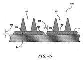
- Embodiments of vortex generator accessories 102 are depicted in Figs. 3 and 4 .
- Each accessory 102 includes a base portion 104 and a protrusion member 108 extending upwardly from the base portion 104.
- the protrusion member 108 may be any suitable flow disrupting configuration, such as a fin, or like structure.
- the invention in its broadest aspects is not limited to any particular shape or configuration of vortex generator or flow disruption protrusion member 108.
- the base portion 104 may be defined as a generally continuous plate-like structure that presents a generally flat, planar surface that contours and adheres to the mating blade surface.
- Functional components such as the protrusion member 108, may be formed integral with the base portion 104, or separately attached to the base portion 104.
- an attachment layer 110 connects the base portion 104 of the vortex generator accessory 102 to the respective suction or pressure side.
- the attachment layer 110 may, in certain embodiments, have a lower shear modulus than the base portion 104 to allow for shear slippage between the relatively stiff base portion 104 and the underlying rotor blade surface 24.
- the shear modulus is, in certain embodiments, within the range of 50Kpa - IMPa.
- the attachment layer 110 may be a double-sided adhesive sheet or strip material 112, such as a Very High Bond (VHB)/SAFT (Solar Acrylic Foam Tape) foam-based tape.
- VHB/SAFT foam-based materials are commercially available, for example from 3M Corporation of St. Paul, Minnesota, USA.
- the foam attachment layer 112 will sheer a small but defined amount with flexing of the underlying blade surfaces, thus reducing sheer stresses in the vortex generator accessory 102.
- the attachment layer 110 may be selected to have a particular thickness 116 ( Fig. 6 ) that provides the desired sheer slippage or strain isolation characteristic without adding a detrimental height aspect that could adversely affect the aerodynamic performance of the blade.
- the adhesive tape may have a thickness between 0.5 mm and 5.0 mm.
- the attachment layer 110 may be applied as a continuous strip between the base portion 104 and underlying blade surface 24, or may be applied in a discontinuous pattern.
- the attachment layer 110 may include a plurality of distinct strips 112 (e.g., tape or sheet strips) with a chord-wise gap between adjacent strips.
- the attachment layer may include span-wise gaps between distinct strips 112.
- the length of the vortex generator accessory 102 in combination with the attachment layer 11 is a factor that can be varied to reduce sheer stresses in the accessory 102.
- the vortex generator accessory 102 may de-bond from the blade surface.
- the base portion 104 it may be advantageous for the base portion 104 to have a span-wise length of between 0.1 meters to less than 2.0 meters, preferably less than 1.0 meters.
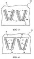
- Fig. 7 depicts an embodiment wherein the attachment layer 110 includes a layer of resin or putty 114 between the strip/sheet material layer 112 (such as a foam-based layer as described above) and the underlying blade surface.
- the overall thickness 116 of the attachment layer 110 is preferably within the limits discussed above in this embodiment.
- FIG. 6 and 7 embodiments are disclosed wherein multiple vortex generator accessories 102 are aligned and attached to the suction side surface 24 with a gap 118 between adjacent base portions 104.
- Each of the components base portions 104 may have a length of between 0.1 meters to less than 2.0 meters.
- Each of the base portions 104 has a respective attachment layer 110 that does not span the gap 118.
- Fillet seals 120 may be provided at the edges of the respective base portions 104 to protect the attachment layer 110 from moisture or other elements.
- the seals 120 may be, for example, any type of flexible caulking material.
- the vortex generator accessories include one or more flow disruption protrusion members 108 extending upwardly from the base portion 104.
- a single protrusion member 108 extends from each respective base portion 104.
- a plurality of the protrusion members 108 extend from a common base portion 104.
- the protrusion members 108 may be configured on the common base portion 104 in any desired pattern, such as the V-shaped formation depicted in Fig. 4 .
- Fig. 5 depicts another embodiment wherein multiple protrusion members 108 are configured on a common base portion.
- pairs of the protrusions 108 are arranged to form multiple V-shaped formations on a common base portion 104.
- multiple, separate vortex generator accessories 102 having a single fin-like protrusion member 108 are arranged on the blade surface 24 to define an overall vortex generator configuration along the span-wise aspect of the blade, as depicted in Fig. 2 .
- pairs of the vortex generator accessories 102 may be configured in V-shaped formations along the suction or pressure side of the blade.
- the present invention also encompasses various method embodiments for installing vortex generator accessories 102 to a suction 24 or pressure side 22 of a wind turbine rotor blade 16, wherein the vortex generator accessories 102 each have a base portion 104 and at least one protrusion member 108 extending upwardly from the base portion 104, as described above.
- a particular method embodiment includes defining a template 122 that is intended to be attached or placed on the suction or pressure side of the blade on which the vortex generator accessories 102 are to be attached.
- the template 122 is provided with location positions 124 defined thereon for placement of vortex generator accessories 102.
- the template may have a series of holes defined therethrough in a predefined pattern and orientation corresponding to a desired placement and orientation of the vortex generator accessories 102 on the blade surface 24.
- the location positions 24 are designed to provide a leading edge mark and a trailing edge mark for placement of the base portion on the suction or pressure side, wherein the leading edge and trailing edge of the base portion 104 is aligned with the leading and trailing edge marks made on the blade surface through the template. These marks may also give a desired angular orientation of the base portion on the blade surface.
- the template 122 may be variously configured.
- the template 122 is defined on a sheet member that contours to the wind turbine rotor blade 16. This sheet may be stored in roll form and subsequently unrolled for placement on the wind turbine blade 16 via suitable means, such as tape 126 illustrated in Fig. 8 .
- suitable means such as tape 126 illustrated in Fig. 8 .
- a releasable adhesive or mechanical attachment means may also be utilized. It may be desired to wrap the template 122 around either of the leading edge 26 or trailing edge 28, or to attach the template 122 without wrapping around either edges 26, 28, as depicted in Fig. 8 .
- the template 122 may have a more rigid configuration that is pre-shaped to the contours of the wind turbine blade 16.
- the template 122 may be a pre-formed shell member that fits onto the blade 16, for example with edge configurations that snap or otherwise fit over the leading and/or trailing edges 26, 28 of the blade 16.
- the template 122 is aligned and attached to the rotor blade surface 24 such that the location positions 124 are oriented span-wise along the desired suction or pressure side. Desirably a mark on the template 122 is aligned with structure on the blade 16 to ensure proper location and orientation of the template 122. For example, marks on the template 122 may align with marks on the blade surface 24 corresponding to the known pitch axis 40. As mentioned, the template 122 may be taped or otherwise removably attached to any of the blade surfaces for this purpose.
- the location positions 124 are then marked through the template 122 onto the suction side 24 by any suitable marking means, such as a marker, paint, mechanical device, and so forth.
- the template 122 is then removed from the wind turbine rotor blade 16 and the vortex generator accessories 102 are attached to the location positions 124 marked on the suction 24 or pressure side 22 of the blade in the manner described above.
- the method embodiments of the present invention are advantageous in that the vortex generator accessories 102 may be attached to existing wind turbine blades in the field without detaching the rotor blades from the hub.
Landscapes
- Engineering & Computer Science (AREA)
- Life Sciences & Earth Sciences (AREA)
- Sustainable Development (AREA)
- Sustainable Energy (AREA)
- Chemical & Material Sciences (AREA)
- Combustion & Propulsion (AREA)
- Mechanical Engineering (AREA)
- General Engineering & Computer Science (AREA)
- Physics & Mathematics (AREA)
- Fluid Mechanics (AREA)
- Wind Motors (AREA)
Claims (8)
- Procédé d'installation d'accessoires générateurs de tourbillons (102) à un côté d'aspiration (24) ou de refoulement (22) d'une pale de rotor d'éolienne (16), dans lequel les accessoire générateurs de tourbillons (102) ont chacun une partie de base (104) et au moins un élément saillant (108) s'étendant vers le haut depuis la partie de base (104), le procédé comprenant les étapes consistant à :définir un gabarit (122) avec des positions d'emplacement (124) qui y sont définies pour la mise en place d'accessoires générateurs de tourbillons (102) ;fixer le gabarit (122) à la pale de rotor (16) de l'éolienne de sorte que les positions d'emplacement (124) soient orientées dans le sens de l'envergure le long du côté d'aspiration (24) ou de refoulement (22) ;marquer les positions d'emplacement à travers le gabarit (122) sur le côté d'aspiration (24) ou de refoulement (22), dans lequel les positions d'emplacement (124) définissent un repère de bord d'attaque et un repère de bord de fuite séparé effectués via le gabarit pour la mise en place de la partie de base (104) sur le côté d'aspiration ou de refoulement ;retirer complètement le gabarit (122) de la pale de rotor d'éolienne (16) ; etcaractérisé en ce que :l'on attache les accessoires générateurs de tourbillons (102) aux positions d'emplacement repérées sur le côté d'aspiration (24) ou de refoulement (22) de la pale de rotor d'éolienne (16) en alignant un bord d'attaque et un bord de fuite du générateur de tourbillons aux repères de bord d'attaque et de bord de fuite séparés réalisés sur le côté d'aspiration ou le côté de refoulement.
- Procédé selon la revendication 1, dans lequel les accessoires générateurs de tourbillons (102) sont fixés au côté d'aspiration (24) ou de refoulement (22) avec l'utilisation d'une couche de fixation (110) raccordant la partie de base (104) au côté d'aspiration (24) ou de refoulement (22), la couche de fixation (110) ayant un module de cisaillement plus bas que la partie de base (104) pour permettre un coulissement de cisaillement entre la partie de base (104) et la section sous-jacente ou le côté de pression (24, 22).
- Procédé selon la revendication 1 ou 2, dans lequel la couche de fixation (110) comprend un élément en bande à base de mousse avec un adhésif appliqué sur ses côtés d'interface opposés.
- Procédé selon la revendication 3, dans lequel la couche de fixation (110) comprend un matériau en bande à base de mousse de type Very High Bond (VHB) ou SAFT (Solar Acrylic Foam Tape).
- Procédé selon l'une quelconque des revendications précédentes, dans lequel le gabarit (122) est défini sur un élément en feuille qui prend le contour de la pale de rotor (16) de l'éolienne.
- Procédé selon l'une quelconque des revendications précédentes, dans lequel les accessoires générateurs de tourbillons comprennent une pluralité des éléments saillants s'étendant de la partie de base.
- Procédé selon la revendication 6, dans lequel les éléments saillants sont aménagés dans une structure en forme de V sur la partie de base.
- Procédé selon l'une quelconque des revendications précédentes, dans lequel des paires des accessoires générateurs de tourbillons, sont montés dans le sens de l'envergure le long de la pale de manière à définir des structures en V le long du côté d'aspiration ou de refoulement.
Applications Claiming Priority (1)
| Application Number | Priority Date | Filing Date | Title |
|---|---|---|---|
| US13/875,627 US9556849B2 (en) | 2013-05-02 | 2013-05-02 | Attachment system and method for wind turbine vortex generators |
Publications (2)
| Publication Number | Publication Date |
|---|---|
| EP2799709A1 EP2799709A1 (fr) | 2014-11-05 |
| EP2799709B1 true EP2799709B1 (fr) | 2016-09-07 |
Family
ID=50513167
Family Applications (1)
| Application Number | Title | Priority Date | Filing Date |
|---|---|---|---|
| EP14165651.2A Active EP2799709B1 (fr) | 2013-05-02 | 2014-04-23 | Procédé de fixation des générateurs de tourbillons pour éolienne |
Country Status (3)
| Country | Link |
|---|---|
| US (1) | US9556849B2 (fr) |
| EP (1) | EP2799709B1 (fr) |
| DK (1) | DK2799709T3 (fr) |
Cited By (2)
| Publication number | Priority date | Publication date | Assignee | Title |
|---|---|---|---|---|
| EP3690230A1 (fr) | 2019-01-30 | 2020-08-05 | Nordex Energy GmbH | Générateur de vortex doté de panne simple |
| US11174834B2 (en) | 2018-03-13 | 2021-11-16 | Nordex Energy Se & Co. Kg | Vortex generator for fastening to a wind turbine rotor blade |
Families Citing this family (49)
| Publication number | Priority date | Publication date | Assignee | Title |
|---|---|---|---|---|
| EP2548800A1 (fr) * | 2011-07-22 | 2013-01-23 | LM Wind Power A/S | Procédés pour rééquiper des générateurs de vortex sur une pale d'éolienne |
| US9458821B2 (en) * | 2012-09-11 | 2016-10-04 | General Electric Company | Attachment system for a wind turbine rotor blade accessory |
| CN105556114B (zh) * | 2013-09-02 | 2020-06-05 | 沃本实业有限责任公司 | 用于风力涡轮机的涡流发生器 |
| DK178138B1 (en) * | 2014-07-16 | 2015-06-22 | Envision Energy | Vortex generator unit for a wind turbine blade |
| PL3177827T3 (pl) | 2014-08-05 | 2019-08-30 | Lm Wp Patent Holding A/S | Łopata turbiny wiatrowej z urządzeniem montowanym na powierzchni |
| US10180125B2 (en) * | 2015-04-20 | 2019-01-15 | General Electric Company | Airflow configuration for a wind turbine rotor blade |
| US9869295B2 (en) | 2015-05-07 | 2018-01-16 | General Electric Company | Attachment method to install components, such as tip extensions and winglets, to a wind turbine blade, as well as the wind turbine blade and component |
| US9869297B2 (en) | 2015-05-07 | 2018-01-16 | General Electric Company | Attachment method and system to install components, such as vortex generators, to a wind turbine blade |
| US9869296B2 (en) | 2015-05-07 | 2018-01-16 | General Electric Company | Attachment method and system to install components, such as tip extensions and winglets, to a wind turbine blade |
| EP3147569A1 (fr) * | 2015-09-28 | 2017-03-29 | General Electric Technology GmbH | Générateur de vortex et système d'injection de carburant d'une turbine à gaz avec un tel générateur |
| CN105240223A (zh) * | 2015-11-04 | 2016-01-13 | 苏州墨华高科信息技术有限公司 | 一种风电增幅器应用系统 |
| JP6148312B2 (ja) | 2015-11-12 | 2017-06-14 | 三菱重工業株式会社 | ボルテックスジェネレータ、風車翼および風力発電装置 |
| US11015569B2 (en) | 2015-11-12 | 2021-05-25 | Mitsubishi Heavy Industries, Ltd. | Vortex generator, wind turbine blade, and wind turbine power generating apparatus |
| JP6153989B2 (ja) | 2015-11-13 | 2017-06-28 | 三菱重工業株式会社 | ボルテックスジェネレータ、風車翼および風力発電装置 |
| GB201520725D0 (en) | 2015-11-24 | 2016-01-06 | Vestas Wind Sys As | improvements relating to wind turbine blades |
| JP6148364B1 (ja) | 2016-02-26 | 2017-06-14 | 三菱重工業株式会社 | 風車翼用ボルテックスジェネレータ、風車翼、風力発電装置、及びボルテックスジェネレータの取付方法 |
| JP6154037B1 (ja) * | 2016-02-26 | 2017-06-28 | 三菱重工業株式会社 | ボルテックスジェネレータの取付方法及びテンプレート |
| USD809460S1 (en) | 2016-03-16 | 2018-02-06 | Mitsubishi Heavy Industries, Ltd. | Vortex generator for wind turbines |
| CN105822511B (zh) * | 2016-05-16 | 2018-06-19 | 宜春学院 | 一种安装涡流发生器或类似流动控制装置的方法和装置 |
| CN106050551B (zh) * | 2016-05-25 | 2019-01-15 | 新疆金风科技股份有限公司 | 涡流发生装置及风力发电机组的叶片 |
| US20180038342A1 (en) * | 2016-08-05 | 2018-02-08 | General Electric Company | Vortex generators for wind turbine rotor blades |
| US10487798B2 (en) * | 2016-08-05 | 2019-11-26 | General Electric Company | System and method for locating airflow modifiers for installation on a wind turbine rotor blade |
| JP6154050B1 (ja) | 2016-08-08 | 2017-06-28 | 三菱重工業株式会社 | 風車翼、風車ロータ及び風力発電装置並びにボルテックスジェネレータの取付方法 |
| PL3869029T3 (pl) * | 2016-09-07 | 2024-03-25 | Lm Wind Power A/S | Mocowanie urządzenia generującego zawirowania na łopacie turbiny wiatrowej |
| US10487796B2 (en) | 2016-10-13 | 2019-11-26 | General Electric Company | Attachment methods for surface features of wind turbine rotor blades |
| JP6632553B2 (ja) | 2017-01-16 | 2020-01-22 | 三菱重工業株式会社 | ボルテックスジェネレータ及びその設置方法、並びに風車翼及び風力発電装置 |
| JP6840172B2 (ja) * | 2017-01-24 | 2021-03-10 | 株式会社日立製作所 | 流体機器 |
| US11536245B2 (en) | 2017-01-26 | 2022-12-27 | General Electric Company | Rotor blade assembly and a wind turbine having the rotor blade assembly |
| US10830206B2 (en) | 2017-02-03 | 2020-11-10 | General Electric Company | Methods for manufacturing wind turbine rotor blades and components thereof |
| US11098691B2 (en) | 2017-02-03 | 2021-08-24 | General Electric Company | Methods for manufacturing wind turbine rotor blades and components thereof |
| US20190024631A1 (en) * | 2017-07-20 | 2019-01-24 | General Electric Company | Airflow configuration for a wind turbine rotor blade |
| US10920745B2 (en) | 2017-11-21 | 2021-02-16 | General Electric Company | Wind turbine rotor blade components and methods of manufacturing the same |
| US11668275B2 (en) | 2017-11-21 | 2023-06-06 | General Electric Company | Methods for manufacturing an outer skin of a rotor blade |
| US11390013B2 (en) | 2017-11-21 | 2022-07-19 | General Electric Company | Vacuum forming mold assembly and associated methods |
| US10913216B2 (en) | 2017-11-21 | 2021-02-09 | General Electric Company | Methods for manufacturing wind turbine rotor blade panels having printed grid structures |
| US11248582B2 (en) | 2017-11-21 | 2022-02-15 | General Electric Company | Multiple material combinations for printed reinforcement structures of rotor blades |
| US10773464B2 (en) | 2017-11-21 | 2020-09-15 | General Electric Company | Method for manufacturing composite airfoils |
| US10865769B2 (en) | 2017-11-21 | 2020-12-15 | General Electric Company | Methods for manufacturing wind turbine rotor blade panels having printed grid structures |
| US11040503B2 (en) | 2017-11-21 | 2021-06-22 | General Electric Company | Apparatus for manufacturing composite airfoils |
| US10821652B2 (en) | 2017-11-21 | 2020-11-03 | General Electric Company | Vacuum forming mold assembly and method for creating a vacuum forming mold assembly |
| US11035339B2 (en) | 2018-03-26 | 2021-06-15 | General Electric Company | Shear web assembly interconnected with additive manufactured components |
| US10821696B2 (en) | 2018-03-26 | 2020-11-03 | General Electric Company | Methods for manufacturing flatback airfoils for wind turbine rotor blades |
| EP3567243A1 (fr) * | 2018-05-11 | 2019-11-13 | General Electric Company | Protection de bord d'attaque de pale de turbine éolienne |
| DE102018117398A1 (de) * | 2018-07-18 | 2020-01-23 | Wobben Properties Gmbh | Rotorblatt für eine Windenergieanlage und Windenergieanlage |
| GB202011064D0 (en) * | 2020-07-17 | 2020-09-02 | Lm Wind Power As | Vortex generator tape for a wind turbine blade |
| EP3978748A1 (fr) * | 2020-10-01 | 2022-04-06 | Siemens Gamesa Renewable Energy A/S | Composant d'éolienne, éolienne et procédé de fabrication d'un composant d'éolienne |
| JP7063973B1 (ja) * | 2020-11-27 | 2022-05-09 | 三菱重工業株式会社 | 風車翼用のボルテックスジェネレータ、風車翼及び風力発電装置並びに風車翼の製造方法 |
| KR102596143B1 (ko) * | 2021-12-03 | 2023-11-01 | 삼성중공업 주식회사 | 풍력 발전기용 블레이드 |
| KR102562255B1 (ko) * | 2021-12-03 | 2023-08-02 | 삼성중공업 주식회사 | 풍력 발전기용 블레이드 |
Family Cites Families (36)
| Publication number | Priority date | Publication date | Assignee | Title |
|---|---|---|---|---|
| USRE19412E (en) | 1935-01-01 | Aircraft and control thereof | ||
| US2450440A (en) | 1944-12-19 | 1948-10-05 | Roscoe H Mills | Propeller blade construction |
| US3528753A (en) | 1968-06-14 | 1970-09-15 | United Aircraft Corp | Helicopter blade with non-homogeneous structural spar |
| US3586460A (en) | 1969-05-14 | 1971-06-22 | Us Air Force | Rotor blade variable modulus trailing edge |
| US4136460A (en) * | 1977-03-21 | 1979-01-30 | Cornwall Della E | Adjustable buttonhole sewing guide |
| US4329119A (en) | 1977-08-02 | 1982-05-11 | The Boeing Company | Rotor blade internal damper |
| US4360871A (en) * | 1978-12-22 | 1982-11-23 | United Technologies Corporation | Method for fabricating wind turbine blades |
| FR2542695B1 (fr) | 1983-03-18 | 1985-07-26 | Aerospatiale | Helice multipale a pas variable a pale s en materiaux composites demontables individuellement, procede de fabrication de telles pales et pales ainsi realisees |
| US5346367A (en) | 1984-12-21 | 1994-09-13 | United Technologies Corporation | Advanced composite rotor blade |
| US5088665A (en) | 1989-10-31 | 1992-02-18 | The United States Of America As Represented By The Administrator Of The National Aeronautics And Space Administration | Serrated trailing edges for improving lift and drag characteristics of lifting surfaces |
| US7059833B2 (en) | 2001-11-26 | 2006-06-13 | Bonus Energy A/S | Method for improvement of the efficiency of a wind turbine rotor |
| ES2627790T3 (es) * | 2005-05-17 | 2017-07-31 | Vestas Wind Systems A/S | Pala de turbina eólica controlada por cabeceo que tiene medios de generación de turbulencia, turbina eólica y uso de la misma |
| US7637721B2 (en) | 2005-07-29 | 2009-12-29 | General Electric Company | Methods and apparatus for producing wind energy with reduced wind turbine noise |
| US7458777B2 (en) | 2005-09-22 | 2008-12-02 | General Electric Company | Wind turbine rotor assembly and blade having acoustic flap |
| ES2318925B1 (es) | 2005-09-22 | 2010-02-11 | GAMESA INNOVATION & TECHNOLOGY, S.L. | Aerogenerador con un rotor de palas que reduce el ruido. |
| ATE537356T1 (de) | 2006-06-09 | 2011-12-15 | Vestas Wind Sys As | Windturbinenrotorblatt und pitchgeregelte windturbine |
| US20090074585A1 (en) | 2007-09-19 | 2009-03-19 | General Electric Company | Wind turbine blades with trailing edge serrations |
| US20090084932A1 (en) * | 2007-09-27 | 2009-04-02 | General Electric Company | Wind turbine blade molds |
| WO2009080038A1 (fr) * | 2007-12-21 | 2009-07-02 | Vestas Wind Systems A/S | Procédé de réparation d'un élément solide composite à fibres |
| US8075278B2 (en) | 2009-05-21 | 2011-12-13 | Zuteck Michael D | Shell structure of wind turbine blade having regions of low shear modulus |
| US8079819B2 (en) | 2009-05-21 | 2011-12-20 | Zuteck Michael D | Optimization of premium fiber material usage in wind turbine spars |
| US20110100540A1 (en) * | 2009-10-30 | 2011-05-05 | General Electric Company | Methods of manufacture of wind turbine blades and other structures |
| US8061986B2 (en) | 2010-06-11 | 2011-11-22 | General Electric Company | Wind turbine blades with controllable aerodynamic vortex elements |
| US8083488B2 (en) | 2010-08-23 | 2011-12-27 | General Electric Company | Blade extension for rotor blade in wind turbine |
| US8038407B2 (en) | 2010-09-14 | 2011-10-18 | General Electric Company | Wind turbine blade with improved trailing edge bond |
| EP2444658B1 (fr) | 2010-10-21 | 2016-10-19 | Siemens Aktiengesellschaft | Procédé de rééquipement pour une pale d'éolienne |
| US7976276B2 (en) | 2010-11-04 | 2011-07-12 | General Electric Company | Noise reducer for rotor blade in wind turbine |
| CA2824611A1 (fr) | 2010-12-16 | 2012-06-21 | Inventus Holdings, Llc | Procede de determination du positionnement optimal d'un generateur de vortex pour un rendement maximal sur un aerogenerateur reconditionne de dessin aerodynamique inconnu |
| US20110268558A1 (en) | 2010-12-20 | 2011-11-03 | General Electric Company | Noise reducer for rotor blade in wind turbine |
| EP2484896B1 (fr) * | 2011-02-04 | 2014-04-23 | LM WP Patent Holding A/S | Montage de dispositifs générateurs de vortex sur la pale d'une éolienne au moyen d'une plaque de montage |
| EP2484895A1 (fr) | 2011-02-04 | 2012-08-08 | LM Wind Power A/S | Paire d'aubes de générateur de tourbillons doté d'une base en forme de trapèze |
| US8414261B2 (en) | 2011-05-31 | 2013-04-09 | General Electric Company | Noise reducer for rotor blade in wind turbine |
| EP2532510B1 (fr) | 2011-06-07 | 2016-11-16 | Siemens Aktiengesellschaft | Procédé de modification de la forme de surface d'une pale de rotor d'éolienne |
| US20130045105A1 (en) | 2011-08-17 | 2013-02-21 | Howard Daniel Driver | Wind turbine blade and method of protecting the same |
| US8834127B2 (en) | 2011-09-09 | 2014-09-16 | General Electric Company | Extension for rotor blade in wind turbine |
| DE102012000431A1 (de) | 2012-01-12 | 2013-07-18 | Smart Blade Gmbh | Rotorblatt |
-
2013
- 2013-05-02 US US13/875,627 patent/US9556849B2/en active Active
-
2014
- 2014-04-23 EP EP14165651.2A patent/EP2799709B1/fr active Active
- 2014-04-23 DK DK14165651.2T patent/DK2799709T3/en active
Cited By (2)
| Publication number | Priority date | Publication date | Assignee | Title |
|---|---|---|---|---|
| US11174834B2 (en) | 2018-03-13 | 2021-11-16 | Nordex Energy Se & Co. Kg | Vortex generator for fastening to a wind turbine rotor blade |
| EP3690230A1 (fr) | 2019-01-30 | 2020-08-05 | Nordex Energy GmbH | Générateur de vortex doté de panne simple |
Also Published As
| Publication number | Publication date |
|---|---|
| DK2799709T3 (en) | 2016-10-24 |
| US9556849B2 (en) | 2017-01-31 |
| EP2799709A1 (fr) | 2014-11-05 |
| US20140328692A1 (en) | 2014-11-06 |
Similar Documents
| Publication | Publication Date | Title |
|---|---|---|
| EP2799709B1 (fr) | Procédé de fixation des générateurs de tourbillons pour éolienne | |
| EP2706228B1 (fr) | Ensemble formant pale de rotor pour éolienne | |
| US10443579B2 (en) | Tip extensions for wind turbine rotor blades and methods of installing same | |
| EP3091225B1 (fr) | Pale d'éolienne et procédé de fixation pour installer des éléments, tels que des extensions de pointe et d'ailettes, à une pale d'éolienne | |
| US9869297B2 (en) | Attachment method and system to install components, such as vortex generators, to a wind turbine blade | |
| EP3091224B1 (fr) | Pale d'éolienne et procédé de fixation d'éléments, tels que des ailettes et prolongement d'extrémité, à une pale d'éolienne | |
| EP2801720B1 (fr) | Ensemble de modification de flux d'air pour une pale de rotor d'une éolienne | |
| US10584676B2 (en) | Wind turbine rotor blade assembly with surface features | |
| EP2799710B1 (fr) | Ensemble de pale de rotor comportant des générateurs de tourbillons pour éolienne | |
| CA2918917C (fr) | Generateur de tourbillon pour pale de rotor | |
| EP3279467B1 (fr) | Générateurs de vortex pour pales de rotor d'éolienne | |
| CA3097518A1 (fr) | Extensions de pointe pour pales de rotor d'eolienne et leurs procedes d'installation |
Legal Events
| Date | Code | Title | Description |
|---|---|---|---|
| PUAI | Public reference made under article 153(3) epc to a published international application that has entered the european phase |
Free format text: ORIGINAL CODE: 0009012 |
|
| 17P | Request for examination filed |
Effective date: 20140423 |
|
| AK | Designated contracting states |
Kind code of ref document: A1 Designated state(s): AL AT BE BG CH CY CZ DE DK EE ES FI FR GB GR HR HU IE IS IT LI LT LU LV MC MK MT NL NO PL PT RO RS SE SI SK SM TR |
|
| AX | Request for extension of the european patent |
Extension state: BA ME |
|
| R17P | Request for examination filed (corrected) |
Effective date: 20150506 |
|
| RBV | Designated contracting states (corrected) |
Designated state(s): AL AT BE BG CH CY CZ DE DK EE ES FI FR GB GR HR HU IE IS IT LI LT LU LV MC MK MT NL NO PL PT RO RS SE SI SK SM TR |
|
| 17Q | First examination report despatched |
Effective date: 20150922 |
|
| GRAP | Despatch of communication of intention to grant a patent |
Free format text: ORIGINAL CODE: EPIDOSNIGR1 |
|
| INTG | Intention to grant announced |
Effective date: 20160531 |
|
| GRAS | Grant fee paid |
Free format text: ORIGINAL CODE: EPIDOSNIGR3 |
|
| GRAA | (expected) grant |
Free format text: ORIGINAL CODE: 0009210 |
|
| AK | Designated contracting states |
Kind code of ref document: B1 Designated state(s): AL AT BE BG CH CY CZ DE DK EE ES FI FR GB GR HR HU IE IS IT LI LT LU LV MC MK MT NL NO PL PT RO RS SE SI SK SM TR |
|
| REG | Reference to a national code |
Ref country code: GB Ref legal event code: FG4D |
|
| REG | Reference to a national code |
Ref country code: CH Ref legal event code: EP |
|
| REG | Reference to a national code |
Ref country code: IE Ref legal event code: FG4D |
|
| REG | Reference to a national code |
Ref country code: AT Ref legal event code: REF Ref document number: 827122 Country of ref document: AT Kind code of ref document: T Effective date: 20161015 |
|
| REG | Reference to a national code |
Ref country code: DE Ref legal event code: R096 Ref document number: 602014003459 Country of ref document: DE |
|
| REG | Reference to a national code |
Ref country code: DK Ref legal event code: T3 Effective date: 20161021 |
|
| REG | Reference to a national code |
Ref country code: LT Ref legal event code: MG4D |
|
| REG | Reference to a national code |
Ref country code: NL Ref legal event code: MP Effective date: 20160907 |
|
| PG25 | Lapsed in a contracting state [announced via postgrant information from national office to epo] |
Ref country code: NO Free format text: LAPSE BECAUSE OF FAILURE TO SUBMIT A TRANSLATION OF THE DESCRIPTION OR TO PAY THE FEE WITHIN THE PRESCRIBED TIME-LIMIT Effective date: 20161207 Ref country code: FI Free format text: LAPSE BECAUSE OF FAILURE TO SUBMIT A TRANSLATION OF THE DESCRIPTION OR TO PAY THE FEE WITHIN THE PRESCRIBED TIME-LIMIT Effective date: 20160907 Ref country code: HR Free format text: LAPSE BECAUSE OF FAILURE TO SUBMIT A TRANSLATION OF THE DESCRIPTION OR TO PAY THE FEE WITHIN THE PRESCRIBED TIME-LIMIT Effective date: 20160907 Ref country code: RS Free format text: LAPSE BECAUSE OF FAILURE TO SUBMIT A TRANSLATION OF THE DESCRIPTION OR TO PAY THE FEE WITHIN THE PRESCRIBED TIME-LIMIT Effective date: 20160907 Ref country code: LT Free format text: LAPSE BECAUSE OF FAILURE TO SUBMIT A TRANSLATION OF THE DESCRIPTION OR TO PAY THE FEE WITHIN THE PRESCRIBED TIME-LIMIT Effective date: 20160907 |
|
| REG | Reference to a national code |
Ref country code: AT Ref legal event code: MK05 Ref document number: 827122 Country of ref document: AT Kind code of ref document: T Effective date: 20160907 |
|
| PG25 | Lapsed in a contracting state [announced via postgrant information from national office to epo] |
Ref country code: SE Free format text: LAPSE BECAUSE OF FAILURE TO SUBMIT A TRANSLATION OF THE DESCRIPTION OR TO PAY THE FEE WITHIN THE PRESCRIBED TIME-LIMIT Effective date: 20160907 Ref country code: NL Free format text: LAPSE BECAUSE OF FAILURE TO SUBMIT A TRANSLATION OF THE DESCRIPTION OR TO PAY THE FEE WITHIN THE PRESCRIBED TIME-LIMIT Effective date: 20160907 Ref country code: ES Free format text: LAPSE BECAUSE OF FAILURE TO SUBMIT A TRANSLATION OF THE DESCRIPTION OR TO PAY THE FEE WITHIN THE PRESCRIBED TIME-LIMIT Effective date: 20160907 Ref country code: GR Free format text: LAPSE BECAUSE OF FAILURE TO SUBMIT A TRANSLATION OF THE DESCRIPTION OR TO PAY THE FEE WITHIN THE PRESCRIBED TIME-LIMIT Effective date: 20161208 Ref country code: LV Free format text: LAPSE BECAUSE OF FAILURE TO SUBMIT A TRANSLATION OF THE DESCRIPTION OR TO PAY THE FEE WITHIN THE PRESCRIBED TIME-LIMIT Effective date: 20160907 |
|
| PG25 | Lapsed in a contracting state [announced via postgrant information from national office to epo] |
Ref country code: EE Free format text: LAPSE BECAUSE OF FAILURE TO SUBMIT A TRANSLATION OF THE DESCRIPTION OR TO PAY THE FEE WITHIN THE PRESCRIBED TIME-LIMIT Effective date: 20160907 Ref country code: RO Free format text: LAPSE BECAUSE OF FAILURE TO SUBMIT A TRANSLATION OF THE DESCRIPTION OR TO PAY THE FEE WITHIN THE PRESCRIBED TIME-LIMIT Effective date: 20160907 |
|
| PG25 | Lapsed in a contracting state [announced via postgrant information from national office to epo] |
Ref country code: CZ Free format text: LAPSE BECAUSE OF FAILURE TO SUBMIT A TRANSLATION OF THE DESCRIPTION OR TO PAY THE FEE WITHIN THE PRESCRIBED TIME-LIMIT Effective date: 20160907 Ref country code: SK Free format text: LAPSE BECAUSE OF FAILURE TO SUBMIT A TRANSLATION OF THE DESCRIPTION OR TO PAY THE FEE WITHIN THE PRESCRIBED TIME-LIMIT Effective date: 20160907 Ref country code: PL Free format text: LAPSE BECAUSE OF FAILURE TO SUBMIT A TRANSLATION OF THE DESCRIPTION OR TO PAY THE FEE WITHIN THE PRESCRIBED TIME-LIMIT Effective date: 20160907 Ref country code: BE Free format text: LAPSE BECAUSE OF FAILURE TO SUBMIT A TRANSLATION OF THE DESCRIPTION OR TO PAY THE FEE WITHIN THE PRESCRIBED TIME-LIMIT Effective date: 20160907 Ref country code: AT Free format text: LAPSE BECAUSE OF FAILURE TO SUBMIT A TRANSLATION OF THE DESCRIPTION OR TO PAY THE FEE WITHIN THE PRESCRIBED TIME-LIMIT Effective date: 20160907 Ref country code: BG Free format text: LAPSE BECAUSE OF FAILURE TO SUBMIT A TRANSLATION OF THE DESCRIPTION OR TO PAY THE FEE WITHIN THE PRESCRIBED TIME-LIMIT Effective date: 20161207 Ref country code: IS Free format text: LAPSE BECAUSE OF FAILURE TO SUBMIT A TRANSLATION OF THE DESCRIPTION OR TO PAY THE FEE WITHIN THE PRESCRIBED TIME-LIMIT Effective date: 20170107 Ref country code: SM Free format text: LAPSE BECAUSE OF FAILURE TO SUBMIT A TRANSLATION OF THE DESCRIPTION OR TO PAY THE FEE WITHIN THE PRESCRIBED TIME-LIMIT Effective date: 20160907 Ref country code: PT Free format text: LAPSE BECAUSE OF FAILURE TO SUBMIT A TRANSLATION OF THE DESCRIPTION OR TO PAY THE FEE WITHIN THE PRESCRIBED TIME-LIMIT Effective date: 20170109 |
|
| REG | Reference to a national code |
Ref country code: DE Ref legal event code: R097 Ref document number: 602014003459 Country of ref document: DE |
|
| PG25 | Lapsed in a contracting state [announced via postgrant information from national office to epo] |
Ref country code: IT Free format text: LAPSE BECAUSE OF FAILURE TO SUBMIT A TRANSLATION OF THE DESCRIPTION OR TO PAY THE FEE WITHIN THE PRESCRIBED TIME-LIMIT Effective date: 20160907 |
|
| PLBE | No opposition filed within time limit |
Free format text: ORIGINAL CODE: 0009261 |
|
| STAA | Information on the status of an ep patent application or granted ep patent |
Free format text: STATUS: NO OPPOSITION FILED WITHIN TIME LIMIT |
|
| 26N | No opposition filed |
Effective date: 20170608 |
|
| PG25 | Lapsed in a contracting state [announced via postgrant information from national office to epo] |
Ref country code: SI Free format text: LAPSE BECAUSE OF FAILURE TO SUBMIT A TRANSLATION OF THE DESCRIPTION OR TO PAY THE FEE WITHIN THE PRESCRIBED TIME-LIMIT Effective date: 20160907 |
|
| REG | Reference to a national code |
Ref country code: CH Ref legal event code: PL |
|
| REG | Reference to a national code |
Ref country code: IE Ref legal event code: MM4A |
|
| REG | Reference to a national code |
Ref country code: FR Ref legal event code: ST Effective date: 20171229 |
|
| PG25 | Lapsed in a contracting state [announced via postgrant information from national office to epo] |
Ref country code: FR Free format text: LAPSE BECAUSE OF NON-PAYMENT OF DUE FEES Effective date: 20170502 Ref country code: MC Free format text: LAPSE BECAUSE OF FAILURE TO SUBMIT A TRANSLATION OF THE DESCRIPTION OR TO PAY THE FEE WITHIN THE PRESCRIBED TIME-LIMIT Effective date: 20160907 |
|
| PG25 | Lapsed in a contracting state [announced via postgrant information from national office to epo] |
Ref country code: LI Free format text: LAPSE BECAUSE OF NON-PAYMENT OF DUE FEES Effective date: 20170430 Ref country code: LU Free format text: LAPSE BECAUSE OF NON-PAYMENT OF DUE FEES Effective date: 20170423 Ref country code: CH Free format text: LAPSE BECAUSE OF NON-PAYMENT OF DUE FEES Effective date: 20170430 |
|
| PG25 | Lapsed in a contracting state [announced via postgrant information from national office to epo] |
Ref country code: IE Free format text: LAPSE BECAUSE OF NON-PAYMENT OF DUE FEES Effective date: 20170423 |
|
| PG25 | Lapsed in a contracting state [announced via postgrant information from national office to epo] |
Ref country code: MT Free format text: LAPSE BECAUSE OF NON-PAYMENT OF DUE FEES Effective date: 20170423 |
|
| PG25 | Lapsed in a contracting state [announced via postgrant information from national office to epo] |
Ref country code: AL Free format text: LAPSE BECAUSE OF FAILURE TO SUBMIT A TRANSLATION OF THE DESCRIPTION OR TO PAY THE FEE WITHIN THE PRESCRIBED TIME-LIMIT Effective date: 20160907 |
|
| GBPC | Gb: european patent ceased through non-payment of renewal fee |
Effective date: 20180423 |
|
| PG25 | Lapsed in a contracting state [announced via postgrant information from national office to epo] |
Ref country code: GB Free format text: LAPSE BECAUSE OF NON-PAYMENT OF DUE FEES Effective date: 20180423 |
|
| PG25 | Lapsed in a contracting state [announced via postgrant information from national office to epo] |
Ref country code: HU Free format text: LAPSE BECAUSE OF FAILURE TO SUBMIT A TRANSLATION OF THE DESCRIPTION OR TO PAY THE FEE WITHIN THE PRESCRIBED TIME-LIMIT; INVALID AB INITIO Effective date: 20140423 |
|
| PG25 | Lapsed in a contracting state [announced via postgrant information from national office to epo] |
Ref country code: CY Free format text: LAPSE BECAUSE OF FAILURE TO SUBMIT A TRANSLATION OF THE DESCRIPTION OR TO PAY THE FEE WITHIN THE PRESCRIBED TIME-LIMIT Effective date: 20160907 |
|
| PG25 | Lapsed in a contracting state [announced via postgrant information from national office to epo] |
Ref country code: MK Free format text: LAPSE BECAUSE OF FAILURE TO SUBMIT A TRANSLATION OF THE DESCRIPTION OR TO PAY THE FEE WITHIN THE PRESCRIBED TIME-LIMIT Effective date: 20160907 |
|
| PGFP | Annual fee paid to national office [announced via postgrant information from national office to epo] |
Ref country code: DK Payment date: 20230321 Year of fee payment: 10 |
|
| PGFP | Annual fee paid to national office [announced via postgrant information from national office to epo] |
Ref country code: TR Payment date: 20230324 Year of fee payment: 10 |
|
| P01 | Opt-out of the competence of the unified patent court (upc) registered |
Effective date: 20230522 |
|
| PGFP | Annual fee paid to national office [announced via postgrant information from national office to epo] |
Ref country code: DE Payment date: 20230321 Year of fee payment: 10 |
|
| REG | Reference to a national code |
Ref country code: DE Ref legal event code: R081 Ref document number: 602014003459 Country of ref document: DE Owner name: GENERAL ELECTRIC RENOVABLES ESPANA, S.L., ES Free format text: FORMER OWNER: GENERAL ELECTRIC COMPANY, SCHENECTADY, NY, US |