EP2799579A1 - Grain-oriented electrical steel sheet and method for manufacturing the same - Google Patents
Grain-oriented electrical steel sheet and method for manufacturing the same Download PDFInfo
- Publication number
- EP2799579A1 EP2799579A1 EP12863996.0A EP12863996A EP2799579A1 EP 2799579 A1 EP2799579 A1 EP 2799579A1 EP 12863996 A EP12863996 A EP 12863996A EP 2799579 A1 EP2799579 A1 EP 2799579A1
- Authority
- EP
- European Patent Office
- Prior art keywords
- steel sheet
- grain
- oriented electrical
- irradiation
- electrical steel
- Prior art date
- Legal status (The legal status is an assumption and is not a legal conclusion. Google has not performed a legal analysis and makes no representation as to the accuracy of the status listed.)
- Granted
Links
- 229910001224 Grain-oriented electrical steel Inorganic materials 0.000 title claims abstract description 68
- 238000000034 method Methods 0.000 title claims description 38
- 238000004519 manufacturing process Methods 0.000 title claims description 25
- 229910000831 Steel Inorganic materials 0.000 claims abstract description 94
- 239000010959 steel Substances 0.000 claims abstract description 94
- 239000011248 coating agent Substances 0.000 claims abstract description 62
- 238000000576 coating method Methods 0.000 claims abstract description 62
- 238000005096 rolling process Methods 0.000 claims abstract description 28
- 239000000758 substrate Substances 0.000 claims abstract description 20
- 238000000137 annealing Methods 0.000 claims description 43
- 238000010894 electron beam technology Methods 0.000 claims description 24
- 230000001678 irradiating effect Effects 0.000 claims description 19
- 238000001953 recrystallisation Methods 0.000 claims description 14
- 238000005121 nitriding Methods 0.000 claims description 11
- 238000009413 insulation Methods 0.000 abstract description 34
- 230000005381 magnetic domain Effects 0.000 abstract description 33
- 238000007670 refining Methods 0.000 abstract description 11
- 230000007797 corrosion Effects 0.000 abstract description 8
- 238000005260 corrosion Methods 0.000 abstract description 8
- XEEYBQQBJWHFJM-UHFFFAOYSA-N Iron Chemical group [Fe] XEEYBQQBJWHFJM-UHFFFAOYSA-N 0.000 description 50
- 229910052742 iron Inorganic materials 0.000 description 23
- 230000000694 effects Effects 0.000 description 18
- 239000007788 liquid Substances 0.000 description 11
- 239000011572 manganese Substances 0.000 description 9
- 239000000463 material Substances 0.000 description 9
- 238000005259 measurement Methods 0.000 description 8
- PXHVJJICTQNCMI-UHFFFAOYSA-N nickel Substances [Ni] PXHVJJICTQNCMI-UHFFFAOYSA-N 0.000 description 8
- 229910052757 nitrogen Inorganic materials 0.000 description 7
- 229910052782 aluminium Inorganic materials 0.000 description 6
- 239000003112 inhibitor Substances 0.000 description 6
- 230000004907 flux Effects 0.000 description 5
- 230000001771 impaired effect Effects 0.000 description 5
- IJGRMHOSHXDMSA-UHFFFAOYSA-N Atomic nitrogen Chemical compound N#N IJGRMHOSHXDMSA-UHFFFAOYSA-N 0.000 description 4
- 230000001133 acceleration Effects 0.000 description 4
- 239000007864 aqueous solution Substances 0.000 description 4
- 239000010949 copper Substances 0.000 description 4
- 230000007423 decrease Effects 0.000 description 4
- 229910052839 forsterite Inorganic materials 0.000 description 4
- HCWCAKKEBCNQJP-UHFFFAOYSA-N magnesium orthosilicate Chemical compound [Mg+2].[Mg+2].[O-][Si]([O-])([O-])[O-] HCWCAKKEBCNQJP-UHFFFAOYSA-N 0.000 description 4
- 229910052748 manganese Inorganic materials 0.000 description 4
- 229910052711 selenium Inorganic materials 0.000 description 4
- 229910052717 sulfur Inorganic materials 0.000 description 4
- ILRRQNADMUWWFW-UHFFFAOYSA-K aluminium phosphate Chemical compound O1[Al]2OP1(=O)O2 ILRRQNADMUWWFW-UHFFFAOYSA-K 0.000 description 3
- 239000011651 chromium Substances 0.000 description 3
- 229910052802 copper Inorganic materials 0.000 description 3
- 238000005098 hot rolling Methods 0.000 description 3
- 239000012535 impurity Substances 0.000 description 3
- 239000000203 mixture Substances 0.000 description 3
- 230000003287 optical effect Effects 0.000 description 3
- 238000000746 purification Methods 0.000 description 3
- 239000000126 substance Substances 0.000 description 3
- 229910001208 Crucible steel Inorganic materials 0.000 description 2
- VYPSYNLAJGMNEJ-UHFFFAOYSA-N Silicium dioxide Chemical compound O=[Si]=O VYPSYNLAJGMNEJ-UHFFFAOYSA-N 0.000 description 2
- 229910052787 antimony Inorganic materials 0.000 description 2
- KGBXLFKZBHKPEV-UHFFFAOYSA-N boric acid Chemical compound OB(O)O KGBXLFKZBHKPEV-UHFFFAOYSA-N 0.000 description 2
- 239000004327 boric acid Substances 0.000 description 2
- 238000005266 casting Methods 0.000 description 2
- 229910052804 chromium Inorganic materials 0.000 description 2
- 239000008119 colloidal silica Substances 0.000 description 2
- 238000009749 continuous casting Methods 0.000 description 2
- 238000002474 experimental method Methods 0.000 description 2
- 239000000835 fiber Substances 0.000 description 2
- CRGGPIWCSGOBDN-UHFFFAOYSA-N magnesium;dioxido(dioxo)chromium Chemical compound [Mg+2].[O-][Cr]([O-])(=O)=O CRGGPIWCSGOBDN-UHFFFAOYSA-N 0.000 description 2
- 229910052750 molybdenum Inorganic materials 0.000 description 2
- 229910052759 nickel Inorganic materials 0.000 description 2
- 230000010355 oscillation Effects 0.000 description 2
- 229910052698 phosphorus Inorganic materials 0.000 description 2
- 229910052718 tin Inorganic materials 0.000 description 2
- VYZAMTAEIAYCRO-UHFFFAOYSA-N Chromium Chemical compound [Cr] VYZAMTAEIAYCRO-UHFFFAOYSA-N 0.000 description 1
- RYGMFSIKBFXOCR-UHFFFAOYSA-N Copper Chemical compound [Cu] RYGMFSIKBFXOCR-UHFFFAOYSA-N 0.000 description 1
- PWHULOQIROXLJO-UHFFFAOYSA-N Manganese Chemical compound [Mn] PWHULOQIROXLJO-UHFFFAOYSA-N 0.000 description 1
- ZOKXTWBITQBERF-UHFFFAOYSA-N Molybdenum Chemical compound [Mo] ZOKXTWBITQBERF-UHFFFAOYSA-N 0.000 description 1
- OAICVXFJPJFONN-UHFFFAOYSA-N Phosphorus Chemical compound [P] OAICVXFJPJFONN-UHFFFAOYSA-N 0.000 description 1
- XUIMIQQOPSSXEZ-UHFFFAOYSA-N Silicon Chemical compound [Si] XUIMIQQOPSSXEZ-UHFFFAOYSA-N 0.000 description 1
- ATJFFYVFTNAWJD-UHFFFAOYSA-N Tin Chemical compound [Sn] ATJFFYVFTNAWJD-UHFFFAOYSA-N 0.000 description 1
- 230000032683 aging Effects 0.000 description 1
- WATWJIUSRGPENY-UHFFFAOYSA-N antimony atom Chemical compound [Sb] WATWJIUSRGPENY-UHFFFAOYSA-N 0.000 description 1
- 238000013459 approach Methods 0.000 description 1
- 230000015572 biosynthetic process Effects 0.000 description 1
- 229910052799 carbon Inorganic materials 0.000 description 1
- 230000015556 catabolic process Effects 0.000 description 1
- KRVSOGSZCMJSLX-UHFFFAOYSA-L chromic acid Substances O[Cr](O)(=O)=O KRVSOGSZCMJSLX-UHFFFAOYSA-L 0.000 description 1
- 238000005097 cold rolling Methods 0.000 description 1
- 239000013078 crystal Substances 0.000 description 1
- 230000003247 decreasing effect Effects 0.000 description 1
- 230000006866 deterioration Effects 0.000 description 1
- 230000002542 deteriorative effect Effects 0.000 description 1
- 238000009792 diffusion process Methods 0.000 description 1
- 239000006185 dispersion Substances 0.000 description 1
- 238000006073 displacement reaction Methods 0.000 description 1
- 238000004453 electron probe microanalysis Methods 0.000 description 1
- 230000002708 enhancing effect Effects 0.000 description 1
- 230000003090 exacerbative effect Effects 0.000 description 1
- 238000004299 exfoliation Methods 0.000 description 1
- AWJWCTOOIBYHON-UHFFFAOYSA-N furo[3,4-b]pyrazine-5,7-dione Chemical compound C1=CN=C2C(=O)OC(=O)C2=N1 AWJWCTOOIBYHON-UHFFFAOYSA-N 0.000 description 1
- 239000007789 gas Substances 0.000 description 1
- 230000005415 magnetization Effects 0.000 description 1
- 238000000691 measurement method Methods 0.000 description 1
- 239000011733 molybdenum Substances 0.000 description 1
- 239000011574 phosphorus Substances 0.000 description 1
- 150000003839 salts Chemical class 0.000 description 1
- 229910052710 silicon Inorganic materials 0.000 description 1
- 239000010703 silicon Substances 0.000 description 1
- 239000000243 solution Substances 0.000 description 1
- 239000002344 surface layer Substances 0.000 description 1
- 238000012360 testing method Methods 0.000 description 1
- 230000008719 thickening Effects 0.000 description 1
- XLYOFNOQVPJJNP-UHFFFAOYSA-N water Substances O XLYOFNOQVPJJNP-UHFFFAOYSA-N 0.000 description 1
Images


Classifications
-
- H—ELECTRICITY
- H01—ELECTRIC ELEMENTS
- H01F—MAGNETS; INDUCTANCES; TRANSFORMERS; SELECTION OF MATERIALS FOR THEIR MAGNETIC PROPERTIES
- H01F1/00—Magnets or magnetic bodies characterised by the magnetic materials therefor; Selection of materials for their magnetic properties
- H01F1/01—Magnets or magnetic bodies characterised by the magnetic materials therefor; Selection of materials for their magnetic properties of inorganic materials
- H01F1/03—Magnets or magnetic bodies characterised by the magnetic materials therefor; Selection of materials for their magnetic properties of inorganic materials characterised by their coercivity
- H01F1/12—Magnets or magnetic bodies characterised by the magnetic materials therefor; Selection of materials for their magnetic properties of inorganic materials characterised by their coercivity of soft-magnetic materials
- H01F1/14—Magnets or magnetic bodies characterised by the magnetic materials therefor; Selection of materials for their magnetic properties of inorganic materials characterised by their coercivity of soft-magnetic materials metals or alloys
- H01F1/147—Alloys characterised by their composition
- H01F1/14766—Fe-Si based alloys
- H01F1/14775—Fe-Si based alloys in the form of sheets
-
- H—ELECTRICITY
- H01—ELECTRIC ELEMENTS
- H01F—MAGNETS; INDUCTANCES; TRANSFORMERS; SELECTION OF MATERIALS FOR THEIR MAGNETIC PROPERTIES
- H01F1/00—Magnets or magnetic bodies characterised by the magnetic materials therefor; Selection of materials for their magnetic properties
- H01F1/01—Magnets or magnetic bodies characterised by the magnetic materials therefor; Selection of materials for their magnetic properties of inorganic materials
- H01F1/03—Magnets or magnetic bodies characterised by the magnetic materials therefor; Selection of materials for their magnetic properties of inorganic materials characterised by their coercivity
- H01F1/12—Magnets or magnetic bodies characterised by the magnetic materials therefor; Selection of materials for their magnetic properties of inorganic materials characterised by their coercivity of soft-magnetic materials
- H01F1/14—Magnets or magnetic bodies characterised by the magnetic materials therefor; Selection of materials for their magnetic properties of inorganic materials characterised by their coercivity of soft-magnetic materials metals or alloys
- H01F1/147—Alloys characterised by their composition
-
- C—CHEMISTRY; METALLURGY
- C21—METALLURGY OF IRON
- C21D—MODIFYING THE PHYSICAL STRUCTURE OF FERROUS METALS; GENERAL DEVICES FOR HEAT TREATMENT OF FERROUS OR NON-FERROUS METALS OR ALLOYS; MAKING METAL MALLEABLE, e.g. BY DECARBURISATION OR TEMPERING
- C21D1/00—General methods or devices for heat treatment, e.g. annealing, hardening, quenching or tempering
- C21D1/34—Methods of heating
- C21D1/38—Heating by cathodic discharges
-
- C—CHEMISTRY; METALLURGY
- C21—METALLURGY OF IRON
- C21D—MODIFYING THE PHYSICAL STRUCTURE OF FERROUS METALS; GENERAL DEVICES FOR HEAT TREATMENT OF FERROUS OR NON-FERROUS METALS OR ALLOYS; MAKING METAL MALLEABLE, e.g. BY DECARBURISATION OR TEMPERING
- C21D8/00—Modifying the physical properties by deformation combined with, or followed by, heat treatment
- C21D8/12—Modifying the physical properties by deformation combined with, or followed by, heat treatment during manufacturing of articles with special electromagnetic properties
- C21D8/1244—Modifying the physical properties by deformation combined with, or followed by, heat treatment during manufacturing of articles with special electromagnetic properties the heat treatment(s) being of interest
- C21D8/1255—Modifying the physical properties by deformation combined with, or followed by, heat treatment during manufacturing of articles with special electromagnetic properties the heat treatment(s) being of interest with diffusion of elements, e.g. decarburising, nitriding
-
- C—CHEMISTRY; METALLURGY
- C21—METALLURGY OF IRON
- C21D—MODIFYING THE PHYSICAL STRUCTURE OF FERROUS METALS; GENERAL DEVICES FOR HEAT TREATMENT OF FERROUS OR NON-FERROUS METALS OR ALLOYS; MAKING METAL MALLEABLE, e.g. BY DECARBURISATION OR TEMPERING
- C21D8/00—Modifying the physical properties by deformation combined with, or followed by, heat treatment
- C21D8/12—Modifying the physical properties by deformation combined with, or followed by, heat treatment during manufacturing of articles with special electromagnetic properties
- C21D8/1277—Modifying the physical properties by deformation combined with, or followed by, heat treatment during manufacturing of articles with special electromagnetic properties involving a particular surface treatment
-
- C—CHEMISTRY; METALLURGY
- C21—METALLURGY OF IRON
- C21D—MODIFYING THE PHYSICAL STRUCTURE OF FERROUS METALS; GENERAL DEVICES FOR HEAT TREATMENT OF FERROUS OR NON-FERROUS METALS OR ALLOYS; MAKING METAL MALLEABLE, e.g. BY DECARBURISATION OR TEMPERING
- C21D8/00—Modifying the physical properties by deformation combined with, or followed by, heat treatment
- C21D8/12—Modifying the physical properties by deformation combined with, or followed by, heat treatment during manufacturing of articles with special electromagnetic properties
- C21D8/1294—Modifying the physical properties by deformation combined with, or followed by, heat treatment during manufacturing of articles with special electromagnetic properties involving a localized treatment
-
- C—CHEMISTRY; METALLURGY
- C21—METALLURGY OF IRON
- C21D—MODIFYING THE PHYSICAL STRUCTURE OF FERROUS METALS; GENERAL DEVICES FOR HEAT TREATMENT OF FERROUS OR NON-FERROUS METALS OR ALLOYS; MAKING METAL MALLEABLE, e.g. BY DECARBURISATION OR TEMPERING
- C21D9/00—Heat treatment, e.g. annealing, hardening, quenching or tempering, adapted for particular articles; Furnaces therefor
- C21D9/46—Heat treatment, e.g. annealing, hardening, quenching or tempering, adapted for particular articles; Furnaces therefor for sheet metals
-
- C—CHEMISTRY; METALLURGY
- C22—METALLURGY; FERROUS OR NON-FERROUS ALLOYS; TREATMENT OF ALLOYS OR NON-FERROUS METALS
- C22C—ALLOYS
- C22C38/00—Ferrous alloys, e.g. steel alloys
- C22C38/001—Ferrous alloys, e.g. steel alloys containing N
-
- C—CHEMISTRY; METALLURGY
- C22—METALLURGY; FERROUS OR NON-FERROUS ALLOYS; TREATMENT OF ALLOYS OR NON-FERROUS METALS
- C22C—ALLOYS
- C22C38/00—Ferrous alloys, e.g. steel alloys
- C22C38/002—Ferrous alloys, e.g. steel alloys containing In, Mg, or other elements not provided for in one single group C22C38/001 - C22C38/60
-
- C—CHEMISTRY; METALLURGY
- C22—METALLURGY; FERROUS OR NON-FERROUS ALLOYS; TREATMENT OF ALLOYS OR NON-FERROUS METALS
- C22C—ALLOYS
- C22C38/00—Ferrous alloys, e.g. steel alloys
- C22C38/004—Very low carbon steels, i.e. having a carbon content of less than 0,01%
-
- C—CHEMISTRY; METALLURGY
- C22—METALLURGY; FERROUS OR NON-FERROUS ALLOYS; TREATMENT OF ALLOYS OR NON-FERROUS METALS
- C22C—ALLOYS
- C22C38/00—Ferrous alloys, e.g. steel alloys
- C22C38/02—Ferrous alloys, e.g. steel alloys containing silicon
-
- C—CHEMISTRY; METALLURGY
- C22—METALLURGY; FERROUS OR NON-FERROUS ALLOYS; TREATMENT OF ALLOYS OR NON-FERROUS METALS
- C22C—ALLOYS
- C22C38/00—Ferrous alloys, e.g. steel alloys
- C22C38/04—Ferrous alloys, e.g. steel alloys containing manganese
-
- C—CHEMISTRY; METALLURGY
- C22—METALLURGY; FERROUS OR NON-FERROUS ALLOYS; TREATMENT OF ALLOYS OR NON-FERROUS METALS
- C22C—ALLOYS
- C22C38/00—Ferrous alloys, e.g. steel alloys
- C22C38/06—Ferrous alloys, e.g. steel alloys containing aluminium
-
- C—CHEMISTRY; METALLURGY
- C22—METALLURGY; FERROUS OR NON-FERROUS ALLOYS; TREATMENT OF ALLOYS OR NON-FERROUS METALS
- C22C—ALLOYS
- C22C38/00—Ferrous alloys, e.g. steel alloys
- C22C38/08—Ferrous alloys, e.g. steel alloys containing nickel
-
- C—CHEMISTRY; METALLURGY
- C22—METALLURGY; FERROUS OR NON-FERROUS ALLOYS; TREATMENT OF ALLOYS OR NON-FERROUS METALS
- C22C—ALLOYS
- C22C38/00—Ferrous alloys, e.g. steel alloys
- C22C38/16—Ferrous alloys, e.g. steel alloys containing copper
-
- C—CHEMISTRY; METALLURGY
- C22—METALLURGY; FERROUS OR NON-FERROUS ALLOYS; TREATMENT OF ALLOYS OR NON-FERROUS METALS
- C22C—ALLOYS
- C22C38/00—Ferrous alloys, e.g. steel alloys
- C22C38/60—Ferrous alloys, e.g. steel alloys containing lead, selenium, tellurium, or antimony, or more than 0.04% by weight of sulfur
-
- C—CHEMISTRY; METALLURGY
- C23—COATING METALLIC MATERIAL; COATING MATERIAL WITH METALLIC MATERIAL; CHEMICAL SURFACE TREATMENT; DIFFUSION TREATMENT OF METALLIC MATERIAL; COATING BY VACUUM EVAPORATION, BY SPUTTERING, BY ION IMPLANTATION OR BY CHEMICAL VAPOUR DEPOSITION, IN GENERAL; INHIBITING CORROSION OF METALLIC MATERIAL OR INCRUSTATION IN GENERAL
- C23C—COATING METALLIC MATERIAL; COATING MATERIAL WITH METALLIC MATERIAL; SURFACE TREATMENT OF METALLIC MATERIAL BY DIFFUSION INTO THE SURFACE, BY CHEMICAL CONVERSION OR SUBSTITUTION; COATING BY VACUUM EVAPORATION, BY SPUTTERING, BY ION IMPLANTATION OR BY CHEMICAL VAPOUR DEPOSITION, IN GENERAL
- C23C8/00—Solid state diffusion of only non-metal elements into metallic material surfaces; Chemical surface treatment of metallic material by reaction of the surface with a reactive gas, leaving reaction products of surface material in the coating, e.g. conversion coatings, passivation of metals
- C23C8/06—Solid state diffusion of only non-metal elements into metallic material surfaces; Chemical surface treatment of metallic material by reaction of the surface with a reactive gas, leaving reaction products of surface material in the coating, e.g. conversion coatings, passivation of metals using gases
- C23C8/08—Solid state diffusion of only non-metal elements into metallic material surfaces; Chemical surface treatment of metallic material by reaction of the surface with a reactive gas, leaving reaction products of surface material in the coating, e.g. conversion coatings, passivation of metals using gases only one element being applied
- C23C8/24—Nitriding
- C23C8/26—Nitriding of ferrous surfaces
-
- C—CHEMISTRY; METALLURGY
- C23—COATING METALLIC MATERIAL; COATING MATERIAL WITH METALLIC MATERIAL; CHEMICAL SURFACE TREATMENT; DIFFUSION TREATMENT OF METALLIC MATERIAL; COATING BY VACUUM EVAPORATION, BY SPUTTERING, BY ION IMPLANTATION OR BY CHEMICAL VAPOUR DEPOSITION, IN GENERAL; INHIBITING CORROSION OF METALLIC MATERIAL OR INCRUSTATION IN GENERAL
- C23C—COATING METALLIC MATERIAL; COATING MATERIAL WITH METALLIC MATERIAL; SURFACE TREATMENT OF METALLIC MATERIAL BY DIFFUSION INTO THE SURFACE, BY CHEMICAL CONVERSION OR SUBSTITUTION; COATING BY VACUUM EVAPORATION, BY SPUTTERING, BY ION IMPLANTATION OR BY CHEMICAL VAPOUR DEPOSITION, IN GENERAL
- C23C8/00—Solid state diffusion of only non-metal elements into metallic material surfaces; Chemical surface treatment of metallic material by reaction of the surface with a reactive gas, leaving reaction products of surface material in the coating, e.g. conversion coatings, passivation of metals
- C23C8/40—Solid state diffusion of only non-metal elements into metallic material surfaces; Chemical surface treatment of metallic material by reaction of the surface with a reactive gas, leaving reaction products of surface material in the coating, e.g. conversion coatings, passivation of metals using liquids, e.g. salt baths, liquid suspensions
- C23C8/42—Solid state diffusion of only non-metal elements into metallic material surfaces; Chemical surface treatment of metallic material by reaction of the surface with a reactive gas, leaving reaction products of surface material in the coating, e.g. conversion coatings, passivation of metals using liquids, e.g. salt baths, liquid suspensions only one element being applied
- C23C8/48—Nitriding
- C23C8/50—Nitriding of ferrous surfaces
-
- C—CHEMISTRY; METALLURGY
- C23—COATING METALLIC MATERIAL; COATING MATERIAL WITH METALLIC MATERIAL; CHEMICAL SURFACE TREATMENT; DIFFUSION TREATMENT OF METALLIC MATERIAL; COATING BY VACUUM EVAPORATION, BY SPUTTERING, BY ION IMPLANTATION OR BY CHEMICAL VAPOUR DEPOSITION, IN GENERAL; INHIBITING CORROSION OF METALLIC MATERIAL OR INCRUSTATION IN GENERAL
- C23C—COATING METALLIC MATERIAL; COATING MATERIAL WITH METALLIC MATERIAL; SURFACE TREATMENT OF METALLIC MATERIAL BY DIFFUSION INTO THE SURFACE, BY CHEMICAL CONVERSION OR SUBSTITUTION; COATING BY VACUUM EVAPORATION, BY SPUTTERING, BY ION IMPLANTATION OR BY CHEMICAL VAPOUR DEPOSITION, IN GENERAL
- C23C8/00—Solid state diffusion of only non-metal elements into metallic material surfaces; Chemical surface treatment of metallic material by reaction of the surface with a reactive gas, leaving reaction products of surface material in the coating, e.g. conversion coatings, passivation of metals
- C23C8/80—After-treatment
-
- H—ELECTRICITY
- H01—ELECTRIC ELEMENTS
- H01F—MAGNETS; INDUCTANCES; TRANSFORMERS; SELECTION OF MATERIALS FOR THEIR MAGNETIC PROPERTIES
- H01F1/00—Magnets or magnetic bodies characterised by the magnetic materials therefor; Selection of materials for their magnetic properties
- H01F1/01—Magnets or magnetic bodies characterised by the magnetic materials therefor; Selection of materials for their magnetic properties of inorganic materials
- H01F1/03—Magnets or magnetic bodies characterised by the magnetic materials therefor; Selection of materials for their magnetic properties of inorganic materials characterised by their coercivity
- H01F1/12—Magnets or magnetic bodies characterised by the magnetic materials therefor; Selection of materials for their magnetic properties of inorganic materials characterised by their coercivity of soft-magnetic materials
- H01F1/14—Magnets or magnetic bodies characterised by the magnetic materials therefor; Selection of materials for their magnetic properties of inorganic materials characterised by their coercivity of soft-magnetic materials metals or alloys
- H01F1/147—Alloys characterised by their composition
- H01F1/14766—Fe-Si based alloys
- H01F1/14775—Fe-Si based alloys in the form of sheets
- H01F1/14783—Fe-Si based alloys in the form of sheets with insulating coating
-
- H—ELECTRICITY
- H01—ELECTRIC ELEMENTS
- H01F—MAGNETS; INDUCTANCES; TRANSFORMERS; SELECTION OF MATERIALS FOR THEIR MAGNETIC PROPERTIES
- H01F1/00—Magnets or magnetic bodies characterised by the magnetic materials therefor; Selection of materials for their magnetic properties
- H01F1/01—Magnets or magnetic bodies characterised by the magnetic materials therefor; Selection of materials for their magnetic properties of inorganic materials
- H01F1/03—Magnets or magnetic bodies characterised by the magnetic materials therefor; Selection of materials for their magnetic properties of inorganic materials characterised by their coercivity
- H01F1/12—Magnets or magnetic bodies characterised by the magnetic materials therefor; Selection of materials for their magnetic properties of inorganic materials characterised by their coercivity of soft-magnetic materials
- H01F1/14—Magnets or magnetic bodies characterised by the magnetic materials therefor; Selection of materials for their magnetic properties of inorganic materials characterised by their coercivity of soft-magnetic materials metals or alloys
- H01F1/16—Magnets or magnetic bodies characterised by the magnetic materials therefor; Selection of materials for their magnetic properties of inorganic materials characterised by their coercivity of soft-magnetic materials metals or alloys in the form of sheets
- H01F1/18—Magnets or magnetic bodies characterised by the magnetic materials therefor; Selection of materials for their magnetic properties of inorganic materials characterised by their coercivity of soft-magnetic materials metals or alloys in the form of sheets with insulating coating
-
- H—ELECTRICITY
- H01—ELECTRIC ELEMENTS
- H01F—MAGNETS; INDUCTANCES; TRANSFORMERS; SELECTION OF MATERIALS FOR THEIR MAGNETIC PROPERTIES
- H01F41/00—Apparatus or processes specially adapted for manufacturing or assembling magnets, inductances or transformers; Apparatus or processes specially adapted for manufacturing materials characterised by their magnetic properties
- H01F41/005—Impregnating or encapsulating
-
- C—CHEMISTRY; METALLURGY
- C21—METALLURGY OF IRON
- C21D—MODIFYING THE PHYSICAL STRUCTURE OF FERROUS METALS; GENERAL DEVICES FOR HEAT TREATMENT OF FERROUS OR NON-FERROUS METALS OR ALLOYS; MAKING METAL MALLEABLE, e.g. BY DECARBURISATION OR TEMPERING
- C21D2201/00—Treatment for obtaining particular effects
- C21D2201/05—Grain orientation
-
- C—CHEMISTRY; METALLURGY
- C21—METALLURGY OF IRON
- C21D—MODIFYING THE PHYSICAL STRUCTURE OF FERROUS METALS; GENERAL DEVICES FOR HEAT TREATMENT OF FERROUS OR NON-FERROUS METALS OR ALLOYS; MAKING METAL MALLEABLE, e.g. BY DECARBURISATION OR TEMPERING
- C21D8/00—Modifying the physical properties by deformation combined with, or followed by, heat treatment
- C21D8/12—Modifying the physical properties by deformation combined with, or followed by, heat treatment during manufacturing of articles with special electromagnetic properties
- C21D8/1277—Modifying the physical properties by deformation combined with, or followed by, heat treatment during manufacturing of articles with special electromagnetic properties involving a particular surface treatment
- C21D8/1283—Application of a separating or insulating coating
Definitions
- the present invention relates to a grain-oriented electrical steel sheet advantageously utilized for an iron core of a transformer or the like, and to a method for manufacturing the same.
- a grain-oriented electrical steel sheet is mainly utilized as an iron core of a transformer and is required to exhibit superior magnetization characteristics, in particular low iron loss.
- JP S57-2252 B2 proposes a technique of irradiating a steel sheet as a finished product with a laser to introduce high-dislocation density regions into a surface layer of the steel sheet, thereby narrowing magnetic domain widths and reducing iron loss of the steel sheet.
- JP H6-072266 B2 proposes a technique for controlling the magnetic domain width by means of electron beam irradiation.
- Thermal strain application-based magnetic domain refinement techniques such as laser beam irradiation and electron beam irradiation have the problem that insulating coating on the steel sheet is damaged by sudden and local thermal application, causing the insulation properties such as interlaminar resistance and withstand voltage, as well as corrosion resistance, to worsen. Therefore, after laser beam irradiation or electron beam irradiation, re-forming is performed on the steel sheet by applying an insulating coating again to the steel sheet and baking the insulating coating in a temperature range at which thermal strain is not eliminated. Re-forming, however, leads to problems such as increased costs due to an additional process, deterioration of magnetic properties due to a worse stacking factor, and the like.
- a problem also occurs in that if the damage to the coating is severe, the insulation properties and corrosion resistance cannot be regained even by re-forming, and re-forming simply thickens the coating amount. Thickening the coating amount by re-forming not only worsens the stacking factor but also damages the adhesion property and the appearance of the steel sheet, thus significantly reducing the value of the product.
- PTL 6 discloses a method for reducing the iron loss while maintaining insulation properties by irradiating both sides of a steel sheet with a laser, yet this method is not advantageous in terms of cost, since irradiating both sides of the steel sheet increases the number of treatment steps.
- a closure domain is generated originating from the strain.
- Generation of the closure domain increases the magnetostatic energy of the steel sheet, yet the 180° magnetic domain is subdivided to lower the increased magnetostatic energy, and the iron loss in the rolling direction is reduced.
- the closure domain causes pinning of the domain wall, suppressing displacement thereof, and leads to increased hysteresis loss. Therefore, strain is preferably applied locally in a range at which the effect of reducing iron loss is not impaired.
- the inventors of the present invention developed a grain-oriented electrical steel sheet for which re-forming is not performed, or on which an insulating coating is only thinly re-formed, that makes iron loss properties compatible with insulation properties, thereby completing the present invention.
- a low-iron loss grain-oriented electrical steel sheet on which magnetic domain refining treatment by strain application has been performed, having coating properties with excellent insulation properties and corrosion resistance, without re-forming or after re-forming with a thin coating.
- the steel sheet properties after beam irradiation need to be restricted to requirements (a) to (c) below. Each requirement is described in detail below.
- FIG. 1(a) shows an irradiation region 2 of a high-energy beam (laser beam or electron beam) and irradiation marks 3 when irradiating a coating 1 of a steel sheet surface linearly with the beam
- FIG. 1(b) similarly shows the case of irradiating in a dot-sequence manner.
- the irradiation marks 3 refer to portions in which the coating 1 has melted or peeled off under observation with an optical microscope or an electron microscope.
- the irradiation region 2 of the beam indicates a linear region yielded by connecting the irradiation marks 3 at the same width in the rolling direction.
- the width is the maximum width of the irradiation marks 3 in the rolling direction.
- the definition of the irradiation region 2 of the beam in the present invention is the same as the actual region irradiated with the beam, yet in the case of dot-sequence irradiation, each portion between dots that is not actually irradiated with the beam is included.
- the area ratio of the irradiation marks 3 within the irradiation region 2 as defined above is restricted by the area ratio.
- the surrounding portion of the irradiation mark indicates a region within 5 ⁇ m from the edge of the above-defined irradiation mark 3 outward in the radial direction.
- the area ratio where any protrusions with a height of 1.5 ⁇ m or more are present is defined as the area ratio of protrusions of 1.5 ⁇ m or more within a surrounding portion of an irradiation mark.
- the area ratio of the protrusions can be measured by measuring surface unevenness with a laser microscope, or by cross-sectional observation of the irradiation mark region with an optical microscope or an electron microscope.
- the area ratio of a portion in which the steel substrate is exposed is defined as the area ratio of a portion in which the steel substrate is exposed in the irradiation mark. Whether the steel substrate is exposed is determined based on EPMA, electron microscope observation, or the like. For example, under reflected electron image observation of the irradiation mark 3, a portion in which steel is exposed is observed as a bright contrast, clearly distinguishable from other portions where the coating remains.
- Measurement was performed in conformance with the A method among the measurement methods for an interlaminar resistance test listed in JIS C2550.
- the total current flowing to the terminal was considered to be the interlaminar resistance/current.
- One side of an electrode was connected to an edge of a sample steel substrate, and the other side connected to a pole with 25 mm ⁇ and mass of 1 kg.
- the pole was placed on the surface of the sample, and voltage was gradually applied thereto. The voltage at the time of electrical breakdown was then read. By changing the location of the pole placed on the surface of the sample, measurement was made at five locations. The average was considered to be the measurement value.
- Re-forming of the insulating coating was performed by applying 1 g/m 2 of an insulating coating mainly including aluminum phosphate and chromic acid to both sides after laser irradiation and then baking in a temperature range at which the magnetic domain refinement effect is not impaired due to release of strain.
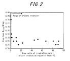
- FIG. 2 shows the relationship between iron loss and the area ratio of irradiation marks within the irradiation region of the beam
- FIGS. 3 and 4 show the relationship between insulation properties before re-forming and the area ratio of irradiation marks within the irradiation region of the beam.
- the steel sheet can be provided with a sufficient effect of reducing iron loss.
- the area ratio of the irradiation mark within the irradiation region of the beam is 2 % or more
- the steel sheet can be provided with a sufficient effect of reducing iron loss.
- FIG. 2 shows that a sufficient amount of thermal strain can be provided locally by beam irradiation in a steel sheet in which the area ratio of the irradiation mark is 2 % or more.
- FIG. 5 shows the relationship between insulation properties before and after re-forming and the area ratio of protrusions of 1.5 ⁇ m or more at the edge of the irradiation mark region in a sample for which the area ratio of the irradiation mark within the irradiation region of the beam is from 2 % to 20 %. It is clear that while insulation properties are generally good, the withstand voltage before re-forming reduces when the area ratio of protrusions of 1.5 ⁇ m or more within a surrounding portion of an irradiation mark exceeds 60 %. It is thought that when a protrusion of 1.5 ⁇ m or more is present on the surface, then as shown in FIG. 5 , the insulation becomes easily damaged due to the distance between the electrode and the steel sheet being reducing by an amount equal to the protrusion at the time of withstand voltage measurement, so that the electric potential becomes concentrated.
- FIG. 6 shows a study of the relationship between insulation properties before and after re-forming and the area ratio of protrusions of 1.5 ⁇ m or more within a surrounding portion of an irradiation mark in a sample for which the area ratio of the irradiation mark within the irradiation region of the beam is from over 20 % to 100 %.
- the withstand voltage before re-forming is generally small. Furthermore, even after re-forming, the increase in the withstand voltage is small for an application amount of 1 g/m 2 when the area ratio of protrusions of 1.5 ⁇ m or more at the edge of the irradiation mark region exceeds 60 %. It is thought that when protrusions of 1.5 ⁇ m or more were present on the surface, the protrusions were not completely eliminated by a small amount of re-forming, and insulation was not regained.
- FIG. 7 shows a study of the relationship between insulation properties before and after re-forming and the area ratio of a portion in which the steel substrate is exposed in an irradiation mark in a sample for which the area ratio of the irradiation mark within the irradiation region of the beam is from 2 % to 20 % and the area ratio of protrusions of 1.5 ⁇ m or more is 60 % or less. It is clear that while insulation properties are generally good, the withstand voltage before re-forming is particularly large when the area ratio of a portion in which the steel substrate is exposed in an irradiation mark is 90 % or less.
- FIG. 8 shows a study of the relationship between insulation properties before and after re-forming and the area ratio of a portion in which the steel substrate is exposed in an irradiation mark in a sample for which the area ratio of the irradiation mark within the irradiation region of the beam is from over 20 % to 100 % and the area ratio of protrusions of 1.5 ⁇ m or more is 60 % or less.
- the withstand voltage before re-forming is generally small. In particular, upon exceeding 90 %, it is clear that the withstand voltage reduces. Furthermore, focusing on the amount of increase in the withstand voltage from before to after re-forming, it is clear that the amount of increase is small in a region smaller than 30 %.
- the properties of the irradiation mark region were restricted to the above conditions (a) to (c).
- the inventors developed a new grain-oriented electrical steel sheet that has excellent insulation properties without re-forming, or that has excellent insulation properties after re-forming with a thin coating, and that makes iron loss properties compatible with insulation properties with only re-forming with a thin coating.
- a high-energy beam such as laser irradiation or electron beam irradiation that can apply a large energy by focusing the beam diameter is adopted.
- a magnetic domain refinement technique other than laser irradiation and electron beam irradiation plasma jet irradiation is well known. In the present invention, however, laser irradiation or electron beam irradiation is preferable in order to achieve desired iron loss.
- the form of laser oscillation is not particularly limited and may be fiber, CO 2 , YAG, or the like, yet a continuous irradiation type laser is adopted.
- Pulse oscillation type laser irradiation such as a Q-switch type, irradiates a large amount of energy at once, resulting in great damage to the coating and making it difficult to keep the irradiation mark within the restrictions of the present invention when the magnetic domain refinement effect is in a sufficient range.
- the beam diameter is a value uniquely set from the collimator, the lens focal distance, and the like in the optical system.
- the beam diameter may be in the shape of a circle or an ellipse.
- P/V indicates the energy heat input per unit length. At 10 W ⁇ s/m or less, the heat input is small, and a sufficient magnetic domain refinement effect is not achieved. Conversely, at 35 W ⁇ s/m or more, the heat input is large, and damage to the coating is too great. Therefore, the properties of the irradiation mark region according to the present invention are not achieved.
- the beam diameter d decreases, the heat input per unit area increases, and the damage to the coating becomes great.
- the properties of the irradiation mark region according to the present invention are not achieved.
- the upper limit is not particularly prescribed, yet to obtain a sufficient magnetic domain refinement effect in the above P/V range, approximately 0.85 mm or less is preferable.
- the properties of the irradiation mark preferably satisfy the above conditions. 40 kV ⁇ E ⁇ 150 kV 6 mA ⁇ I ⁇ 12 mA V ⁇ 40 m / s
- the magnetic domain refinement effect increases, yet the heat input per unit length grows large, making it difficult to achieve the irradiation mark properties of the present invention. Conversely, setting the acceleration voltage E and the beam current I to be smaller than the above ranges is not appropriate, since the magnetic domain refinement effect grows small.
- the pressure in the working chamber in which the steel sheet is irradiated with the electron beam is preferably 2 Pa or less. If the degree of vacuum is lower (i.e. if pressure is greater), the beam loses focus due to residual gas along the way from the electron gun to the steel sheet, thus reducing the magnetic domain refinement effect.
- the beam diameter changes depending on factors such as the acceleration voltage, the beam current, and the degree of vacuum, no suitable range is particularly designated, yet a range of approximately 0.10 mm to 0.40 mm is preferable. This diameter is prescribed for the half width of the energy profile using a known slit method.
- the steel sheets may be irradiated continuously or in a dot-sequence manner.
- a method to apply strain in a dot-sequence is realized by repeating a process to scan the beam rapidly while stopping for dots at predetermined intervals of time, continuously irradiating the steel sheet with the beam for each dot for an amount of time conforming to the present invention before restarting the scan.
- a large capacity amplifier may be used to vary the diffraction voltage of the electron beam.
- the interval between dots is preferably 0.40 mm or less, since the magnetic domain refinement effect decreases if the interval is too large.
- the interval in the rolling direction between irradiation rows for magnetic domain refinement by electron beam irradiation is unrelated to the steel sheet properties prescribed by the present invention, yet in order to increase the magnetic domain refinement effect, this interval is preferably 3 mm to 5 mm.
- the direction of irradiation is preferably 30° or less with respect to a direction orthogonal to the rolling direction and is more preferably orthogonal to the rolling direction.
- the method for manufacturing the grain-oriented electrical steel sheet of the present invention is not particularly limited, yet the following describes a recommended preferable chemical composition and a method for manufacturing apart from the points of the present invention.
- the chemical composition may contain appropriate amounts of Al and N in the case where an inhibitor, e.g. an AIN-based inhibitor, is used or appropriate amounts of Mn and Se and/or S in the case where an MnS ⁇ MnSe-based inhibitor is used.
- an inhibitor e.g. an AIN-based inhibitor
- Mn and Se and/or S in the case where an MnS ⁇ MnSe-based inhibitor is used.
- these inhibitors may also be used in combination.
- Al, N, S and Se are: Al: 0.01 mass% to 0.065 mass%; N: 0.005 mass% to 0.012 mass%; S: 0.005 mass% to 0.03 mass%; and Se: 0.005 mass% to 0.03 mass%, respectively.
- the present invention is applicable to a grain-oriented electrical steel sheet having limited contents of Al, N, S and Se without using an inhibitor.
- the contents of Al, N, S and Se are preferably limited to Al: 100 mass ppm or less, N: 50 mass ppm or less, S: 50 mass ppm or less, and Se: 50 mass ppm or less, respectively.
- the C content is preferably 0.08 mass% or less. It is not necessary to set a particular lower limit on the C content, because secondary recrystallization is enabled by a material not containing C.
- Silicon (Si) is an element that is effective for enhancing electrical resistance of steel and improving iron loss properties thereof. If the content is less than 2.0 mass%, however, a sufficient iron loss reduction effect is difficult to achieve. On the other hand, a content exceeding 8.0 mass% significantly deteriorates formability and also decreases the flux density of the steel. Therefore, the Si content is preferably in a range of 2.0 mass% to 8.0 mass%.
- Manganese (Mn) is preferably added to achieve better hot workability of steel. However, this effect is inadequate when the Mn content in steel is below 0.005 mass%. On the other hand, Mn content in steel above 1.0 mass% deteriorates magnetic flux of a product steel sheet. Accordingly, the Mn content is preferably in a range of 0.005 mass% to 1.0 mass%.
- the following elements may also be included as deemed appropriate for improving magnetic properties.
- Nickel (Ni) is an element that is useful for improving the texture of a hot rolled steel sheet for better magnetic properties thereof.
- Ni content in steel below 0.03 mass% is less effective for improving magnetic properties, while Ni content in steel above 1.5 mass% makes secondary recrystallization of the steel unstable, thereby deteriorating the magnetic properties thereof.
- Ni content is preferably in a range of 0.03 mass% to 1.5 mass%.
- tin (Sn), antimony (Sb), copper (Cu), phosphorus (P), chromium (Cr), and molybdenum (Mo) are useful elements in terms of improving magnetic properties of steel.
- each of these elements becomes less effective for improving magnetic properties of the steel when contained in steel in an amount less than the aforementioned lower limit and inhibits the growth of secondary recrystallized grains of the steel when contained in steel in an amount exceeding the aforementioned upper limit.
- each of these elements is preferably contained within the respective ranges thereof specified above.
- the balance other than the above-described elements is Fe and incidental impurities that are incorporated during the manufacturing process.
- Steel material adjusted to the above preferable chemical composition may be formed into a slab by normal ingot casting or continuous casting, or a thin slab or thinner cast steel with a thickness of 100 mm or less may be manufactured by direct continuous casting.
- the slab may be either heated by a normal method for hot rolling or directly subjected to hot rolling after casting without being heated.
- a thin slab or thinner cast steel may be either hot rolled or directly used in the next process by omitting hot rolling. After performing hot band annealing as necessary, the material is formed as a cold rolled sheet with the final sheet thickness by cold rolling once, or two or more times with intermediate annealing therebetween.
- the cold-rolled sheet may be subjected to nitriding treatment with an increase in the nitrogen amount of 50 ppm or more and 1000 ppm or less.
- nitriding treatment when performing magnetic domain refining treatment by laser irradiation or electron beam irradiation after the nitriding treatment, damage to the coating tends to increase as compared to when the nitriding treatment is not performed, and the corrosion resistance and insulation properties after re-forming worsen significantly. Accordingly, application of the present invention is particularly effective when performing nitriding treatment. While the reason is unclear, it is considered that the structure of the base film formed during final annealing changes, exacerbating exfoliation of the film.
- the coating liquid A below was then applied to the steel sheets, and an insulating coating was formed by baking at 800 °C. Subsequently, magnetic domain refining treatment was applied by performing continuous fiber laser irradiation, or Q switch pulse laser irradiation, on the insulating coating in a direction perpendicular to the rolling direction, and at 3 mm intervals in the rolling direction. As a result, material with a magnetic flux density B 8 of 1.92 T to 1.94 T was obtained.
- the irradiation region was observed with an electron microscope to verify the properties of the irradiation mark. Furthermore, in the same way as above, the interlaminar current and the withstand voltage were measured. Subsequently, as re-forming treatment, 1 g/m 2 of the coating liquid B below was applied to both sides of the steel sheets, and the steel sheets were baked in a range at which the magnetic domain refinement effect is not impaired due to release of strain. The interlaminar current and withstand voltage were then once again measured in the same way as described above. Furthermore, the 1.7 T and 50 Hz iron loss W 17/50 were measured in a single sheet tester (SST). Table 1 summarizes the measurement results.
- the steel sheets satisfying the ranges of the irradiation mark properties of the present invention satisfied a shipping standard of 0.2 A or less for interlaminar resistance and 60 V or more for withstand voltage.
- Example 2 Cold-rolled sheets for grain-oriented electrical steel sheets, rolled to a final sheet thickness of 0.23 mm and containing similar components to Example 1 were decarburized. After primary recrystallization annealing, an annealing separator containing MgO as the primary component was applied, and final annealing including a secondary recrystallization process and a purification process was performed to yield grain-oriented electrical steel sheets with a forsterite film. The coating liquid A in the above-described Example 1 was then applied to the steel sheets, and an insulating coating was formed by baking at 800 °C.
- magnetic domain refining treatment was applied by dot-sequence irradiation or continuous irradiation, with an electron beam at a degree of vacuum in the working chamber of 1 Pa, on the insulating coating in a direction perpendicular to the rolling direction, and at 3 mm intervals in the rolling direction.
- material with a magnetic flux density B 8 of 1.92 T to 1.94 T was obtained.
- the irradiation region was observed with an electron microscope to verify the properties of the irradiation mark. Furthermore, in the same way as above, the interlaminar current and the withstand voltage were measured. Subsequently, as re-forming treatment, 1 g/m 2 of the coating liquid B in the above-described Example 1 was applied to both sides of the steel sheets, and the steel sheets were baked in a range at which the magnetic domain refinement effect is not impaired due to release of strain. The interlaminar current and the withstand voltage were then measured again. Furthermore, the 1.7 T and 50 Hz iron loss W 17/50 was measured in a single sheet tester (SST). Table 2 summarizes the measurement results.
- the steel sheets satisfying the ranges of the irradiation mark properties of the present invention satisfied a shipping standard of 0.2 A or less for interlaminar resistance and 60 V or more for withstand voltage.
- Cold-rolled sheets for grain-oriented electrical steel sheets, rolled to a final sheet thickness of 0.23 mm and containing Si: 3.3 mass%, Mn: 0.08 mass%, Cu: 0.05 mass%, Al: 0.002 mass%, S: 0.001 mass%, C: 0.06 mass%, and N: 0.002 mass% were decarburized.
- nitrogen treatment was applied by subjecting a portion of the cold-rolled sheets as a coil to batch salt bath treatment to increase the amount of N in the steel by 700 ppm.
- Example 2 An annealing separator containing MgO as the primary component was applied, and final annealing including a secondary recrystallization process and a purification process was performed to yield grain-oriented electrical steel sheets with a forsterite film.
- the coating liquid A described above in Example 1 was then applied to the grain-oriented electrical steel sheets, and an insulating coating was formed by baking at 800 °C.
- magnetic domain refining treatment was applied by dot-sequence irradiation or continuous irradiation, with an electron beam at a degree of vacuum in the working chamber of 1 Pa, on the insulating coating in a direction perpendicular to the rolling direction, and at 3 mm intervals in the rolling direction.
- material with a magnetic flux density B 8 of 1.92 T to 1.95 T was obtained.
- the electron beam irradiation portion was first observed under an electron microscope to verify the properties of the irradiation mark region. Furthermore, in the same way as above, the interlaminar current and the withstand voltage were measured. Subsequently, as re-forming treatment, 1 g/m 2 of the coating liquid B in the above-described Example 1 was applied to both sides of the steel sheets, and the steel sheets were baked in a range at which the magnetic domain refinement effect is not impaired due to release of strain. The interlaminar current and the withstand voltage were then measured again. Furthermore, the 1.7 T, 50 Hz iron loss W 17/50 was measured in a single sheet tester (SST). Table 3 summarizes the measurement results.
- Table 3 shows that for the nitriding treatment-subjected material outside of the range of the present invention, both the insulation properties and corrosion resistance before and after re-forming were worse than when not performing nitriding treatment.
- the nitriding treatment-subjected material within the range of the present invention had equivalent insulation properties and corrosion resistance as when not performing nitriding treatment, demonstrating the usefulness of adopting the present invention.
Abstract
Description
- The present invention relates to a grain-oriented electrical steel sheet advantageously utilized for an iron core of a transformer or the like, and to a method for manufacturing the same.
- A grain-oriented electrical steel sheet is mainly utilized as an iron core of a transformer and is required to exhibit superior magnetization characteristics, in particular low iron loss.
- In this regard, it is important to highly accord secondary recrystallized grains of a steel sheet with (110)[001] orientation, i.e. the "Goss orientation", and reduce impurities in a product steel sheet. Furthermore, since there are limits on controlling crystal grain orientations and reducing impurities, a technique has been developed to introduce non-uniformity into a surface of a steel sheet by physical means to subdivide the width of a magnetic domain to reduce iron loss, i.e. a magnetic domain refining technique.
- For example,
JP S57-2252 B2 JP H6-072266 B2 - Thermal strain application-based magnetic domain refinement techniques such as laser beam irradiation and electron beam irradiation have the problem that insulating coating on the steel sheet is damaged by sudden and local thermal application, causing the insulation properties such as interlaminar resistance and withstand voltage, as well as corrosion resistance, to worsen. Therefore, after laser beam irradiation or electron beam irradiation, re-forming is performed on the steel sheet by applying an insulating coating again to the steel sheet and baking the insulating coating in a temperature range at which thermal strain is not eliminated. Re-forming, however, leads to problems such as increased costs due to an additional process, deterioration of magnetic properties due to a worse stacking factor, and the like.
- A problem also occurs in that if the damage to the coating is severe, the insulation properties and corrosion resistance cannot be regained even by re-forming, and re-forming simply thickens the coating amount. Thickening the coating amount by re-forming not only worsens the stacking factor but also damages the adhesion property and the appearance of the steel sheet, thus significantly reducing the value of the product.
- Against this background, techniques for applying strain while suppressing damage to the insulating coating have been proposed, for example in
JP S62-49322 B2 JP H5-32881 B2 JP 3361709 B2 JP 4091749 B2 PTL 1 to 5 adopt approaches such as blurring the focus of the beam or suppressing the beam power in order to reduce the actual amount of thermal strain that is applied to the steel sheet. Even if the insulation properties of the steel sheet are maintained, however, the amount of iron loss reduction ends up decreasing. PTL 6 discloses a method for reducing the iron loss while maintaining insulation properties by irradiating both sides of a steel sheet with a laser, yet this method is not advantageous in terms of cost, since irradiating both sides of the steel sheet increases the number of treatment steps. -
- PTL 1:
JP S57-2252 B2 - PTL 2:
JP H6-072266 B2 - PTL 3:
JP S62-49322 B2 - PTL 4:
JP H5-32881 B2 - PTL 5:
JP 3361709 B2 - PTL 6:
JP 4091749 B2 - It is an object of the present invention to provide a grain-oriented electrical steel sheet, on which magnetic domain refining treatment by strain application has been performed, having an insulating coating with excellent insulation properties and corrosion resistance.
- In order to achieve reduced iron loss by magnetic domain refining treatment, it is essential to provide sufficient thermal strain locally on the steel sheet after final annealing. The principle behind a reduction in iron loss through the application of strain is as follows.
- First, upon applying strain to a steel sheet, a closure domain is generated originating from the strain. Generation of the closure domain increases the magnetostatic energy of the steel sheet, yet the 180° magnetic domain is subdivided to lower the increased magnetostatic energy, and the iron loss in the rolling direction is reduced. On the other hand, the closure domain causes pinning of the domain wall, suppressing displacement thereof, and leads to increased hysteresis loss. Therefore, strain is preferably applied locally in a range at which the effect of reducing iron loss is not impaired.
- As described above, however, irradiating with a locally strong laser beam or electron beam damages the coating (forsterite film and insulating tension coating formed thereon). Therefore, it becomes necessary to re-form an insulating coating on the steel sheet in order to compensate for the damage. In particular, when the coating is damaged to a great degree, the amount of re-forming needs to be increased in order to regain the insulation properties. The stacking factor upon use as an iron core of a transformer is thus greatly reduced, resulting in deteriorated magnetic properties.
- By examining the degree of damage to the coating in detail, i.e. the relationship between the properties of the irradiation mark region and the iron loss and insulation properties before and after re-forming, the inventors of the present invention developed a grain-oriented electrical steel sheet for which re-forming is not performed, or on which an insulating coating is only thinly re-formed, that makes iron loss properties compatible with insulation properties, thereby completing the present invention.
- Specifically, primary features of the present invention are as follows.
- (1) A grain-oriented electrical steel sheet, linear strain having been applied thereto by irradiation with a high-energy beam, the linear strain extending in a direction that intersects a rolling direction of the steel sheet, wherein
an area ratio of an irradiation mark within an irradiation region of the high-energy beam is 2 % or more and 20 % or less, an area ratio of a protrusion with a diameter of 1.5 µm or more within a surrounding portion of the irradiation mark is 60 % or less, and an area ratio of an exposed portion of steel substrate in the irradiation mark is 90 % or less. - (2) The grain-oriented electrical steel sheet according to (1), comprising an insulating coating formed after the irradiation with the high-energy beam.
- (3) The grain-oriented electrical steel sheet according to (1) or (2), wherein the direction in which the linear strain extends forms an angle of 30° or less with a direction orthogonal to the rolling direction of the steel sheet.
- (4) A grain-oriented electrical steel sheet, linear strain having been applied thereto by irradiation with a high-energy beam, the linear strain extending in a direction that intersects a rolling direction of the steel sheet, wherein
an area ratio of an irradiation mark within an irradiation region of the high-energy beam exceeds 20 %, an area ratio of a protrusion with a diameter of 1.5 µm or more within a surrounding portion of the irradiation mark is 60 % or less, an area ratio of an exposed portion of steel substrate in the irradiation mark is 30 % or more and 90 % or less, and an insulating coating is formed after the irradiation with the high-energy beam. - (5) A method for manufacturing a grain-oriented electrical steel sheet, comprising:
- in manufacturing the grain-oriented electrical steel sheet according to (1) by applying, to a grain-oriented electrical steel sheet after final annealing, linear strain extending in a direction that intersects a rolling direction of the steel sheet,
- applying the linear strain by irradiating, with a continuous laser, a surface of the grain-oriented electrical steel sheet after final annealing.
- (6) A method for manufacturing a grain-oriented electrical steel sheet, comprising:
- in manufacturing the grain-oriented electrical steel sheet according to (1) by applying, to a grain-oriented electrical steel sheet after final annealing, linear strain extending in a direction that intersects a rolling direction of the steel sheet,
- applying the linear strain by irradiating, with an electron beam, a surface of the grain-oriented electrical steel sheet after final annealing.
- (7) A method for manufacturing a grain-oriented electrical steel sheet, comprising:
- in manufacturing the grain-oriented electrical steel sheet according to (4) by applying, to a grain-oriented electrical steel sheet after final annealing, linear strain extending in a direction that intersects a rolling direction of the steel sheet,
- applying the linear strain by irradiating, with a continuous laser, a surface of the grain-oriented electrical steel sheet after final annealing.
- (8) A method for manufacturing a grain-oriented electrical steel sheet, comprising:
- in manufacturing the grain-oriented electrical steel sheet according to (4) by applying, to a grain-oriented electrical steel sheet after final annealing, linear strain extending in a direction that intersects a rolling direction of the steel sheet,
- applying the linear strain by irradiating, with an electron beam, a surface of the grain-oriented electrical steel sheet after final annealing.
- (9) The method for manufacturing a grain-oriented electrical steel sheet according to any one of (5) to (8), comprising:
- subjecting a cold-rolled sheet for grain-oriented electrical steel to primary recrystallization annealing and then final annealing; and
- irradiating the grain-oriented electrical steel sheet after final annealing with the high-energy beam,
- wherein the cold-rolled sheet is subjected to nitriding treatment during or after the primary recrystallization annealing.
- According to the present invention, it is possible to provide a low-iron loss grain-oriented electrical steel sheet, on which magnetic domain refining treatment by strain application has been performed, having coating properties with excellent insulation properties and corrosion resistance, without re-forming or after re-forming with a thin coating.
- The present invention will be further described below with reference to the accompanying drawings, wherein:
-
FIG. 1 illustrates irradiation marks on a steel sheet; -
FIG. 2 is a graph showing the relationship between iron loss and the area ratio of irradiation marks within the irradiation region of the beam; -
FIG. 3 is a graph showing the relationship between insulation properties before re-forming and the area ratio of irradiation marks within the irradiation region of the beam; -
FIG. 4 is a graph showing the relationship between insulation properties before re-forming and the area ratio of irradiation marks within the irradiation region of the beam; -
FIG. 5 is a graph showing the relationship between insulation properties before and after re-forming and the area ratio of protrusions of 1.5 µm or more within a surrounding portion of an irradiation mark when the area ratio of the irradiation mark within the irradiation region of the beam is from 2 % to 20 %; -
FIG. 6 is a graph showing the relationship between insulation properties before and after re-forming and the area ratio of protrusions of 1.5 µm or more within a surrounding portion of an irradiation mark when the area ratio of the irradiation mark within the irradiation region of the beam is from 21 % to 100 %; -
FIG. 7 is a graph showing the relationship between insulation properties before and after re-forming and the area ratio of a portion in which the steel substrate is exposed in an irradiation mark when the area ratio of the irradiation mark within the irradiation region of the beam is from 2 % to 20 % and the area ratio of protrusions of 1.5 µm or more is 60 % or less; and -
FIG. 8 is a graph showing the relationship between insulation properties before and after re-forming and the area ratio of a portion in which the steel substrate is exposed in an irradiation mark when the area ratio of irradiation marks within the irradiation region of the beam is from 21 % to 100 % and the area ratio of protrusions of 1.5 µm or more is 60 % or less. - As described above, in the grain-oriented electrical steel sheet according to the present invention, the steel sheet properties after beam irradiation need to be restricted to requirements (a) to (c) below. Each requirement is described in detail below.
- (a) the area ratio of irradiation mark(s) within an irradiation region of the high-energy beam is 2 % or more and 20 % or less, or exceeds 20 %
- (b) the area ratio of protrusion(s) with a diameter of 1.5 µm or more within a surrounding portion of an irradiation mark is 60 % or less
- (c) the area ratio of exposed portion(s) of the steel substrate in an irradiation mark is 90 % or less (and 30 % or more in the case of (a) exceeding 20 %)
- First, before describing the prescriptions in (a) to (c), the definition of each restriction is explained.
-
FIG. 1(a) shows anirradiation region 2 of a high-energy beam (laser beam or electron beam) andirradiation marks 3 when irradiating acoating 1 of a steel sheet surface linearly with the beam, andFIG. 1(b) similarly shows the case of irradiating in a dot-sequence manner. Within portions irradiated with a laser beam or electron beam, the irradiation marks 3 refer to portions in which thecoating 1 has melted or peeled off under observation with an optical microscope or an electron microscope. Theirradiation region 2 of the beam indicates a linear region yielded by connecting the irradiation marks 3 at the same width in the rolling direction. The width is the maximum width of the irradiation marks 3 in the rolling direction. In the case of continuous linear irradiation, the definition of theirradiation region 2 of the beam in the present invention is the same as the actual region irradiated with the beam, yet in the case of dot-sequence irradiation, each portion between dots that is not actually irradiated with the beam is included. The area ratio of the irradiation marks 3 within theirradiation region 2 as defined above is restricted by the area ratio. - The surrounding portion of the irradiation mark indicates a region within 5 µm from the edge of the above-defined
irradiation mark 3 outward in the radial direction. In this region, the area ratio where any protrusions with a height of 1.5 µm or more are present is defined as the area ratio of protrusions of 1.5 µm or more within a surrounding portion of an irradiation mark. The area ratio of the protrusions can be measured by measuring surface unevenness with a laser microscope, or by cross-sectional observation of the irradiation mark region with an optical microscope or an electron microscope. - In the above-defined
irradiation mark 3, the area ratio of a portion in which the steel substrate is exposed is defined as the area ratio of a portion in which the steel substrate is exposed in the irradiation mark. Whether the steel substrate is exposed is determined based on EPMA, electron microscope observation, or the like. For example, under reflected electron image observation of theirradiation mark 3, a portion in which steel is exposed is observed as a bright contrast, clearly distinguishable from other portions where the coating remains. - Note that all of the parameters were calculated by observing dot-sequences at five or more locations in a sample measuring 100 mm wide by 400 mm in the rolling direction and then taking the average.
- Under a variety of laser irradiation conditions, magnetic domain refining treatment was performed on 0.23 mm thick grain-oriented electrical steel sheets (B8 = 1.93 T), and samples were used in which each of the following had been changed: area ratio of irradiation marks within an irradiation region of the beam, area ratio of protrusions of 1.5 µm or more within a surrounding portion of an irradiation mark, and area ratio of a portion in which the steel substrate is exposed in the irradiation mark. The following describes, in detail, the results of examining the relationship between these parameters and the iron loss and insulation properties and before and after re-forming, along with the effect of each parameter.
- Note that in the experiment, the measurement of interlaminar resistance/current and of withstand voltage was performed as described below.
- Measurement was performed in conformance with the A method among the measurement methods for an interlaminar resistance test listed in JIS C2550. The total current flowing to the terminal was considered to be the interlaminar resistance/current.
- One side of an electrode was connected to an edge of a sample steel substrate, and the other side connected to a pole with 25 mm φ and mass of 1 kg. The pole was placed on the surface of the sample, and voltage was gradually applied thereto. The voltage at the time of electrical breakdown was then read. By changing the location of the pole placed on the surface of the sample, measurement was made at five locations. The average was considered to be the measurement value.
- Re-forming of the insulating coating was performed by applying 1 g/m2 of an insulating coating mainly including aluminum phosphate and chromic acid to both sides after laser irradiation and then baking in a temperature range at which the magnetic domain refinement effect is not impaired due to release of strain.
-
FIG. 2 shows the relationship between iron loss and the area ratio of irradiation marks within the irradiation region of the beam, andFIGS. 3 and 4 show the relationship between insulation properties before re-forming and the area ratio of irradiation marks within the irradiation region of the beam. - As shown in
FIG. 2 , if the area ratio of the irradiation mark within the irradiation region of the beam is 2 % or more, the steel sheet can be provided with a sufficient effect of reducing iron loss. As described above, in order to achieve a sufficient effect of reducing iron loss, it is important to provide a sufficient amount of thermal strain locally. In other words,FIG. 2 shows that a sufficient amount of thermal strain can be provided locally by beam irradiation in a steel sheet in which the area ratio of the irradiation mark is 2 % or more. - Furthermore, from the results shown in
FIGS. 3 and 4 , it is clear that when the area ratio of the irradiation mark within the irradiation region of the beam is 20 % or less, the degree of damage to the coating is small, and therefore sufficient insulation properties are obtained even without re-forming. - On the other hand, when the area ratio of the irradiation mark exceeds 20 %, as described below, the damage to the coating is great, and insulation properties cannot be guaranteed without re-forming.
-
FIG. 5 shows the relationship between insulation properties before and after re-forming and the area ratio of protrusions of 1.5 µm or more at the edge of the irradiation mark region in a sample for which the area ratio of the irradiation mark within the irradiation region of the beam is from 2 % to 20 %. It is clear that while insulation properties are generally good, the withstand voltage before re-forming reduces when the area ratio of protrusions of 1.5 µm or more within a surrounding portion of an irradiation mark exceeds 60 %. It is thought that when a protrusion of 1.5 µm or more is present on the surface, then as shown inFIG. 5 , the insulation becomes easily damaged due to the distance between the electrode and the steel sheet being reducing by an amount equal to the protrusion at the time of withstand voltage measurement, so that the electric potential becomes concentrated. -
FIG. 6 shows a study of the relationship between insulation properties before and after re-forming and the area ratio of protrusions of 1.5 µm or more within a surrounding portion of an irradiation mark in a sample for which the area ratio of the irradiation mark within the irradiation region of the beam is from over 20 % to 100 %. The withstand voltage before re-forming is generally small. Furthermore, even after re-forming, the increase in the withstand voltage is small for an application amount of 1 g/m2 when the area ratio of protrusions of 1.5 µm or more at the edge of the irradiation mark region exceeds 60 %. It is thought that when protrusions of 1.5 µm or more were present on the surface, the protrusions were not completely eliminated by a small amount of re-forming, and insulation was not regained. -
FIG. 7 shows a study of the relationship between insulation properties before and after re-forming and the area ratio of a portion in which the steel substrate is exposed in an irradiation mark in a sample for which the area ratio of the irradiation mark within the irradiation region of the beam is from 2 % to 20 % and the area ratio of protrusions of 1.5 µm or more is 60 % or less. It is clear that while insulation properties are generally good, the withstand voltage before re-forming is particularly large when the area ratio of a portion in which the steel substrate is exposed in an irradiation mark is 90 % or less. - On the other hand,
FIG. 8 shows a study of the relationship between insulation properties before and after re-forming and the area ratio of a portion in which the steel substrate is exposed in an irradiation mark in a sample for which the area ratio of the irradiation mark within the irradiation region of the beam is from over 20 % to 100 % and the area ratio of protrusions of 1.5 µm or more is 60 % or less. The withstand voltage before re-forming is generally small. In particular, upon exceeding 90 %, it is clear that the withstand voltage reduces. Furthermore, focusing on the amount of increase in the withstand voltage from before to after re-forming, it is clear that the amount of increase is small in a region smaller than 30 %. Upon observing the irradiation mark region after re-forming in a sample with an area ratio of a portion in which the steel substrate is exposed of less than 30 %, multiple cracks and holes were visible in the coating surface, and it was clear that coating formation did not proceed well. While the reason is uncertain, it is considered that upon a reduction in the exposed portion of the steel substrate, the wettability of the irradiation mark region when applying the coating liquid in the irradiation mark region worsens, resulting in the occurrence of cracks and holes. - In light of the above experiment results, the properties of the irradiation mark region were restricted to the above conditions (a) to (c). By placing such restrictions, the inventors developed a new grain-oriented electrical steel sheet that has excellent insulation properties without re-forming, or that has excellent insulation properties after re-forming with a thin coating, and that makes iron loss properties compatible with insulation properties with only re-forming with a thin coating.
- Next, a method for manufacturing a steel sheet under the above requirements is described.
- First, as a magnetic domain refinement technique, a high-energy beam such as laser irradiation or electron beam irradiation that can apply a large energy by focusing the beam diameter is adopted. As a magnetic domain refinement technique other than laser irradiation and electron beam irradiation, plasma jet irradiation is well known. In the present invention, however, laser irradiation or electron beam irradiation is preferable in order to achieve desired iron loss.
- These magnetic domain refinement techniques are described in order, starting with laser irradiation.
- The form of laser oscillation is not particularly limited and may be fiber, CO2, YAG, or the like, yet a continuous irradiation type laser is adopted. Pulse oscillation type laser irradiation, such as a Q-switch type, irradiates a large amount of energy at once, resulting in great damage to the coating and making it difficult to keep the irradiation mark within the restrictions of the present invention when the magnetic domain refinement effect is in a sufficient range. The beam diameter is a value uniquely set from the collimator, the lens focal distance, and the like in the optical system. The beam diameter may be in the shape of a circle or an ellipse.
- At the time of laser irradiation, when the average laser power P (W), beam scanning rate V (m/s), and beam diameter d (mm) are within the ranges below, the above conditions (a) to (c) are preferably satisfied.


- P/V indicates the energy heat input per unit length. At 10 W·s/m or less, the heat input is small, and a sufficient magnetic domain refinement effect is not achieved. Conversely, at 35 W·s/m or more, the heat input is large, and damage to the coating is too great. Therefore, the properties of the irradiation mark region according to the present invention are not achieved.
- When the heat input is the same, damage to the coating lessens as the beam scanning rate V is slower. The reason is that when the scanning rate is low, the rate of diffusion of heat provided by the beam irradiation increases, and the energy received by the steel sheet immediately below the beam decreases. Upon exceeding 30 m/s, the damage to the coating becomes great, and the properties of the irradiation mark region according to the present invention are not achieved. The lower limit on the rate is not particularly prescribed, but from the perspective of productivity, 5 m/s or more is preferable.
- As the beam diameter d decreases, the heat input per unit area increases, and the damage to the coating becomes great. In the above P/V range, when d is 0.20 mm or less, the properties of the irradiation mark region according to the present invention are not achieved. The upper limit is not particularly prescribed, yet to obtain a sufficient magnetic domain refinement effect in the above P/V range, approximately 0.85 mm or less is preferable.
- Next, conditions for magnetic domain refinement by electron beam irradiation are described.
- At the time of electron beam irradiation, when the acceleration voltage E (kV), beam current I (mA), and beam scanning rate V (m/s) are within the ranges below, the properties of the irradiation mark preferably satisfy the above conditions.


- If the acceleration voltage E and the beam current I are larger than the above ranges, the magnetic domain refinement effect increases, yet the heat input per unit length grows large, making it difficult to achieve the irradiation mark properties of the present invention. Conversely, setting the acceleration voltage E and the beam current I to be smaller than the above ranges is not appropriate, since the magnetic domain refinement effect grows small.
- As with the laser above, when the heat input is the same, damage to the coating lessens as the beam scanning rate V is slower. At 40 m/s or more, the damage to the coating becomes great, and the properties of the irradiation mark region according to the present invention are not achieved. The lower limit on the scanning rate is not particularly prescribed, but from the perspective of productivity, 10 m/s or more is preferable.
- As for the degree of vacuum (pressure in the working chamber), the pressure in the working chamber in which the steel sheet is irradiated with the electron beam is preferably 2 Pa or less. If the degree of vacuum is lower (i.e. if pressure is greater), the beam loses focus due to residual gas along the way from the electron gun to the steel sheet, thus reducing the magnetic domain refinement effect.
- Since the beam diameter changes depending on factors such as the acceleration voltage, the beam current, and the degree of vacuum, no suitable range is particularly designated, yet a range of approximately 0.10 mm to 0.40 mm is preferable. This diameter is prescribed for the half width of the energy profile using a known slit method.
- The steel sheets may be irradiated continuously or in a dot-sequence manner. A method to apply strain in a dot-sequence is realized by repeating a process to scan the beam rapidly while stopping for dots at predetermined intervals of time, continuously irradiating the steel sheet with the beam for each dot for an amount of time conforming to the present invention before restarting the scan. In order to implement this process with electron beam irradiation, a large capacity amplifier may be used to vary the diffraction voltage of the electron beam. When irradiating in a dot-sequence manner, the interval between dots is preferably 0.40 mm or less, since the magnetic domain refinement effect decreases if the interval is too large.
- The interval in the rolling direction between irradiation rows for magnetic domain refinement by electron beam irradiation is unrelated to the steel sheet properties prescribed by the present invention, yet in order to increase the magnetic domain refinement effect, this interval is preferably 3 mm to 5 mm. Furthermore, the direction of irradiation is preferably 30° or less with respect to a direction orthogonal to the rolling direction and is more preferably orthogonal to the rolling direction.
- Other than the above points, the method for manufacturing the grain-oriented electrical steel sheet of the present invention is not particularly limited, yet the following describes a recommended preferable chemical composition and a method for manufacturing apart from the points of the present invention.
- In the present invention, the chemical composition may contain appropriate amounts of Al and N in the case where an inhibitor, e.g. an AIN-based inhibitor, is used or appropriate amounts of Mn and Se and/or S in the case where an MnS·MnSe-based inhibitor is used. Of course, these inhibitors may also be used in combination.
- In this case, preferred contents of Al, N, S and Se are: Al: 0.01 mass% to 0.065 mass%; N: 0.005 mass% to 0.012 mass%; S: 0.005 mass% to 0.03 mass%; and Se: 0.005 mass% to 0.03 mass%, respectively.
- The present invention is applicable to a grain-oriented electrical steel sheet having limited contents of Al, N, S and Se without using an inhibitor.
- In this case, the contents of Al, N, S and Se are preferably limited to Al: 100 mass ppm or less, N: 50 mass ppm or less, S: 50 mass ppm or less, and Se: 50 mass ppm or less, respectively.
- Other basic components and optionally added components are as follows.
- If the C content exceeds 0.08 mass%, it becomes difficult to reduce the C content to 50 mass ppm or less, at which point magnetic aging will not occur during the manufacturing process. Therefore, the C content is preferably 0.08 mass% or less. It is not necessary to set a particular lower limit on the C content, because secondary recrystallization is enabled by a material not containing C.
- Silicon (Si) is an element that is effective for enhancing electrical resistance of steel and improving iron loss properties thereof. If the content is less than 2.0 mass%, however, a sufficient iron loss reduction effect is difficult to achieve. On the other hand, a content exceeding 8.0 mass% significantly deteriorates formability and also decreases the flux density of the steel. Therefore, the Si content is preferably in a range of 2.0 mass% to 8.0 mass%.
- Manganese (Mn) is preferably added to achieve better hot workability of steel. However, this effect is inadequate when the Mn content in steel is below 0.005 mass%. On the other hand, Mn content in steel above 1.0 mass% deteriorates magnetic flux of a product steel sheet. Accordingly, the Mn content is preferably in a range of 0.005 mass% to 1.0 mass%.
- Furthermore, in addition to the above basic components, the following elements may also be included as deemed appropriate for improving magnetic properties.
- Nickel (Ni) is an element that is useful for improving the texture of a hot rolled steel sheet for better magnetic properties thereof. However, Ni content in steel below 0.03 mass% is less effective for improving magnetic properties, while Ni content in steel above 1.5 mass% makes secondary recrystallization of the steel unstable, thereby deteriorating the magnetic properties thereof. Thus, Ni content is preferably in a range of 0.03 mass% to 1.5 mass%.
- In addition, tin (Sn), antimony (Sb), copper (Cu), phosphorus (P), chromium (Cr), and molybdenum (Mo) are useful elements in terms of improving magnetic properties of steel. However, each of these elements becomes less effective for improving magnetic properties of the steel when contained in steel in an amount less than the aforementioned lower limit and inhibits the growth of secondary recrystallized grains of the steel when contained in steel in an amount exceeding the aforementioned upper limit. Thus, each of these elements is preferably contained within the respective ranges thereof specified above. The balance other than the above-described elements is Fe and incidental impurities that are incorporated during the manufacturing process.
- Steel material adjusted to the above preferable chemical composition may be formed into a slab by normal ingot casting or continuous casting, or a thin slab or thinner cast steel with a thickness of 100 mm or less may be manufactured by direct continuous casting. The slab may be either heated by a normal method for hot rolling or directly subjected to hot rolling after casting without being heated. A thin slab or thinner cast steel may be either hot rolled or directly used in the next process by omitting hot rolling. After performing hot band annealing as necessary, the material is formed as a cold rolled sheet with the final sheet thickness by cold rolling once, or two or more times with intermediate annealing therebetween. Subsequently, after subjecting the cold rolled sheet to primary recrystallization annealing (decarburizing annealing) and then final annealing, an insulating tension coating is applied, and the cold rolled sheet is subjected to flattening annealing to yield a grain-oriented electrical steel sheet with an insulating coating. Subsequently, magnetic domain refining treatment is performed by irradiating the grain-oriented electrical steel sheet with a laser or an electron beam. Furthermore, re-forming of the insulating coating is performed under the above requirements to yield a product according to the present invention.
- During or after the primary recrystallization annealing (decarburizing annealing), in order to strengthen the inhibitor function, the cold-rolled sheet may be subjected to nitriding treatment with an increase in the nitrogen amount of 50 ppm or more and 1000 ppm or less. In the case of performing this nitriding treatment, when performing magnetic domain refining treatment by laser irradiation or electron beam irradiation after the nitriding treatment, damage to the coating tends to increase as compared to when the nitriding treatment is not performed, and the corrosion resistance and insulation properties after re-forming worsen significantly. Accordingly, application of the present invention is particularly effective when performing nitriding treatment. While the reason is unclear, it is considered that the structure of the base film formed during final annealing changes, exacerbating exfoliation of the film.
- Cold-rolled sheets for grain-oriented electrical steel sheets, rolled to a final sheet thickness of 0.23 mm and containing Si: 3.25 mass%, Mn: 0.04 mass%, Ni: 0.01 mass%, Al: 60 mass ppm, S: 20 mass ppm, C: 250 mass ppm, O: 16 mass ppm, and N: 40 mass ppm were decarburized. After primary recrystallization annealing, an annealing separator containing MgO as the primary component was applied, and final annealing including a secondary recrystallization process and a purification process was performed to yield grain-oriented electrical steel sheets with a forsterite film. The coating liquid A below was then applied to the steel sheets, and an insulating coating was formed by baking at 800 °C. Subsequently, magnetic domain refining treatment was applied by performing continuous fiber laser irradiation, or Q switch pulse laser irradiation, on the insulating coating in a direction perpendicular to the rolling direction, and at 3 mm intervals in the rolling direction. As a result, material with a magnetic flux density B8 of 1.92 T to 1.94 T was obtained.
- The irradiation region was observed with an electron microscope to verify the properties of the irradiation mark. Furthermore, in the same way as above, the interlaminar current and the withstand voltage were measured. Subsequently, as re-forming treatment, 1 g/m2 of the coating liquid B below was applied to both sides of the steel sheets, and the steel sheets were baked in a range at which the magnetic domain refinement effect is not impaired due to release of strain. The interlaminar current and withstand voltage were then once again measured in the same way as described above. Furthermore, the 1.7 T and 50 Hz iron loss W17/50 were measured in a single sheet tester (SST). Table 1 summarizes the measurement results.
- Coating liquid A: liquid containing 100 cc of 20 % aqueous dispersion of colloidal silica, 60 cc of 50 % aqueous solution of aluminum phosphate, 15 cc of approximately 25 % aqueous solution of magnesium chromate, and 3 g of boric acid
- Coating liquid B: liquid containing 60 cc of 50 % aqueous solution of aluminum phosphate, 15 cc of approximately 25 % aqueous solution of magnesium chromate, 3 g of boric acid, and 100 cc of water (not including colloidal silica)
- As Table 1 shows, before re-forming, or after re-forming with a thin coating, the steel sheets satisfying the ranges of the irradiation mark properties of the present invention satisfied a shipping standard of 0.2 A or less for interlaminar resistance and 60 V or more for withstand voltage.

- Cold-rolled sheets for grain-oriented electrical steel sheets, rolled to a final sheet thickness of 0.23 mm and containing similar components to Example 1 were decarburized. After primary recrystallization annealing, an annealing separator containing MgO as the primary component was applied, and final annealing including a secondary recrystallization process and a purification process was performed to yield grain-oriented electrical steel sheets with a forsterite film. The coating liquid A in the above-described Example 1 was then applied to the steel sheets, and an insulating coating was formed by baking at 800 °C. Subsequently, magnetic domain refining treatment was applied by dot-sequence irradiation or continuous irradiation, with an electron beam at a degree of vacuum in the working chamber of 1 Pa, on the insulating coating in a direction perpendicular to the rolling direction, and at 3 mm intervals in the rolling direction. As a result, material with a magnetic flux density B8 of 1.92 T to 1.94 T was obtained.
- The irradiation region was observed with an electron microscope to verify the properties of the irradiation mark. Furthermore, in the same way as above, the interlaminar current and the withstand voltage were measured. Subsequently, as re-forming treatment, 1 g/m2 of the coating liquid B in the above-described Example 1 was applied to both sides of the steel sheets, and the steel sheets were baked in a range at which the magnetic domain refinement effect is not impaired due to release of strain. The interlaminar current and the withstand voltage were then measured again. Furthermore, the 1.7 T and 50 Hz iron loss W17/50 was measured in a single sheet tester (SST). Table 2 summarizes the measurement results.
- As Table 2 shows, before re-forming, or after re-forming with a thin coating, the steel sheets satisfying the ranges of the irradiation mark properties of the present invention satisfied a shipping standard of 0.2 A or less for interlaminar resistance and 60 V or more for withstand voltage.

- Cold-rolled sheets for grain-oriented electrical steel sheets, rolled to a final sheet thickness of 0.23 mm and containing Si: 3.3 mass%, Mn: 0.08 mass%, Cu: 0.05 mass%, Al: 0.002 mass%, S: 0.001 mass%, C: 0.06 mass%, and N: 0.002 mass% were decarburized. After primary recrystallization annealing, nitrogen treatment was applied by subjecting a portion of the cold-rolled sheets as a coil to batch salt bath treatment to increase the amount of N in the steel by 700 ppm. Subsequently, an annealing separator containing MgO as the primary component was applied, and final annealing including a secondary recrystallization process and a purification process was performed to yield grain-oriented electrical steel sheets with a forsterite film. The coating liquid A described above in Example 1 was then applied to the grain-oriented electrical steel sheets, and an insulating coating was formed by baking at 800 °C. Subsequently, magnetic domain refining treatment was applied by dot-sequence irradiation or continuous irradiation, with an electron beam at a degree of vacuum in the working chamber of 1 Pa, on the insulating coating in a direction perpendicular to the rolling direction, and at 3 mm intervals in the rolling direction. As a result, material with a magnetic flux density B8 of 1.92 T to 1.95 T was obtained.
- For the material obtained in this way, the electron beam irradiation portion was first observed under an electron microscope to verify the properties of the irradiation mark region. Furthermore, in the same way as above, the interlaminar current and the withstand voltage were measured. Subsequently, as re-forming treatment, 1 g/m2 of the coating liquid B in the above-described Example 1 was applied to both sides of the steel sheets, and the steel sheets were baked in a range at which the magnetic domain refinement effect is not impaired due to release of strain. The interlaminar current and the withstand voltage were then measured again. Furthermore, the 1.7 T, 50 Hz iron loss W17/50 was measured in a single sheet tester (SST). Table 3 summarizes the measurement results.
- Table 3 shows that for the nitriding treatment-subjected material outside of the range of the present invention, both the insulation properties and corrosion resistance before and after re-forming were worse than when not performing nitriding treatment. The nitriding treatment-subjected material within the range of the present invention had equivalent insulation properties and corrosion resistance as when not performing nitriding treatment, demonstrating the usefulness of adopting the present invention.

-
- 1:
- Coating
- 2:
- Irradiation region
- 3:
- Irradiation mark
Claims (9)
- A grain-oriented electrical steel sheet, linear strain having been applied thereto by irradiation with a high-energy beam, the linear strain extending in a direction that intersects a rolling direction of the steel sheet, wherein
an area ratio of an irradiation mark within an irradiation region of the high-energy beam is 2 % or more and 20 % or less, an area ratio of a protrusion with a diameter of 1.5 µm or more within a surrounding portion of the irradiation mark is 60 % or less, and an area ratio of an exposed portion of steel substrate in the irradiation mark is 90 % or less. - The grain-oriented electrical steel sheet according to claim 1, comprising an insulating coating formed after the irradiation with the high-energy beam.
- The grain-oriented electrical steel sheet according to claim 1 or 2, wherein the direction in which the linear strain extends forms an angle of 30° or less with a direction orthogonal to the rolling direction of the steel sheet.
- A grain-oriented electrical steel sheet, linear strain having been applied thereto by irradiation with a high-energy beam, the linear strain extending in a direction that intersects a rolling direction of the steel sheet, wherein
an area ratio of an irradiation mark within an irradiation region of the high-energy beam exceeds 20 %, an area ratio of a protrusion with a diameter of 1.5 µm or more within a surrounding portion of the irradiation mark is 60 % or less, an area ratio of an exposed portion of steel substrate in the irradiation mark is 30 % or more and 90 % or less, and an insulating coating is formed after the irradiation with the high-energy beam. - A method for manufacturing a grain-oriented electrical steel sheet, comprising:in manufacturing the grain-oriented electrical steel sheet according to claim 1 by applying, to a grain-oriented electrical steel sheet after final annealing, linear strain extending in a direction that intersects a rolling direction of the steel sheet,applying the linear strain by irradiating, with a continuous laser, a surface of the grain-oriented electrical steel sheet after final annealing.
- A method for manufacturing a grain-oriented electrical steel sheet, comprising:in manufacturing the grain-oriented electrical steel sheet according to claim 1 by applying, to a grain-oriented electrical steel sheet after final annealing, linear strain extending in a direction that intersects a rolling direction of the steel sheet,applying the linear strain by irradiating, with an electron beam, a surface of the grain-oriented electrical steel sheet after final annealing.
- A method for manufacturing a grain-oriented electrical steel sheet, comprising:in manufacturing the grain-oriented electrical steel sheet according to claim 4 by applying, to a grain-oriented electrical steel sheet after final annealing, linear strain extending in a direction that intersects a rolling direction of the steel sheet,applying the linear strain by irradiating, with a continuous laser, a surface of the grain-oriented electrical steel sheet after final annealing.
- A method for manufacturing a grain-oriented electrical steel sheet, comprising:in manufacturing the grain-oriented electrical steel sheet according to claim 4 by applying, to a grain-oriented electrical steel sheet after final annealing, linear strain extending in a direction that intersects a rolling direction of the steel sheet,applying the linear strain by irradiating, with an electron beam, a surface of the grain-oriented electrical steel sheet after final annealing.
- The method for manufacturing a grain-oriented electrical steel sheet according to any one of claims 5 to 8, comprising:subjecting a cold-rolled sheet for grain-oriented electrical steel to primary recrystallization annealing and then final annealing; andirradiating the grain-oriented electrical steel sheet after final annealing with the high-energy beam,wherein the cold-rolled sheet is subjected to nitriding treatment during or after the primary recrystallization annealing.
Priority Applications (1)
| Application Number | Priority Date | Filing Date | Title |
|---|---|---|---|
| EP16153621.4A EP3037568B1 (en) | 2011-12-28 | 2012-12-27 | Grain-oriented electrical steel sheet and method for manufacturing the same |
Applications Claiming Priority (2)
| Application Number | Priority Date | Filing Date | Title |
|---|---|---|---|
| JP2011289844 | 2011-12-28 | ||
| PCT/JP2012/008408 WO2013099272A1 (en) | 2011-12-28 | 2012-12-27 | Oriented electromagnetic steel plate and manufacturing method therefor |
Related Child Applications (2)
| Application Number | Title | Priority Date | Filing Date |
|---|---|---|---|
| EP16153621.4A Division EP3037568B1 (en) | 2011-12-28 | 2012-12-27 | Grain-oriented electrical steel sheet and method for manufacturing the same |
| EP16153621.4A Division-Into EP3037568B1 (en) | 2011-12-28 | 2012-12-27 | Grain-oriented electrical steel sheet and method for manufacturing the same |
Publications (3)
| Publication Number | Publication Date |
|---|---|
| EP2799579A1 true EP2799579A1 (en) | 2014-11-05 |
| EP2799579A4 EP2799579A4 (en) | 2015-08-12 |
| EP2799579B1 EP2799579B1 (en) | 2018-06-20 |
Family
ID=48696801
Family Applications (2)
| Application Number | Title | Priority Date | Filing Date |
|---|---|---|---|
| EP12863996.0A Active EP2799579B1 (en) | 2011-12-28 | 2012-12-27 | Grain-oriented electrical steel sheet and method for manufacturing the same |
| EP16153621.4A Active EP3037568B1 (en) | 2011-12-28 | 2012-12-27 | Grain-oriented electrical steel sheet and method for manufacturing the same |
Family Applications After (1)
| Application Number | Title | Priority Date | Filing Date |
|---|---|---|---|
| EP16153621.4A Active EP3037568B1 (en) | 2011-12-28 | 2012-12-27 | Grain-oriented electrical steel sheet and method for manufacturing the same |
Country Status (7)
| Country | Link |
|---|---|
| US (1) | US10395806B2 (en) |
| EP (2) | EP2799579B1 (en) |
| JP (1) | JP6157360B2 (en) |
| KR (1) | KR101570017B1 (en) |
| CN (2) | CN104024457B (en) |
| RU (1) | RU2576282C2 (en) |
| WO (1) | WO2013099272A1 (en) |
Cited By (4)
| Publication number | Priority date | Publication date | Assignee | Title |
|---|---|---|---|---|
| EP3584330A4 (en) * | 2017-02-17 | 2019-12-25 | JFE Steel Corporation | Grain-oriented electromagnetic steel sheet |
| EP3780036A4 (en) * | 2018-03-30 | 2021-05-19 | JFE Steel Corporation | Iron core for transformer |
| EP3978636A4 (en) * | 2019-05-28 | 2022-08-31 | JFE Steel Corporation | Method for manufacturing motor core |
| US11961659B2 (en) | 2018-03-30 | 2024-04-16 | Jfe Steel Corporation | Iron core for transformer |
Families Citing this family (21)
| Publication number | Priority date | Publication date | Assignee | Title |
|---|---|---|---|---|
| RU2569269C1 (en) | 2011-09-28 | 2015-11-20 | ДжФЕ СТИЛ КОРПОРЕЙШН | Textured electric steel plates, and method of its manufacturing |
| RU2576355C1 (en) | 2011-12-26 | 2016-02-27 | ДжФЕ СТИЛ КОРПОРЕЙШН | Textured electrical steel sheet |
| WO2013099274A1 (en) * | 2011-12-28 | 2013-07-04 | Jfeスチール株式会社 | Oriented electromagnetic steel plate and method for ameliorating iron losses therein |
| KR101570017B1 (en) | 2011-12-28 | 2015-11-17 | 제이에프이 스틸 가부시키가이샤 | Grain-oriented electrical steel sheet and method for manufacturing the same |
| JP6011586B2 (en) * | 2013-07-24 | 2016-10-19 | Jfeスチール株式会社 | Method for producing grain-oriented electrical steel sheet |
| WO2015111434A1 (en) | 2014-01-23 | 2015-07-30 | Jfeスチール株式会社 | Directional magnetic steel plate and production method therefor |
| JP6132103B2 (en) * | 2014-04-10 | 2017-05-24 | Jfeスチール株式会社 | Method for producing grain-oriented electrical steel sheet |
| BR112017007867B1 (en) * | 2014-10-23 | 2021-03-02 | Jfe Steel Corporation | electrical grain-oriented steel sheet and process to produce the same |
| JP6060988B2 (en) * | 2015-02-24 | 2017-01-18 | Jfeスチール株式会社 | Oriented electrical steel sheet and manufacturing method thereof |
| JP6260570B2 (en) * | 2015-03-31 | 2018-01-17 | Jfeスチール株式会社 | Film damage detection method and film damage detection apparatus |
| CN108474056A (en) * | 2016-01-25 | 2018-08-31 | 杰富意钢铁株式会社 | Grain-oriented magnetic steel sheet and its manufacturing method |
| JP6465054B2 (en) * | 2016-03-15 | 2019-02-06 | Jfeスチール株式会社 | Production method and production equipment row of grain-oriented electrical steel sheets |
| JP6245296B2 (en) * | 2016-03-22 | 2017-12-13 | Jfeスチール株式会社 | Method for producing grain-oriented electrical steel sheet |
| KR102387488B1 (en) * | 2018-03-30 | 2022-04-15 | 제이에프이 스틸 가부시키가이샤 | iron core for transformer |
| CN111886662B (en) * | 2018-03-30 | 2023-05-12 | 杰富意钢铁株式会社 | Iron core for transformer |
| KR102104554B1 (en) * | 2018-09-21 | 2020-04-24 | 주식회사 포스코 | Grain oriented electrical steel sheet and method for refining magnetic domains therein |
| KR102500997B1 (en) * | 2018-12-05 | 2023-02-16 | 제이에프이 스틸 가부시키가이샤 | Grain-oriented electrical steel sheet and method of producing same |
| WO2020158732A1 (en) * | 2019-01-28 | 2020-08-06 | 日本製鉄株式会社 | Grain-oriented electrical steel sheet, and method of manufacturing same |
| WO2022203089A1 (en) | 2021-03-26 | 2022-09-29 | 日本製鉄株式会社 | Grain-oriented electrical steel sheet and method for manufacturing same |
| JPWO2022203087A1 (en) | 2021-03-26 | 2022-09-29 | ||
| CN117415448A (en) * | 2022-07-11 | 2024-01-19 | 宝山钢铁股份有限公司 | Laser scoring method for low-iron-loss oriented silicon steel plate and oriented silicon steel plate |
Citations (2)
| Publication number | Priority date | Publication date | Assignee | Title |
|---|---|---|---|---|
| WO2011158519A1 (en) * | 2010-06-18 | 2011-12-22 | Jfeスチール株式会社 | Oriented electromagnetic steel plate production method |
| EP2602347A1 (en) * | 2010-08-06 | 2013-06-12 | JFE Steel Corporation | Grain-oriented magnetic steel sheet and process for producing same |
Family Cites Families (28)
| Publication number | Priority date | Publication date | Assignee | Title |
|---|---|---|---|---|
| US4552596A (en) * | 1978-07-26 | 1985-11-12 | Nippon Steel Corporation | Grain-oriented electromagnetic steel sheet with improved watt loss |
| JPS5518566A (en) | 1978-07-26 | 1980-02-08 | Nippon Steel Corp | Improving method for iron loss characteristic of directional electrical steel sheet |
| JPS5836051A (en) | 1981-08-27 | 1983-03-02 | Fujitsu Ltd | Pulse output circuit |
| JPS5836051B2 (en) * | 1982-03-14 | 1983-08-06 | 新日本製鐵株式会社 | Processing method for electrical steel sheets |
| US4456812A (en) | 1982-07-30 | 1984-06-26 | Armco Inc. | Laser treatment of electrical steel |
| JPS59197525A (en) | 1983-04-23 | 1984-11-09 | Nippon Steel Corp | Preparation of directional electromagnetic steel plate |
| JPS59229419A (en) | 1983-06-11 | 1984-12-22 | Nippon Steel Corp | Improvement of iron loss characteristic of grain-oriented electrical steel sheet |
| JPH0617511B2 (en) * | 1984-04-14 | 1994-03-09 | 新日本製鐵株式会社 | Manufacturing method of grain-oriented electrical steel sheet with excellent actual machine characteristics |
| JPH0672266B2 (en) | 1987-01-28 | 1994-09-14 | 川崎製鉄株式会社 | Method for manufacturing ultra low iron loss unidirectional silicon steel sheet |
| JPH0619112B2 (en) | 1986-09-26 | 1994-03-16 | 新日本製鐵株式会社 | Method for improving iron loss value of electrical steel sheet |
| US4915750A (en) * | 1988-03-03 | 1990-04-10 | Allegheny Ludlum Corporation | Method for providing heat resistant domain refinement of electrical steels to reduce core loss |
| KR970010005B1 (en) | 1994-10-31 | 1997-06-20 | 대우전자 주식회사 | Apparatus for testing a wave form |
| JP3361709B2 (en) | 1997-01-24 | 2003-01-07 | 新日本製鐵株式会社 | Manufacturing method of grain-oriented electrical steel sheet with excellent magnetic properties |
| US6280862B1 (en) | 1997-04-03 | 2001-08-28 | Kawasaki Steel Corporation | Ultra-low iron loss grain-oriented silicon steel sheet |
| KR19990088437A (en) | 1998-05-21 | 1999-12-27 | 에모또 간지 | Grain oriented electromagnetic steel sheet and manufacturing method thereof |
| JP4319715B2 (en) * | 1998-10-06 | 2009-08-26 | 新日本製鐵株式会社 | Unidirectional electrical steel sheet with excellent magnetic properties and manufacturing method thereof |
| JP4091749B2 (en) | 2000-04-24 | 2008-05-28 | 新日本製鐵株式会社 | Oriented electrical steel sheet with excellent magnetic properties |
| JP2002220642A (en) | 2001-01-29 | 2002-08-09 | Kawasaki Steel Corp | Grain-oriented electromagnetic steel sheet with low iron loss and manufacturing method therefor |
| KR100629466B1 (en) | 2002-03-28 | 2006-09-28 | 신닛뽄세이테쯔 카부시키카이샤 | Directional hot rolled magnetic steel sheet or strip with extremely high adherence to coating and process for producing the same |
| KR100676936B1 (en) * | 2003-03-19 | 2007-02-02 | 신닛뽄세이테쯔 카부시키카이샤 | Grain-oriented magnetic steel sheet excellent in magnetic characteristic and its manufacturing method |
| RU2371487C1 (en) * | 2005-11-01 | 2009-10-27 | Ниппон Стил Корпорейшн | Method and device for manufacturing of sheet of grain-oriented electric steel with excellent magnetic properties |
| JP5000182B2 (en) * | 2006-04-07 | 2012-08-15 | 新日本製鐵株式会社 | Method for producing grain-oriented electrical steel sheet with excellent magnetic properties |
| EP2226399B1 (en) * | 2007-12-12 | 2020-02-05 | Nippon Steel Corporation | Method for manufacturing grain-oriented electromagnetic steel sheet whose magnetic domains are controlled by laser beam application |
| KR101389647B1 (en) * | 2010-04-01 | 2014-04-30 | 신닛테츠스미킨 카부시키카이샤 | Directional electromagnetic steel plate and method for manufacturing same |
| JP5754170B2 (en) * | 2011-02-25 | 2015-07-29 | Jfeスチール株式会社 | Method for producing grain-oriented electrical steel sheet |
| RU2569269C1 (en) | 2011-09-28 | 2015-11-20 | ДжФЕ СТИЛ КОРПОРЕЙШН | Textured electric steel plates, and method of its manufacturing |
| RU2576355C1 (en) | 2011-12-26 | 2016-02-27 | ДжФЕ СТИЛ КОРПОРЕЙШН | Textured electrical steel sheet |
| KR101570017B1 (en) | 2011-12-28 | 2015-11-17 | 제이에프이 스틸 가부시키가이샤 | Grain-oriented electrical steel sheet and method for manufacturing the same |
-
2012
- 2012-12-27 KR KR1020147018757A patent/KR101570017B1/en active IP Right Grant
- 2012-12-27 CN CN201280065124.7A patent/CN104024457B/en active Active
- 2012-12-27 RU RU2014131030/02A patent/RU2576282C2/en active
- 2012-12-27 US US14/369,237 patent/US10395806B2/en active Active
- 2012-12-27 EP EP12863996.0A patent/EP2799579B1/en active Active
- 2012-12-27 WO PCT/JP2012/008408 patent/WO2013099272A1/en active Application Filing
- 2012-12-27 JP JP2013551475A patent/JP6157360B2/en active Active
- 2012-12-27 CN CN201710096519.8A patent/CN107012303B/en active Active
- 2012-12-27 EP EP16153621.4A patent/EP3037568B1/en active Active
Patent Citations (3)
| Publication number | Priority date | Publication date | Assignee | Title |
|---|---|---|---|---|
| WO2011158519A1 (en) * | 2010-06-18 | 2011-12-22 | Jfeスチール株式会社 | Oriented electromagnetic steel plate production method |
| EP2584054A1 (en) * | 2010-06-18 | 2013-04-24 | JFE Steel Corporation | Oriented electromagnetic steel plate production method |
| EP2602347A1 (en) * | 2010-08-06 | 2013-06-12 | JFE Steel Corporation | Grain-oriented magnetic steel sheet and process for producing same |
Non-Patent Citations (2)
| Title |
|---|
| None * |
| See also references of WO2013099272A1 * |
Cited By (6)
| Publication number | Priority date | Publication date | Assignee | Title |
|---|---|---|---|---|
| EP3584330A4 (en) * | 2017-02-17 | 2019-12-25 | JFE Steel Corporation | Grain-oriented electromagnetic steel sheet |
| US11293070B2 (en) | 2017-02-17 | 2022-04-05 | Jfe Steel Corporation | Grain-oriented electrical steel sheet |
| EP3780036A4 (en) * | 2018-03-30 | 2021-05-19 | JFE Steel Corporation | Iron core for transformer |
| US11961659B2 (en) | 2018-03-30 | 2024-04-16 | Jfe Steel Corporation | Iron core for transformer |
| US11961647B2 (en) | 2018-03-30 | 2024-04-16 | Jfe Steel Corporation | Iron core for transformer |
| EP3978636A4 (en) * | 2019-05-28 | 2022-08-31 | JFE Steel Corporation | Method for manufacturing motor core |
Also Published As
| Publication number | Publication date |
|---|---|
| EP3037568A1 (en) | 2016-06-29 |
| RU2576282C2 (en) | 2016-02-27 |
| JPWO2013099272A1 (en) | 2015-04-30 |
| KR20140111276A (en) | 2014-09-18 |
| CN104024457A (en) | 2014-09-03 |
| CN107012303A (en) | 2017-08-04 |
| EP2799579B1 (en) | 2018-06-20 |
| CN104024457B (en) | 2017-11-07 |
| KR101570017B1 (en) | 2015-11-17 |
| WO2013099272A8 (en) | 2014-05-30 |
| CN107012303B (en) | 2020-01-24 |
| RU2014131030A (en) | 2016-02-20 |
| US10395806B2 (en) | 2019-08-27 |
| WO2013099272A1 (en) | 2013-07-04 |
| JP6157360B2 (en) | 2017-07-05 |
| US20140360629A1 (en) | 2014-12-11 |
| EP3037568B1 (en) | 2019-03-27 |
| EP2799579A4 (en) | 2015-08-12 |
Similar Documents
| Publication | Publication Date | Title |
|---|---|---|
| EP3037568B1 (en) | Grain-oriented electrical steel sheet and method for manufacturing the same | |
| EP2799566B1 (en) | Grain-oriented electrical steel sheet and method for improving iron loss properties thereof | |
| EP2602344B1 (en) | Oriented electromagnetic steel plate | |
| JP5919617B2 (en) | Oriented electrical steel sheet and manufacturing method thereof | |
| KR101421387B1 (en) | Grain oriented electrical steel sheet and method for manufacturing the same | |
| JP5754097B2 (en) | Oriented electrical steel sheet and manufacturing method thereof | |
| US9514868B2 (en) | Grain oriented electrical steel sheet and method for manufacturing the same | |
| WO2012017670A1 (en) | Grain-oriented magnetic steel sheet and process for producing same | |
| CA3052692C (en) | Grain-oriented electrical steel sheet | |
| KR101423008B1 (en) | Grain oriented electrical steel sheet and method for manufacturing the same | |
| EP3591080B1 (en) | Grain-oriented electrical steel sheet and production method therefor | |
| MX2012015155A (en) | Process for producing grain-oriented magnetic steel sheet. | |
| JP2020105589A (en) | Grain-oriented electrical steel sheet and manufacturing method thereof |
Legal Events
| Date | Code | Title | Description |
|---|---|---|---|
| PUAI | Public reference made under article 153(3) epc to a published international application that has entered the european phase |
Free format text: ORIGINAL CODE: 0009012 |
|
| 17P | Request for examination filed |
Effective date: 20140618 |
|
| AK | Designated contracting states |
Kind code of ref document: A1 Designated state(s): AL AT BE BG CH CY CZ DE DK EE ES FI FR GB GR HR HU IE IS IT LI LT LU LV MC MK MT NL NO PL PT RO RS SE SI SK SM TR |
|
| DAX | Request for extension of the european patent (deleted) | ||
| RA4 | Supplementary search report drawn up and despatched (corrected) |
Effective date: 20150714 |
|
| RIC1 | Information provided on ipc code assigned before grant |
Ipc: C21D 8/12 20060101ALI20150708BHEP Ipc: C22C 38/00 20060101AFI20150708BHEP Ipc: H01F 1/16 20060101ALI20150708BHEP Ipc: C22C 38/60 20060101ALI20150708BHEP |
|
| 17Q | First examination report despatched |
Effective date: 20170406 |
|
| GRAP | Despatch of communication of intention to grant a patent |
Free format text: ORIGINAL CODE: EPIDOSNIGR1 |
|
| INTG | Intention to grant announced |
Effective date: 20180205 |
|
| GRAS | Grant fee paid |
Free format text: ORIGINAL CODE: EPIDOSNIGR3 |
|
| GRAA | (expected) grant |
Free format text: ORIGINAL CODE: 0009210 |
|
| AK | Designated contracting states |
Kind code of ref document: B1 Designated state(s): AL AT BE BG CH CY CZ DE DK EE ES FI FR GB GR HR HU IE IS IT LI LT LU LV MC MK MT NL NO PL PT RO RS SE SI SK SM TR |
|
| REG | Reference to a national code |
Ref country code: GB Ref legal event code: FG4D |
|
| REG | Reference to a national code |
Ref country code: IE Ref legal event code: FG4D |
|
| REG | Reference to a national code |
Ref country code: DE Ref legal event code: R096 Ref document number: 602012047743 Country of ref document: DE |
|
| REG | Reference to a national code |
Ref country code: AT Ref legal event code: REF Ref document number: 1010652 Country of ref document: AT Kind code of ref document: T Effective date: 20180715 |
|
| REG | Reference to a national code |
Ref country code: NL Ref legal event code: MP Effective date: 20180620 |
|
| PG25 | Lapsed in a contracting state [announced via postgrant information from national office to epo] |
Ref country code: NO Free format text: LAPSE BECAUSE OF FAILURE TO SUBMIT A TRANSLATION OF THE DESCRIPTION OR TO PAY THE FEE WITHIN THE PRESCRIBED TIME-LIMIT Effective date: 20180920 Ref country code: FI Free format text: LAPSE BECAUSE OF FAILURE TO SUBMIT A TRANSLATION OF THE DESCRIPTION OR TO PAY THE FEE WITHIN THE PRESCRIBED TIME-LIMIT Effective date: 20180620 Ref country code: LT Free format text: LAPSE BECAUSE OF FAILURE TO SUBMIT A TRANSLATION OF THE DESCRIPTION OR TO PAY THE FEE WITHIN THE PRESCRIBED TIME-LIMIT Effective date: 20180620 Ref country code: SE Free format text: LAPSE BECAUSE OF FAILURE TO SUBMIT A TRANSLATION OF THE DESCRIPTION OR TO PAY THE FEE WITHIN THE PRESCRIBED TIME-LIMIT Effective date: 20180620 Ref country code: BG Free format text: LAPSE BECAUSE OF FAILURE TO SUBMIT A TRANSLATION OF THE DESCRIPTION OR TO PAY THE FEE WITHIN THE PRESCRIBED TIME-LIMIT Effective date: 20180920 |
|
| REG | Reference to a national code |
Ref country code: LT Ref legal event code: MG4D |
|
| PG25 | Lapsed in a contracting state [announced via postgrant information from national office to epo] |
Ref country code: LV Free format text: LAPSE BECAUSE OF FAILURE TO SUBMIT A TRANSLATION OF THE DESCRIPTION OR TO PAY THE FEE WITHIN THE PRESCRIBED TIME-LIMIT Effective date: 20180620 Ref country code: RS Free format text: LAPSE BECAUSE OF FAILURE TO SUBMIT A TRANSLATION OF THE DESCRIPTION OR TO PAY THE FEE WITHIN THE PRESCRIBED TIME-LIMIT Effective date: 20180620 Ref country code: GR Free format text: LAPSE BECAUSE OF FAILURE TO SUBMIT A TRANSLATION OF THE DESCRIPTION OR TO PAY THE FEE WITHIN THE PRESCRIBED TIME-LIMIT Effective date: 20180921 Ref country code: HR Free format text: LAPSE BECAUSE OF FAILURE TO SUBMIT A TRANSLATION OF THE DESCRIPTION OR TO PAY THE FEE WITHIN THE PRESCRIBED TIME-LIMIT Effective date: 20180620 |
|
| REG | Reference to a national code |
Ref country code: AT Ref legal event code: MK05 Ref document number: 1010652 Country of ref document: AT Kind code of ref document: T Effective date: 20180620 |
|
| PG25 | Lapsed in a contracting state [announced via postgrant information from national office to epo] |
Ref country code: NL Free format text: LAPSE BECAUSE OF FAILURE TO SUBMIT A TRANSLATION OF THE DESCRIPTION OR TO PAY THE FEE WITHIN THE PRESCRIBED TIME-LIMIT Effective date: 20180620 |
|
| PG25 | Lapsed in a contracting state [announced via postgrant information from national office to epo] |
Ref country code: AT Free format text: LAPSE BECAUSE OF FAILURE TO SUBMIT A TRANSLATION OF THE DESCRIPTION OR TO PAY THE FEE WITHIN THE PRESCRIBED TIME-LIMIT Effective date: 20180620 Ref country code: EE Free format text: LAPSE BECAUSE OF FAILURE TO SUBMIT A TRANSLATION OF THE DESCRIPTION OR TO PAY THE FEE WITHIN THE PRESCRIBED TIME-LIMIT Effective date: 20180620 Ref country code: PL Free format text: LAPSE BECAUSE OF FAILURE TO SUBMIT A TRANSLATION OF THE DESCRIPTION OR TO PAY THE FEE WITHIN THE PRESCRIBED TIME-LIMIT Effective date: 20180620 Ref country code: IS Free format text: LAPSE BECAUSE OF FAILURE TO SUBMIT A TRANSLATION OF THE DESCRIPTION OR TO PAY THE FEE WITHIN THE PRESCRIBED TIME-LIMIT Effective date: 20181020 Ref country code: SK Free format text: LAPSE BECAUSE OF FAILURE TO SUBMIT A TRANSLATION OF THE DESCRIPTION OR TO PAY THE FEE WITHIN THE PRESCRIBED TIME-LIMIT Effective date: 20180620 Ref country code: RO Free format text: LAPSE BECAUSE OF FAILURE TO SUBMIT A TRANSLATION OF THE DESCRIPTION OR TO PAY THE FEE WITHIN THE PRESCRIBED TIME-LIMIT Effective date: 20180620 Ref country code: CZ Free format text: LAPSE BECAUSE OF FAILURE TO SUBMIT A TRANSLATION OF THE DESCRIPTION OR TO PAY THE FEE WITHIN THE PRESCRIBED TIME-LIMIT Effective date: 20180620 |
|
| PG25 | Lapsed in a contracting state [announced via postgrant information from national office to epo] |
Ref country code: ES Free format text: LAPSE BECAUSE OF FAILURE TO SUBMIT A TRANSLATION OF THE DESCRIPTION OR TO PAY THE FEE WITHIN THE PRESCRIBED TIME-LIMIT Effective date: 20180620 Ref country code: IT Free format text: LAPSE BECAUSE OF FAILURE TO SUBMIT A TRANSLATION OF THE DESCRIPTION OR TO PAY THE FEE WITHIN THE PRESCRIBED TIME-LIMIT Effective date: 20180620 Ref country code: SM Free format text: LAPSE BECAUSE OF FAILURE TO SUBMIT A TRANSLATION OF THE DESCRIPTION OR TO PAY THE FEE WITHIN THE PRESCRIBED TIME-LIMIT Effective date: 20180620 |
|
| REG | Reference to a national code |
Ref country code: DE Ref legal event code: R097 Ref document number: 602012047743 Country of ref document: DE |
|
| PLBE | No opposition filed within time limit |
Free format text: ORIGINAL CODE: 0009261 |
|
| STAA | Information on the status of an ep patent application or granted ep patent |
Free format text: STATUS: NO OPPOSITION FILED WITHIN TIME LIMIT |
|
| 26N | No opposition filed |
Effective date: 20190321 |
|
| PG25 | Lapsed in a contracting state [announced via postgrant information from national office to epo] |
Ref country code: DK Free format text: LAPSE BECAUSE OF FAILURE TO SUBMIT A TRANSLATION OF THE DESCRIPTION OR TO PAY THE FEE WITHIN THE PRESCRIBED TIME-LIMIT Effective date: 20180620 |
|
| REG | Reference to a national code |
Ref country code: CH Ref legal event code: PL |
|
| GBPC | Gb: european patent ceased through non-payment of renewal fee |
Effective date: 20181227 |
|
| PG25 | Lapsed in a contracting state [announced via postgrant information from national office to epo] |
Ref country code: LU Free format text: LAPSE BECAUSE OF NON-PAYMENT OF DUE FEES Effective date: 20181227 Ref country code: SI Free format text: LAPSE BECAUSE OF FAILURE TO SUBMIT A TRANSLATION OF THE DESCRIPTION OR TO PAY THE FEE WITHIN THE PRESCRIBED TIME-LIMIT Effective date: 20180620 Ref country code: MC Free format text: LAPSE BECAUSE OF FAILURE TO SUBMIT A TRANSLATION OF THE DESCRIPTION OR TO PAY THE FEE WITHIN THE PRESCRIBED TIME-LIMIT Effective date: 20180620 |
|
| REG | Reference to a national code |
Ref country code: IE Ref legal event code: MM4A |
|
| REG | Reference to a national code |
Ref country code: BE Ref legal event code: MM Effective date: 20181231 |
|
| PG25 | Lapsed in a contracting state [announced via postgrant information from national office to epo] |
Ref country code: IE Free format text: LAPSE BECAUSE OF NON-PAYMENT OF DUE FEES Effective date: 20181227 |
|
| PG25 | Lapsed in a contracting state [announced via postgrant information from national office to epo] |
Ref country code: AL Free format text: LAPSE BECAUSE OF FAILURE TO SUBMIT A TRANSLATION OF THE DESCRIPTION OR TO PAY THE FEE WITHIN THE PRESCRIBED TIME-LIMIT Effective date: 20180620 Ref country code: BE Free format text: LAPSE BECAUSE OF NON-PAYMENT OF DUE FEES Effective date: 20181231 |
|
| PG25 | Lapsed in a contracting state [announced via postgrant information from national office to epo] |
Ref country code: CH Free format text: LAPSE BECAUSE OF NON-PAYMENT OF DUE FEES Effective date: 20181231 Ref country code: LI Free format text: LAPSE BECAUSE OF NON-PAYMENT OF DUE FEES Effective date: 20181231 Ref country code: GB Free format text: LAPSE BECAUSE OF NON-PAYMENT OF DUE FEES Effective date: 20181227 |
|
| PG25 | Lapsed in a contracting state [announced via postgrant information from national office to epo] |
Ref country code: MT Free format text: LAPSE BECAUSE OF NON-PAYMENT OF DUE FEES Effective date: 20181227 |
|
| PG25 | Lapsed in a contracting state [announced via postgrant information from national office to epo] |
Ref country code: TR Free format text: LAPSE BECAUSE OF FAILURE TO SUBMIT A TRANSLATION OF THE DESCRIPTION OR TO PAY THE FEE WITHIN THE PRESCRIBED TIME-LIMIT Effective date: 20180620 |
|
| PG25 | Lapsed in a contracting state [announced via postgrant information from national office to epo] |
Ref country code: PT Free format text: LAPSE BECAUSE OF FAILURE TO SUBMIT A TRANSLATION OF THE DESCRIPTION OR TO PAY THE FEE WITHIN THE PRESCRIBED TIME-LIMIT Effective date: 20180620 |
|
| PG25 | Lapsed in a contracting state [announced via postgrant information from national office to epo] |
Ref country code: MK Free format text: LAPSE BECAUSE OF NON-PAYMENT OF DUE FEES Effective date: 20180620 Ref country code: CY Free format text: LAPSE BECAUSE OF FAILURE TO SUBMIT A TRANSLATION OF THE DESCRIPTION OR TO PAY THE FEE WITHIN THE PRESCRIBED TIME-LIMIT Effective date: 20180620 Ref country code: HU Free format text: LAPSE BECAUSE OF FAILURE TO SUBMIT A TRANSLATION OF THE DESCRIPTION OR TO PAY THE FEE WITHIN THE PRESCRIBED TIME-LIMIT; INVALID AB INITIO Effective date: 20121227 |
|
| PGFP | Annual fee paid to national office [announced via postgrant information from national office to epo] |
Ref country code: FR Payment date: 20231108 Year of fee payment: 12 Ref country code: DE Payment date: 20231031 Year of fee payment: 12 |