EP2798977B1 - Load support structure - Google Patents
Load support structure Download PDFInfo
- Publication number
- EP2798977B1 EP2798977B1 EP14170499.9A EP14170499A EP2798977B1 EP 2798977 B1 EP2798977 B1 EP 2798977B1 EP 14170499 A EP14170499 A EP 14170499A EP 2798977 B1 EP2798977 B1 EP 2798977B1
- Authority
- EP
- European Patent Office
- Prior art keywords
- seat
- support
- support structure
- variant
- members
- Prior art date
- Legal status (The legal status is an assumption and is not a legal conclusion. Google has not performed a legal analysis and makes no representation as to the accuracy of the status listed.)
- Active
Links
Images


Classifications
-
- A—HUMAN NECESSITIES
- A47—FURNITURE; DOMESTIC ARTICLES OR APPLIANCES; COFFEE MILLS; SPICE MILLS; SUCTION CLEANERS IN GENERAL
- A47C—CHAIRS; SOFAS; BEDS
- A47C1/00—Chairs adapted for special purposes
- A47C1/02—Reclining or easy chairs
- A47C1/031—Reclining or easy chairs having coupled concurrently adjustable supporting parts
- A47C1/032—Reclining or easy chairs having coupled concurrently adjustable supporting parts the parts being movably-coupled seat and back-rest
- A47C1/03255—Reclining or easy chairs having coupled concurrently adjustable supporting parts the parts being movably-coupled seat and back-rest with a central column, e.g. rocking office chairs
-
- A—HUMAN NECESSITIES
- A47—FURNITURE; DOMESTIC ARTICLES OR APPLIANCES; COFFEE MILLS; SPICE MILLS; SUCTION CLEANERS IN GENERAL
- A47C—CHAIRS; SOFAS; BEDS
- A47C1/00—Chairs adapted for special purposes
- A47C1/02—Reclining or easy chairs
- A47C1/031—Reclining or easy chairs having coupled concurrently adjustable supporting parts
- A47C1/032—Reclining or easy chairs having coupled concurrently adjustable supporting parts the parts being movably-coupled seat and back-rest
- A47C1/03261—Reclining or easy chairs having coupled concurrently adjustable supporting parts the parts being movably-coupled seat and back-rest characterised by elastic means
- A47C1/03277—Reclining or easy chairs having coupled concurrently adjustable supporting parts the parts being movably-coupled seat and back-rest characterised by elastic means with bar or leaf springs
-
- A—HUMAN NECESSITIES
- A47—FURNITURE; DOMESTIC ARTICLES OR APPLIANCES; COFFEE MILLS; SPICE MILLS; SUCTION CLEANERS IN GENERAL
- A47C—CHAIRS; SOFAS; BEDS
- A47C1/00—Chairs adapted for special purposes
- A47C1/02—Reclining or easy chairs
- A47C1/031—Reclining or easy chairs having coupled concurrently adjustable supporting parts
- A47C1/032—Reclining or easy chairs having coupled concurrently adjustable supporting parts the parts being movably-coupled seat and back-rest
- A47C1/03261—Reclining or easy chairs having coupled concurrently adjustable supporting parts the parts being movably-coupled seat and back-rest characterised by elastic means
- A47C1/03288—Reclining or easy chairs having coupled concurrently adjustable supporting parts the parts being movably-coupled seat and back-rest characterised by elastic means with resilient blocks
-
- A—HUMAN NECESSITIES
- A47—FURNITURE; DOMESTIC ARTICLES OR APPLIANCES; COFFEE MILLS; SPICE MILLS; SUCTION CLEANERS IN GENERAL
- A47C—CHAIRS; SOFAS; BEDS
- A47C1/00—Chairs adapted for special purposes
- A47C1/02—Reclining or easy chairs
- A47C1/031—Reclining or easy chairs having coupled concurrently adjustable supporting parts
- A47C1/032—Reclining or easy chairs having coupled concurrently adjustable supporting parts the parts being movably-coupled seat and back-rest
- A47C1/03294—Reclining or easy chairs having coupled concurrently adjustable supporting parts the parts being movably-coupled seat and back-rest slidingly movable in the base frame, e.g. by rollers
-
- A—HUMAN NECESSITIES
- A47—FURNITURE; DOMESTIC ARTICLES OR APPLIANCES; COFFEE MILLS; SPICE MILLS; SUCTION CLEANERS IN GENERAL
- A47C—CHAIRS; SOFAS; BEDS
- A47C11/00—Benches not otherwise provided for
- A47C11/005—Benches not otherwise provided for having multiple separate seats
-
- A—HUMAN NECESSITIES
- A47—FURNITURE; DOMESTIC ARTICLES OR APPLIANCES; COFFEE MILLS; SPICE MILLS; SUCTION CLEANERS IN GENERAL
- A47C—CHAIRS; SOFAS; BEDS
- A47C3/00—Chairs characterised by structural features; Chairs or stools with rotatable or vertically-adjustable seats
- A47C3/12—Chairs characterised by structural features; Chairs or stools with rotatable or vertically-adjustable seats with shell-shaped seat and back-rest unit, e.g. having arm-rests
-
- A—HUMAN NECESSITIES
- A47—FURNITURE; DOMESTIC ARTICLES OR APPLIANCES; COFFEE MILLS; SPICE MILLS; SUCTION CLEANERS IN GENERAL
- A47C—CHAIRS; SOFAS; BEDS
- A47C5/00—Chairs of special materials
- A47C5/12—Chairs of special materials of plastics, with or without reinforcement
-
- A—HUMAN NECESSITIES
- A47—FURNITURE; DOMESTIC ARTICLES OR APPLIANCES; COFFEE MILLS; SPICE MILLS; SUCTION CLEANERS IN GENERAL
- A47C—CHAIRS; SOFAS; BEDS
- A47C7/00—Parts, details, or accessories of chairs or stools
- A47C7/02—Seat parts
-
- A—HUMAN NECESSITIES
- A47—FURNITURE; DOMESTIC ARTICLES OR APPLIANCES; COFFEE MILLS; SPICE MILLS; SUCTION CLEANERS IN GENERAL
- A47C—CHAIRS; SOFAS; BEDS
- A47C7/00—Parts, details, or accessories of chairs or stools
- A47C7/02—Seat parts
- A47C7/025—Springs not otherwise provided for in A47C7/22 - A47C7/35
-
- A—HUMAN NECESSITIES
- A47—FURNITURE; DOMESTIC ARTICLES OR APPLIANCES; COFFEE MILLS; SPICE MILLS; SUCTION CLEANERS IN GENERAL
- A47C—CHAIRS; SOFAS; BEDS
- A47C7/00—Parts, details, or accessories of chairs or stools
- A47C7/02—Seat parts
- A47C7/14—Seat parts of adjustable shape; elastically mounted ; adaptable to a user contour or ergonomic seating positions
-
- A—HUMAN NECESSITIES
- A47—FURNITURE; DOMESTIC ARTICLES OR APPLIANCES; COFFEE MILLS; SPICE MILLS; SUCTION CLEANERS IN GENERAL
- A47C—CHAIRS; SOFAS; BEDS
- A47C7/00—Parts, details, or accessories of chairs or stools
- A47C7/36—Supports for the head or the back
- A47C7/40—Supports for the head or the back for the back
- A47C7/44—Supports for the head or the back for the back with elastically-mounted frame
- A47C7/443—Supports for the head or the back for the back with elastically-mounted frame with coil springs
-
- A—HUMAN NECESSITIES
- A47—FURNITURE; DOMESTIC ARTICLES OR APPLIANCES; COFFEE MILLS; SPICE MILLS; SUCTION CLEANERS IN GENERAL
- A47C—CHAIRS; SOFAS; BEDS
- A47C7/00—Parts, details, or accessories of chairs or stools
- A47C7/36—Supports for the head or the back
- A47C7/40—Supports for the head or the back for the back
- A47C7/44—Supports for the head or the back for the back with elastically-mounted frame
- A47C7/445—Supports for the head or the back for the back with elastically-mounted frame with bar or leaf springs
-
- A—HUMAN NECESSITIES
- A47—FURNITURE; DOMESTIC ARTICLES OR APPLIANCES; COFFEE MILLS; SPICE MILLS; SUCTION CLEANERS IN GENERAL
- A47C—CHAIRS; SOFAS; BEDS
- A47C7/00—Parts, details, or accessories of chairs or stools
- A47C7/36—Supports for the head or the back
- A47C7/40—Supports for the head or the back for the back
- A47C7/46—Supports for the head or the back for the back with special, e.g. adjustable, lumbar region support profile; "Ackerblom" profile chairs
- A47C7/462—Supports for the head or the back for the back with special, e.g. adjustable, lumbar region support profile; "Ackerblom" profile chairs adjustable by mechanical means
-
- A—HUMAN NECESSITIES
- A47—FURNITURE; DOMESTIC ARTICLES OR APPLIANCES; COFFEE MILLS; SPICE MILLS; SUCTION CLEANERS IN GENERAL
- A47C—CHAIRS; SOFAS; BEDS
- A47C7/00—Parts, details, or accessories of chairs or stools
- A47C7/54—Supports for the arms
-
- A—HUMAN NECESSITIES
- A47—FURNITURE; DOMESTIC ARTICLES OR APPLIANCES; COFFEE MILLS; SPICE MILLS; SUCTION CLEANERS IN GENERAL
- A47C—CHAIRS; SOFAS; BEDS
- A47C7/00—Parts, details, or accessories of chairs or stools
- A47C7/54—Supports for the arms
- A47C7/543—Supports for the arms movable to inoperative position
-
- Y—GENERAL TAGGING OF NEW TECHNOLOGICAL DEVELOPMENTS; GENERAL TAGGING OF CROSS-SECTIONAL TECHNOLOGIES SPANNING OVER SEVERAL SECTIONS OF THE IPC; TECHNICAL SUBJECTS COVERED BY FORMER USPC CROSS-REFERENCE ART COLLECTIONS [XRACs] AND DIGESTS
- Y10—TECHNICAL SUBJECTS COVERED BY FORMER USPC
- Y10T—TECHNICAL SUBJECTS COVERED BY FORMER US CLASSIFICATION
- Y10T29/00—Metal working
- Y10T29/49—Method of mechanical manufacture
- Y10T29/49826—Assembling or joining
- Y10T29/49863—Assembling or joining with prestressing of part
- Y10T29/49867—Assembling or joining with prestressing of part of skin on frame member
-
- Y—GENERAL TAGGING OF NEW TECHNOLOGICAL DEVELOPMENTS; GENERAL TAGGING OF CROSS-SECTIONAL TECHNOLOGIES SPANNING OVER SEVERAL SECTIONS OF THE IPC; TECHNICAL SUBJECTS COVERED BY FORMER USPC CROSS-REFERENCE ART COLLECTIONS [XRACs] AND DIGESTS
- Y10—TECHNICAL SUBJECTS COVERED BY FORMER USPC
- Y10T—TECHNICAL SUBJECTS COVERED BY FORMER US CLASSIFICATION
- Y10T29/00—Metal working
- Y10T29/49—Method of mechanical manufacture
- Y10T29/49826—Assembling or joining
- Y10T29/49908—Joining by deforming
Definitions
- US 6,986,549 B2 discloses a chair with a backrest which reacts to a force acting on it by changing its shape.
- This backrest is formed by two surfaces which are referred to as skins and have a multiplicity of articulations, mutually opposite articulations of the two skins being connected in each case by individual ribs.
- this backrest tries to adapt itself to every contour and only at its tip has a reaction force which counteracts deformation or movement.
- the so-called skins which form the surface of the backrest, rather than having any inherent stability, behave like a link chain comprising plates which are each connected by articulations.
- a chair backrest which is designed in such a way encourages a rounded-back posture and thus definitely does not result in a healthy posture.
- WO 2007/110737 A2 discloses a load support structure according to the preamble of claim 1.
- a load support structure according to the present invention is provided according to claim 1.
- the supports 6a, 6b can also be integrally formed. From the region D, the supports 6a, 6b have an intermediate space 11, or gap, with respect to each other over their entire extent. In particular in a region B of the rear seat part 4b and in a region C of the lower backrest part 5a, the supports 6a, 6b run in an arcuately curved manner and approximately at the same distance from each other. In this curved region B or C, the two supports 6a, 6b are connected to each other by a connecting link 12, or linking member.
- the connecting link 12 is designed as a lever 13 which is fastened rotatably to the supports 6a and 6b at pivotal points D121 and D122.
- the underframe 3 has a transverse support 14 to which the right and the left supporting arms 6, 7 of the seat element 2, and in particular the lower seat support are fastened.
- the lower seat support is fixedly connected to the support 14.
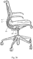
- Figures 1 a and 1b both show the seat 1 in a basic position I in which the seat 1 is upright, if it is unloaded or if an individual is sitting on the seat 1 and is not leaning or is only slightly leaning against the backrest part 5.
- the upper support 6a has a cross sectional area of 1 inch 2 (645.16 mm 2 ) and a moment of inertia of 0.005000 inch 4 (2080 mm 4 ) in the sections B and C.
- the cross sectional area can be from 0.3 inch 2 to 4 inch 2 (194.548 mm 2 to 2580.64 mm 2 ) and the moment of inertia can be from 0.000172 inch 4 to 0.011442 inch 4 (71.552 mm 4 to 4759.872 mm 4 ).
- the cross-sectional area is at least 0.3 inch 2 (194.548 mm 2 ) and the moment of inertia is at least 0.000172 inch 4 (194.548 mm 4 ).
- the seat element 2 tips or sways or rocks about a rocking point WP in a manner similar to the beam of a beam-balance, with the two supporting arms 6 of the seat element 2 being deformed in the process as a function of their particular position.
- the resting position II not only has an orientation of the guide element 9, which is designed as a lever 10, but also an orientation of the mechanical connecting link 12, which is designed as a lever 13, then changed.
- the supporting arm 6 is bent up, the upper support 6a thereof is forced to describe a relatively large radius. However, this is only possible if the upper support 6a with the pivotal point D121 for the lever 13 moves approximately in a direction m.
- the movement of the pivotal point D121 is predefined by the coupling of the upper support 6a to the lower support 6b by the mechanical connecting link 12 in order to prevent buckling or to obtain a defined movement.
- an individual sitting on the seat 1 is slightly raised in the region of his thighs as he leans back. This facilitates reaching the basic position I from the resting position II without energy having to be stored to a considerable extent in a spring element.
- the points of application of the weight of an individual sitting on the seat are therefore changed between the basic position I and the resting position II in order to obtain, as a function of the position of the seat element 2, a position which is oriented to an equilibrium.
- FIG 5 the illustrations of Figures 3 and 4 are shown superimposed.
- a front seat part 4a is raised at its pivotal point D91 by a height H1 in an arrow direction y and is pushed rearwards by a distance L1 in an arrow direction x.
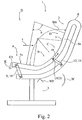
- Figure 6 illustrates, as an analogy with Figure 1a , a third variant of a seat 1 not falling within the scope of the claims with a seat element 2 in a basic position I.
- the description for Figures 1 a to 2 basically applies to this seat 1.
- the seat 1 of Figure 6 has an energy store or force store 15 which comprises a leaf spring 17 as the spring element 16.
- the leaf spring 17 is fastened in a lower support 6b of a first supporting arm 6 and stands in the way of a stop 18 belonging to the energy store 15.
- the stop 18 is fastened to an upper support 6a of the supporting arm 6.
- the stop 18 presses against the leaf spring 17.
- the energy store 15 damps the movement of the support 6a and assists a return movement into the basic position I.
- a contact body 19 of the stop 18 in an arrow direction y' by, for example, a displacement distance V1
- a resetting force produced by the energy store 15 can be adjusted.
- the embodiment of a corresponding energy store is provided on a left supporting arm of the seat 1, which supporting arm is not visible in the illustration of Figure 6 .
- the seat element 2 is fastened on a transverse support 14 of the underframe 3 by the lower supports 6b, 7b.
- the supporting elements 6, 7 or the lower supports 6b, 7b thereof are furthermore connected to each other via two transverse struts 20, 21 in order to couple the supporting elements 6 and 7 to each other so that the latter can mutually support each other if the seat 1 is loaded on one side.
- the underframe 3 also comprises a footplate 22 which is connected to the transverse support 14 via a strut 23.
- the seat 1 is in a basic position I.
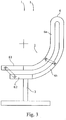
- FIG. 8 illustrates a fifth variant of a seat 1 not falling within the scope of the claims in a simplified side view.
- a seat element 2 is screwed here by lower supports 6b of two supporting arms 6 (only one supporting arm is visible in the side view) to a transverse support 14 of an underframe 3 at two fastening points 24, 25.
- the lower support 6b and an upper support 6a of the supporting arm 6 are connected in a region A of a front seat part 4a via a guide element 9.
- the guide element 9 is integrally formed as a single piece with the upper support 6a and the lower support 6b of the supporting arm 6.
- the guide element 9 rotates about a pivotal point or elastic region D92 from the basic position I in the clockwise direction in a direction of rotation w into the resting position II (compare Figures 9 and 11 ).
- the guide element 9, which is designed as a spoke 27, is situated in all possible positions between 9 o'clock and 12 o'clock between the basic position I and the resting position II.
- the guide element 9 raises the upper support 6a or the region A of the front seat part 4a at a pivotal point or elastic region D91.
- the guide element 9 merges into the upper support 6a.
- the region A is raised upwards by a distance H1 in an arrow direction y and is displaced to the right by a distance L1 in an arrow direction x (see Figure 12 ).
- This movement can be described by a type of rocking movement of the supporting arm 6 at a rocking point or rocking region WP.
- the rocking region here is arranged approximately wherever the lower support 6b of the supporting arm 6 leaves the transverse support 14 as a cantilever or wherever elastic deformation of the lower support 6b is possible.
- the supporting arm 6 is bent up in particular as a result of loading of a region D of an upper backrest part 5b.
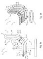
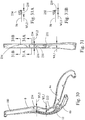
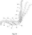
- FIG. 41 another seating arrangement not falling within the scope of the claims includes a back 5 having an upper most portion 60 formed from a single beam component free of any gap or spacing, a middle portion 62 angled relative to the upper portion and a lower portion 64 angled relative to the middle portion, with the bowed junction 66 between the lower and middle portion formed at substantially the lumbar region of the backrest.
- a pair of forward link members 72, 74 form a four-bar linkage.
- the middle portion is formed by spaced apart beams 68, 70 forming a gap therebetween that is free of any linking members as shown in Figure 42 .
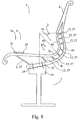
- FIG. 15 illustrates a perspective view of a seat element 2 of another variant of a seat 1 not falling within the scope of the claims.
- the seat element 2 has a supporting arm 6 which bears a covering 28 which forms a seat surface 29 and a backrest 30.
- the supporting arm 6 comprises a left, upper support 6a, a right, upper support 6a' and a lower support 6b located between them.
- the lower support 6b is connected to the left, upper support 6a by mechanical connecting links 12 and to the right, upper support 6a' by further mechanical connecting links 12.
- the upper supports 6a and 6a' are connected to each other by two transverse supports 31 and 32.
- the guide element 9 shown by dashed lines connects the underframe 3 and the upper support 6a.
- a seat part 4 of the seat 1 is situated with a rear seat part 4b in a region B, and a backrest part 5 is situated with a lower backrest part 5a in a region C.
- the upper supports 6a, 6a' are formed by central sections Q and Q'.
- the lower support 6b is formed in these two regions B and C by a central section R.
- All six connecting links 12 visible in Figure 16 are arranged between the central section Q of the upper support 6a and the central section R of the lower support 6b.
- a further six connecting links are arranged between the upper support 6a' and the lower support 6b (see Figure 17 ).
- Figure 17 illustrates, in a further perspective view, the seat element 2 shown in Figure 15 . It can be seen from this view that the seat element 2 or the supporting arm 6 is formed mirror-symmetrically with respect to a plane 41 situated vertically in space.
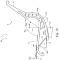
- Figures 21 to 25 illustrate side views of further variants of a seating arrangement 1 not falling within the scope of the claims, the seating arrangement 1 having a seat 4 which in respect of two carrying arms 6 or beams.
- the second carrying arm is completely concealed by the first carrying arm 6 in the side views of Figures 21-25 .
- the second carrying arm which is not visible, is of identical construction.
- an upper carrier 6a or beam member
- an upper carrier 6a is articulated on an upper part 108 of the substructure 3 such that it can be rotated in a first bearing 115, about an axis of rotation d115.
- a lower carrier 6b, or beam member, of the carrying arm 6 is articulated on the upper part 108 such that it can be rotated in a second bearing 116, about an axis of rotation d116.
- the upper carrier 6a and the lower carrier 6b are connected to one another via mechanical linking members 12, the lower carrier 6b being offset, or spaced apart, in relation to the upper carrier 6a so as to form a gap therebetween.
- the substructure 3 includes the upper part 108, a central part 109, a lower part 110 and a height-adjustable spring element 111 mounted between the upper part 108 and the central part 109.
- the lower part 110 may also be configured as a base part with castors.
- the upper carrier 6a of the carrying arm 6 is resiliently mounted on the upper part 108 of the substructure 3 via a spring element 114.
- the upper carrier 6a rests on the spring element 114 by way of its horizontal, first leg 6c.
- the additional support against a rotary movement of the carrying arm 6 about the axes of rotation d115 and d116 in a direction of rotation w can be modified by the properties of the spring element 114 and also by the positioning thereof. Dashed lines have been used to illustrate an alternative positioning of the spring element 114.
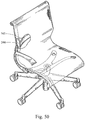
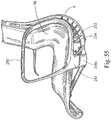
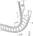
- linking members 612 are non-linear, for example being curved or bent forwardly at a lower connecting portion 622 thereof, and curved or bent rearwardly at an upper connecting portion 624 thereof (reversed "S" shape when viewed from the exterior side of the beam), such that a tangent line T through a middle of the link is not oriented perpendicular to the upper and lower carrier arms 606a, 606b, when the seating structure is in a neutral, upright position as shown in Figure 59 .
- at least the lower linking members beneath the seat and buttock portion are curved.
- the interior portions and linking members can be made of the same materials, or of various elastomeric materials, including without limitation, Hytrel, polyester elastomers, polypropylene elastomers, nylon elastomers, thermoplastic urethane elastomers or combinations thereof.
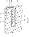
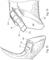
- a groove 620 facing laterally outwardly is formed in the upper carrier member 606a.
- the groove can be formed entirely in the material forming the forward portion of the upper carrier 606a as shown in Figures 56 and 57 , or between the material forming the upper portion 610 and the lower portion 616, which can help reduce high stress points in the beam.
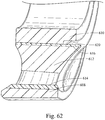
- the inner top portion of the groove, as shown in Figure 62 can also be curved to help reduce stresses at the corners of the groove 620.
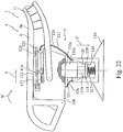
- Figure 22 shows a variant of the seating arrangement 1 not falling within the scope of the claims with a spring mechanism 416.
- the second carrying arm which is not visible in the side view, is assigned a spring mechanism of identical construction, which is completely concealed by the first spring mechanism 416.
- the substructure 3 of the seating arrangement 1 comprises an upper part 108, a central part 109 and a lower part 110.
- a height-adjustable spring element 111 is arranged between the upper part 108 and the central part 109.
- the upper part 108 also bears the spring mechanism 116.
- the height-adjustable spring element 111 comprises a pneumatic spring 111a and a spring element 117 arranged beneath a piston rod 111b of the pneumatic spring 111a.
- the piston rod 111b is guided in a pressure tube 111c.
- the upper part 108 is fastened on the pressure tube 111c, the pressure tube 111c being guided with sliding action in the vertical direction in the central part 109.
- the pneumatic spring 111a is supported on the spring element 117 by a flange plate 118 arranged on the piston rod 111b.
- the flange plate 118 and the spring element 117 form a weighing mechanism 119, which can establish the weight to which the seat 4 is subjected by an individual.
- the spring element 117 is arranged around the top of the piston rod 111b, with the pressure tube 111c supported by the base.
- the upper part 108 is secured to a housing 109, which is supported by the spring and piston rod via an adapter 150.
- the spring mechanism 116 is controlled via the weighing mechanism 119.
- a wire 120 of a Bowden cable 121 is fastened on the flange plate 118 of the weighing mechanism 119 and transmits the movement of the flange plate 118 to a bearing means 122, which is guided in a displaceable manner beneath a leaf spring 123.
- the spring mechanism 116 mentioned above comprises essentially the bearing means 122 and the leaf spring 123.
- the wire 120 of the Bowden cable 121 is guided in a hose 124, the hose being supported on the central part 108 and on the upper part 109.
- a vertical movement of the flange plate 118 in a direction y' causes the bearing means 122 to be drawn horizontally to the right in an arrow direction x by the Bowden cable 121.
- a level of prestressing of the leaf spring 123 is such that the bearing means 122 can move without any contact with the leaf spring 123 as long as an individual is only sitting on the seat in the upright position.
- the leaf spring 123 positions itself on the bearing means 122 for the first time when the individual leans back from their upright position, in a direction of rotation w, against a backrest 5.
- the spring mechanism 116 cushions the leaning-back movement of an individual in a weight-dependent manner.
- the seating arrangement 1 thus provides individuals of different weights with a high level of comfort without resilient deflection of the backrest having to be adjusted.
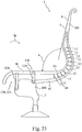
- FIG 23 illustrates another variant of the seating arrangement 1 not falling within the scope of the claims.
- An upper carrier 6a of the carrying arm 6 is articulated on an upper part 108 of the substructure 3 via two levers 128 and 129.
- This four-bar linkage 130 forms a coupling mechanism 131, which defines a tilting movement executed by the upper carrier 7a and/or a seat surface 170 when the seating arrangement 1 is subjected to loading by an individual sitting on it.
- a lower carrier 6b which is connected to the upper carrier 6a at a connecting location 180 and by a number of linking members 12, counteracts a lowering movement of the upper carrier 6a in the manner described.
- a lowering movement of legs 6c and 6f of the carriers 6a and 6b in a direction of rotation w also results in an increase in an opening angle ⁇ between the seat surface 170 and a backrest 5.
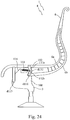
- Figure 24 illustrates a side view of another variant of a seating arrangement 1 not falling within the scope of the claims.
- An upper carrier 6a of the carrying arm 6 is articulated on an upper part 108 of the substructure 3 such that it can be rotated about an axis of rotation d115.
- a lower carrier 6b of the carrying arm 6 is articulated on the upper part 108 such that it can be rotated about an axis of rotation d116.
- the upper carrier 6a of the carrying arm 6 is articulated on the upper part 108 via a toggle 132, for rotation about the axis of rotation d116.
- Figure 25 shows a detail-specific view of the carrying arm 6 not falling within the scope of the claims.
- An upper reference point R7c is arranged on the horizontal, first leg 6c of the upper carrier 6a, and a lower reference point R7f is arranged on the horizontal, first leg 6f of the lower carrier 6b.
- the two reference points R7c, R7f are located on a vertical axis A7 in the non-loaded position A of the seating arrangement 1.
- the two reference points R7c, R7f move vertically downward in an arrow direction y' and move apart from one another in the horizontal direction.
- the imaginary reference point R7c moves over a circular path K7c about the axis of rotation d115 and the imaginary reference point R7f moves over a circular path K7f about the axis of rotation d116.
- the carriers 6a and 6b rotate in a direction of rotation w about their axes of rotation d115 and d116.
- the offset arrangement of the axes of rotation d115 and d116 means that this results in the horizontal legs 6c and 6f of the two carriers 6a and 6b being displaced in opposite directions.
- the upper carrier 6a is displaced in the direction of the backrest 5, and the lower carrier 6b is displaced in the direction of its bearing 116.
- the axis of rotation d116 is located above the axis of rotation d115, as seen in the vertical direction y, and the axes of rotation d115 and d116 are spaced apart from one another in the horizontal direction x.
- a spacing 135 provided between the axes of rotation d115 and d116 is larger than a spacing 136 between the axis of rotation d16 and the upper carrier 7a.
- a seating arrangement is shown similar to the variant shown in Figure 23 , but with a weighing mechanism as previously described.
- An upper carrier 6a of the carrying arm 6 is articulated on an upper part 108 of the substructure 3 via two levers 128 and 129.
- This four-bar linkage 130 forms a coupling mechanism 131, which defines a tilting movement executed by the upper carrier 6a and/or a seat surface 170 when the seating arrangement 1 is subjected to loading by an individual sitting on it.
- the lever 128 is substantially vertical, while the lever 129 also has a vertical vector component, with those levers absorbing the weight of the user as they initially sit in the seat prior to recline, which allows the weighing mechanism to function more efficiently.
- the levers 128, 129 further define the path of motion of the upper carrier 6a relative to the lower carrier.
- a lower carrier 6b which is connected to the upper carrier 6a at a connecting location 180 and by a number of linking members 12, counteracts a lowering movement of the upper carrier 6a in the manner described.
- a lowering movement of legs 6c and 6f of the carriers 6a and 6b in a direction of rotation w also results in an increase in an opening angle ⁇ between the seat surface 170 and a backrest 5.
- a pair of cross members 184, or spreaders or brace members, maintain a predetermined distance between the laterally spaced carrying arms or beams.
- the spreader 184 is connected to the upper arm 6a.
- a lever 529 is pivotally connected to the upper arm 6a and to an adapter 531 connected to the lower arm 6b so as to bear against the leaf spring.
- the stop member includes first and second arm portions 220, 222 extending diagonally from the linking member, such that the linking member and stop member are substantially X-shaped.
- the stop member arms 220, 222 are each configured with end portions 224, 226.
- the stop member 214 engages the carrier member 6a, 6b at a junction 228 or interior shoulder between the beam and the linking member.
- the term "coupled” as used herein means connected, whether directly or indirectly, for example by way of an intervening component, and includes integral formation of two or more components, or connection of separately formed components for example with various fasteners, including without limitation mechanical fasteners, adhesives, welding, stitching, tabs, snap-fits, etc.
- the upper and lower carrier members 6a, linking members 212 and stop members 214 are integrally formed. The stop members 214 prevent the beam from collapsing, for example when a user applies a load to the armrests of the chair when exiting the chair, or any other counterclockwise torsional load or downward vertical load when viewed from the left-hand side.
- the back 5 is provided with differential support, for example with more support in the lumbar region, without having to change the weave or materials of the membrane or alter the contour of the back.
- the upright portions 5 of the carriers 6 are bowed forwardly at the lumbar region so as to provide additional support for that region of the user's back.
- a pair of armrests 252 each includes a cantilevered arm support portion 254 extending forwardly, and an insert portion 256 extending laterally inwardly.
- the insert portion preferably has the same outer peripheral shape as the end portions 244 of the cross-member.
- the insert portion is received through an outwardly opening mouth 208 of the cavity.
- an inner wall 260 divides the cavity 248 into an inner and outer cavity or receptacles, with the insert portion 256 of the armrest abutting the outer surface of the wall 260 and the end portion 244 of the cross member abutting the inner surface of the wall.
- the wall can be omitted, with the insert portion abutting, receiving/surrounding, or being received in/surrounded by the end portion of the cross member.
- the insert portion 256 is releasably secured to the end portion 244.
- the insert portion is provided with an opening 262 and a catch 264, while the cross member is provided with a resilient tab member 266 having a hook portion 268.
- a surface 270 of the hook is provided with a tapered surface, which engages a surface of the opening 262 and biases the tab member 266 until the hook portion 268 is received in an opening 272 and engages the catch 264 with a snap-fit.
- the tab member 266 is inserted through an opening 261 in the wall 260. It should be understood that the tab member and catch can be reversed, with the tab member being formed on the insert portion and the catch formed on the end portion. It also should be understood that the arm can be releasably engaged with other devices, including cam locks, fasteners, adhesive, etc.
- the tab member is provided with an undercut 276 so as to allow it to be biased out of engagement with the catch.
- a surface of the tab spaced from the hook portion is configured as a release component 278, which can be engaged by the user to bias the tab out of engagement with the catch.
- a closed loop 280 forms an arm support portion, with a tubular support member 282 extending downwardly therefrom.
- a lower support includes an interfacing element 284 having an insert portion 286 received in the tubular portion.
- the armrest is modular and can interface with at least three different interface configurations 284a, b, c, including a right-hand interface, a left-hand interface and a center interface, used for example on a bench seating arrangement not falling within the scope of the claims shown for example in Figure 37 .
- a connector member 640 is pivotally connected at both ends thereof to the support member at axes 634, 636.
- the connector member is configured as an armrest having an upwardly extending portion 630 and a forwardly extending portion 632 joined at an intermediate portion 636, with the forwardly extending portion forming a rest surface for the arm of the user.
- the connector member or armrest stores energy and acts as a spring as the user reclines in the seating structure, such that carrier members 6a and 6b can be made thinner so as to reduce stresses therein.
- the portions 630, 632 are joined by a curved, living hinge portion 636, which can be thinner then the other portions to provide flexibility.
- the armrest can be made of glass filled polypropylene, nylon or other suitable materials.
- the linking members have been omitted from Figure 63 for the sake of simplicity, and it should be understood that the variant shown preferably includes linking members.
- a method not falling within the scope of the claims of assembling a load support structure, and in particular a seating arrangement includes providing a rectangular blank of stretchable, flexible membrane 56, or other fabric.
- the blank 288 has a side edges 290 that are parallel and are aligned with the beams, which are also parallel in an unloaded condition.
- the membrane is provided with a visible weave pattern, which includes longitudinally oriented lines 292 running parallel to the side edges of the blank, formed for example and without limitation by elastomeric monofilaments.
- the membrane can be made from various materials described in U.S. Patent No. 6,059,368 , and U.S.
- Patent Application 09/666,624 entitled Carrier and Attachment Method for Load Bearing Fabric, filed September 20, 2000.
- the membrane 56 is connected to the laterally spaced beams 6, for example as shown in Figures 46-48 , which show variants not falling within the scope of the claims, so as to define a body support surface, which can support the user directly (e.g., when exposed) or indirectly (e.g., when covered with an additional layer (e.g., foam, fabric, etc.)).
- the side edges 290 are folded over and overmolded with a carrier member 294, with the edge portion then being inserted into a cavity or recess 296, 620 opening laterally outwardly, as also shown in FIGS.
- the carrier further includes a bumper portion 298 bearing against a side of the beam, so as to reduce wear and tear on the membrane and provide additional flex.
- An upper side edge or surface 300 of the beam is offset inwardly from a lower side edge or surface 302 of the beam so as to accommodate the thickness of the carrier and membrane, which lies substantially flush with the lower side surface 302.
- the carrier 294 is preferably made of HYTREL material.
- An overlay material 304 can also be secured over the membrane.
- the overlay can be easily removed for cleaning or replacement, for example to quickly alter the aesthetics of the chair.
- the overlay such as a fabric or other three-dimensional material, includes a plug 306 that is configured to be received in an opening 308 formed in an end portion of the beam, configured in one variant as a hook portion or C-shaped scroll. A similar connection is made to front edge of the carrier arms defining the seat.
- the membrane blank 288 can further be provided with differential stiffnesses by changes in the weave and materials.
- the flexibility or stiffness can be varied by varying the flexural modulus of monofilaments or yarns, by varying the quantity of the monofilaments and/or yarns per inch, and/or by varying the weave pattern of the monafilaments and/or yarns.
- the blank is provided with regions 310, 312, 314 exhibiting three different stiffness properties, with the second stiffness being about 1.5 times the stiffness of the first and the third being about 2.0 times the stiffness of the first Stiffness is measured and defined by an Indentation Force Deflection test, wherein a predetermined deflection is applied, with the amount of force measured as required to achieve the predetermined deflection. The greater the load required to achieve a predetermined deflection, the greater the stiffness.
- Figure 49 which shows a variant not falling within the scope of the claims, the front regions 314 of the seat and the spinal region of the back are made the most stiff, with the lumbar and uppermost regions 312 of the back being made the next stiffest.
- the lower, outboard regions 310 of the back, the thoracic regions of the back and the rear, buttock supporting portion of the seat are made the least stiff.
- the overall length is 1045.3mm, with a length between the top edge 734 and the intermediate transition location 736 of 679.4mm
- the top edge has a 2.5% stretch, while the intermediate region has a 5% stretch, and the side edges 738 having no stretch.
- Stretch is defined in terms of strain, i.e. (change in length)/(original length), or elongation.
- the top of the suspension membrane is 15 inches (381 mm) across and the bottom is 20 inches (508 mm) across, and the beams are moved apart 1 inch (25.4 mm) during assembly, the bottom stretch would be 5% (1 inch/20 inches (25.4 mm/508 mm)) and the top stretch would be 6.7% (1 inch/15 inches (25.4 mm/381 mm).
- the distance between the tops of the beams are closer than the distance between the lower portions of the beams, such that the stretch of the back portion of the suspension membrane is less than the stretch of the seat portion of the suspension membrane. If the membrane "blank" were rectangular, then it is possible that a negative stretch (saggy fabric) would be imparted to the backrest portion of the suspension material when the seat is stretched a desired amount.
- the carrier 290 not falling within the scope of the claims with the in-molded suspension material is inserted into the groove 296, 620 formed in the spaced apart beams (fabric omitted from Figure 65 for the purposes of clarity).
- four clips 700 configured in one variant as spring steel clips, are secured to the fabric or membrane material, for example with one or more hooks or barbs, along with sliding the clip 700 (U-shaped) over the carrier 290 and fabric as shown in Figure 65 (fabric omitted for clarity).
- the carrier 290 and membrane are pressed into the groove 620, and the clips 700, preferably steel, are then inserted into openings 704 facing laterally outwardly at the four corners 710 of the beam as shown in Figures 64-66 .
- a laterally extending opening 704 is formed in the ends of each beam.
- a cantilevered catch portion 702 is depressed by the walls of the opening until it reaches the other side, where the spring force releases the catch portion 702, which engages the inner side surface 714 of the beam.
- the catch portion 702, or tab can be pressed inwardly such that the attachment clip can be slid back out of the opening and thereby release the membrane.
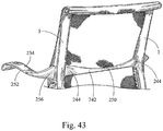
- the top 734 of the membrane is wrapped around one or more laterally extending cross member 750 and is secured to a fastener plate 752 disposed inside the cross member, for example with snaps or Christmas tree fasteners.
- the cross member 750 can be formed from two separate and spaced apart members joined with the fastener plate 752 that form a gap therebetween adjacent the middle of the top edge of the backrest.
- the membrane 730 can be secured to the cross member with conventional screws or adhesives, or combinations of the various fasteners.
- an edge portion of the fabric is secured in a groove of the cross member, or is trapped between the cross member and fastener plate.
- the cross member 750 is formed as a half or partial tubular structure, and is preferably a flexible material such as TPE.
- the fastener plate 752 is relatively rigid, such as a hard plastic such as polyester.
- the cross member 750 has end portions 754 configured and shaped (e.g., non-circular or oblong or "T" shaped) to prevent the cross member 750 from rotating relative to the beams 6.
- the cross member 750 allows the fabric 730 to maintain a curved appearance across the top edge of the backrest, while also allowing the membrane or fabric to be pulled tight toward the middle of the back to prevent a wrinkled appearance.
- the shape and material of the cross member 750 ensure that it does not interfere with the comfort of the user.
- the cross member also provides a handle or grippable portion for a user to move the chair about when not seated therein.
- FIG. 32-35 another variant of a seating arrangement not falling within the scope of the claims includes a pair of carriers 406, or support members, each defining an upright 405 and a forwardly extending seat support 404.
- the support members 406 are spaced apart in the lateral direction, and each include first and second spaced apart beam members 406a, b forming a gap 411 therebetween as described above.
- At least one and preferably a plurality (meaning more than one) linking member 412 bridges the gap and connects the beam members.
- the second beam members 406b shown in this variant as the lower beam member, are coupled with a cross member 414.
- the cross-member 414 is integrally formed with the second beam members 406b, although it can be formed as a separate member.
- the cross member 414 is fixedly connected to a base at a middle portion thereof, such that the cross member does not rotate about a horizontal axis.
- the lower/forward portions of the second beams members 406b at the seat/back junction and/or under the seat, or portions thereof, extend inwardly toward a centerline relative to the beam members 406a spaced thereabove. In this way, the lower beam members diverge inwardly relative to the upper beam members, although portions of the upper and lower beam members 406a,b remain in a vertical plane in one variant.
- the cross member 414 can be connected to a base that is supported on a support column that rotates about a vertical axis.
- the base can be configured as a sled base 416, including in one variant a pair of triangular shaped legs angled inwardly and joined at a middle portion which is then connected to the cross member 414.
- the legs can take a number of other shapes not shown, including a C-shaped sled base leg.
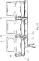
- the middle portion not falling within the scope of the claims can be connected to a beam 418, with a plurality of seating arrangements connected to the beam.
- Such a configuration can be used for stadium seating, movie theaters, class-rooms, waiting rooms, jury boxes, or any other setting requiring multiple, sequential seating.
- the beam can be linear or curvilinear, for example configured with a serpentine shape.
- a front link 420 not falling within the scope of the claims, also functioning as a spreader or brace member, is pivotally connected to the seat supports 404 about a horizontal axis 422.
- the front link 420 is substantially U-shaped.
- a middle portion 426 of the link 420 is pivotally connected to a lug 428 of the middle portion 414 of the cross member.
- a pair of rear link members 430 further pivotally connect the seat support to the bottom beam, or cross member.
- the rear link members have opposite end portions pivotally connected about pivot axes 424, 432.
Landscapes
- Health & Medical Sciences (AREA)
- Dentistry (AREA)
- General Health & Medical Sciences (AREA)
- Engineering & Computer Science (AREA)
- Mechanical Engineering (AREA)
- Chairs Characterized By Structure (AREA)
- Chair Legs, Seat Parts, And Backrests (AREA)
- Body Structure For Vehicles (AREA)
- Seats For Vehicles (AREA)
Priority Applications (1)
| Application Number | Priority Date | Filing Date | Title |
|---|---|---|---|
| EP15165002.5A EP2937019B1 (en) | 2007-09-20 | 2008-09-18 | Load support structure |
Applications Claiming Priority (2)
| Application Number | Priority Date | Filing Date | Title |
|---|---|---|---|
| US99473707P | 2007-09-20 | 2007-09-20 | |
| EP08832398.5A EP2200480B1 (en) | 2007-09-20 | 2008-09-18 | Seating structure |
Related Parent Applications (2)
| Application Number | Title | Priority Date | Filing Date |
|---|---|---|---|
| EP08832398.5A Division-Into EP2200480B1 (en) | 2007-09-20 | 2008-09-18 | Seating structure |
| EP08832398.5A Division EP2200480B1 (en) | 2007-09-20 | 2008-09-18 | Seating structure |
Related Child Applications (2)
| Application Number | Title | Priority Date | Filing Date |
|---|---|---|---|
| EP15165002.5A Division EP2937019B1 (en) | 2007-09-20 | 2008-09-18 | Load support structure |
| EP15165002.5A Division-Into EP2937019B1 (en) | 2007-09-20 | 2008-09-18 | Load support structure |
Publications (2)
| Publication Number | Publication Date |
|---|---|
| EP2798977A1 EP2798977A1 (en) | 2014-11-05 |
| EP2798977B1 true EP2798977B1 (en) | 2017-11-08 |
Family
ID=40468756
Family Applications (4)
| Application Number | Title | Priority Date | Filing Date |
|---|---|---|---|
| EP14170499.9A Active EP2798977B1 (en) | 2007-09-20 | 2008-09-18 | Load support structure |
| EP15165002.5A Active EP2937019B1 (en) | 2007-09-20 | 2008-09-18 | Load support structure |
| EP13190377.5A Active EP2689693B1 (en) | 2007-09-20 | 2008-09-18 | Load support structure |
| EP08832398.5A Active EP2200480B1 (en) | 2007-09-20 | 2008-09-18 | Seating structure |
Family Applications After (3)
| Application Number | Title | Priority Date | Filing Date |
|---|---|---|---|
| EP15165002.5A Active EP2937019B1 (en) | 2007-09-20 | 2008-09-18 | Load support structure |
| EP13190377.5A Active EP2689693B1 (en) | 2007-09-20 | 2008-09-18 | Load support structure |
| EP08832398.5A Active EP2200480B1 (en) | 2007-09-20 | 2008-09-18 | Seating structure |
Country Status (8)
| Country | Link |
|---|---|
| US (8) | US7926879B2 (https=) |
| EP (4) | EP2798977B1 (https=) |
| JP (1) | JP5391201B2 (https=) |
| CN (2) | CN101868168B (https=) |
| BR (1) | BRPI0817119B8 (https=) |
| CA (1) | CA2699914C (https=) |
| MX (1) | MX2010003141A (https=) |
| WO (1) | WO2009039231A2 (https=) |
Families Citing this family (99)
| Publication number | Priority date | Publication date | Assignee | Title |
|---|---|---|---|---|
| US7992936B2 (en) | 2006-03-24 | 2011-08-09 | Herman Miller, Inc. | Seat |
| CA2645964C (en) | 2006-03-24 | 2014-05-06 | Herman Miller, Inc. | Seating arrangement |
| JP5391201B2 (ja) | 2007-09-20 | 2014-01-15 | ハーマン、ミラー、インコーポレイテッド | 荷重支持構造 |
| DE102009017591A1 (de) | 2009-04-19 | 2010-10-21 | Rudolf Dr. Bannasch | Manipulatorwerkzeug und Halt- und/oder Spreizwerkzeug mit wengistens einem Manipulatorwerkzeug |
| US8156995B2 (en) | 2009-04-20 | 2012-04-17 | Rite-Hite Holding Corporation | Door element |
| USD660023S1 (en) * | 2009-05-26 | 2012-05-22 | Cornell University | Chair |
| CN102781281B (zh) * | 2010-02-26 | 2016-05-11 | 多纳蒂股份公司 | 用于同步椅子的椅座和椅背的装置 |
| EP2407059B1 (en) * | 2010-07-15 | 2013-01-02 | Pro-Cord S.p.A. | A chair with tilting backrest |
| DE102011100708B4 (de) | 2011-05-06 | 2013-07-11 | Haworth, Inc. | Sitzmöbel, insbesondere Bürostuhl |
| DE102011104972B4 (de) * | 2011-06-08 | 2015-03-05 | Haworth, Inc. | Sitzmöbel, insbesondere Bürostuhl |
| US8567864B2 (en) | 2011-08-12 | 2013-10-29 | Hni Corporation | Flexible back support member with integrated recline stop notches |
| MX344266B (es) | 2011-12-08 | 2016-12-09 | Miller Herman Inc | Miembro de soporte de cuerpo compuesto y métodos para la manufactura y reciclamiento del mismo. |
| DE102012013208B4 (de) | 2012-05-07 | 2019-07-25 | Adient Luxembourg Holding S.À R.L. | Sitzteil eines Fahrzeugsitzes |
| IN2014DN08535A (https=) | 2012-05-07 | 2015-05-15 | Johnson Controls Tech Co | |
| USD707995S1 (en) | 2012-05-23 | 2014-07-01 | Hni Technologies Inc. | Chair |
| US9198514B2 (en) | 2012-05-23 | 2015-12-01 | Hni Technologies Inc. | Chair with pivot function and method of making |
| DE102012208721A1 (de) * | 2012-05-24 | 2013-11-28 | Lufthansa Technik Ag | Flugzeugsitz mit einer Sitzbaugruppe |
| US9161630B2 (en) * | 2012-05-25 | 2015-10-20 | Faurecia Automotive Seating, Llc | Deformable seat shell with motion control |
| US8820835B2 (en) | 2012-08-29 | 2014-09-02 | Hni Technologies Inc. | Resilient chair incorporating multiple flex zones |
| USD707477S1 (en) | 2012-08-29 | 2014-06-24 | Hni Technologies, Inc. | Chair |
| CA2881683C (en) | 2012-09-17 | 2018-07-24 | Steelcase Inc. | Floor-to-ceiling partition wall assembly |
| US11304528B2 (en) | 2012-09-20 | 2022-04-19 | Steelcase Inc. | Chair assembly with upholstery covering |
| US8998339B2 (en) | 2012-09-20 | 2015-04-07 | Steelcase Inc. | Chair assembly with upholstery covering |
| US11229294B2 (en) | 2012-09-20 | 2022-01-25 | Steelcase Inc. | Chair assembly with upholstery covering |
| US10105886B2 (en) | 2012-10-09 | 2018-10-23 | Reliant Worldwide Plastics, Llc | Thermoplastic injection molded element with integral thermoplastic positioning system for reinforced composite structures |
| MY183045A (en) | 2013-03-15 | 2021-02-08 | Haworth Inc | Office chair |
| DE102013005861A1 (de) * | 2013-04-08 | 2014-10-09 | Burkhard Schmitz | Mechanikbaugruppe für einen Stuhl und Stuhl mit einer derartigen Mechanikbaugruppe |
| USD703457S1 (en) | 2013-06-07 | 2014-04-29 | Herman Miller, Inc. | Chair |
| US9162832B2 (en) | 2013-07-02 | 2015-10-20 | Rite-Hite Holding Corporation | Vehicle-actuated weather barrier apparatus |
| WO2015003796A1 (de) * | 2013-07-07 | 2015-01-15 | Bock 1 Gmbh & Co. Kg | Mechanik für einen bürostuhl |
| WO2015038630A1 (en) | 2013-09-10 | 2015-03-19 | Reliant Worldwide Plastics, Llc | Tray table and method of manufacture |
| MA39944A (fr) | 2014-05-02 | 2017-03-08 | Reliant Worldwide Plastics Llc | Procédé et système pour ensemble de dossier de siège thermoplastique homogène |
| EP3154825A4 (en) * | 2014-06-16 | 2018-04-25 | Reliant Worldwide Plastics, LLC | Method and apparatus for composite thermoplastic arm rest assembly |
| KR102250238B1 (ko) * | 2014-08-18 | 2021-05-10 | 삼성전자주식회사 | 고정 모듈 및 이를 포함하는 운동 보조 장치 |
| GB2530297B (en) * | 2014-09-18 | 2019-06-05 | Perch Dynamic Solutions Ltd | A chair back |
| US9883746B2 (en) | 2014-11-11 | 2018-02-06 | Pro-Cord S.P.A. | Chair with seat and backrest movable in a synchronized way |
| BR112017014533A2 (pt) | 2015-01-16 | 2018-01-16 | Miller Herman Inc | estrutura de assento de suspensão zoneadas |
| CN104665316B (zh) * | 2015-03-27 | 2017-12-05 | 宋为民 | 一种椅子 |
| USD808187S1 (en) | 2016-04-12 | 2018-01-23 | Steelcase Inc. | Seating shell |
| USD802951S1 (en) | 2016-04-12 | 2017-11-21 | Steelcase Inc. | Chair |
| USD804209S1 (en) | 2016-04-12 | 2017-12-05 | Steelcase Inc. | Chair |
| US10182656B2 (en) | 2015-04-13 | 2019-01-22 | Steelcase Inc. | Seating components with laminated bonding material |
| US10966527B2 (en) * | 2017-06-09 | 2021-04-06 | Steelcase Inc. | Seating arrangement and method of construction |
| US10021984B2 (en) | 2015-04-13 | 2018-07-17 | Steelcase Inc. | Seating arrangement |
| US11259637B2 (en) | 2015-04-13 | 2022-03-01 | Steelcase Inc. | Seating arrangement |
| USD804876S1 (en) | 2016-04-12 | 2017-12-12 | Steelcase Inc. | Chair |
| USD804840S1 (en) | 2016-04-12 | 2017-12-12 | Steelcase Inc. | Chair |
| USD804839S1 (en) | 2016-04-12 | 2017-12-12 | Steelcase Inc. | Chair |
| US10194750B2 (en) | 2015-04-13 | 2019-02-05 | Steelcase Inc. | Seating arrangement |
| USD821793S1 (en) | 2016-04-12 | 2018-07-03 | Steelcase Inc. | Seating shell |
| USD804841S1 (en) | 2016-04-12 | 2017-12-12 | Steelcase Inc. | Chair |
| USD804875S1 (en) | 2016-04-12 | 2017-12-12 | Steelcase Inc. | Chair |
| AU2016287487B2 (en) * | 2015-06-29 | 2020-11-26 | MillerKnoll, Inc | Attachment structure for suspension seating |
| WO2017070186A1 (en) | 2015-10-23 | 2017-04-27 | Reliant Worldwide Plastics, Llc | Method and apparatus for a homogeneous thermoplastic leg support |
| US10766174B2 (en) | 2015-11-04 | 2020-09-08 | Reliant Worldwide Plastics, Llc | Method and apparatus for a thermoplastic homogeneous failure module |
| US10278495B2 (en) | 2016-02-11 | 2019-05-07 | Get Back, Inc. | Swing stool table kit |
| USD779253S1 (en) | 2016-02-12 | 2017-02-21 | Haworth, Inc. | Back support for a chair |
| USD779254S1 (en) | 2016-02-12 | 2017-02-21 | Haworth, Inc. | Armrests for a chair |
| USD793787S1 (en) | 2016-02-12 | 2017-08-08 | Haworth, Inc. | Portion of a back support for a chair |
| USD779251S1 (en) | 2016-02-12 | 2017-02-21 | Haworth, Inc. | Lumbar support for a chair |
| USD782859S1 (en) | 2016-02-12 | 2017-04-04 | Haworth, Inc. | Back support for a chair |
| USD782241S1 (en) | 2016-02-12 | 2017-03-28 | Haworth, Inc. | Back support for a chair |
| USD779255S1 (en) | 2016-02-12 | 2017-02-21 | Haworth, Inc. | Headrest for a chair |
| USD784749S1 (en) | 2016-02-12 | 2017-04-25 | Haworth, Inc. | Lumbar support for a chair |
| USD779250S1 (en) | 2016-02-12 | 2017-02-21 | Haworth, Inc. | Portion of a back support for a chair |
| USD779248S1 (en) | 2016-02-12 | 2017-02-21 | Haworth, Inc. | Armrests for a chair |
| US10182657B2 (en) | 2016-02-12 | 2019-01-22 | Haworth, Inc. | Back support for a chair |
| USD779252S1 (en) | 2016-02-12 | 2017-02-21 | Haworth, Inc. | Back support for a chair |
| USD932203S1 (en) | 2016-04-12 | 2021-10-05 | Steelcase Inc. | Seating arrangement |
| US10463153B2 (en) | 2016-06-09 | 2019-11-05 | Steelcase Inc. | Seating arrangement |
| CN109788851B (zh) | 2016-09-29 | 2022-05-27 | 斯迪尔科斯公司 | 柔顺的座椅结构 |
| DE102017001503A1 (de) | 2017-02-16 | 2018-08-16 | Oliver Deichmann | Ein Stuhl, inbesondere ein Bürostuhl, mit einer zwischen der Sitzfläche und der Rückenlehne wirkenden Mechanik, durch die der Neigungswiderstand der Rückenlehne in Abhängigkeit von der Belastung der Sitzfläche steht. Die Sitzfläche wird in Abhängigkeit von der Belastung der Rückenlehne wenigstens teilweise angehoben. |
| DE202017007682U1 (de) | 2017-02-16 | 2024-04-19 | Oliver Deichmann | Stuhl |
| US10194749B1 (en) | 2017-05-23 | 2019-02-05 | Yeti Coolers, Llc | Portable chair and methods of forming a portable chair |
| US10743670B2 (en) | 2017-05-23 | 2020-08-18 | Yeti Coolers, Llc | Portable chair and cup holder assembly |
| US10561249B2 (en) | 2017-05-23 | 2020-02-18 | Yeti Coolers, Llc | Portable chair and cup holder assembly |
| EP3409637B1 (en) * | 2017-05-31 | 2020-04-15 | Toyota Material Handling Manufacturing Sweden AB | A lift-truck comprising a movable foot guard |
| US10799028B2 (en) | 2017-08-10 | 2020-10-13 | NHI Corporation | Chairs including flexible frames |
| DK3691497T3 (da) * | 2017-10-05 | 2024-07-15 | Godrej & Boyce Mfg Co Ltd | Stillingsadaptiv arbejdsstol |
| US11291305B2 (en) | 2017-12-05 | 2022-04-05 | Steelcase Inc. | Compliant backrest |
| US10813463B2 (en) | 2017-12-05 | 2020-10-27 | Steelcase Inc. | Compliant backrest |
| USD843152S1 (en) | 2018-01-10 | 2019-03-19 | Yeti Coolers, Llc | Portable chair |
| USD843151S1 (en) | 2018-01-10 | 2019-03-19 | Yeti Coolers, Llc | Portable chair |
| USD850810S1 (en) | 2018-01-10 | 2019-06-11 | Yeti Coolers, Llc | Portable chair |
| USD843150S1 (en) | 2018-01-10 | 2019-03-19 | Yeti Coolers, Llc | Portable chair |
| US10625647B1 (en) * | 2018-10-04 | 2020-04-21 | The Boeing Company | Seatback support structures with variable and adjustable stiffness |
| ES3035683T3 (en) | 2019-02-21 | 2025-09-08 | Steelcase Inc | Body support member |
| WO2020201384A1 (de) | 2019-04-01 | 2020-10-08 | Adient Engineering and IP GmbH | Strukturbauteil, sitzkomponente und fahrzeugsitz |
| CN113748050B (zh) * | 2019-04-01 | 2024-07-26 | 安道拓美国有限责任公司 | 柔性结构部件以及用途 |
| US11969094B2 (en) * | 2019-06-11 | 2024-04-30 | MillerKnoll, Inc. | Chair |
| WO2021055441A1 (en) | 2019-09-18 | 2021-03-25 | Steelcase Inc. | Body support member with lattice structure |
| US11357329B2 (en) | 2019-12-13 | 2022-06-14 | Steelcase Inc. | Body support assembly and methods for the use and assembly thereof |
| US11617444B2 (en) | 2020-03-02 | 2023-04-04 | Steelcase Inc. | Body support assembly and methods for the use and assembly thereof |
| US11602225B2 (en) * | 2020-06-25 | 2023-03-14 | Haworth, Inc. | Knit seat back for an office chair |
| US11812870B2 (en) | 2021-02-10 | 2023-11-14 | Steelcase Inc. | Body support structure |
| WO2022178129A1 (en) * | 2021-02-17 | 2022-08-25 | Hni Technologies Inc. | Chair with dynamic motion features |
| EP4674318A3 (en) | 2021-03-17 | 2026-04-01 | Steelcase Inc. | Seating arrangement |
| JP7794603B2 (ja) * | 2021-09-24 | 2026-01-06 | 株式会社オカムラ | 椅子の荷重支持構造体及び椅子 |
| US20240225292A1 (en) * | 2023-01-11 | 2024-07-11 | Illinois Tool Works Inc. | Apparatus and method for manufacturing a support frame for a seat assembly |
Family Cites Families (208)
| Publication number | Priority date | Publication date | Assignee | Title |
|---|---|---|---|---|
| US488095A (en) * | 1892-12-13 | Knockdown folding chair | ||
| US693197A (en) * | 1901-11-20 | 1902-02-11 | Charles B White | Knockdown chair. |
| US946225A (en) * | 1909-03-15 | 1910-01-11 | Paul Irwin J | Seat. |
| US2771122A (en) | 1953-08-28 | 1956-11-20 | Straub Carl | Removable cover lawn chair |
| US3041109A (en) * | 1958-09-29 | 1962-06-26 | Miller Herman Inc | Web and spreader furniture construction |
| NL122034C (https=) | 1959-12-12 | |||
| CA721090A (en) * | 1961-06-05 | 1965-11-09 | L. Propst Robert | Net seating |
| US3230011A (en) * | 1963-07-05 | 1966-01-18 | Miller Herman Inc | Seating |
| US3208794A (en) * | 1964-08-31 | 1965-09-28 | Air Lab Service Co Inc | Cover for aircraft seat |
| US3300251A (en) * | 1965-06-10 | 1967-01-24 | Knoll Associates | Upholstery cover-frame connection |
| US3565482A (en) * | 1968-06-24 | 1971-02-23 | Leif Blodee | Adjustable contour chair |
| US3586370A (en) * | 1968-12-04 | 1971-06-22 | American Seating Co | Upholstered chair |
| US3640576A (en) * | 1970-06-08 | 1972-02-08 | Art Metal Knoll Corp | Furniture construction |
| US3669496A (en) * | 1970-12-03 | 1972-06-13 | American Desk Mfg Co | Chair and seat and back unit therefor |
| SE372878B (https=) * | 1972-03-14 | 1975-01-20 | K Borggren | |
| DE2238675A1 (de) * | 1972-08-05 | 1974-02-14 | Porsche Ag | Ruhemoebel |
| US3914103A (en) | 1974-09-23 | 1975-10-21 | Formex Mfg Inc | Abstract having product ejection means for forming plastic |
| GB1487497A (en) * | 1975-04-10 | 1977-09-28 | Otaco Ltd | Transportation seating construction and system |
| US4062590A (en) * | 1976-05-24 | 1977-12-13 | Fixtures Manufacturing Corporation | Chair structure |
| US4161315A (en) | 1977-11-14 | 1979-07-17 | Walton Jimmy W | Stacker for game counters |
| US4230365A (en) * | 1979-01-18 | 1980-10-28 | Alexander Messinger | Article of furniture and method of manufacture |
| AU6563380A (en) | 1979-12-19 | 1983-01-06 | Mckinlay, I.B. | Foils operating in fluid medium |
| DE3036993A1 (de) | 1980-10-01 | 1982-05-13 | Wilkhahn Wilkening + Hahne GmbH + Co, 3252 Bad Münder | Arbeits-sitzmoebel |
| DE8135614U1 (de) * | 1981-12-07 | 1983-11-10 | Gebr. Thonet GmbH, 6000 Frankfurt | Sitzmoebel |
| US4529247A (en) * | 1982-04-15 | 1985-07-16 | Herman Miller, Inc. | One-piece shell chair |
| US4522444A (en) * | 1982-09-15 | 1985-06-11 | Charles Pollock | Stacking chair |
| EP0107627B1 (en) * | 1982-10-22 | 1986-01-02 | Castelli S.P.A. | Chair having a back comprising a plurality of articulated segments |
| US5240308A (en) * | 1983-11-09 | 1993-08-31 | Goldstein Glenn A | Ergonomic adjustable chair and method |
| US4601516A (en) * | 1984-03-16 | 1986-07-22 | Klein Gerhart P | Contoured chair |
| US4592126A (en) * | 1984-12-14 | 1986-06-03 | Homecrest Industries Incorporated | Method for constructing furniture having a flexible sheet portion |
| US5050931A (en) * | 1986-04-10 | 1991-09-24 | Steelcase Inc. | Controlled deflection front lip for seating |
| US4647290A (en) | 1986-06-13 | 1987-03-03 | Betz Laboratories, Inc. | Process and composition for color stabilized distillate fuel oils |
| JPS63111815A (ja) * | 1986-10-30 | 1988-05-17 | コクヨ株式会社 | 椅子 |
| FR2620791B1 (fr) * | 1987-09-22 | 1989-12-29 | Strafor Sa | Structure deformable |
| US4889385A (en) | 1988-03-09 | 1989-12-26 | American Seating Company | Chair seat-and-back support |
| JP2592108B2 (ja) * | 1988-08-31 | 1997-03-19 | コクヨ株式会社 | 背もたれ付椅子 |
| DE3841532A1 (de) * | 1988-12-09 | 1990-06-13 | Bayer Ag | Rueckenlehnen-tragstruktur fuer einen fahrzeugsitz und fahrzeugsitz-rueckenlehne mit dieser rueckenlehnen-tragstruktur |
| US5114210A (en) * | 1989-01-11 | 1992-05-19 | Maxton Fox Commercial Furniture Pty. Ltd. | Tilting chair with improved lumbar support |
| USD320034S (en) * | 1989-02-08 | 1991-09-17 | Ultimate Support Systems, Inc. | Keyboard stand |
| JPH0823095B2 (ja) | 1989-06-06 | 1996-03-06 | 東レ株式会社 | 補強繊維織物 |
| EP0403450A1 (en) * | 1989-06-12 | 1990-12-19 | The Shaw-Walker Company | Ergonomic seat and back structure for a chair |
| JPH0773555B2 (ja) * | 1989-07-31 | 1995-08-09 | 株式会社イトーキクレビオ | 椅子における座席体の弾力調節装置 |
| DE4031496C1 (en) * | 1990-10-05 | 1991-10-24 | Dreipunkt Gmbh Objekt- Und Wohnmoebel, 7322 Donzdorf, De | Chair with central column and seat frame - has arm rests, whose end facing seat are coupled to ends of leaf spring on edge |
| US5318346A (en) | 1991-05-30 | 1994-06-07 | Steelcase Inc. | Chair with zero front rise control |
| JP2919131B2 (ja) | 1991-10-22 | 1999-07-12 | 株式会社イトーキクレビオ | 椅子の傾動制御装置 |
| JPH05137857A (ja) * | 1991-11-08 | 1993-06-01 | Tokyo Interior:Kk | 敷布団用硬わた |
| US5320410A (en) * | 1992-01-14 | 1994-06-14 | Steelcase Inc. | Chair control |
| KR100334316B1 (ko) | 1992-06-15 | 2002-10-11 | 헤르만밀러인코퍼레이티드 | 사무용의자의지지장치및제조방법 |
| US5328245A (en) * | 1992-10-30 | 1994-07-12 | Thomas J. Marks | Chair having adjustable back support |
| US5518294A (en) * | 1993-04-05 | 1996-05-21 | Ligon Brothers Manufacturing Company | Variable apex back support |
| USD355924S (en) * | 1993-06-18 | 1995-02-28 | Hal Leonard Publishing Corporation | Electronic keyboard |
| USD354384S (en) * | 1993-11-02 | 1995-01-10 | Cari-All Inc. | Shopping cart rear gate |
| FR2715124B1 (fr) | 1993-12-01 | 1998-02-27 | Arnaud Ballu | Gréement pour bateau à voile. |
| DE4410383C2 (de) * | 1994-03-25 | 1996-07-25 | Desanta | Stuhl |
| FR2719587B1 (fr) | 1994-05-03 | 1996-07-12 | Roussel Uclaf | Nouveaux dérivés de l'érythromycine, leur procédé de préparation et leur application comme médicaments. |
| US5810438A (en) | 1994-06-13 | 1998-09-22 | Herman Miller, Inc. | One piece molded seating structure |
| CN2199888Y (zh) * | 1994-08-11 | 1995-06-07 | 赖福财 | 汽车椅垫 |
| LU88528A1 (fr) | 1994-09-01 | 1996-03-18 | Laurent Thirkell | Structure hydrodynamique à profil variable |
| DE4433663A1 (de) | 1994-09-21 | 1996-03-28 | Gotthard Bresch | Stuhl |
| USD377431S (en) * | 1994-09-29 | 1997-01-21 | Herman Miller, Inc. | Seat and back unit for a chair |
| JP3011632U (ja) * | 1994-11-28 | 1995-05-30 | 喜代四 星野 | 腰掛け専用ベンチ |
| GB9500022D0 (en) * | 1995-01-04 | 1995-03-01 | Unwalla Jamshed | Integrated seat and back and mechanism for chairs |
| US5661835A (en) * | 1995-01-19 | 1997-08-26 | Sumitomo Electric Industries, Ltd. | Optical composite module and method of assembling the same |
| US5649743A (en) * | 1995-01-31 | 1997-07-22 | Victor Stanley, Inc. | Vandal-resistant bench and frame therefor |
| DE29505064U1 (de) * | 1995-03-25 | 1996-07-25 | Heerklotz, Siegfried, Dipl.-Ing., 49143 Bissendorf | Flächiger Polsterkörper |
| US6702391B1 (en) * | 1995-06-07 | 2004-03-09 | Grant Stipek | Furniture with molded frame |
| USD390026S (en) * | 1996-04-18 | 1998-02-03 | Kabushiki Kaisha Sazaby | Chair |
| USD386023S (en) | 1996-09-13 | 1997-11-11 | Herman Miller, Inc. | Seat and back unit for a chair |
| AU702395B2 (en) * | 1996-10-07 | 1999-02-18 | Jc Associates Co., Ltd. | Ventilator for use with vehicle seat |
| CA2270974A1 (en) * | 1996-11-08 | 1998-05-14 | William W. Chow | Therapeutic sling seat |
| DE19707392A1 (de) | 1997-02-25 | 1998-08-27 | Deutsch Zentr Luft & Raumfahrt | Aerodynamisches Bauteil, wie Landeklappe, Tragflügel, Höhen- oder Seitenleitwerk, mit veränderbarer Wölbung |
| US5909924A (en) * | 1997-04-30 | 1999-06-08 | Haworth, Inc. | Tilt control for chair |
| US5918935A (en) * | 1997-06-03 | 1999-07-06 | Stulik; Edward L. | Reclining chair |
| US6742833B2 (en) * | 1997-09-24 | 2004-06-01 | Arjuna Indraeswaran Rajasingham | Easy ejector seat with skeletal crash safety beam |
| TW381996B (en) * | 1997-10-21 | 2000-02-11 | Delta Tooling Co Ltd | Cushion and seat having a net-shaped skin |
| US5871258A (en) * | 1997-10-24 | 1999-02-16 | Steelcase Inc. | Chair with novel seat construction |
| DE19754817A1 (de) * | 1997-12-10 | 1999-06-17 | Stoll Sedus Ag | Rückenlehne |
| FR2774703B1 (fr) * | 1998-02-11 | 2000-04-21 | Picardie Lainiere | Tissu de draperie, son procede de fabrication et ses utilisations |
| CN2324014Y (zh) * | 1998-03-13 | 1999-06-16 | 狄杰利 | 车辆撞击安全防护装置 |
| DE19823632C1 (de) | 1998-05-27 | 1999-09-30 | Roeder Peter | Stuhl, insbesondere Bürostuhl |
| DE19828254C2 (de) | 1998-06-25 | 2000-07-20 | Daimler Chrysler Ag | Sitz- und/oder Liegevorrichtung, insbesondere Fahr- oder Flugzeugsitz |
| JP3874392B2 (ja) * | 1998-07-09 | 2007-01-31 | 株式会社岡村製作所 | 椅子 |
| US5954399A (en) * | 1998-07-15 | 1999-09-21 | Hong; Jung-Myung | Lumbar support for a car seat |
| DE19916411A1 (de) | 1999-04-01 | 2000-11-16 | Leif Kniese | Dynamischer Hebel zur Verbesserung der Kraftübertragung |
| DE29910620U1 (de) * | 1999-06-17 | 2000-10-19 | König + Neurath AG, 61184 Karben | Stuhl, insbesondere Bürostuhl |
| DE19937700A1 (de) * | 1999-08-10 | 2001-02-15 | Degussa | Entleerstation für Bulk-Bags und deren Verwendung |
| EP1086852B1 (de) | 1999-09-21 | 2004-01-28 | Johnson Controls GmbH | Sitzpolster für Fahrzeugsitze |
| US6254190B1 (en) * | 1999-09-29 | 2001-07-03 | Peter G. G. Gregory | Chair having a seat with differential front and rear support portions |
| US6478381B1 (en) * | 1999-10-29 | 2002-11-12 | Lear Corporation | Elastomeric seat back and slide-over head rest assembly for a vehicle seat |
| USD436259S1 (en) * | 1999-11-08 | 2001-01-16 | Okamura Corporation | Chair |
| USD436260S1 (en) * | 1999-11-08 | 2001-01-16 | Okamura Corporation | Chair |
| USD437132S1 (en) * | 1999-11-08 | 2001-02-06 | Okamura Corporation | Chair |
| USD444309S1 (en) * | 1999-11-08 | 2001-07-03 | Okamura Corporation | Chair |
| JP4380896B2 (ja) * | 2000-08-02 | 2009-12-09 | 株式会社デルタツーリング | シート |
| USD441977S1 (en) * | 2000-04-13 | 2001-05-15 | Bernhardt, L.L.C. | Chair |
| US6688686B1 (en) | 2000-05-01 | 2004-02-10 | Johnson Controls Technology Company | Energy absorbent lumbar support |
| JP3659869B2 (ja) * | 2000-05-22 | 2005-06-15 | 三菱重工業株式会社 | 可変容量タービン |
| US6439665B1 (en) * | 2000-06-09 | 2002-08-27 | Stylex | Ergonomic chair with mesh seat and back |
| DE10030065B4 (de) | 2000-06-19 | 2005-10-13 | Fico Cables, Lda. | Lordosenstütze |
| US6726285B2 (en) | 2000-07-03 | 2004-04-27 | Herman Miller, Inc. | Cellular chair construction |
| USD442383S1 (en) * | 2000-09-06 | 2001-05-22 | Ted Allen Bell | Chair |
| US6540950B1 (en) | 2000-09-20 | 2003-04-01 | Dahti, Inc. | Carrier and attachment method for load bearing fabric |
| AU783829B2 (en) | 2000-09-28 | 2005-12-08 | Formway Furniture Limited | A reclinable chair |
| USD476493S1 (en) * | 2000-11-01 | 2003-07-01 | Okamura Corporation | Chair |
| USD469618S1 (en) * | 2000-11-01 | 2003-02-04 | Okamura Corporation | Chair |
| USD476820S1 (en) * | 2000-11-01 | 2003-07-08 | Okamura Corporation | Chair |
| US6505890B2 (en) * | 2001-02-07 | 2003-01-14 | Am-Safe, Inc. | Aircraft seat structure |
| DE10106792A1 (de) * | 2001-02-12 | 2002-08-14 | Interstuhl Bueromoebel Gmbh | Sitzmöbel |
| JP4459463B2 (ja) * | 2001-02-19 | 2010-04-28 | 株式会社ハーモニック・ドライブ・システムズ | アクチュエータの位置決め誤差補正方法 |
| DE10121762C1 (de) * | 2001-05-04 | 2003-02-20 | Siemens Ag | Steckverbinder zum Anschließen von Koaxialleitern |
| CN1531401A (zh) * | 2001-05-16 | 2004-09-22 | ������������ʽ���� | 座 |
| US7014269B2 (en) * | 2001-06-15 | 2006-03-21 | Hon Technology Inc. | Chair back construction |
| US6609755B2 (en) | 2001-06-15 | 2003-08-26 | Hon Technology Inc. | Ergonomic chair |
| USD465347S1 (en) | 2001-10-19 | 2002-11-12 | Ted Allen Bell | Chair |
| US6517159B1 (en) * | 2001-11-01 | 2003-02-11 | Hsiu-Hsueh Wu | Support assembly for a forwardly declined armrest |
| US20030080602A1 (en) * | 2001-11-01 | 2003-05-01 | Hsiu-Hsueh Wu | Easy-to-assemble armrest for a large chair |
| AUPR869101A0 (en) * | 2001-11-06 | 2001-11-29 | Frisina, Matthew Stephen | Aquatic seat |
| USD469970S1 (en) * | 2001-11-13 | 2003-02-11 | B.Z.B. — Spa | Chair without arms |
| DE10215285A1 (de) * | 2002-04-07 | 2003-10-16 | Christian Erker | Sitzschale mit Neigungs-Konturkoppelungsmechanismus |
| US6886890B2 (en) * | 2002-06-07 | 2005-05-03 | David L. Rowland | Panel |
| USD481560S1 (en) | 2002-07-02 | 2003-11-04 | Hsn Improvements, Llc | Strut for a shoe storage rack |
| CN100551300C (zh) | 2002-07-23 | 2009-10-21 | 株式会社冈村制作所 | 将网格部件安装到用于座椅的座部或靠背的框架上的结构 |
| EP1527714B1 (en) * | 2002-07-23 | 2008-11-26 | Okamura corporation | Chair |
| WO2004014192A1 (ja) * | 2002-08-07 | 2004-02-19 | Delta Tooling Co., Ltd. | 薄型シート |
| US7827829B2 (en) | 2002-08-07 | 2010-11-09 | Kawashimaorimono Co., Ltd. | Elastic fabric and elastic face material |
| USD489542S1 (en) * | 2002-09-09 | 2004-05-11 | Okamura Corporation | Chair |
| USD487359S1 (en) * | 2002-09-09 | 2004-03-09 | Okamura Corporation | Chair |
| USD482542S1 (en) | 2002-09-11 | 2003-11-25 | Suncoast Aluminum Furniture, Inc. | Chair |
| US6896328B2 (en) * | 2002-12-18 | 2005-05-24 | Hon Technology Inc. | Steel wire chair with springs |
| US6769146B2 (en) | 2003-01-07 | 2004-08-03 | Milliken & Company | Transportation seat with release barrier fabrics |
| JP2004229957A (ja) * | 2003-01-31 | 2004-08-19 | Delta Tooling Co Ltd | 座席構造 |
| US20040160109A1 (en) | 2003-02-19 | 2004-08-19 | Homecrest Industries, Inc. | Chair seat with firm but resilient front edge |
| US6986549B2 (en) * | 2003-03-19 | 2006-01-17 | Leif Kniese | Seating element |
| US7055911B2 (en) * | 2003-05-08 | 2006-06-06 | Haworth, Inc. | Mesh chair |
| USD511629S1 (en) | 2003-06-25 | 2005-11-22 | Caldwell John W | Chair |
| USD509969S1 (en) * | 2003-09-05 | 2005-09-27 | Steelcase Development Corporation | Seating unit |
| CA2542464A1 (en) | 2003-10-14 | 2005-04-21 | Asahi Kasei Fibers Corporation | Sheet material for seat |
| WO2005046952A2 (en) | 2003-11-04 | 2005-05-26 | Illinois Tool Works Inc. | Apparatus and method for molding onto a stretched blank |
| CA106866S (en) | 2003-11-10 | 2005-07-26 | Okamura Corp | Chair |
| CA106869S (en) * | 2003-11-10 | 2005-07-26 | Okamura Corp | Chair |
| CA106867S (en) * | 2003-11-10 | 2005-07-26 | Okamura Corp | Chair |
| CA106868S (en) | 2003-11-10 | 2005-07-26 | Okamura Corp | Chair |
| USD536890S1 (en) * | 2004-03-03 | 2007-02-20 | Steelcase Development Corporation | Seating unit |
| US7309104B2 (en) | 2004-03-12 | 2007-12-18 | Gm Global Technology Operations, Inc. | Shape memory polymer seat assemblies |
| USD513910S1 (en) * | 2004-04-13 | 2006-01-31 | Gehry Frank O | Seat frame |
| US7147286B2 (en) | 2004-05-28 | 2006-12-12 | Hni Technologies Inc. | Versatile chair |
| USD552368S1 (en) | 2004-06-07 | 2007-10-09 | Steelcase Development Corporation | Chair |
| USD558491S1 (en) | 2004-06-07 | 2008-01-01 | Steelcase Development Corporation | Chair |
| USD554384S1 (en) | 2004-06-07 | 2007-11-06 | Steelcase Development Corporation | Chair |
| DE202004010625U1 (de) * | 2004-07-06 | 2004-11-04 | Eysing, Volker Wilhelm | Bürostuhl mit flexibler Lehne |
| US8480171B2 (en) * | 2004-07-08 | 2013-07-09 | Knoll, Inc. | Office chair |
| TWD110927S1 (zh) * | 2004-09-27 | 2006-05-21 | 岡村製作所股份有限公司 | 椅子 |
| TWD110926S1 (zh) * | 2004-09-27 | 2006-05-21 | 岡村製作所股份有限公司 | 椅子 |
| TWD110925S1 (zh) * | 2004-09-27 | 2006-05-21 | 岡村製作所股份有限公司 | 椅子 |
| TWD110928S1 (zh) * | 2004-10-18 | 2006-05-21 | 岡村製作所股份有限公司 | 椅子 |
| ATE385404T1 (de) * | 2005-02-16 | 2008-02-15 | Volker Wilhelm Eysing | Stützelement |
| USD526495S1 (en) * | 2005-05-13 | 2006-08-15 | Lisa Albin | Rocking chair |
| US7406733B2 (en) * | 2005-05-13 | 2008-08-05 | Illinois Tool Works Inc. | Elastomeric fabric load bearing surface |
| USD543736S1 (en) * | 2005-06-07 | 2007-06-05 | Steelcase Development Corporation | Chair |
| US7461442B2 (en) | 2005-06-10 | 2008-12-09 | Haworth, Inc. | Assembly apparatus and process for a chair back |
| USD559000S1 (en) * | 2005-07-08 | 2008-01-08 | Telescope Casualfurniture, Inc. | Outdoor chair |
| USD543371S1 (en) * | 2005-07-11 | 2007-05-29 | Agio International Company, Limited | Chair |
| USD550471S1 (en) * | 2005-10-20 | 2007-09-11 | Okamura Corporation | Chair |
| USD555924S1 (en) | 2005-10-20 | 2007-11-27 | Okamura Corporation | Chair |
| USD550977S1 (en) * | 2005-10-20 | 2007-09-18 | Okamura Corporation | Chair |
| USD542549S1 (en) * | 2005-11-10 | 2007-05-15 | Okamura Corporation | Chair |
| USD552882S1 (en) | 2005-11-10 | 2007-10-16 | Okamura Corporation | Table |
| USD543041S1 (en) * | 2005-11-10 | 2007-05-22 | Okamura Corporation | Chair |
| USD543040S1 (en) * | 2005-11-10 | 2007-05-22 | Okamura Corporation | Chair |
| USD543042S1 (en) * | 2005-11-10 | 2007-05-22 | Okamura Corporation | Chair |
| USD543039S1 (en) * | 2005-11-10 | 2007-05-22 | Okamura Corporation | Chair |
| USD543369S1 (en) * | 2005-11-10 | 2007-05-29 | Okamura Corporation | Chair |
| US7226127B1 (en) * | 2005-12-21 | 2007-06-05 | Tk Canada Limited | Ergonomic chair backrest |
| USD540557S1 (en) * | 2005-12-29 | 2007-04-17 | Agio International Co., Ltd. | Chair |
| EP1966002A1 (en) * | 2005-12-29 | 2008-09-10 | Graco Children's Products Inc. | Car seat |
| WO2007092822A2 (en) * | 2006-02-03 | 2007-08-16 | Sava Cvek | Post-assembly tension adjustment in elastomeric material applications |
| US8871298B2 (en) | 2006-02-08 | 2014-10-28 | 3M Innovative Properties Company | Method for manufacturing on a film substrate at a temperature above its glass transition |
| CA2645964C (en) * | 2006-03-24 | 2014-05-06 | Herman Miller, Inc. | Seating arrangement |
| US7992936B2 (en) * | 2006-03-24 | 2011-08-09 | Herman Miller, Inc. | Seat |
| US20080122284A1 (en) * | 2006-08-10 | 2008-05-29 | Jui Hung Yang | Supporting structure for a chair |
| WO2008041868A2 (en) | 2006-10-04 | 2008-04-10 | Formway Furniture Limited | A chair |
| FR2907803B1 (fr) | 2006-10-27 | 2009-01-23 | Airbus France Sas | Systeme de tissage d'un angle continu |
| US7731295B2 (en) * | 2006-11-29 | 2010-06-08 | Peter Lin | Chair having adjustable weight proportion accepting elements |
| USD572915S1 (en) * | 2007-02-02 | 2008-07-15 | Tropitone Furniture Co., Inc. | Furniture |
| US8291535B2 (en) * | 2007-02-05 | 2012-10-23 | Kemper Support Surfaces, Inc. | Pressure relieving body support apparatus |
| AT505223A1 (de) | 2007-04-13 | 2008-11-15 | Greiner Purtec Gmbh | Sitz, insbesondere für öffentliche verkehrsmittel |
| US7854479B2 (en) * | 2007-04-30 | 2010-12-21 | L&P Property Management Company | Overmolded lumbar support apparatus and method |
| USD573816S1 (en) * | 2007-07-27 | 2008-07-29 | Carl Muller | Chair seat |
| US20090042014A1 (en) * | 2007-08-06 | 2009-02-12 | Innatech | Compressible molded component |
| JP5391201B2 (ja) | 2007-09-20 | 2014-01-15 | ハーマン、ミラー、インコーポレイテッド | 荷重支持構造 |
| JP2009112360A (ja) | 2007-11-02 | 2009-05-28 | Okamura Corp | 椅子の背凭れ |
| CA2950118C (en) | 2008-12-12 | 2019-04-23 | Formway Furniture Limited | A chair, a support, and components |
| EP2601335A4 (en) | 2010-08-03 | 2015-08-26 | Global Trademarks Llc | FABRIC WITH SIMILAR MODULUS IN MULTIPLE DIRECTIONS |
| BR112013007306B1 (pt) | 2010-10-01 | 2020-08-04 | Nissan Motor., Ltd | Assento de veículo e método de ajsute de rigidez para o mesmo |
| JP5731189B2 (ja) * | 2010-12-22 | 2015-06-10 | 株式会社島精機製作所 | 立体形状布帛 |
| US8702469B2 (en) | 2011-01-10 | 2014-04-22 | Nike, Inc. | Moisture management support garment with a denier differential mechanism |
| US20130247252A1 (en) | 2012-03-19 | 2013-09-19 | The Texas A&M University System | Compositions, organisms, systems, and methods for expressing a gene product in plants |
| WO2014147663A1 (ja) | 2013-03-21 | 2014-09-25 | タカノ株式会社 | 事務用椅子 |
| US9174485B2 (en) | 2013-09-12 | 2015-11-03 | Daniel R Lareau | Artistic media stretching device |
| EP2946694B1 (en) | 2014-05-22 | 2016-11-30 | Pro-Cord S.p.A. | A chair with a tilting backrest |
| US10688357B2 (en) | 2014-08-07 | 2020-06-23 | Warrior Sport, Inc. | Lacrosse head pocket and related method of manufacture |
| BR112017014533A2 (pt) | 2015-01-16 | 2018-01-16 | Miller Herman Inc | estrutura de assento de suspensão zoneadas |
| WO2017010236A1 (ja) | 2015-07-14 | 2017-01-19 | グンゼ株式会社 | 電気抵抗の可変特性を備えた導電性伸縮編地及び導電パーツ |
| CN109310208B (zh) | 2016-06-10 | 2022-02-22 | 株式会社冈村制作所 | 椅子 |
| US11097462B2 (en) | 2016-06-13 | 2021-08-24 | Herman Miller, Inc. | System and method of manufacturing suspension seating |
| US20180064263A1 (en) | 2016-09-08 | 2018-03-08 | Agio International Co., Ltd. | Sling chair |
| FR3077814B1 (fr) | 2018-02-09 | 2020-03-13 | Commissariat A L'energie Atomique Et Aux Energies Alternatives | Structure metallique et/ou ceramique en micro-treillis et son procede de fabrication |
| WO2019220196A1 (en) | 2018-05-16 | 2019-11-21 | Jhunjhunwala Sachin | A twill or percale fabric comprising texturized polyester warp and cotton weft |
-
2008
- 2008-09-18 JP JP2010525938A patent/JP5391201B2/ja active Active
- 2008-09-18 EP EP14170499.9A patent/EP2798977B1/en active Active
- 2008-09-18 BR BRPI0817119A patent/BRPI0817119B8/pt active IP Right Grant
- 2008-09-18 EP EP15165002.5A patent/EP2937019B1/en active Active
- 2008-09-18 US US12/284,159 patent/US7926879B2/en active Active
- 2008-09-18 CA CA2699914A patent/CA2699914C/en active Active
- 2008-09-18 EP EP13190377.5A patent/EP2689693B1/en active Active
- 2008-09-18 WO PCT/US2008/076768 patent/WO2009039231A2/en not_active Ceased
- 2008-09-18 EP EP08832398.5A patent/EP2200480B1/en active Active
- 2008-09-18 MX MX2010003141A patent/MX2010003141A/es active IP Right Grant
- 2008-09-18 CN CN200880116734.9A patent/CN101868168B/zh active Active
- 2008-09-18 CN CN201510025856.9A patent/CN104605647B/zh active Active
-
2011
- 2011-03-30 US US13/075,940 patent/US8282169B2/en active Active
-
2012
- 2012-09-13 US US13/614,158 patent/US8967726B2/en active Active
-
2015
- 2015-02-04 US US14/614,127 patent/US10016060B2/en active Active
- 2015-05-06 US US14/705,281 patent/US9668580B2/en active Active
-
2018
- 2018-07-10 US US16/031,626 patent/US10856662B2/en active Active
-
2020
- 2020-01-03 US US16/733,983 patent/US10820706B2/en active Active
- 2020-10-26 US US17/080,284 patent/US11330905B2/en active Active
Non-Patent Citations (1)
| Title |
|---|
| None * |
Also Published As
Similar Documents
| Publication | Publication Date | Title |
|---|---|---|
| US11330905B2 (en) | Load support structure | |
| US12161232B2 (en) | Body support assembly and methods for the use and assembly thereof | |
| EP1998649B1 (en) | Ergonomic seat | |
| US11910934B2 (en) | Body support assembly and methods for the use and assembly thereof | |
| US20040245841A1 (en) | Comfort surface for seating | |
| US20090218864A1 (en) | chair | |
| HK1203332B (en) | Load support structure | |
| HK1193955A (en) | Load support structure | |
| HK1193955B (en) | Load support structure | |
| CN114901106A (zh) | 身体支撑组件及其使用和组装方法 |
Legal Events
| Date | Code | Title | Description |
|---|---|---|---|
| PUAI | Public reference made under article 153(3) epc to a published international application that has entered the european phase |
Free format text: ORIGINAL CODE: 0009012 |
|
| 17P | Request for examination filed |
Effective date: 20140529 |
|
| AC | Divisional application: reference to earlier application |
Ref document number: 2200480 Country of ref document: EP Kind code of ref document: P |
|
| AK | Designated contracting states |
Kind code of ref document: A1 Designated state(s): AT BE BG CH CY CZ DE DK EE ES FI FR GB GR HR HU IE IS IT LI LT LU LV MC MT NL NO PL PT RO SE SI SK TR |
|
| REG | Reference to a national code |
Ref country code: HK Ref legal event code: DE Ref document number: 1203332 Country of ref document: HK |
|
| 17Q | First examination report despatched |
Effective date: 20160411 |
|
| STAA | Information on the status of an ep patent application or granted ep patent |
Free format text: STATUS: EXAMINATION IS IN PROGRESS |
|
| GRAP | Despatch of communication of intention to grant a patent |
Free format text: ORIGINAL CODE: EPIDOSNIGR1 |
|
| STAA | Information on the status of an ep patent application or granted ep patent |
Free format text: STATUS: GRANT OF PATENT IS INTENDED |
|
| INTG | Intention to grant announced |
Effective date: 20170404 |
|
| RIN1 | Information on inventor provided before grant (corrected) |
Inventor name: ZWICK, ROLAND ROLF OTTO Inventor name: SCHMITZ, JOHANN BURKHARD Inventor name: ALRICH, JOHN FREDRIC Inventor name: ZWICK, CAROLA EVA MARIANNE Inventor name: HECTOR, ANDREW KEITH Inventor name: PLIKAT, CLAUDIA |
|
| GRAS | Grant fee paid |
Free format text: ORIGINAL CODE: EPIDOSNIGR3 |
|
| GRAA | (expected) grant |
Free format text: ORIGINAL CODE: 0009210 |
|
| STAA | Information on the status of an ep patent application or granted ep patent |
Free format text: STATUS: THE PATENT HAS BEEN GRANTED |
|
| AC | Divisional application: reference to earlier application |
Ref document number: 2200480 Country of ref document: EP Kind code of ref document: P |
|
| AK | Designated contracting states |
Kind code of ref document: B1 Designated state(s): AT BE BG CH CY CZ DE DK EE ES FI FR GB GR HR HU IE IS IT LI LT LU LV MC MT NL NO PL PT RO SE SI SK TR |
|
| REG | Reference to a national code |
Ref country code: GB Ref legal event code: FG4D |
|
| REG | Reference to a national code |
Ref country code: CH Ref legal event code: EP Ref country code: AT Ref legal event code: REF Ref document number: 943338 Country of ref document: AT Kind code of ref document: T Effective date: 20171115 |
|
| REG | Reference to a national code |
Ref country code: IE Ref legal event code: FG4D |
|
| REG | Reference to a national code |
Ref country code: NL Ref legal event code: FP |
|
| REG | Reference to a national code |
Ref country code: DE Ref legal event code: R096 Ref document number: 602008052930 Country of ref document: DE |
|
| REG | Reference to a national code |
Ref country code: LT Ref legal event code: MG4D |
|
| REG | Reference to a national code |
Ref country code: AT Ref legal event code: MK05 Ref document number: 943338 Country of ref document: AT Kind code of ref document: T Effective date: 20171108 |
|
| PG25 | Lapsed in a contracting state [announced via postgrant information from national office to epo] |
Ref country code: ES Free format text: LAPSE BECAUSE OF FAILURE TO SUBMIT A TRANSLATION OF THE DESCRIPTION OR TO PAY THE FEE WITHIN THE PRESCRIBED TIME-LIMIT Effective date: 20171108 Ref country code: FI Free format text: LAPSE BECAUSE OF FAILURE TO SUBMIT A TRANSLATION OF THE DESCRIPTION OR TO PAY THE FEE WITHIN THE PRESCRIBED TIME-LIMIT Effective date: 20171108 Ref country code: NO Free format text: LAPSE BECAUSE OF FAILURE TO SUBMIT A TRANSLATION OF THE DESCRIPTION OR TO PAY THE FEE WITHIN THE PRESCRIBED TIME-LIMIT Effective date: 20180208 Ref country code: SE Free format text: LAPSE BECAUSE OF FAILURE TO SUBMIT A TRANSLATION OF THE DESCRIPTION OR TO PAY THE FEE WITHIN THE PRESCRIBED TIME-LIMIT Effective date: 20171108 Ref country code: LT Free format text: LAPSE BECAUSE OF FAILURE TO SUBMIT A TRANSLATION OF THE DESCRIPTION OR TO PAY THE FEE WITHIN THE PRESCRIBED TIME-LIMIT Effective date: 20171108 |
|
| PG25 | Lapsed in a contracting state [announced via postgrant information from national office to epo] |
Ref country code: IS Free format text: LAPSE BECAUSE OF FAILURE TO SUBMIT A TRANSLATION OF THE DESCRIPTION OR TO PAY THE FEE WITHIN THE PRESCRIBED TIME-LIMIT Effective date: 20180308 Ref country code: AT Free format text: LAPSE BECAUSE OF FAILURE TO SUBMIT A TRANSLATION OF THE DESCRIPTION OR TO PAY THE FEE WITHIN THE PRESCRIBED TIME-LIMIT Effective date: 20171108 Ref country code: BG Free format text: LAPSE BECAUSE OF FAILURE TO SUBMIT A TRANSLATION OF THE DESCRIPTION OR TO PAY THE FEE WITHIN THE PRESCRIBED TIME-LIMIT Effective date: 20180208 Ref country code: GR Free format text: LAPSE BECAUSE OF FAILURE TO SUBMIT A TRANSLATION OF THE DESCRIPTION OR TO PAY THE FEE WITHIN THE PRESCRIBED TIME-LIMIT Effective date: 20180209 Ref country code: HR Free format text: LAPSE BECAUSE OF FAILURE TO SUBMIT A TRANSLATION OF THE DESCRIPTION OR TO PAY THE FEE WITHIN THE PRESCRIBED TIME-LIMIT Effective date: 20171108 Ref country code: LV Free format text: LAPSE BECAUSE OF FAILURE TO SUBMIT A TRANSLATION OF THE DESCRIPTION OR TO PAY THE FEE WITHIN THE PRESCRIBED TIME-LIMIT Effective date: 20171108 |
|
| REG | Reference to a national code |
Ref country code: HK Ref legal event code: GR Ref document number: 1203332 Country of ref document: HK |
|
| PG25 | Lapsed in a contracting state [announced via postgrant information from national office to epo] |
Ref country code: CZ Free format text: LAPSE BECAUSE OF FAILURE TO SUBMIT A TRANSLATION OF THE DESCRIPTION OR TO PAY THE FEE WITHIN THE PRESCRIBED TIME-LIMIT Effective date: 20171108 Ref country code: DK Free format text: LAPSE BECAUSE OF FAILURE TO SUBMIT A TRANSLATION OF THE DESCRIPTION OR TO PAY THE FEE WITHIN THE PRESCRIBED TIME-LIMIT Effective date: 20171108 Ref country code: EE Free format text: LAPSE BECAUSE OF FAILURE TO SUBMIT A TRANSLATION OF THE DESCRIPTION OR TO PAY THE FEE WITHIN THE PRESCRIBED TIME-LIMIT Effective date: 20171108 Ref country code: CY Free format text: LAPSE BECAUSE OF FAILURE TO SUBMIT A TRANSLATION OF THE DESCRIPTION OR TO PAY THE FEE WITHIN THE PRESCRIBED TIME-LIMIT Effective date: 20171108 Ref country code: SK Free format text: LAPSE BECAUSE OF FAILURE TO SUBMIT A TRANSLATION OF THE DESCRIPTION OR TO PAY THE FEE WITHIN THE PRESCRIBED TIME-LIMIT Effective date: 20171108 |
|
| REG | Reference to a national code |
Ref country code: DE Ref legal event code: R097 Ref document number: 602008052930 Country of ref document: DE |
|
| PG25 | Lapsed in a contracting state [announced via postgrant information from national office to epo] |
Ref country code: RO Free format text: LAPSE BECAUSE OF FAILURE TO SUBMIT A TRANSLATION OF THE DESCRIPTION OR TO PAY THE FEE WITHIN THE PRESCRIBED TIME-LIMIT Effective date: 20171108 Ref country code: IT Free format text: LAPSE BECAUSE OF FAILURE TO SUBMIT A TRANSLATION OF THE DESCRIPTION OR TO PAY THE FEE WITHIN THE PRESCRIBED TIME-LIMIT Effective date: 20171108 Ref country code: PL Free format text: LAPSE BECAUSE OF FAILURE TO SUBMIT A TRANSLATION OF THE DESCRIPTION OR TO PAY THE FEE WITHIN THE PRESCRIBED TIME-LIMIT Effective date: 20171108 |
|
| PLBE | No opposition filed within time limit |
Free format text: ORIGINAL CODE: 0009261 |
|
| STAA | Information on the status of an ep patent application or granted ep patent |
Free format text: STATUS: NO OPPOSITION FILED WITHIN TIME LIMIT |
|
| 26N | No opposition filed |
Effective date: 20180809 |
|
| PG25 | Lapsed in a contracting state [announced via postgrant information from national office to epo] |
Ref country code: SI Free format text: LAPSE BECAUSE OF FAILURE TO SUBMIT A TRANSLATION OF THE DESCRIPTION OR TO PAY THE FEE WITHIN THE PRESCRIBED TIME-LIMIT Effective date: 20171108 |
|
| PG25 | Lapsed in a contracting state [announced via postgrant information from national office to epo] |
Ref country code: MC Free format text: LAPSE BECAUSE OF FAILURE TO SUBMIT A TRANSLATION OF THE DESCRIPTION OR TO PAY THE FEE WITHIN THE PRESCRIBED TIME-LIMIT Effective date: 20171108 |
|
| REG | Reference to a national code |
Ref country code: CH Ref legal event code: PL |
|
| REG | Reference to a national code |
Ref country code: BE Ref legal event code: MM Effective date: 20180930 |
|
| REG | Reference to a national code |
Ref country code: IE Ref legal event code: MM4A |
|
| PG25 | Lapsed in a contracting state [announced via postgrant information from national office to epo] |
Ref country code: LU Free format text: LAPSE BECAUSE OF NON-PAYMENT OF DUE FEES Effective date: 20180918 |
|
| PG25 | Lapsed in a contracting state [announced via postgrant information from national office to epo] |
Ref country code: IE Free format text: LAPSE BECAUSE OF NON-PAYMENT OF DUE FEES Effective date: 20180918 |
|
| PG25 | Lapsed in a contracting state [announced via postgrant information from national office to epo] |
Ref country code: CH Free format text: LAPSE BECAUSE OF NON-PAYMENT OF DUE FEES Effective date: 20180930 Ref country code: FR Free format text: LAPSE BECAUSE OF NON-PAYMENT OF DUE FEES Effective date: 20180930 Ref country code: BE Free format text: LAPSE BECAUSE OF NON-PAYMENT OF DUE FEES Effective date: 20180930 Ref country code: LI Free format text: LAPSE BECAUSE OF NON-PAYMENT OF DUE FEES Effective date: 20180930 |
|
| PG25 | Lapsed in a contracting state [announced via postgrant information from national office to epo] |
Ref country code: MT Free format text: LAPSE BECAUSE OF NON-PAYMENT OF DUE FEES Effective date: 20180918 |
|
| PG25 | Lapsed in a contracting state [announced via postgrant information from national office to epo] |
Ref country code: TR Free format text: LAPSE BECAUSE OF FAILURE TO SUBMIT A TRANSLATION OF THE DESCRIPTION OR TO PAY THE FEE WITHIN THE PRESCRIBED TIME-LIMIT Effective date: 20171108 |
|
| PG25 | Lapsed in a contracting state [announced via postgrant information from national office to epo] |
Ref country code: PT Free format text: LAPSE BECAUSE OF FAILURE TO SUBMIT A TRANSLATION OF THE DESCRIPTION OR TO PAY THE FEE WITHIN THE PRESCRIBED TIME-LIMIT Effective date: 20171108 Ref country code: HU Free format text: LAPSE BECAUSE OF FAILURE TO SUBMIT A TRANSLATION OF THE DESCRIPTION OR TO PAY THE FEE WITHIN THE PRESCRIBED TIME-LIMIT; INVALID AB INITIO Effective date: 20080918 |
|
| REG | Reference to a national code |
Ref country code: DE Ref legal event code: R081 Ref document number: 602008052930 Country of ref document: DE Owner name: MILLERKNOLL, INC., ZEELAND, US Free format text: FORMER OWNER: HERMAN MILLER, INC., ZEELAND, MICH., US |
|
| REG | Reference to a national code |
Ref country code: NL Ref legal event code: HC Owner name: MILLERKNOLL, INC.; US Free format text: DETAILS ASSIGNMENT: CHANGE OF OWNER(S), CHANGE OF OWNER(S) NAME; FORMER OWNER NAME: HERMAN MILLER, INC. Effective date: 20220509 |
|
| PGFP | Annual fee paid to national office [announced via postgrant information from national office to epo] |
Ref country code: DE Payment date: 20250919 Year of fee payment: 18 |
|
| PGFP | Annual fee paid to national office [announced via postgrant information from national office to epo] |
Ref country code: NL Payment date: 20250918 Year of fee payment: 18 |
|
| PGFP | Annual fee paid to national office [announced via postgrant information from national office to epo] |
Ref country code: GB Payment date: 20250918 Year of fee payment: 18 |