EP2798650B1 - Magnetventil, insbesondere mengensteuerventil einer kraftstoff-hochdruckpumpe - Google Patents
Magnetventil, insbesondere mengensteuerventil einer kraftstoff-hochdruckpumpe Download PDFInfo
- Publication number
- EP2798650B1 EP2798650B1 EP12794233.2A EP12794233A EP2798650B1 EP 2798650 B1 EP2798650 B1 EP 2798650B1 EP 12794233 A EP12794233 A EP 12794233A EP 2798650 B1 EP2798650 B1 EP 2798650B1
- Authority
- EP
- European Patent Office
- Prior art keywords
- pole core
- solenoid valve
- stop
- section
- armature
- Prior art date
- Legal status (The legal status is an assumption and is not a legal conclusion. Google has not performed a legal analysis and makes no representation as to the accuracy of the status listed.)
- Not-in-force
Links
Images


Classifications
-
- H—ELECTRICITY
- H01—ELECTRIC ELEMENTS
- H01F—MAGNETS; INDUCTANCES; TRANSFORMERS; SELECTION OF MATERIALS FOR THEIR MAGNETIC PROPERTIES
- H01F7/00—Magnets
- H01F7/06—Electromagnets; Actuators including electromagnets
- H01F7/08—Electromagnets; Actuators including electromagnets with armatures
- H01F7/081—Magnetic constructions
-
- H—ELECTRICITY
- H01—ELECTRIC ELEMENTS
- H01F—MAGNETS; INDUCTANCES; TRANSFORMERS; SELECTION OF MATERIALS FOR THEIR MAGNETIC PROPERTIES
- H01F7/00—Magnets
- H01F7/06—Electromagnets; Actuators including electromagnets
- H01F7/08—Electromagnets; Actuators including electromagnets with armatures
- H01F7/126—Supporting or mounting
Definitions
- the invention relates to a solenoid valve according to the preamble of claim 1, and a method according to the independent claim.
- Magnetic valves are known from the market for a variety of applications.
- quantity control valves for high-pressure fuel pumps may control a quantity of fuel delivered by the high-pressure fuel pump by means of magnetic force.
- a defined delivery rate of the fuel can be pumped under high pressure into a pressure accumulator ("rail") for an internal combustion engine.
- the solenoid valves are designed such that when energizing a coil, an armature against a stop, for example on a pole core, can strike.
- a solenoid actuator suitable for injectors wherein armature and pole pieces are thermally hardened is known from US Pat US 5,752,308 ,
- the invention has the advantage that a solenoid valve can be made particularly wear-resistant, with a pole core good having soft magnetic properties and a formed at an end portion of the pole core anchor stopper is particularly durable.
- the armature stop may comprise a magnetic separation layer, for example a hard chrome layer, wherein a material of the pole core in a vicinity of the hard chrome layer is relatively strong, although the pole core as a whole is made of a rather soft material.
- a pole core can be produced in a particularly precise and at the same time efficient manner. By a sequential processing in preferably a clamping, a comparatively high positioning accuracy of the deformed material region is achieved. The production allows a precise machining and is also relatively inexpensive.
- the invention relates to a solenoid valve, in particular a quantity control valve of a high-pressure fuel pump, with a pole core and an axially movable armature, wherein an end face of the pole core forms a stop for the armature.
- the pole core is made of a ferritic material, such as a stainless ferritic steel, and the stopper forming end face of the pole core is provided on a section made by cold plastic working. This is based on the consideration that a soft-annealed stainless ferritic steel - for example, from a "1.4511" material - has good soft magnetic properties, but the steel is mechanically also comparatively "soft". Although cold working of the steel can make it harder overall, the magnetic properties of the pole core are impaired.
- the invention only the end region facing the armature or the respective end face of the pole core is plastically cold-worked.
- the invention may optionally be applied to other materials than ferritic steels and also for other applications as solenoid valves.
- the fatigue strength of the solenoid valve is improved when the stopper is coated with a hard chrome layer.
- the hard chrome layer makes the stop harder and at the same time allows magnetic separation when the armature is struck, whereby a magnetic sticking of the armature to the stop is at least reduced.
- the plastic cold forming of the Polkerns allows a particularly firm surface for the preferably galvanically applied hard chrome layer, whereby the fatigue strength and the durability of the hard chrome layer is improved on the ground.
- the invention provides that the end face of the pole core forming the stop is provided on a section produced by radial swaging and / or rolling and / or axial swaging and / or tumbling presses.
- the solenoid valve operates more precisely when the end face of the pole core forming the stop is present on a section machined after cold plastic deformation. As a result, the end face at the same time a high hardness and very low mechanical tolerances.
- the cold forming in the first step (a) allows the high hardness required for the stop or for the substrate of the hard chrome layer.
- the machining carried out in the second step (b) enables particularly small mechanical tolerances. This is particularly advantageous for the stop, so that a respective minimum or optimum air gap can be formed during operation of the solenoid valve. The machining takes place only so far that a sufficient volume of plastically deformed material remains at the end portion of the pole core.
- the method is carried out such that the plastic cold-forming takes place by means of radial swaging and / or by means of rolling and / or by means of axial compression and / or by means of tumbling presses.
- plastic cold-forming takes place by means of radial swaging and / or by means of rolling and / or by means of axial compression and / or by means of tumbling presses.
- the rod-shaped material clamped before step (a) represents a raw form from which a number of pole cores are produced in succession.
- the rod-shaped material is clamped, for example, in a lathe (cutting machine).
- the respective end portion of the raw form is plastically cold formed by means of the above-described processing options.
- step (b) preferably without a transformer process - the machining of the respective end portion of the raw form to a predetermined level.
- the machined end section that is to say the essentially finished pole core, is severed.
- the rod-shaped material to be shifted in the direction of a machining tool in the clamping device by an axial dimension of the pole core and repeats the previous steps.
- the FIG. 1 1 shows a partial sectional view of an electromagnetic actuator 10 of a first embodiment of a quantity control valve 12.
- the quantity control valve 12 is part of a high-pressure pump (not shown) of a fuel system for gasoline direct injection of an internal combustion engine. Shown are, inter alia, some sections of a housing 14, an axially movable to a longitudinal axis 16 armature 18, and a coil 20.
- the armature 18 has axial bores 19 and is received in a guide portion 22. Furthermore, the armature 18 is rigidly coupled to a valve needle 24.
- An armature spring 25 designed as a helical spring presses the armature 18 vertically downward in the drawing.
- a lower end portion of the valve needle 24 in the drawing can act on a valve plate 28 against the force of a valve spring 30 acting on the valve plate 28.
- the valve plate 28 operates against a valve seat 32.
- a bottom in the drawing end portion of the housing 14 includes a pot 34 against which the valve spring 30 is supported.
- the electromagnetic control device 10 and the quantity control valve 12 are substantially rotationally symmetrical about the longitudinal axis 16, but shown in the drawing only to the right of the longitudinal axis 16.
- the guide portion 22 encloses the armature 18 radially and performs the magnetic flux as part of a magnetic circuit, which is completed in the present case by a magnetic return means 36 only indicated in the drawing. Furthermore, the guide portion 22 comprises a cup-shaped pole core 38 arranged in the upper region of the drawing.
- the pole core 38 has an annular stop 39 on an end face 37 facing the armature 18, against which the armature 18 can abut.
- the stop 39 is, for example, by means of a hard chrome layer 60 (see also FIG. 5 ).
- the electromagnetic actuator 10 is presently shown in a de-energized state.
- the armature spring 25 acts on the armature 18 together with the valve needle 24 in the drawing vertically downwards, so that the valve plate 28 is also applied against the force of the valve spring 30 down and a gap 40 through which fuel can flow, releases.
- the armature 18 is attracted by the pole core 38 by magnetic force to the stop 39.
- the valve needle 24 is lifted from the valve plate 28 so that the valve spring 30, the valve plate 28 can press against the valve seat 32, and the quantity control valve 12 thus closes.
- the magnetic material components of the electromagnetic actuator 10 carry the magnetic flux generated during energization of the coil 20 and form the relatively largest volume fraction of the guide portion 22.
- a non-magnetic component 44 is arranged such that an upper and lower in the drawing Area of the guide portion 22 are magnetically separated.
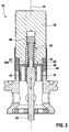
- FIG. 2 shows a partial sectional view of the electromagnetic actuator 10 of a second embodiment of the quantity control valve 12, which the first embodiment of the FIG. 1 is essentially similar.
- the armature spring 25 is struck in a central axial bore of the pole core 38 on a clamping piece 46.
- the armature 18 has on an end face facing the pole core 38 an annular contact surface 48, which is approximately congruent to the annular stop 39.
- the stop 39 is spaced from the contact surface 48 by an axial dimension (without reference numeral).
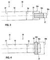
- FIG. 3 shows a first schematic representation of cold working at an end portion 52 of a ferrimagnetic or ferromagnetic rod-shaped ferromagnetic material 51.
- the drawing shows how a first cross-section 54 of the rod-shaped material 51 is cold formed by reducing an end portion 50a of the end portion 52 to a second cross-section 56a can be or has been reshaped.
- the reduction of the cross-section 54 is effected by means of radial swaging, by means of rolling, by means of axial swaging, by means of tumbling presses or a combination thereof.
- the end portion 50b thus represents a section on which the stop 39 forming end face 37 of the pole core 38 is present.
- the end portion 50b is hatched in the drawing and has increased strength due to cold working. Between the end portion 50b and the remaining end portion 52, a dashed conical transition region 55 is present.
- the thus prepared pole core 38 is separated at a separation point 57 of the rod-shaped material 51, but previously possibly also formed by machining, for example by turning.
- FIG. 4 shows a second schematic representation of a to the FIG. 3 alternative cold forming at the end portion 50a.
- the drawing shows how the first cross-section 54 of the rod-shaped material 51 at the end region 50a by cold forming by enlargement on a second cross section 56b can be transformed or reshaped. This is preferably also done with the at FIG. 3 described processing options.
- the in the end portion 50b of the pole core 38 in the FIGS. 3 and 4 cold-formed material has due to the cold forming an increased hardness.
- the hard chrome layer 60 may be applied to the end face 37 of the end region 50b.
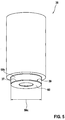
- FIG. 5 shows a spatial view of the pole core 38 in one on the FIG. 3 following finished state.
- the end portion 50b of the pole core 38 shown in the drawing below has a second cross section 56c reduced in relation to the second cross section 56a as a result of machining.
- the front side 37 has been machined and has a respect to the FIG. 3 changed axial final dimension (without reference numeral) on.
- a hard chrome layer 60 is applied by electroplating.
- FIG. 6 shows a flowchart for performing a method for producing the pole core 38.
- a block 62 represents a first step in which the rod-shaped material 51 is clamped in a clamping device of a lathe. The rod-shaped material 51 has a soft-annealed condition.
- a following block 64 shows a second step (a), in which the end portion 50a of the rod-shaped material 51 is plastically cold worked to the end portion 50b. This is preferably done by radial swaging and / or rolling and / or axial compression and / or tumbling.
- a following block 66 shows a third step (b), in which the end portion 52 is machined on the end portion 50b.
- a following block 68 shows a fourth step, in which the machined end portion 52 is separated from the rod-shaped material 51 at the separation point 57.
- a following block 70 shows a fifth step, in which the rod-shaped material 51 is displaced by an axial dimension in the clamping device. Thereafter, the steps described in blocks 62 to 70 are repeated until the rod-shaped material 51 is used up.
- the pole core 38 substantially retains the magnetic properties of the as-annealed condition because the material area affected by the cold working and the machining is comparatively small.
Landscapes
- Physics & Mathematics (AREA)
- Electromagnetism (AREA)
- Engineering & Computer Science (AREA)
- Power Engineering (AREA)
- Magnetically Actuated Valves (AREA)
Description
- Die Erfindung betrifft ein Magnetventil nach dem Oberbegriff des Anspruchs 1, sowie ein Verfahren nach dem nebengeordneten Patentanspruch.
- Vom Markt her bekannt sind Magnetventile für eine Vielzahl von Anwendungen. Beispielsweise können Mengensteuerventile für Kraftstoff-Hochdruckpumpen mittels magnetischer Kraft eine durch die Kraftstoff-Hochdruckpumpe geförderte Kraftstoffmenge steuern. Dadurch kann eine definierte Fördermenge des Kraftstoffs unter hohem Druck in einen Druckspeicher ("Rail") für eine Brennkraftmaschine gepumpt werden. Häufig sind die Magnetventile derart ausgeführt, dass bei Bestromung einer Spule ein Anker gegen einen Anschlag, beispielsweise an einem Polkern, anschlagen kann. Ein Solenoïd-Aktnator, geeignet für Einspritzventile, wobei Anker und Pol-Teile thermisch gehärtet sind, ist bekannt von
US 5 752 308 . - Das der Erfindung zugrunde liegende Problem wird durch ein Magnetventil nach Anspruch 1, sowie durch ein Verfahren nach dem nebengeordneten Anspruch gelöst. Vorteilhafte Weiterbildungen sind in Unteransprüchen angegeben. Für die Erfindung wichtige Merkmale finden sich ferner in der nachfolgenden Beschreibung und in den Zeichnungen, wobei die Merkmale sowohl in Alleinstellung als auch in unterschiedlichen Kombinationen für die Erfindung wichtig sein können, ohne dass hierauf nochmals explizit hingewiesen wird.
- Die Erfindung weist den Vorteil auf, dass ein Magnetventil besonders verschleißfest ausgeführt werden kann, wobei ein Polkern gute weichmagnetische Eigenschaften aufweist und ein an einem Endbereich des Polkerns gebildeter Ankeranschlag besonders dauerhaft ist. Der Ankeranschlag kann eine magnetische Trennschicht, beispielsweise eine Hartchromschicht aufweisen, wobei ein Material des Polkerns in einer Umgebung der Hartchromschicht vergleichsweise fest ist, obwohl der Polkern insgesamt aus einem an sich eher weichen Material hergestellt ist. Weiterhin kann mittels eines erfindungsgemäßen Verfahrens zur Herstellung des Magnetventils ein Polkern besonders präzise und zugleich effizient hergestellt werden. Durch ein sequenzielles Bearbeiten in vorzugsweise einer Einspannung wird eine vergleichsweise hohe Positioniergenauigkeit des umgeformten Materialbereichs erreicht. Die Herstellung ermöglicht ein formgenaues Bearbeiten und ist zudem vergleichsweise kostengünstig.
- Die Erfindung betrifft ein Magnetventil, insbesondere ein Mengensteuerventil einer Kraftstoff-Hochdruckpumpe, mit einem Polkern und einem axial bewegbaren Anker, wobei eine Stirnseite des Polkerns einen Anschlag für den Anker bildet. Erfindungsgemäß ist der Polkern aus einem ferritischen Material, beispielsweise einem nichtrostenden ferritischen Stahl, hergestellt, und die den Anschlag bildende Stirnseite des Polkerns ist an einem durch eine plastische Kaltumformung hergestellten Abschnitt vorhanden. Dabei wird von der Überlegung ausgegangen, dass ein weichgeglühter nichtrostender ferritischer Stahl - beispielsweise aus einem "1.4511 "-Werkstoff - gute weichmagnetische Eigenschaften aufweist, wobei der Stahl jedoch mechanisch ebenfalls vergleichsweise "weich" ist. Eine Kaltumformung des Stahls kann diesen zwar insgesamt härter machen, wobei aber die magnetischen Eigenschaften des Polkerns beeinträchtigt werden. Daher ist erfindungsgemäß nur der dem Anker zugewandte Endbereich bzw. die betreffende Stirnseite des Polkerns plastisch kaltverformt ausgeführt. Darüber hinaus kann die Erfindung gegebenenfalls auch für andere Materialien als ferritische Stähle und auch für andere Einsatzfälle als Magnetventile angewendet werden.
- Die Dauerfestigkeit des Magnetventils wird verbessert, wenn der Anschlag mit einer Hartchromschicht beschichtet ist. Die Hartchromschicht macht den Anschlag härter und ermöglicht zugleich eine magnetische Trennung, wenn der Anker angeschlagen ist, wodurch ein magnetisches Festkleben des Ankers an dem Anschlag zumindest reduziert ist. Die plastische Kaltumformung des Polkerns ermöglicht dabei einen besonders festen Untergrund für die vorzugsweise galvanisch aufgebrachte Hartchromschicht, wodurch die Dauerfestigkeit und die Dauerhaftung der Hartchromschicht am Untergrund verbessert wird.
- Insbesondere sieht die Erfindung vor, dass die den Anschlag bildende Stirnseite des Polkerns an einem durch radiales Rundhämmern und/oder Walzen und/oder axiales Stauchen und/oder Taumelpressen hergestellten Abschnitt vorhanden ist. Diese Herstellschritte ermöglichen auf einfache und kostengünstige Weise eine an der Stirnseite lokal begrenzte plastische Kaltumformung. Dadurch weist lediglich der dem Anker zugewandte Endbereich bzw. die Stirnseite des Polkerns eine vergrößerte Härte auf, wodurch - insbesondere zusammen mit der Hartchromschicht - die Dauerfestigkeit des Magnetventils erhöht wird. Zugleich sind die übrigen Abschnitte des Polkerns nicht kalt umgeformt und weisen daher gute weichmagnetische Eigenschaften auf.
- Das Magnetventil arbeitet präziser, wenn die den Anschlag bildende Stirnseite des Polkerns an einem nach der plastischen Kaltumformung spanend bearbeiteten Abschnitt vorhanden ist. Dadurch weist die Stirnseite zugleich eine große Härte und besonders geringe mechanische Toleranzen auf.
- Weiterhin betrifft die Erfindung ein Verfahren zur Herstellung des Magnetventils, wobei der Polkern für das Magnetventil mittels der nachfolgenden Schritte hergestellt wird:
- (a) ein Endabschnitt eines ferrimagnetischen oder ferromagnetischen Materials wird plastisch umgeformt;
- (b) der Endabschnitt wird spanend bearbeitet.
- Die im ersten Schritt (a) erfolgende plastische Umformung Kaltermöglicht die für den Anschlag bzw. für den Untergrund der Hartchromschicht erforderliche große Härte. Die im zweiten Schritt (b) durchgeführte spanende Bearbeitung ermöglicht besonders kleine mechanische Toleranzen. Dies ist insbesondere an dem Anschlag von Vorteil, damit im Betrieb des Magnetventils ein jeweils minimaler bzw. optimaler Luftspalt gebildet werden kann. Die spanende Bearbeitung erfolgt nur so weit, dass ein genügendes Volumen des plastisch umgeformtes Materials an dem Endbereich des Polkerns verbleibt.
- Vorzugsweise wird das Verfahren derart durchgeführt, dass die plastische Kalt-Umformung mittels radialem Rundhämmern und/oder mittels Walzen und/oder mittels axialem Stauchen und/oder mittels Taumelpressen erfolgt. Dies sind besonders geeignete Möglichkeiten zur plastischen Umformung, wenn nur ein vergleichsweise kleines Volumen des ferrimagnetischen oder ferromagnetischen Materials plastisch umgeformt werden soll.
- Das erfindungsgemäße Verfahren kann mit den folgenden Schritten besonders präzise und effizient durchgeführt werden:
- vor dem Schritt (a): Einspannen eines stangenförmigen Materials in eine Spannvorrichtung;
- nach dem Schritt (b): Abtrennen des bearbeiteten Endabschnitts, Verschieben des stangenförmigen Materials um ein axiales Maß in der Spannvorrichtung und Wiederholen der bisherigen Schritte.
- Das vor dem Schritt (a) eingespannte stangenförmige Material stellt eine Rohform dar, aus der eine Anzahl von Polkernen nacheinander hergestellt wird. Dazu wird das stangenförmige Material beispielsweise in einen Drehautomaten (Zerspanungsmaschine) eingespannt. Im Schritt (a) wird dann der jeweilige Endabschnitt der Rohform mittels der oben beschriebenen Bearbeitungsmöglichkeiten plastisch Kaltumgeformt. Danach erfolgt im Schritt (b) - vorzugsweise ohne einen Umspannvorgang - die spanende Bearbeitung des jeweiligen Endabschnitts der Rohform auf ein vorgegebenes Maß. Nach dem Schritt (b) wird der bearbeitete Endabschnitt, also der im Wesentlichen fertige Polkern, abgetrennt. Danach werden das stangenförmige Material in etwa um ein axiales Maß des Polkerns in Richtung eines Bearbeitungswerkzeugs in der Spannvorrichtung verschoben und die bisherigen Schritte wiederholt. Dadurch entfällt nicht nur mindestens ein Umspannvorgang, sondern ebenso ein jeweiliges neues Positionieren des Werkstücks, wodurch zusätzliche Herstelltoleranzen vermieden werden können.
- Nachfolgend werden beispielhafte Ausführungsformen der Erfindung unter Bezugnahme auf die Zeichnung erläutert. In der Zeichnung zeigen:
- Figur 1
- eine teilweise Schnittansicht einer ersten Ausführungsform eines Mengensteuerventils;
- Figur 2
- eine teilweise Schnittansicht einer elektromagnetischen Betätigungseinrichtung einer zweiten Ausführungsform des Mengensteuerventils;
- Figur 3
- eine schematische Darstellung einer Kaltumformung durch Verringerung eines Querschnitts;
- Figur 4
- eine schematische Darstellung einer Kaltumformung durch Vergrößerung des Querschnitts;
- Figur 5
- ein Polkern der elektromagnetischen Betätigungseinrichtung von
Figur 2 in einer räumlichen Ansicht; und - Figur 6
- ein Flussdiagramm eines Verfahrens zur Herstellung des Polkerns.
- Es werden für funktionsäquivalente Elemente und Größen in allen Figuren auch bei unterschiedlichen Ausführungsformen die gleichen Bezugszeichen verwendet.
- Die
Figur 1 zeigt eine teilweise Schnittansicht einer elektromagnetischen Betätigungseinrichtung 10 einer ersten Ausführungsform eines Mengensteuerventils 12. Das Mengensteuerventil 12 ist Teil einer (nicht gezeigten) Hochdruckpumpe eines Kraftstoffsystems zur Benzin-Direkteinspritzung einer Brennkraftmaschine. Dargestellt sind unter anderem einige Abschnitte eines Gehäuses 14, ein axial zu einer Längsachse 16 bewegbarer Anker 18, und eine Spule 20. Der Anker 18 weist axiale Bohrungen 19 auf und ist in einem Führungsabschnitt 22 aufgenommen. Weiterhin ist der Anker 18 starr mit einer Ventilnadel 24 gekoppelt. Eine als Schraubenfeder ausgeführte Ankerfeder 25 drückt den Anker 18 in der Zeichnung vertikal nach unten. Ein in der Zeichnung unterer Endabschnitt der Ventilnadel 24 kann eine Ventilplatte 28 gegen die Kraft einer an der Ventilplatte 28 angreifenden Ventilfeder 30 beaufschlagen. Die Ventilplatte 28 arbeitet gegen einen Ventilsitz 32. Ein in der Zeichnung unterer Endbereich des Gehäuses 14 umfasst einen Topf 34, gegen den sich die Ventilfeder 30 abstützt. Die elektromagnetische Betätigungseinrichtung 10 bzw. das Mengensteuerventil 12 sind im Wesentlichen rotationssymmetrisch um die Längsachse 16 ausgebildet, jedoch in der Zeichnung nur rechts der Längsachse 16 dargestellt. - Der Führungsabschnitt 22 umschließt den Anker 18 radial und führt den Magnetfluss als Teil eines magnetischen Kreises, der vorliegend durch eine in der Zeichnung nur angedeutete magnetische Rückführung 36 vervollständigt wird. Weiterhin umfasst der Führungsabschnitt 22 einen im oberen Bereich der Zeichnung angeordneten topfförmigen Polkern 38. Der Polkern 38 weist an einer dem Anker 18 zugewandten Stirnseite 37 einen ringförmigen Anschlag 39 auf, an dem der Anker 18 anschlagen kann. Der Anschlag 39 ist beispielsweise mittels einer Hartchromschicht 60 (siehe auch
Figur 5 ) ausgeführt. - Die elektromagnetische Betätigungseinrichtung 10 ist vorliegend in einem unbestromten Zustand dargestellt. Die Ankerfeder 25 beaufschlagt den Anker 18 zusammen mit der Ventilnadel 24 in der Zeichnung vertikal nach unten, so dass die Ventilplatte 28 gegen die Kraft der Ventilfeder 30 ebenfalls nach unten beaufschlagt wird und einen Spalt 40, durch welchen Kraftstoff strömen kann, freigibt.
- Wird die Spule 20 bestromt, so wird der Anker 18 von dem Polkern 38 durch Magnetkraft bis an den Anschlag 39 angezogen. Damit wird auch die Ventilnadel 24 von der Ventilplatte 28 abgehoben, so dass die Ventilfeder 30 die Ventilplatte 28 gegen den Ventilsitz 32 drücken kann, und das Mengensteuerventil 12 somit schließt.
- Die magnetischen Materialkomponenten der elektromagnetischen Betätigungseinrichtung 10 führen den bei Bestromung der Spule 20 erzeugten magnetischen Fluss und bilden vorliegend den relativ größten Volumenanteil des Führungsabschnitts 22. In der Nähe des Anschlags 39 ist eine nichtmagnetische Komponente 44 derart angeordnet, dass ein in der Zeichnung oberer und unterer Bereich des Führungsabschnitts 22 magnetisch getrennt sind.
- Die
Figur 2 zeigt eine teilweise Schnittansicht der elektromagnetischen Betätigungseinrichtung 10 einer zweiten Ausführungsform des Mengensteuerventils 12, welche der ersten Ausführungsform derFigur 1 im Wesentlichen ähnlich ist. In einem in der Zeichnung oberen Abschnitt ist die Ankerfeder 25 in einer zentrischen axialen Bohrung des Polkerns 38 an einem Klemmstück 46 angeschlagen. Der Anker 18 weist an einer dem Polkern 38 zugewandten Stirnseite eine ringförmige Kontaktfläche 48 auf, welche in etwa deckungsgleich zu dem ringförmigen Anschlag 39 ist. Vorliegend ist der Anschlag 39 von der Kontaktfläche 48 um eine axiales Maß (ohne Bezugszeichen) beabstandet. -
Figur 3 zeigt eine erste schematische Darstellung einer Kaltumformung an einem Endabschnitt 52 eines nichtrostenden ferrimagnetischen oder ferromagnetischen stangenförmigen Materials 51. Die Zeichnung zeigt, wie ein erster Querschnitt 54 des stangenförmigen Materials 51 an einem Endbereich 50a des Endabschnitts 52 mittels Kaltumformung durch Verringerung auf einen zweiten Querschnitt 56a umgeformt werden kann bzw. umgeformt wurde. Vorzugsweise erfolgt die Verringerung des Querschnitts 54 mittels radialem Rundhämmern, mittels Walzen, mittels axialem Stauchen, mittels Taumelpressen oder einer Kombination daraus. - Aus dem Endbereich 50a des Endabschnitts 52 des stangenförmigen Materials 51 wird bzw. wurde somit ein Endbereich 50b des Polkerns 38. Der Endbereich 50b stellt also einen Abschnitt dar, an dem die den Anschlag 39 bildende Stirnseite 37 des Polkerns 38 vorhanden ist. Der Endbereich 50b ist in der Zeichnung schraffiert dargestellt und weist infolge der Kaltumformung eine erhöhte Festigkeit auf. Zwischen dem Endbereich 50b und dem übrigen Endabschnitt 52 ist ein gestrichelt gezeichneter konischer Übergangsbereich 55 vorhanden. In einem der auf die
Figur 3 folgenden Bearbeitungsschritte wird der derart vorgefertigte Polkern 38 an einer Trennstelle 57 von dem stangenförmigen Material 51 abgetrennt, zuvor aber ggf. noch spanend geformt, beispielsweise durch Drehen. -
Figur 4 zeigt eine zweite schematische Darstellung einer zu derFigur 3 alternativen Kaltumformung an dem Endbereich 50a. Die Zeichnung zeigt, wie der erste Querschnitt 54 des stangenförmigen Materials 51 an dem Endbereich 50a mittels Kaltumformung durch Vergrößerung auf einen zweiten Querschnitt 56b umgeformt werden kann bzw. umgeformt wurde. Dies erfolgt vorzugsweise ebenfalls mit den bei derFigur 3 beschriebenen Bearbeitungsmöglichkeiten. - Das in dem Endbereich 50b des Polkerns 38 in den
Figuren 3 und 4 kalt umgeformte Material weist infolge der Kaltumformung eine vergrößerte Härte auf. Auf die Stirnseite 37 des Endbereichs 50b kann gegebenenfalls die Hartchromschicht 60 aufgebracht werden. -
Figur 5 zeigt eine räumliche Ansicht des Polkerns 38 in einem auf dieFigur 3 folgenden fertigen Zustand. Der in der Zeichnung unten dargestellte Endbereich 50b des Polkerns 38 weist infolge einer spanenden Bearbeitung einen in Bezug auf den zweiten Querschnitt 56a verminderten zweiten Querschnitt 56c auf. Ebenso wurde die Stirnseite 37 spanend bearbeitet und weist ein in Bezug auf dieFigur 3 verändertes axiales Endmaß (ohne Bezugszeichen) auf. Auf der Stirnseite 37 ist eine Hartchromschicht 60 galvanisch aufgetragen. -
Figur 6 zeigt ein Flussdiagramm zur Durchführung eines Verfahrens zur Herstellung des Polkerns 38. Ein Block 62 stellt einen ersten Schritt dar, bei dem das stangenförmige Material 51 in eine Spannvorrichtung eines Drehautomaten eingespannt wird. Das stangenförmige Material 51 weist einen weichgeglühten Zustand auf. Ein folgender Block 64 zeigt einen zweiten Schritt (a), bei dem der Endbereich 50a des stangenförmigen Materials 51 plastisch mittels Kaltumformung zu dem Endbereich 50b umgeformt wird. Dies erfolgt vorzugsweise durch radiales Rundhämmern und/oder Walzen und/oder axiales Stauchen und/oder Taumelpressen. - Ein folgender Block 66 zeigt einen dritten Schritt (b), bei dem der Endabschnitt 52 an dem Endbereich 50b spanend bearbeitet wird. Ein folgender Block 68 zeigt einen vierten Schritt, bei dem der bearbeitete Endabschnitt 52 von dem stangenförmigen Material 51 an der Trennstelle 57 abgetrennt wird. Ein folgender Block 70 zeigt einen fünften Schritt, bei dem das stangenförmige Material 51 um ein axiales Maß in der Spannvorrichtung verschoben wird. Danach werden die in den Blöcken 62 bis 70 beschriebenen Schritte wiederholt, bis das stangenförmige Material 51 aufgebraucht ist.
- Durch die beschriebenen Verfahrensschritte wird die für einen dauerhaften Betrieb des Magnetventils bzw. des Mengensteuerventils 12 erforderliche Härte des Anschlags 39 erreicht. Zugleich behält der Polkern 38 im Wesentlichen die magnetischen Eigenschaften des weichgeglühten Zustands bei, weil der durch die Kaltumformung und die spanende Bearbeitung betroffene Materialbereich vergleichsweise klein ist.
Claims (7)
- Magnetventil, insbesondere Mengensteuerventil (12) einer Kraftstoff-Hochdruckpumpe, mit einem Polkern (38) und einem axial bewegbaren Anker (18), wobei eine Stirnseite (37) des Polkerns (38) einen Anschlag (39) für den Anker (18) bildet, dadurch gekennzeichnet, dass der Polkern (38) aus einem ferritischen Material, insbesondere einem nichtrostenden ferritischen Stahl, und die den Anschlag (39) bildende Stirnseite (37) des Polkerns (38) an einem durch eine plastische Kaltumformung hergestellten Abschnitt (50b) vorhanden ist.
- Magnetventil nach Anspruch 1, dadurch gekennzeichnet, dass der Anschlag (39) mit einer Hartchromschicht (60) beschichtet ist.
- Magnetventil nach einem der Ansprüche 1 oder 2, dadurch gekennzeichnet, dass die den Anschlag (39) bildende Stirnseite (37) des Polkerns (38) an einem durch radiales Rundhämmern und/oder Walzen und/oder axiales Stauchen und/oder Taumelpressen hergestellten Abschnitt (50b) vorhanden ist.
- Magnetventil nach einem der vorhergehenden Ansprüche, dadurch gekennzeichnet, dass die den Anschlag (39) bildende Stirnseite (37) des Polkerns (38) an einem nach der plastischen Kaltumformung spanend bearbeiteten Abschnitt (50b) vorhanden ist.
- Verfahren zur Herstellung eines Magnetventils, dadurch gekennzeichnet, dass ein Polkern (38) für das Magnetventil mittels der nachfolgenden Schritte hergestellt wird:(a) ein Endabschnitt (52) eines ferrimagnetischen oder ferromagnetischen Materials (51) wird plastisch Kaltumgeformt;(b) der Endabschnitt (52) wird spanend bearbeitet.
- Verfahren nach Anspruch 5, dadurch gekennzeichnet, dass die plastische Umformung mittels radialem Rundhämmern und/oder mittels Walzen und/oder mittels axialem Stauchen und/oder mittels Taumelpressen erfolgt.
- Verfahren nach einem der Ansprüche 5 oder 6, dadurch gekennzeichnet, dass es folgende Schritte umfasst:vor dem Schritt (a): Einspannen eines stangenförmigen Materials (51) in eine Spannvorrichtung;nach dem Schritt (b): Abtrennen des bearbeiteten Endabschnitts (52), Verschieben des stangenförmigen Materials (51) um ein axiales Maß in der Spannvorrichtung und Wiederholen der bisherigen Schritte.
Applications Claiming Priority (2)
| Application Number | Priority Date | Filing Date | Title |
|---|---|---|---|
| DE201110089999 DE102011089999A1 (de) | 2011-12-27 | 2011-12-27 | Magnetventil, insbesondere Mengensteuerventil einer Kraftstoff-Hochdruckpumpe |
| PCT/EP2012/073049 WO2013097984A1 (de) | 2011-12-27 | 2012-11-20 | Magnetventil, insbesondere mengensteuerventil einer kraftstoff-hochdruckpumpe |
Publications (2)
| Publication Number | Publication Date |
|---|---|
| EP2798650A1 EP2798650A1 (de) | 2014-11-05 |
| EP2798650B1 true EP2798650B1 (de) | 2016-02-03 |
Family
ID=47263276
Family Applications (1)
| Application Number | Title | Priority Date | Filing Date |
|---|---|---|---|
| EP12794233.2A Not-in-force EP2798650B1 (de) | 2011-12-27 | 2012-11-20 | Magnetventil, insbesondere mengensteuerventil einer kraftstoff-hochdruckpumpe |
Country Status (5)
| Country | Link |
|---|---|
| EP (1) | EP2798650B1 (de) |
| KR (1) | KR101532970B1 (de) |
| CN (1) | CN104025215B (de) |
| DE (1) | DE102011089999A1 (de) |
| WO (1) | WO2013097984A1 (de) |
Families Citing this family (7)
| Publication number | Priority date | Publication date | Assignee | Title |
|---|---|---|---|---|
| DE102014215466A1 (de) | 2014-08-05 | 2016-02-11 | Robert Bosch Gmbh | Magnetventil |
| DE102015105489A1 (de) * | 2015-04-10 | 2016-10-13 | Bürkert Werke GmbH | Aktor |
| DE102015212387A1 (de) * | 2015-07-02 | 2017-01-05 | Robert Bosch Gmbh | Elektromagnetisch betätigbares Saugventil für eine Hochdruckpumpe sowie Verfahren zur Herstellung eines solchen Saugventils |
| WO2019102909A1 (ja) * | 2017-11-22 | 2019-05-31 | イーグル工業株式会社 | ソレノイドバルブ |
| KR101987455B1 (ko) | 2018-01-26 | 2019-09-30 | (주)모토닉 | 전자식 솔레노이드 밸브의 조립 구조 |
| KR101987456B1 (ko) | 2018-01-26 | 2019-06-12 | (주)모토닉 | 전자식 솔레노이드 밸브의 슬리브 구조 |
| DE102019215643A1 (de) * | 2019-10-11 | 2021-04-15 | Robert Bosch Gmbh | Einspritzventil |
Family Cites Families (11)
| Publication number | Priority date | Publication date | Assignee | Title |
|---|---|---|---|---|
| US2997633A (en) * | 1958-05-13 | 1961-08-22 | Westinghouse Electric Corp | Electromagnetic actuated devices |
| EP0452580B1 (de) * | 1990-04-19 | 1999-06-23 | Seiko Epson Corporation | Kunstharzgebundener Magnet und dessen Herstellungsverfahren |
| US5488340A (en) * | 1994-05-20 | 1996-01-30 | Caterpillar Inc. | Hard magnetic valve actuator adapted for a fuel injector |
| JPH10169822A (ja) * | 1996-12-06 | 1998-06-26 | Toyota Motor Corp | 電磁弁 |
| DE19834121A1 (de) * | 1998-07-29 | 2000-02-03 | Bosch Gmbh Robert | Kraftstoffversorgungsanlage einer Brennkraftmaschine |
| JP2002004013A (ja) * | 2000-06-16 | 2002-01-09 | Keihin Corp | 電磁弁用コア |
| DE10256662A1 (de) * | 2002-12-04 | 2004-06-17 | Robert Bosch Gmbh | Brennstoffeinspritzventil |
| CN101176905B (zh) * | 2003-12-22 | 2011-11-09 | 本田技研工业株式会社 | 构件的成形方法、气门导管及其成形方法、筒状构件的成形方法 |
| JP4707443B2 (ja) * | 2005-04-21 | 2011-06-22 | 株式会社タカコ | 電磁ソレノイドおよびその部品ならびに製造方法 |
| JP4790441B2 (ja) * | 2006-02-17 | 2011-10-12 | 日立オートモティブシステムズ株式会社 | 電磁燃料噴射弁及びその組立て方法 |
| DE102007028600B4 (de) * | 2007-06-19 | 2011-06-22 | ETO MAGNETIC GmbH, 78333 | Elektromagnetische Stellvorrichtung |
-
2011
- 2011-12-27 DE DE201110089999 patent/DE102011089999A1/de not_active Withdrawn
-
2012
- 2012-11-20 KR KR1020147009595A patent/KR101532970B1/ko not_active Expired - Fee Related
- 2012-11-20 EP EP12794233.2A patent/EP2798650B1/de not_active Not-in-force
- 2012-11-20 CN CN201280064799.XA patent/CN104025215B/zh not_active Expired - Fee Related
- 2012-11-20 WO PCT/EP2012/073049 patent/WO2013097984A1/de not_active Ceased
Also Published As
| Publication number | Publication date |
|---|---|
| DE102011089999A1 (de) | 2013-06-27 |
| KR101532970B1 (ko) | 2015-07-02 |
| KR20140064949A (ko) | 2014-05-28 |
| WO2013097984A1 (de) | 2013-07-04 |
| EP2798650A1 (de) | 2014-11-05 |
| CN104025215B (zh) | 2017-04-26 |
| CN104025215A (zh) | 2014-09-03 |
Similar Documents
| Publication | Publication Date | Title |
|---|---|---|
| EP2798650A1 (de) | Magnetventil, insbesondere mengensteuerventil einer kraftstoff-hochdruckpumpe | |
| EP0683862B1 (de) | Elektromagnetisch betätigbares ventil | |
| EP0886727B1 (de) | Elektromagnetisch betätigbares ventil | |
| DE69704989T2 (de) | Ein elektromagnetisch betätigbares Ventil | |
| EP0683861B1 (de) | Elektromagnetisch betätigbares ventil | |
| EP2097913B1 (de) | Verfahren zur herstellung eines festen magnetkreisbauteils | |
| WO2012123086A1 (de) | Elektromagnetischer aktor | |
| WO2000040855A1 (de) | Brennstoffeinspritzventil | |
| DE102011078407A1 (de) | Schaltventil zur Steuerung eines Kraftstoffinjektors und Kraftstoffinjektor | |
| DE112006001605B4 (de) | Elektromagnetische Betätigungsvorrichtung und Verfahren zur Steuerung eines Strömungsmittelflusses | |
| DE112021002276B4 (de) | Vorhubeinstellungsverfahren für ein kraftstoffeinspritzventil | |
| DE4421947A1 (de) | Elektromagnetisch betätigbares Ventil | |
| DE112018004340T5 (de) | Kraftstoffeinspritzventil | |
| WO2005061150A1 (de) | Verfahren zur herstellung eines hülsenförmigen gehäuses aus mehreren flachen blechen | |
| DE202015100601U1 (de) | Sitzventil zum zumindest teilweisen Verschließen und Öffnen eines Leitungssystems | |
| WO2010000507A1 (de) | Magnetventil, kraftstoff-injektor sowie herstellungsverfahren | |
| DE112018004339B4 (de) | Kraftstoffeinspritzventil | |
| WO2018028865A1 (de) | Elektromagnetisch betätigbares saugventil und kraftstoff-hochdruckpumpe | |
| DE102009046830B4 (de) | Common-Rail-System mit einem Mengensteuerventil | |
| DE3501973A1 (de) | Brennstoff-einspritzduese | |
| DE102009045623A1 (de) | Kraftstoff-Injektor | |
| DE4108665A1 (de) | Einstellbuchse fuer ein elektromagnetisch betaetigbares ventil | |
| EP2643619B1 (de) | Ventileinrichtung mit einem wenigstens abschnittsweise zylindrischen bewegungselement | |
| DE102012210956A1 (de) | Verfahren zur Herstellung eines Gehäuses, insbesondere eines Ventilgehäuses | |
| DE102009046079A1 (de) | Mengensteuerventil, insbesondere zur Mengensteuerung einer Kraftstoff-Hochdruckpumpe |
Legal Events
| Date | Code | Title | Description |
|---|---|---|---|
| PUAI | Public reference made under article 153(3) epc to a published international application that has entered the european phase |
Free format text: ORIGINAL CODE: 0009012 |
|
| 17P | Request for examination filed |
Effective date: 20140728 |
|
| AK | Designated contracting states |
Kind code of ref document: A1 Designated state(s): AL AT BE BG CH CY CZ DE DK EE ES FI FR GB GR HR HU IE IS IT LI LT LU LV MC MK MT NL NO PL PT RO RS SE SI SK SM TR |
|
| DAX | Request for extension of the european patent (deleted) | ||
| GRAP | Despatch of communication of intention to grant a patent |
Free format text: ORIGINAL CODE: EPIDOSNIGR1 |
|
| INTG | Intention to grant announced |
Effective date: 20151002 |
|
| GRAS | Grant fee paid |
Free format text: ORIGINAL CODE: EPIDOSNIGR3 |
|
| GRAA | (expected) grant |
Free format text: ORIGINAL CODE: 0009210 |
|
| AK | Designated contracting states |
Kind code of ref document: B1 Designated state(s): AL AT BE BG CH CY CZ DE DK EE ES FI FR GB GR HR HU IE IS IT LI LT LU LV MC MK MT NL NO PL PT RO RS SE SI SK SM TR |
|
| REG | Reference to a national code |
Ref country code: GB Ref legal event code: FG4D Free format text: NOT ENGLISH |
|
| REG | Reference to a national code |
Ref country code: AT Ref legal event code: REF Ref document number: 774035 Country of ref document: AT Kind code of ref document: T Effective date: 20160215 Ref country code: CH Ref legal event code: EP |
|
| REG | Reference to a national code |
Ref country code: IE Ref legal event code: FG4D Free format text: LANGUAGE OF EP DOCUMENT: GERMAN |
|
| REG | Reference to a national code |
Ref country code: DE Ref legal event code: R096 Ref document number: 502012005922 Country of ref document: DE |
|
| REG | Reference to a national code |
Ref country code: LT Ref legal event code: MG4D Ref country code: NL Ref legal event code: MP Effective date: 20160203 |
|
| PG25 | Lapsed in a contracting state [announced via postgrant information from national office to epo] |
Ref country code: ES Free format text: LAPSE BECAUSE OF FAILURE TO SUBMIT A TRANSLATION OF THE DESCRIPTION OR TO PAY THE FEE WITHIN THE PRESCRIBED TIME-LIMIT Effective date: 20160203 Ref country code: GR Free format text: LAPSE BECAUSE OF FAILURE TO SUBMIT A TRANSLATION OF THE DESCRIPTION OR TO PAY THE FEE WITHIN THE PRESCRIBED TIME-LIMIT Effective date: 20160504 Ref country code: FI Free format text: LAPSE BECAUSE OF FAILURE TO SUBMIT A TRANSLATION OF THE DESCRIPTION OR TO PAY THE FEE WITHIN THE PRESCRIBED TIME-LIMIT Effective date: 20160203 Ref country code: NO Free format text: LAPSE BECAUSE OF FAILURE TO SUBMIT A TRANSLATION OF THE DESCRIPTION OR TO PAY THE FEE WITHIN THE PRESCRIBED TIME-LIMIT Effective date: 20160503 Ref country code: HR Free format text: LAPSE BECAUSE OF FAILURE TO SUBMIT A TRANSLATION OF THE DESCRIPTION OR TO PAY THE FEE WITHIN THE PRESCRIBED TIME-LIMIT Effective date: 20160203 |
|
| PG25 | Lapsed in a contracting state [announced via postgrant information from national office to epo] |
Ref country code: SE Free format text: LAPSE BECAUSE OF FAILURE TO SUBMIT A TRANSLATION OF THE DESCRIPTION OR TO PAY THE FEE WITHIN THE PRESCRIBED TIME-LIMIT Effective date: 20160203 Ref country code: LT Free format text: LAPSE BECAUSE OF FAILURE TO SUBMIT A TRANSLATION OF THE DESCRIPTION OR TO PAY THE FEE WITHIN THE PRESCRIBED TIME-LIMIT Effective date: 20160203 Ref country code: NL Free format text: LAPSE BECAUSE OF FAILURE TO SUBMIT A TRANSLATION OF THE DESCRIPTION OR TO PAY THE FEE WITHIN THE PRESCRIBED TIME-LIMIT Effective date: 20160203 Ref country code: RS Free format text: LAPSE BECAUSE OF FAILURE TO SUBMIT A TRANSLATION OF THE DESCRIPTION OR TO PAY THE FEE WITHIN THE PRESCRIBED TIME-LIMIT Effective date: 20160203 Ref country code: LV Free format text: LAPSE BECAUSE OF FAILURE TO SUBMIT A TRANSLATION OF THE DESCRIPTION OR TO PAY THE FEE WITHIN THE PRESCRIBED TIME-LIMIT Effective date: 20160203 Ref country code: IS Free format text: LAPSE BECAUSE OF FAILURE TO SUBMIT A TRANSLATION OF THE DESCRIPTION OR TO PAY THE FEE WITHIN THE PRESCRIBED TIME-LIMIT Effective date: 20160603 Ref country code: PL Free format text: LAPSE BECAUSE OF FAILURE TO SUBMIT A TRANSLATION OF THE DESCRIPTION OR TO PAY THE FEE WITHIN THE PRESCRIBED TIME-LIMIT Effective date: 20160203 Ref country code: PT Free format text: LAPSE BECAUSE OF FAILURE TO SUBMIT A TRANSLATION OF THE DESCRIPTION OR TO PAY THE FEE WITHIN THE PRESCRIBED TIME-LIMIT Effective date: 20160603 |
|
| PG25 | Lapsed in a contracting state [announced via postgrant information from national office to epo] |
Ref country code: DK Free format text: LAPSE BECAUSE OF FAILURE TO SUBMIT A TRANSLATION OF THE DESCRIPTION OR TO PAY THE FEE WITHIN THE PRESCRIBED TIME-LIMIT Effective date: 20160203 Ref country code: EE Free format text: LAPSE BECAUSE OF FAILURE TO SUBMIT A TRANSLATION OF THE DESCRIPTION OR TO PAY THE FEE WITHIN THE PRESCRIBED TIME-LIMIT Effective date: 20160203 |
|
| REG | Reference to a national code |
Ref country code: DE Ref legal event code: R097 Ref document number: 502012005922 Country of ref document: DE |
|
| REG | Reference to a national code |
Ref country code: FR Ref legal event code: PLFP Year of fee payment: 5 |
|
| PG25 | Lapsed in a contracting state [announced via postgrant information from national office to epo] |
Ref country code: RO Free format text: LAPSE BECAUSE OF FAILURE TO SUBMIT A TRANSLATION OF THE DESCRIPTION OR TO PAY THE FEE WITHIN THE PRESCRIBED TIME-LIMIT Effective date: 20160203 Ref country code: SM Free format text: LAPSE BECAUSE OF FAILURE TO SUBMIT A TRANSLATION OF THE DESCRIPTION OR TO PAY THE FEE WITHIN THE PRESCRIBED TIME-LIMIT Effective date: 20160203 Ref country code: SK Free format text: LAPSE BECAUSE OF FAILURE TO SUBMIT A TRANSLATION OF THE DESCRIPTION OR TO PAY THE FEE WITHIN THE PRESCRIBED TIME-LIMIT Effective date: 20160203 Ref country code: CZ Free format text: LAPSE BECAUSE OF FAILURE TO SUBMIT A TRANSLATION OF THE DESCRIPTION OR TO PAY THE FEE WITHIN THE PRESCRIBED TIME-LIMIT Effective date: 20160203 |
|
| PLBE | No opposition filed within time limit |
Free format text: ORIGINAL CODE: 0009261 |
|
| STAA | Information on the status of an ep patent application or granted ep patent |
Free format text: STATUS: NO OPPOSITION FILED WITHIN TIME LIMIT |
|
| 26N | No opposition filed |
Effective date: 20161104 |
|
| PG25 | Lapsed in a contracting state [announced via postgrant information from national office to epo] |
Ref country code: BE Free format text: LAPSE BECAUSE OF NON-PAYMENT OF DUE FEES Effective date: 20161130 Ref country code: SI Free format text: LAPSE BECAUSE OF FAILURE TO SUBMIT A TRANSLATION OF THE DESCRIPTION OR TO PAY THE FEE WITHIN THE PRESCRIBED TIME-LIMIT Effective date: 20160203 Ref country code: BG Free format text: LAPSE BECAUSE OF FAILURE TO SUBMIT A TRANSLATION OF THE DESCRIPTION OR TO PAY THE FEE WITHIN THE PRESCRIBED TIME-LIMIT Effective date: 20160503 |
|
| REG | Reference to a national code |
Ref country code: CH Ref legal event code: PL |
|
| PG25 | Lapsed in a contracting state [announced via postgrant information from national office to epo] |
Ref country code: CH Free format text: LAPSE BECAUSE OF NON-PAYMENT OF DUE FEES Effective date: 20161130 Ref country code: LI Free format text: LAPSE BECAUSE OF NON-PAYMENT OF DUE FEES Effective date: 20161130 |
|
| REG | Reference to a national code |
Ref country code: IE Ref legal event code: MM4A |
|
| PG25 | Lapsed in a contracting state [announced via postgrant information from national office to epo] |
Ref country code: LU Free format text: LAPSE BECAUSE OF NON-PAYMENT OF DUE FEES Effective date: 20161130 |
|
| REG | Reference to a national code |
Ref country code: FR Ref legal event code: PLFP Year of fee payment: 6 |
|
| PG25 | Lapsed in a contracting state [announced via postgrant information from national office to epo] |
Ref country code: IE Free format text: LAPSE BECAUSE OF NON-PAYMENT OF DUE FEES Effective date: 20161120 |
|
| REG | Reference to a national code |
Ref country code: BE Ref legal event code: MM Effective date: 20161130 |
|
| PG25 | Lapsed in a contracting state [announced via postgrant information from national office to epo] |
Ref country code: HU Free format text: LAPSE BECAUSE OF FAILURE TO SUBMIT A TRANSLATION OF THE DESCRIPTION OR TO PAY THE FEE WITHIN THE PRESCRIBED TIME-LIMIT; INVALID AB INITIO Effective date: 20121120 |
|
| PG25 | Lapsed in a contracting state [announced via postgrant information from national office to epo] |
Ref country code: MC Free format text: LAPSE BECAUSE OF FAILURE TO SUBMIT A TRANSLATION OF THE DESCRIPTION OR TO PAY THE FEE WITHIN THE PRESCRIBED TIME-LIMIT Effective date: 20160203 Ref country code: CY Free format text: LAPSE BECAUSE OF FAILURE TO SUBMIT A TRANSLATION OF THE DESCRIPTION OR TO PAY THE FEE WITHIN THE PRESCRIBED TIME-LIMIT Effective date: 20160203 Ref country code: MK Free format text: LAPSE BECAUSE OF FAILURE TO SUBMIT A TRANSLATION OF THE DESCRIPTION OR TO PAY THE FEE WITHIN THE PRESCRIBED TIME-LIMIT Effective date: 20160203 |
|
| PG25 | Lapsed in a contracting state [announced via postgrant information from national office to epo] |
Ref country code: MT Free format text: LAPSE BECAUSE OF FAILURE TO SUBMIT A TRANSLATION OF THE DESCRIPTION OR TO PAY THE FEE WITHIN THE PRESCRIBED TIME-LIMIT Effective date: 20160203 |
|
| PG25 | Lapsed in a contracting state [announced via postgrant information from national office to epo] |
Ref country code: AL Free format text: LAPSE BECAUSE OF FAILURE TO SUBMIT A TRANSLATION OF THE DESCRIPTION OR TO PAY THE FEE WITHIN THE PRESCRIBED TIME-LIMIT Effective date: 20160203 Ref country code: TR Free format text: LAPSE BECAUSE OF FAILURE TO SUBMIT A TRANSLATION OF THE DESCRIPTION OR TO PAY THE FEE WITHIN THE PRESCRIBED TIME-LIMIT Effective date: 20160203 |
|
| REG | Reference to a national code |
Ref country code: AT Ref legal event code: MM01 Ref document number: 774035 Country of ref document: AT Kind code of ref document: T Effective date: 20171120 |
|
| PG25 | Lapsed in a contracting state [announced via postgrant information from national office to epo] |
Ref country code: AT Free format text: LAPSE BECAUSE OF NON-PAYMENT OF DUE FEES Effective date: 20171120 |
|
| PGFP | Annual fee paid to national office [announced via postgrant information from national office to epo] |
Ref country code: IT Payment date: 20221130 Year of fee payment: 11 Ref country code: GB Payment date: 20221123 Year of fee payment: 11 Ref country code: FR Payment date: 20221118 Year of fee payment: 11 |
|
| REG | Reference to a national code |
Ref country code: DE Ref legal event code: R084 Ref document number: 502012005922 Country of ref document: DE |
|
| GBPC | Gb: european patent ceased through non-payment of renewal fee |
Effective date: 20231120 |
|
| PG25 | Lapsed in a contracting state [announced via postgrant information from national office to epo] |
Ref country code: GB Free format text: LAPSE BECAUSE OF NON-PAYMENT OF DUE FEES Effective date: 20231120 |
|
| PG25 | Lapsed in a contracting state [announced via postgrant information from national office to epo] |
Ref country code: FR Free format text: LAPSE BECAUSE OF NON-PAYMENT OF DUE FEES Effective date: 20231130 |
|
| PG25 | Lapsed in a contracting state [announced via postgrant information from national office to epo] |
Ref country code: GB Free format text: LAPSE BECAUSE OF NON-PAYMENT OF DUE FEES Effective date: 20231120 Ref country code: FR Free format text: LAPSE BECAUSE OF NON-PAYMENT OF DUE FEES Effective date: 20231130 |
|
| PG25 | Lapsed in a contracting state [announced via postgrant information from national office to epo] |
Ref country code: IT Free format text: LAPSE BECAUSE OF NON-PAYMENT OF DUE FEES Effective date: 20231120 |
|
| PG25 | Lapsed in a contracting state [announced via postgrant information from national office to epo] |
Ref country code: IT Free format text: LAPSE BECAUSE OF NON-PAYMENT OF DUE FEES Effective date: 20231120 |
|
| PGFP | Annual fee paid to national office [announced via postgrant information from national office to epo] |
Ref country code: DE Payment date: 20250122 Year of fee payment: 13 |
|
| REG | Reference to a national code |
Ref country code: DE Ref legal event code: R119 Ref document number: 502012005922 Country of ref document: DE |