EP2798316B1 - Ultraschallwandler für ein ultraschall-durchflussmessgerät - Google Patents
Ultraschallwandler für ein ultraschall-durchflussmessgerät Download PDFInfo
- Publication number
- EP2798316B1 EP2798316B1 EP12798231.2A EP12798231A EP2798316B1 EP 2798316 B1 EP2798316 B1 EP 2798316B1 EP 12798231 A EP12798231 A EP 12798231A EP 2798316 B1 EP2798316 B1 EP 2798316B1
- Authority
- EP
- European Patent Office
- Prior art keywords
- ultrasonic
- transducer element
- housing
- electromechanical transducer
- window
- Prior art date
- Legal status (The legal status is an assumption and is not a legal conclusion. Google has not performed a legal analysis and makes no representation as to the accuracy of the status listed.)
- Active
Links
Images
Classifications
-
- G—PHYSICS
- G01—MEASURING; TESTING
- G01H—MEASUREMENT OF MECHANICAL VIBRATIONS OR ULTRASONIC, SONIC OR INFRASONIC WAVES
- G01H11/00—Measuring mechanical vibrations or ultrasonic, sonic or infrasonic waves by detecting changes in electric or magnetic properties
- G01H11/06—Measuring mechanical vibrations or ultrasonic, sonic or infrasonic waves by detecting changes in electric or magnetic properties by electric means
-
- G—PHYSICS
- G01—MEASURING; TESTING
- G01F—MEASURING VOLUME, VOLUME FLOW, MASS FLOW OR LIQUID LEVEL; METERING BY VOLUME
- G01F1/00—Measuring the volume flow or mass flow of fluid or fluent solid material wherein the fluid passes through a meter in a continuous flow
- G01F1/66—Measuring the volume flow or mass flow of fluid or fluent solid material wherein the fluid passes through a meter in a continuous flow by measuring frequency, phase shift or propagation time of electromagnetic or other waves, e.g. using ultrasonic flowmeters
- G01F1/667—Arrangements of transducers for ultrasonic flowmeters; Circuits for operating ultrasonic flowmeters
-
- H—ELECTRICITY
- H04—ELECTRIC COMMUNICATION TECHNIQUE
- H04R—LOUDSPEAKERS, MICROPHONES, GRAMOPHONE PICK-UPS OR LIKE ACOUSTIC ELECTROMECHANICAL TRANSDUCERS; ELECTRIC HEARING AIDS; PUBLIC ADDRESS SYSTEMS
- H04R31/00—Apparatus or processes specially adapted for the manufacture of transducers or diaphragms therefor
-
- Y—GENERAL TAGGING OF NEW TECHNOLOGICAL DEVELOPMENTS; GENERAL TAGGING OF CROSS-SECTIONAL TECHNOLOGIES SPANNING OVER SEVERAL SECTIONS OF THE IPC; TECHNICAL SUBJECTS COVERED BY FORMER USPC CROSS-REFERENCE ART COLLECTIONS [XRACs] AND DIGESTS
- Y10—TECHNICAL SUBJECTS COVERED BY FORMER USPC
- Y10T—TECHNICAL SUBJECTS COVERED BY FORMER US CLASSIFICATION
- Y10T29/00—Metal working
- Y10T29/49—Method of mechanical manufacture
- Y10T29/49002—Electrical device making
- Y10T29/49005—Acoustic transducer
Definitions
- the present invention relates to an ultrasonic transducer for an ultrasonic flowmeter, comprising an electromechanical transducer element biased by suitable means against an ultrasonic window of the ultrasonic transducer, wherein a first surface of the electromechanical transducer element faces the ultrasonic window.
- Ultrasonic flowmeters are widely used in process and automation technology. They allow in a simple way to determine the volume flow and / or mass flow in a pipeline.
- the known ultrasonic flowmeters often work according to the transit time difference principle.
- the different transit times of ultrasonic waves in particular ultrasonic pulses, so-called bursts, are evaluated relative to the flow direction of the fluid.
- ultrasonic pulses are sent at a certain angle to the pipe axis both with and against the flow.
- the runtime difference can be used to determine the flow velocity and, with a known diameter of the pipe section, the volume flow rate.
- the ultrasonic waves are generated or received with the help of so-called ultrasonic transducers.
- ultrasonic transducers are firmly mounted in the pipe wall of the respective pipe section.
- the ultrasonic transducers normally consist of an electromechanical transducer element, e.g. a piezoelectric element, and an ultrasonic window.
- the ultrasonic waves are generated as acoustic signals and guided to the ultrasonic window and coupled from there into the fluid or the measuring medium.
- the ultrasonic window is also called membrane.
- the adaptation layer assumes the function of the transmission of the ultrasonic signal and at the same time the reduction of a reflection caused by different acoustic impedances on boundary layers between two materials.
- the WO 2011/000634 A1 shows an ultrasonic transducer with an ultrasonic window against which an electromechanical transducer element is biased. Between the electromechanical transducer element and the ultrasonic window, a ductile solid is arranged as a coupling layer.
- the US 6,508,133 B1 shows an electromechanical transducer element is integrally connected to an ultrasonic window, wherein the surface of the electromechanical transducer element which touches the ultrasonic window is divided into a plurality of segments.
- the EP 0 766 071 A1 shows an ultrasonic transducer with a coupling means of a matrix with embedded glass hollow bodies between an electromechanical transducer element and an ultrasonic window.
- the DE 28 35 367 A1 discloses the preamble of claim 1.
- the object of the invention is to propose an ultrasonic transducer, which is suitable for flow measurement of gas.
- an ultrasonic transducer element for an ultrasonic flowmeter, in particular for gas applications, e.g. for the flow measurement of biogas, an electromechanical transducer element, such as a piezoelectric element, comprises a housing with an ultrasonic window and means adapted to bias the electromechanical transducer element against the ultrasonic window.
- a first surface of the electromechanical transducer element rests on the ultrasonic window, for example also with the interposition of a coupling agent such as grease, oil or a ductile, solid material, such as. Lead or gold.
- the electromechanical transducer element is not materially connected to the ultrasonic window, e.g. glued as it is known from the prior art. Accordingly, the first surface of the electromechanical transducer element to the ultrasonic window.
- a second surface of the electromechanical transducer element lying opposite the first surface is divided into four segments of equal size, and the segments of the second surface are galvanically connected to the means suitable for biasing.
- the inventive electromechanical transducer element cuts in planes which extend parallel to a longitudinal axis of the electromechanical transducer element.
- the cuts are not continuous, each cut forms only a deep groove.
- the first surface is planar according to a development of the invention.
- the segments each have the shape of a quarter circle, the cuts thus form in cross section through the electromechanical Transducer element a cross.
- it rejects the segmented surface of the electromechanical transducer element away from the ultrasonic window.
- the segments of the second surface lie in a plane and form the uncut portion of the second surface of the electromechanical transducer element.
- the depth of cut ie the distance from the groove bottom of the groove formed by the cut to the uncut portion of the second surface, at least 50%, in particular at least 80% of the distance from the first surface to the uncut portion of the second surface of the electromechanical transducer element which latter distance characterizes the thickness of the electromechanical transducer element.
- the first and the uncut part of the second surface of the electromechanical transducer element are in particular parallel to one another.
- the electromechanical transducer element is biased according to the invention against the ultrasonic window. This is done by means of a predetermined force which is applied to the second surface of the electromechanical transducer element by means suitable for biasing and acts in the direction of the ultrasonic window.
- suitable means are for example springs, in particular exactly one spring.
- two or more springs for example, concentrically arranged helical compression springs.
- the individual segments of the second surface of the electromechanical transducer element are electrically contacted by the spring, in particular galvanically connected to the spring.
- the means suitable for biasing comprise a helical compression spring, which has at least one complete turn extending in a plane for the galvanic contacting of the segments of the second surface of the electromechanical transducer element.
- the helical compression spring for the galvanic contacting of the segments of the second surface of the electromechanical transducer element at least two in a plane spirally extending turns on.
- the at least one, in particular, the two spirally extending turns lie on the segments of the electromechanical transducer element and thus on the uncut portion of the second surface. They lie in a plane parallel to the plane of the uncut portion of the second surface of the electromechanical transducer element.
- the two turns are considered separately, it is a flat spiral with an angle of at least 720 °.
- a conventional helical compression spring is at least partially helical or conical.
- the ultrasonic transducer has an adaptation layer, in particular for acoustic impedance matching, which limits the ultrasonic transducer to the environment, the ultrasonic window being arranged between the electromechanical transducer element and the adaptation layer.
- An acoustic impedance adaptation takes place, in particular, between the electromechanical transducer element, or the ultrasound window, and a fluid whose flow is to be measured through a pipeline by means of the ultrasound transducer.
- the acoustic impedance of the matching layer is further developed smaller than 1MRayl.
- the fluid has a lower acoustic impedance, for example 400 Rayl or 360 Rayl
- the electromechanical transducer element has a greater acoustic impedance, which are adapted to each other by the matching layer.
- the acoustic impedances of the electromechanical transducer element and the ultrasound window are in an interval of 10 to 60MRayl, in particular in the range 30 to 40 MRayl. In one embodiment of the invention, acoustic impedances from the electromechanical transducer element and the ultrasonic window are approximately equal.
- the matching layer comprises a composite matrix, for example made of resin, in particular epoxy, with spherical bodies embedded therein, for example glass spheres, glass hollow spheres or hollow ceramic spheres.
- An inventive ultrasonic transducer is thus constructed, for example, as follows. On a housing which limits the ultrasonic transducer otherwise to the environment, an adjustment layer is applied in the region of the ultrasonic window. This borders with its outer contour of the ultrasonic transducer from the environment down.
- the housing of the ultrasonic transducer may be exposed in its entirety to a fluid to be measured, or only parts thereof.
- the ultrasonic window or, if present, the matching layer forms an interface with the fluid.
- an acoustic signal from the ultrasonic transducer in the fluid on or out of this coupled is thus constructed, for example, as follows.
- an adjustment layer is applied in the region of the ultrasonic window. This borders with its outer contour of the ultrasonic transducer from the environment down.
- the housing of the ultrasonic transducer may be exposed in its entirety to a fluid to be measured, or only parts thereof.
- the ultrasonic window or, if present, the matching layer forms an interface with the fluid.
- the housing encloses the electromechanical transducer element, optionally between the electromechanical transducer element and the ultrasonic window arranged coupling means and the means for biasing the electromechanical transducer element against the ultrasonic window means.
- the ultrasound transducer is designed such that the ultrasound window electrically contacts the first surface of the electromechanical transducer element, wherein the ultrasound window and the means suitable for biasing are suitable for applying and / or tapping a voltage on the electromechanical transducer element.
- the housing is correspondingly electrically conductive and serves as an electrode for electrical contacting of the electromechanical transducer element. A separate electrode is not necessary for this.
- the galvanic connection has a resistance of at least 50 ohms.
- the resistor has a resistance of at least 1000 ohms.
- the means suitable for biasing are based on an electrically non-conductive component of the ultrasonic transducer, for example on a print, also referred to as a printed circuit board or printed circuit board, which contacts the housing.
- a separate electrical conductor for example a conductor track on the print, between the means suitable for biasing and the housing, respectively the ultrasonic window, realizes the galvanic connection, for example with the interposition of an electrical resistor of predetermined size.
- the biasing means are themselves electrically conductive.
- the ultrasonic transducer comprises a housing, which has to the electromechanical transducer element facing lugs for centering the electromechanical transducer element in the housing.
- the ultrasonic transducer comprises a housing having a cup-shaped first housing part, the bottom of which forms the ultrasonic window and on which the electromechanical transducer element is arranged, and which housing has a second housing part, with an axial stop for attachment of the ultrasonic transducer or in a measuring tube, wherein a function of the distance of each cut edge of an outer contour of the housing from the ultrasonic window to the axial stop is monotonous to a longitudinal axis of the housing, wherein the cutting edge lies in a plane in which the longitudinal axis of the housing lies.
- each angle which encloses the cutting edge with the longitudinal axis of the housing of the ultrasonic transducer, is less than 60 °.
- a further embodiment of the invention provides that the second housing part has an opening with a substantially circular cross section, wherein the electromechanical transducer element has a substantially circular cross section and wherein the radius of the electromechanical transducer element is at least 10% larger than the radius of the Opening.
- the opening serves e.g. the implementation of an electrical conductor for electrical contacting of the electromechanical transducer element.
- the first housing part is integrally connected to the second housing part, in particular welded, in particular with a laser. Since the electromechanical transducer element, possibly via a coupling layer, the ultrasonic window touches, the guided to the ultrasonic window heat, registered by the welding, must be limited so as not to damage the electromechanical transducer element and / or the coupling layer. Therefore, the temperature of the ultrasonic window should not reach more than 120 ° C, especially not more than 80 ° C.
- Stainless steel as a material for the first housing part typically has a thermal conductivity of 10 to 100 W / (m * K).
- An ultrasonic transducer designed in this way is produced according to the invention in that the electromechanical transducer element is introduced into the first or second housing part, in particular by being inserted into the first housing part, in particular placed on the ultrasonic window, for example with the interposition of a coupling agent, and then the second housing part the first housing part is placed, in particular enclosing the means for biasing, and then the first housing part are materially connected to the second housing part, in particular welded together, in particular by means of laser and in particular so that the ultrasonic window heats up to a temperature less than 80 ° C. ,
- the second housing part 3 in a lower portion of the figure has a congruent to the walls of the first housing part 2 sleeve-shaped to connect to this, but is conically tapered in an upper region, the electromechanical transducer element 5 and optionally the coupling means introduced before the connection of the first and second housing part 2 and 3.
- Stainless steel as a material for the first housing part 2 typically has a thermal conductivity of 10 to 100 W / (m * K).
- the second housing part 3 consists in particular of the same material as the first housing part 2. Therefore, the two housing parts 2 and 3 are welded in particular by means of a laser.
- two helical compression springs 10 are provided here. They generate predetermined forces in the direction of the ultrasonic window 4 and introduce them into the electromechanical transducer element 5, wherein this is thereby kept pressed against the Uttraschaitrome 4. At the same time, the biasing means 10 electrically contact the electromechanical transducer element 5. Thus, the application of one or more additional electrodes to the electromechanical transducer element 5 is superfluous.
- the biasing means 10 contact a second surface 7 of the electromechanical transducer element 5 galvanically.
- the first surface 6 of the electromechanical transducer element 5 is electrically contacted by the ultrasonic window 4.
- the first housing part 2 is for this purpose made in particular of an electrically conductive material.
- the means for biasing 10 are mounted without contact with the first housing part 2. Here they rely on a guide plate 13, which also serves as an electrical insulator. About an electrical resistance 12, the circuit is closed.
- the ultrasonic transducer 1 still has a plug 16 in a bore in the second housing part 3, through which the electrical contacting and thus the excitation and the tapping of the voltage signals at the electromechanical transducer element 5 takes place. Electrical lines are not shown here.
- the first surface 6 of the electromechanical transducer element 5 is planar and the second surface 7 is divided into four equal quarter-circle-shaped segments 9. This is done in a simple manner by a plurality of cuts 8 through the second surface 7 of the electromechanical transducer element 5.
- An adaptation layer 11 for adapting the acoustic impedances is provided here outside the housing of the ultrasound transducer 1. It is mounted on the ultrasonic window 4 so that the ultrasonic window 4 is located between the matching layer 11 and the electromechanical transducer element 5. The matching layer 11 thus touches the fluid whose flow is to be measured.
- the ultrasonic transducer 1 has an axial stop 17 in the region of the second housing part 3, which can be prestressed against an axial stop of a third housing part or a pipeline, for installation of the ultrasonic transducer 1 in a pipeline.
- This axial stop 17 may itself be configured as a sealing surface, or a seal is arranged and biased between it and the axial stop of the third housing part or the pipe.
- centering lugs in the first or second housing part 2 or 3 can be provided.
- the weld is not raised against the outer surface of the housing formed.
- a function of the distance between each cut edge of an outer contour of the housing to a longitudinal axis of the housing is thus from the ultrasonic window 4 to the axial stop 17th monotone, wherein the cutting edge lies in a plane in which lies the longitudinal axis of the housing.
Landscapes
- Physics & Mathematics (AREA)
- Engineering & Computer Science (AREA)
- General Physics & Mathematics (AREA)
- Manufacturing & Machinery (AREA)
- Acoustics & Sound (AREA)
- Signal Processing (AREA)
- Electromagnetism (AREA)
- Fluid Mechanics (AREA)
- Measuring Volume Flow (AREA)
Description
- Die vorliegende Erfindung betrifft einen Ultraschallwandler für ein Ultraschall-Durchflussmessgerät, mit einem elektromechanischen Wandlerelement, welches mit geeigneten Mitteln gegen ein Ultraschallfenster des Ultraschallwandlers vorgespannt ist, wobei eine erste Oberfläche des elektromechanischen Wandlerelements gegen das Ultraschallfenster zeigt.
- Ultraschall-Durchflussmessgeräte werden vielfach in der Prozess- und Automatisierungstechnik eingesetzt. Sie erlauben in einfacher Weise, den Volumendurchfluss und/oder Massendurchfluss in einer Rohrleitung zu bestimmen.
- Die bekannten Ultraschall-Durchflussmessgeräte arbeiten häufig nach dem Laufzeitdifferenz-Prinzip. Beim Laufzeitdifferenz-Prinzip werden die unterschiedlichen Laufzeiten von Ultraschallwellen, insbesondere Ultraschallimpulsen, so genannten Bursts, relativ zur Strömungsrichtung des Fluids ausgewertet. Hierzu werden Ultraschallimpulse in einem bestimmten Winkel zur Rohrachse sowohl mit als auch entgegen der Strömung gesendet. Aus der Laufzeitdifferenz lässt sich die Fließgeschwindigkeit und damit bei bekanntem Durchmesser des Rohrleitungsabschnitts der Volumendurchfluss bestimmen.
- Die Ultraschallwellen werden mit Hilfe so genannter Ultraschallwandler erzeugt bzw. empfangen. Hierfür sind Ultraschallwandler in der Rohrwandung des betreffenden Rohrleitungsabschnitts fest angebracht. Die Ultraschallwandler bestehen normalerweise aus einem elektromechanischen Wandlerelement, z.B. ein piezoelektrisches Element, und einem Ultraschallfenster. Im elektromechanischen Wandlerelement werden die Ultraschallwellen als akustische Signale erzeugt und zum Ultraschallfenster geführt und von dort in das Fluid oder Messmedium eingekoppelt. Das Ultraschallfenster wird auch Membran genannt.
- Zwischen dem piezoelektrischen Element und dem Ultraschallfenster kann eine so genannte Anpassungsschicht angeordnet sein. Die Anpassungsschicht übernimmt dabei die Funktion der Transmission des Ultraschallsignals und gleichzeitig die Reduktion einer durch unterschiedliche akustische Impedanzen verursachte Reflexion an Grenzschichten zwischen zwei Materialen.
- Die
WO 2011/000634 A1 zeigt einen Ultraschallwandler mit einem Ultraschallfenster, gegen welches ein elektromechanisches Wandlerelement vorgespannt ist. Zwischen dem elektromechanischen Wandlerelement und dem Ultraschallfenster ist ein duktiler Festkörper als Koppelschicht angeordnet. - Die
US 6,508,133 B1 zeigt ein elektromechanisches Wandlerelement mit einem Ultraschallfenster stoffschlüssig verbunden ist, wobei die Oberfläche des elektromechanischen Wandlerelements, welches das Ultraschallfenster berührt, in mehrere Segmente unterteilt ist. - Die
EP 0 766 071 A1 zeigt einen Ultraschallwandler mit einem Koppelmittel aus einer Matrix mit darin eingebetteten Glashohlkörpern zwischen einem elektromechanischen Wandlerelement und einem Ultraschallfenster. DieDE 28 35 367 A1 offenbart den Oberbegriff des Anspruchs 1. - Die Aufgabe der Erfindung besteht darin, einen Ultraschallwandler vorzuschlagen, welcher geeignet ist zur Durchflussmessung von Gas.
- Die Aufgabe wird gelöst durch den Gegenstand des unabhängigen Anspruchs 1. Weiterbildungen und Ausgestaltungen der Erfindung finden sich in den Merkmalen der abhängigen Ansprüche wieder.
- Ein erfindungsgemäßer Ultraschallwandler für ein Ultraschall-Durchflussmessgerät, insbesondere für Gas-Anwendungen, z.B. für die Durchflussmessung von Biogas, umfasst ein elektromechanisches Wandlerelement, beispielsweise ein piezoelektrisches Element, ein Gehäuse mit einem Ultraschallfenster und Mittel, die geeignet sind, das elektromechanische Wandlerelement gegen das Ultraschallfenster vorzuspannen. Dabei liegt eine erste Oberfläche des elektromechanischen Wandlerelements auf dem Ultraschallfenster auf, beispielsweise auch unter Zwischenlage eines Koppelmittels wie Fett, Öl oder eines duktilen, festen Materials, wie z.B. Blei oder Gold. Das elektromechanische Wandlerelement ist dabei nicht stoffschlüssig mit dem Ultraschallfenster verbunden, z.B. aufgeklebt, wie es aus dem Stand der Technik bekannt ist. Entsprechend weist die erste Oberfläche des elektromechanischen Wandlerelements zum Ultraschallfenster.
- Erfindungsgemäß ist eine der ersten Oberfläche gegenüberliegende zweite Oberfläche des elektromechanischen Wandlerelements in vier gleich große Segmente unterteilt, und die Segmente der zweiten Oberfläche sind mit den zur Vorspannung geeigneten Mitteln galvanisch verbunden.
- Wie in der
US 6,508,133 B1 so weist auch das erfindungsgemäße elektromechanische Wandlerelement Schnitte in Ebenen auf, welche parallel zu einer Längsachse des elektromechanischen Wandlerelements verlaufen. Die Schnitte sind dabei jedoch nicht durchgehend, jeder Schnitt bildet lediglich eine tiefe Nut. Die erste Oberfläche ist gemäß einer Weiterbildung der Erfindung eben ausgebildet. Die Segmente weisen jeweils die Form eines Viertelkreises auf, die Schnitte bilden somit im Querschnitt durch das elektromechanische Wandlerelement ein Kreuz. Anders als in derUS 6,508,133 B1 weist jedoch die in die Segmente unterteilte Oberfläche des elektromechanischen Wandlerelements vom Ultraschallfenster weg. Die Segmente der zweiten Oberfläche liegen in einer Ebene und bilden den ungeschnittenen Teil der zweiten Oberfläche des elektromechanischen Wandlerelements. - Gemäß einer Ausgestaltung des erfindungsgemäßen Ultraschallwandlers beträgt die Schnitttiefe, also der Abstand vom Nutgrund der durch den Schnitt gebildeten Nut zum ungeschnittenen Teil der zweiten Oberfläche, zumindest 50%, insbesondere mindestens 80% des Abstands von erster Oberfläche zum ungeschnittenen Teil der zweiten Oberfläche des elektromechanischen Wandlerelements, welcher letztgenannte Abstand die Dicke des elektromechanischen Wandlerelements kennzeichnet. Die erste und der ungeschnittene Teil der zweiten Oberfläche des elektromechanischen Wandlerelements verlaufen insbesondere parallel zueinander.
- Das elektromechanische Wandlerelement ist erfindungsgemäß gegen das Ultraschallfenster vorgespannt. Dies geschieht mittels einer vorgegebenen Kraft, die auf die zweite Oberfläche des elektromechanischen Wandlerelements mittels der zur Vorspannung geeigneten Mittel aufgebracht wird und in Richtung des Ultraschallfensters wirkt. Zur Vorspannung geeignete Mittel sind dabei beispielsweise Federn, insbesondere exakt eine Feder. Es können jedoch auch zwei oder mehrere Federn dafür vorgesehen sein, beispielsweise konzentrisch angeordnete Schraubendruckfedern. Vorteilhaft ist jedoch eine über die Segmente gleichmäßig verteilte Kraft und, dass die Segmente gleichermaßen zu Schwingungen angeregt werden können. Dazu werden die einzelnen Segmente der zweiten Oberfläche des elektromechanischen Wandlerelements durch die Feder elektrisch kontaktiert, insbesondere mit der Feder galvanisch verbunden.
- Gemäß einer Weiterbildung des erfindungsgemäßen Ultraschallwandlers umfassen die zur Vorspannung geeigneten Mittel eine Schraubendruckfeder, welche zur galvanischen Kontaktierung der Segmente der zweiten Oberfläche des elektromechanischen Wandlerelements zumindest eine in einer Ebene verlaufende komplette Windung aufweist.
- Gemäß einer Weiterbildung weist die Schraubendruckfeder zur galvanischen Kontaktierung der Segmente der zweiten Oberfläche des elektromechanischen Wandlerelements zumindest zwei in einer Ebene spiralförmig verlaufende Windungen auf.
- Insbesondere liegt die mindestens eine, insbesondere liegen die zwei spiralförmig verlaufenden Windungen auf den Segmenten des elektromechanischen Wandlerelements und damit auf dem ungeschnittenen Teil der zweiten Oberfläche auf. Sie liegen in einer Ebene parallel zur Ebene des ungeschnittenen Teils der zweiten Oberfläche des elektromechanischen Wandlerelements.
- Werden die zwei Windungen getrennt betrachtet, handelt es sich um eine eben Spirale mit einem Winkel von zumindest 720°.
- Durch mehrere Windungen im Bereich des Wandlerelements ist die Kontaktierungsfläche zwischen Feder und elektromechanischem Wandlerelement vergrößert im Vergleich zu einer handelsüblichen Schraubendruckfeder. Eine herkömmliche Schraubendruckfeder ist zumindest abschnittsweise helixförmig oder kegelförmig.
- Eine weitere Weiterbildung der Erfindung ist darin zu sehen, dass der Ultraschallwandler eine Anpassungsschicht, insbesondere zur akustischen Impedanzanpassung, aufweist, welche den Ultraschallwandler zur Umwelt hin begrenzt, wobei das Ultraschallfenster zwischen dem elektromechanischen Wandlerelement und der Anpassungsschicht angeordnet ist. Eine akustische Impedanzanpassung erfolgt insbesondere zwischen elektromechanischem Wandlerelement, respektive dem Ultraschallfenster, und einem Fluid, dessen Durchfluss durch eine Rohrleitung mittels des Ultraschallwandlers gemessen werden soll. Die akustische Impedanz von der Anpassungsschicht ist weitergebildet kleiner als 1MRayl. In diesem Fall weist das Fluid eine geringere akustische Impedanz auf, beispielsweise 400 Rayl oder 360 Rayl, und das elektromechanische Wandlerelement weist eine größere akustische Impedanz auf, welche aneinander durch die Anpassungsschicht angepasst werden. Die akustischen Impedanzen von dem elektromechanischen Wandlerelement und dem Ultraschallfenster liegen in einem Intervall von 10 bis 60MRayl, insbesondere im Bereich 30 bis 40 MRayl. Gemäß einer Ausführungsform der Erfindung sind akustischen Impedanzen von dem elektromechanischen Wandlerelement und dem Ultraschallfenster näherungsweise gleich.
- Weitergebildet umfasst die Anpassungsschicht eine Verbundmatrix, beispielsweise aus Harz, insbesondere aus Epoxid, mit darin eingebetteten kugelförmigen Körpern, beispielsweise Glaskugeln, Glashohlkugeln oder Keramikhohlkugeln.
- Ein erfindungsgemäßer Ultraschallwandler ist somit beispielsweise folgendermaßen aufgebaut. Auf ein Gehäuse, welches den Ultraschallwandler ansonsten zur Umwelt hin begrenzt, ist eine Anpassungsschicht im Bereich des Ultraschallfensters aufgetragen. Diese grenzt mit ihrer Außenkontur den Ultraschallwandler zur Umwelt hin ab. Das Gehäuse des Ultraschallwandlers kann in seiner Gesamtheit einem zu messenden Fluid ausgesetzt sein, oder nur Teile davon. Insbesondere bildet das Ultraschallfenster oder, wenn vorhanden, die Anpassungsschicht eine Grenzfläche zum Fluid. Dadurch wird ein akustisches Signal vom Ultraschallwandler in das Fluid ein- oder aus diesem ausgekoppelt. Das Gehäuse umschließt dabei das elektromechanische Wandlerelement, ein gegebenenfalls zwischen dem elektromechanischen Wandlerelement und dem Ultraschallfenster angeordnetes Koppelmittel und die zur Vorspannung des elektromechanischen Wandlerelements gegen das Ultraschallfenster geeigneten Mittel. Gemäß einer weiteren Weiterbildung wird vorgeschlagen, dass der Ultraschallwandler so ausgestaltet ist, dass das Ultraschallfenster die erste Oberfläche des elektromechanischen Wandlerelements galvanisch berührt, wobei das Ultraschallfenster und die zur Vorspannung geeigneten Mittel geeignet sind, eine Spannung am elektromechanischen Wandlerelement anzulegen und/oder abzugreifen. Dabei ist das Gehäuse entsprechend elektrisch leitend und dient als Elektrode zur elektrischen Kontaktierung des elektromechanischen Wandlerelements. Eine separate Elektrode ist dafür nicht notwendig.
- Sind die zur Vorspannung geeigneten Mittel mit dem Ultraschallfenster, beispielsweise mittels des Gehäuses des Ultraschallwandlers, galvanisch verbunden, weist die die galvanische Verbindung einen Widerstand von mindestens 50 Ohm auf. Insbesondere weist der Widerstand einen Widerstand von mindestens 1000 Ohm auf.
- Beispielsweise stützen sich die zur Vorspannung geeigneten Mittel auf einem elektrisch nichtleitenden Bauteil des Ultraschallwandlers ab, beispielsweise auf einem Print, auch als Leiterplatte oder Platine bezeichnet, welches das Gehäuse berührt. Ein separater elektrischer Leiter, beispielsweise eine Leiterbahn auf dem Print, zwischen den zur Vorspannung geeigneten Mitteln und dem Gehäuse, respektive dem Ultraschallfenster, realisiert die galvanische Verbindung, beispielsweise unter Zwischenschaltung eines elektrischen Widerstands vorgegebener Größe. Die Mittel zur Vorspannung sind selbst elektrisch leitend.
- Eine weitere Weiterbildung der Erfindung sieht vor, dass der Ultraschallwandler ein Gehäuse umfasst, welches zum elektromechanischen Wandlerelement weisende Nasen zur Zentrierung des elektromechanischen Wandlerelements im Gehäuse aufweist.
- Gemäß einer weiteren Weiterbildung umfasst der Ultraschallwandler ein Gehäuse, welches ein topfförmig ausgebildetes erstes Gehäuseteil aufweist, dessen Boden das Ultraschallfenster bildet und auf welchem das elektromechanische Wandlerelement angeordnet ist, und welches Gehäuse ein zweites Gehäuseteil aufweist, mit einem axialen Anschlag zur Befestigung des Ultraschallwandlers an oder in einem Messrohr, wobei eine Funktion des Abstands jeder Schnittkante einer Außenkontur des Gehäuses vom Ultraschallfenster bis zum axialen Anschlag zu einer Längsachse des Gehäuses monoton ist, wobei die Schnittkante in einer Ebene liegt, in welcher die Längsachse des Gehäuses liegt.
- Gemäß einer weiteren Ausgestaltung des erfindungsgemäßen Ultraschallwandlers ist jeder Winkel, welcher die Schnittkante mit der Längsachse des Gehäuses des Ultraschallwandlers einschließt, kleiner 60°.
- Eine weitere Ausführungsform der Erfindung sieht vor, dass das zweite Gehäuseteil eine Öffnung mit einem im Wesentlichen kreisförmigen Querschnitt aufweist, wobei auch das elektromechanische Wandlerelement einen im Wesentlichen kreisförmigen Querschnitt aufweist und wobei der Radius des elektromechanischen Wandlerelements um mindestens 10% größer ist als der Radius der Öffnung. Die Öffnung dient z.B. der Durchführung eines elektrischen Leiters zur elektrischen Kontaktierung des elektromechanischen Wandlerelements.
- Weitergebildet ist das erste Gehäuseteil mit dem zweiten Gehäuseteil stoffschlüssig verbunden, insbesondere verschweißt, insbesondere mit Laser. Da das elektromechanische Wandlerelement, gegebenenfalls über eine Koppelschicht, das Ultraschallfenster berührt, muss die zum Ultraschallfenster geleitete Wärme, eingetragen durch die Verschweißung, begrenzt werden, um das elektromechanische Wandlerelement und/oder die Koppelschicht nicht zu beschädigen. Daher sollte die Temperatur des Ultraschallfensters nicht mehr als 120°C, insbesondere nicht mehr als 80°C erreichen.
- Dazu sind die Querschnittsfläche A einer Gehäusewand des ersten Gehäuseteils, der Abstand d der Verbindungsfläche von erstem und zweitem Gehäuseteil zum Ultraschallfenster, also der Abstand der Schweißnaht zum Ultraschallfenster, und der Werkstoff des ersten Gehäuseteils so aufeinander abgestimmt, dass sich das Ultraschallfenster auf eine Temperatur kleiner 80°C aufheizt. Edelstahl als Werkstoff für das erste Gehäuseteil weist typischerweise eine Wärmeleitfähigkeit von 10 bis 100 W/(m∗K) auf.
- Ein so ausgestalteter Ultraschallwandler wird erfindungsgemäß hergestellt, indem das elektromechanische Wandlerelement in das erste oder zweite Gehäuseteil eingebracht wird, insbesondere indem es in das erste Gehäuseteil eingelegt wird, insbesondere auf das Ultraschallfenster aufgelegt wird, beispielsweise unter Zwischenlage eines Koppelmittels, und anschließend das zweite Gehäuseteil auf das erste Gehäuseteil aufgelegt wird, insbesondere umschließend die Mittel zur Vorspannung, und anschließend das erste Gehäuseteil mit dem zweiten Gehäuseteil stoffschlüssig verbunden werden, insbesondere miteinander verschweißt werden, insbesondere mittels Laser und insbesondere so, dass sich das Ultraschallfenster auf eine Temperatur kleiner 80°C aufheizt.
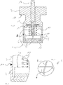
- Die Erfindung lässt zahlreiche Ausführungsformen zu. Einige davon sind nachfolgend anhand der Figuren näher erläutert werden. Gleiche Elemente sind in den Figuren mit gleichen Bezugszeichen versehen.
- Fig. 1
- zeigt einen erfindungsgemäßen Ultraschallwandler im Schnitt,
- Fig. 2
- zeigt einen Ausschnitt aus
Fig. 1 , - Fig. 3
- zeigt ein erfindungsgemäßes elektromechanisches Wandlerelement.
- Da das zweite Gehäuseteil 3 in einem unteren Bereich der Figur eine zu den Wänden des ersten Gehäuseteils 2 kongruente hülsenförmige Gestalt aufweist, um es mit diesem zu verbinden, aber in einem oberen Bereich konisch verjüngend ausgestaltet ist, wird das elektromechanische Wandlerelement 5 und gegebenenfalls das Koppelmittel vor der Verbindung von ersten und zweitem Gehäuseteil 2 und 3 eingebracht. Um diese jedoch bei der Verbindung nicht zu beschädigen, sind die Querschnittsfläche A einer Gehäusewand des ersten Gehäuseteils 2, der Abstand d der Verbindungsfläche von erstem und zweitem Gehäuseteil 2 zum Ultraschallfenster 4, also der Abstand der Schweißnaht 14 zum Ultraschallfenster 4, und der Werkstoff des ersten Gehäuseteils ausgewählt und aufeinander abgestimmt. Edelstahl als Werkstoff für das erste Gehäuseteil 2 weist typischerweise eine Wärmeleitfähigkeit von 10 bis 100 W/(m∗K) auf. Das zweite Gehäuseteil 3 besteht insbesondere aus demselben Werkstoff wie das erste Gehäuseteil 2. Verschweißt werden daher die beiden Gehäuseteile 2 und 3 insbesondere mittels Laser.
- Als Mittel zur Vorspannung 10 sind hier zwei Schraubendruckfedern 10 vorgesehen. Sie erzeugen vorgegebene Kräfte in Richtung des Ultraschallfensters 4 und leiten diese in das elektromechanische Wandlerelement 5 ein, wobei dieses dadurch gegen das Uttraschaitfenster 4 gedrückt gehalten wird. Gleichzeitig kontaktieren die Mittel zur Vorspannung 10 das elektromechanische Wandlerelement 5 elektrisch. Somit ist das Aufbringen einer oder mehrerer zusätzlicher Elektroden auf das elektromechanische Wandlerelement 5 überflüssig.
- Die zur Vorspannung geeigneten Mittel 10 kontaktieren eine zweite Oberfläche 7 des elektromechanischen Wandlerelements 5 galvanisch. Die erste Oberfläche 6 des elektromechanischen Wandlerelements 5 wird vom Ultraschallfenster 4 elektrisch kontaktiert. Das erste Gehäuseteil 2 ist dazu insbesondere aus einem elektrisch leitfähigen Material hergestellt. Um einen Kurzschluss zu vermeiden sind die Mittel zur Vorspannung 10 mit dem ersten Gehäuseteil 2 berührungsfrei gelagert. Hier stützen sie sich an einer Leitplatte 13 ab, welche auch als elektrischer Isolator dient. Über einen elektrischen Widerstand 12 wird der Stromkreis geschlossen. Hier weist der Ultraschallwandler 1 noch einen Stecker 16 in einer Bohrung im zweiten Gehäuseteil 3 auf, durch welchen die elektrische Kontaktierung und damit die Anregung durch und der Abgriff von den Spannungssignalen am elektromechanischen Wandlerelement 5 erfolgt. Elektrische Leitungen sind hier nicht näher gezeigt.
- Erfindungsgemäß ist die erste Oberfläche 6 des elektromechanischen Wandlerelements 5 eben und die zweite Oberfläche 7 ist in vier gleich große viertelkreisförmige Segmente 9 aufgeteilt. In einfacher Weise geschieht dies durch mehrere Schnitte 8 durch die zweite Oberfläche 7 des elektromechanischen Wandlerelements 5.
- Eine Anpassungsschicht 11 zur Anpassung der akustischen Impedanzen ist hier außerhalb des Gehäuses des Ultraschallwandlers 1 vorgesehen. Sie ist auf dem Ultraschallfenster 4 so angebracht, dass sich das Ultraschallfenster 4 zwischen der Anpassungsschicht 11 und dem elektromechanischen Wandlerelement 5 befindet. Die Anpassungsschicht 11 berührt somit das Fluid, dessen Durchfluss gemessen werden soll.
- In der gezeigten Ausführungsform weist der Ultraschallwandler 1 einen axialen Anschlag 17 im Bereich des zweiten Gehäuseteils 3 auf, welcher gegen einen axialen Anschlag eines dritten Gehäuseteils oder einer Rohrleitung vorspannbar ist, zum Einbau des Ultraschallwandlers 1 in eine Rohrleitung. Dieser axiale Anschlag 17 kann selbst als Dichtungsfläche ausgestaltet sein, oder eine Dichtung wird zwischen ihm und den axialen Anschlag des dritten Gehäuseteils oder der Rohrleitung angeordnet und vorgespannt.
- Zur Positionierung des elektromechanischen Wandlerelements 5 an einer vorbestimmten Position im Ultraschallwandler 1 während des Fertigungsprozesses, können hier nicht veranschaulichte Zentriernasen im ersten oder zweiten Gehäuseteil 2 oder 3 vorgesehen werden.
- Vorteilhaft ist zudem, eine glatte Oberfläche des Gehäuses des Ultraschallwandlers 1. So ist insbesondere die Schweißnaht nicht erhaben gegenüber der Mantelfläche des Gehäuses ausgeformt. Eine Funktion des Abstands jeder Schnittkante einer Außenkontur des Gehäuses zu einer Längsachse des Gehäuses ist somit vom Ultraschallfenster 4 bis zum axialen Anschlag 17 monoton, wobei die Schnittkante in einer Ebene liegt, in welcher die Längsachse des Gehäuses liegt.
-
- 1
- Ultraschallwandler
- 2
- Erstes Gehäuseteil
- 3
- Zweites Gehäuseteil
- 4
- Ultraschallfenster
- 5
- Elektromechanisches Wandlerelement
- 6
- Erste Oberfläche des elektromechanischen Wandlerelements
- 7
- Zweite Oberfläche des elektromechanischen Wandlerelements
- 8
- Schnitt im elektromechanischen Wandlerelement
- 9
- Segmente der ersten Oberfläche des elektromechanischen Wandlerelements
- 10
- Mittel zur Vorspannung
- 11
- Anpassungsschicht
- 12
- Widerstand
- 13
- Leiterplatte
- 14
- Schweißnaht
- 15
- Zentriernasen
- 16
- Stecker
- 17
- Axialer Anschlag
Claims (10)
- Ultraschallwandler für ein Ultraschall-Durchflussmessgerät, mit einem elektromechanischen Wandlerelement (5) und Mittel(10), die geeignet sind, das elektromechanische Wandlerelement (5) gegen das Ultraschallfenster (4) vorzuspannen, wobei eine erste Oberfläche (6) des elektromechanischen Wandlerelements (5) gegen das Ultraschallfenster (4) zeigt,
dadurch gekennzeichnet,
dass eine der ersten Oberfläche (6) gegenüberliegende zweite Oberfläche (7) des elektromechanischen Wandlerelements (5) in vier gleich große Segmente (9) durch tiefe Nuten unterteilt ist, welche mit den zur Vorspannung geeigneten Mitteln (10) galvanisch verbunden sind. - Ultraschallwandler nach Anspruch 1,
dadurch gekennzeichnet,
dass die zur Vorspannung geeigneten Mittel (10) eine Schraubendruckfeder umfassen, welche zur galvanischen Kontaktierung des elektromechanischen Wandlerelements (5) zumindest eine in einer Ebene verlaufende komplette Windung aufweist. - Ultraschallwandler nach einem der Ansprüche 1 oder 2,
dadurch gekennzeichnet,
dass zwischen dem elektromechanischen Wandlerelement (5) und dem Ultraschallfenster (4) ein Koppelmittel angeordnet ist. - Ultraschallwandler nach einem der Ansprüche 1 bis 3,
dadurch gekennzeichnet,
dass er eine Anpassungsschicht (11) aufweist, welche den Ultraschallwandler zur Umwelt hin begrenzt, wobei das Ultraschallfenster (4) zwischen dem elektromechanischen Wandlerelement (5) und der Anpassungsschicht (11) angeordnet ist. - Ultraschallwandler nach Anspruch 4,
dadurch gekennzeichnet,
dass die Anpassungsschicht (11) eine Verbundmatrix mit darin eingebetteten kugelförmigen Körpern umfasst. - Ultraschallwandler nach einem der Ansprüche 1 bis 5,
dadurch gekennzeichnet,
dass das Ultraschalifenster (4) die erste Oberfläche (6) des elektromechanischen Wandlerelements (5) galvanisch berührt, wobei das Ultraschallfenster (4) und die zur Vorspannung geeigneten Mittel (10) geeignet sind, eine Spannung am elektromechanischen Wandlerelement (5) anzulegen und/oder abzugreifen. - Ultraschallwandler nach Anspruch 6,
dadurch gekennzeichnet,
dass die zur Vorspannung geeigneten Mittel (10) mit dem Ultraschallfenster (4) galvanisch verbunden sind, wobei die galvanische Verbindung einen Widerstand von mindestens 50 Ω aufweist. - Ultraschallwandler nach einem der Ansprüche 1 bis 7,
dadurch gekennzeichnet,
dass er ein Gehäuse umfasst, weiches das elektromechanische Wandlerelement (5) umschließt, wobei das Gehäuse zum elektromechanischen Wandlerelement (5) weisende Nasen zur Zentrierung des elektromechanischen Wandlerelements (5) im Gehäuse aufweist. - Ultraschallwandler nach einem der Ansprüche 1 bis 8,
dadurch gekennzeichnet,
dass er ein Gehäuse umfasst, welches das elektromechanische Wandlerelement (5) umschließt, wobei das Gehäuse ein topfförmig ausgebildetes erstes Gehäuseteil (2) aufweist, dessen Boden das Ultraschallfenster (4) bildet, und, dass das Gehäuse ein zweites Gehäuseteil (3) aufweist mit einem axialen Anschlag zur Befestigung des Ultraschallwandlers an einem Messrohr, wobei eine Funktion des Abstands jeder Schnittkante einer Außenkontur des Gehäuses vom Ultraschallfenster bis zum axialen Anschlag zu einer Längsachse des Gehäuses monoton ist, wobei die Schnittkante in einer Ebene liegt, in welcher die Längsachse des Gehäuses liegt. - Ultraschallwandler nach Anspruch 9,
dadurch gekennzeichnet,
dass der erste Gehäuseteil (2) mit dem zweiten Gehäuseteil (3) stoffschlüssig verbunden ist.
Applications Claiming Priority (2)
| Application Number | Priority Date | Filing Date | Title |
|---|---|---|---|
| DE102011090079A DE102011090079A1 (de) | 2011-12-29 | 2011-12-29 | Ultraschallwandler für ein Ultraschall-Durchflussmessgerät |
| PCT/EP2012/073386 WO2013097992A1 (de) | 2011-12-29 | 2012-11-22 | Ultraschallwandler für ein ultraschall-durchflussmessgerät |
Publications (2)
| Publication Number | Publication Date |
|---|---|
| EP2798316A1 EP2798316A1 (de) | 2014-11-05 |
| EP2798316B1 true EP2798316B1 (de) | 2019-11-06 |
Family
ID=47324100
Family Applications (1)
| Application Number | Title | Priority Date | Filing Date |
|---|---|---|---|
| EP12798231.2A Active EP2798316B1 (de) | 2011-12-29 | 2012-11-22 | Ultraschallwandler für ein ultraschall-durchflussmessgerät |
Country Status (4)
| Country | Link |
|---|---|
| US (1) | US9200946B2 (de) |
| EP (1) | EP2798316B1 (de) |
| DE (1) | DE102011090079A1 (de) |
| WO (1) | WO2013097992A1 (de) |
Families Citing this family (12)
| Publication number | Priority date | Publication date | Assignee | Title |
|---|---|---|---|---|
| DE102011090080B4 (de) * | 2011-12-29 | 2023-02-02 | Endress + Hauser Flowtec Ag | Austauschbarer Ultraschallwandler für ein Ultraschall-Durchflussmessgerät |
| RU2582889C1 (ru) * | 2014-12-11 | 2016-04-27 | Общество с ограниченной ответственностью "Татинтек" | Ультразвуковой пьезоэлектрический преобразователь |
| DE102016101154B4 (de) | 2016-01-22 | 2024-03-14 | Krohne Ag | Ultraschallwandler |
| WO2018019974A1 (en) * | 2016-07-29 | 2018-02-01 | Koninklijke Philips N.V. | Ultrasound probe with thermal and drop impact management |
| US10002870B2 (en) | 2016-08-16 | 2018-06-19 | Texas Instruments Incorporated | Process enhancement using double sided epitaxial on substrate |
| DE102017214370A1 (de) * | 2017-08-17 | 2019-02-21 | Landis + Gyr Gmbh | Schallkopf für einen Durchflussmesser mit gestufter Seitenwand |
| DE102017214374A1 (de) * | 2017-08-17 | 2019-02-21 | Landis + Gyr Gmbh | Schallkopf für einen Durchflussmesser mit Verstärkungsblech |
| DE102017214373A1 (de) * | 2017-08-17 | 2019-02-21 | Landis + Gyr Gmbh | Schallkopf für einen Durchflussmesser mit Ausziehmitteln |
| DE102017214371A1 (de) * | 2017-08-17 | 2019-02-21 | Landis + Gyr Gmbh | Schallkopf für einen Durchflussmesser mit elektrisch isolierender Verklebung |
| GB2573305A (en) * | 2018-05-01 | 2019-11-06 | Tribosonics Ltd | An ultrasonic transducer |
| US11806749B2 (en) * | 2021-10-28 | 2023-11-07 | Baker Hughes, A Ge Company, Llc | Ultrasonic transducer for flow measurement |
| DE102022107092B4 (de) * | 2022-03-25 | 2023-12-07 | Krohne Ag | Ultraschallwandler |
Family Cites Families (23)
| Publication number | Priority date | Publication date | Assignee | Title |
|---|---|---|---|---|
| US3059130A (en) * | 1957-10-03 | 1962-10-16 | United Insulator Company Ltd | Electromechanical transducers |
| US3036231A (en) * | 1958-07-24 | 1962-05-22 | Sperry Prod Inc | High resolution piezoelectric transducer |
| US3960018A (en) | 1973-07-23 | 1976-06-01 | Pcb Piezotronics, Inc. | Conformal pressure transducer |
| US3925692A (en) * | 1974-06-13 | 1975-12-09 | Westinghouse Electric Corp | Replaceable element ultrasonic flowmeter transducer |
| US4156158A (en) * | 1977-08-17 | 1979-05-22 | Westinghouse Electric Corp. | Double serrated piezoelectric transducer |
| US4297607A (en) * | 1980-04-25 | 1981-10-27 | Panametrics, Inc. | Sealed, matched piezoelectric transducer |
| US4746831A (en) * | 1985-03-27 | 1988-05-24 | Kaijo Denki Co., Ltd. | Ultrasonic transreceiver |
| US4742717A (en) * | 1986-09-16 | 1988-05-10 | Kaijo Denki Co., Ltd. | Gas flow rate measuring device |
| CH672386A5 (de) | 1986-11-03 | 1989-11-15 | Olten Ag Elektro Apparatebau | |
| SE455886B (sv) * | 1986-12-15 | 1988-08-15 | Asea Ab | Magnetoelastisk kraftgivare |
| DE4443415A1 (de) | 1994-12-06 | 1996-06-13 | Siemens Ag | Vorrichtung zur Aufnahme eines Schallwandlers und Ultraschall-Durchflußmesser mit derselben |
| EP0766071B1 (de) | 1995-09-28 | 2002-04-10 | Endress + Hauser Gmbh + Co. | Ultraschallwandler |
| CN1104629C (zh) | 1995-12-13 | 2003-04-02 | 松下电器产业株式会社 | 超声波流量计和超声波收发器 |
| US5886456A (en) * | 1996-08-29 | 1999-03-23 | The University Of Dayton | Ultrasonic transducer and ultrasonic detection and high temperature processing systems incorporating same |
| AT6511U3 (de) * | 2003-07-16 | 2004-09-27 | Avl List Gmbh | Ultraschall-gasdurchflusssensor sowie vorrichtung zur messung von abgas-strömungen von verbrennungskraftmaschinen sowie ein verfahren zur ermittlung des durchflusses von gasen |
| JPWO2005029912A1 (ja) * | 2003-09-18 | 2006-11-30 | 松下電器産業株式会社 | 超音波振動子を用いた超音波流量計 |
| DE102005003398A1 (de) * | 2005-01-24 | 2006-08-03 | Endress + Hauser Flowtec Ag | Vorrichtung zur Bestimmung und/oder Überwachung des Volumen- und/oder Massendurchflusses |
| DE102006062706B4 (de) * | 2006-03-30 | 2012-12-06 | Krohne Ag | Ultraschalldurchflußmeßgerät |
| JP4857296B2 (ja) | 2008-03-07 | 2012-01-18 | パナソニック株式会社 | 音響整合体 |
| DE102009032809B4 (de) | 2008-07-15 | 2019-04-11 | Krohne Ag | Ultraschallwandler |
| US7669483B1 (en) * | 2009-02-27 | 2010-03-02 | Murray F Feller | Flowmeter transducer clamping |
| DE102009027355A1 (de) | 2009-06-30 | 2011-01-05 | Endress + Hauser Flowtec Ag | Ultraschallsensor und Ultraschall-Durchflussmessgerät |
| US8544343B2 (en) | 2010-11-19 | 2013-10-01 | Cameron International Corporation | Chordal gas flowmeter with transducers installed outside the pressure boundary |
-
2011
- 2011-12-29 DE DE102011090079A patent/DE102011090079A1/de not_active Withdrawn
-
2012
- 2012-11-22 EP EP12798231.2A patent/EP2798316B1/de active Active
- 2012-11-22 WO PCT/EP2012/073386 patent/WO2013097992A1/de not_active Ceased
- 2012-12-26 US US13/726,759 patent/US9200946B2/en active Active
Non-Patent Citations (1)
| Title |
|---|
| None * |
Also Published As
| Publication number | Publication date |
|---|---|
| DE102011090079A1 (de) | 2013-07-04 |
| US20130205904A1 (en) | 2013-08-15 |
| WO2013097992A1 (de) | 2013-07-04 |
| EP2798316A1 (de) | 2014-11-05 |
| US9200946B2 (en) | 2015-12-01 |
Similar Documents
| Publication | Publication Date | Title |
|---|---|---|
| EP2798316A1 (de) | Ultraschallwandler für ein ultraschall-durchflussmessgerät | |
| WO2013097994A1 (de) | Ultraschallwandler für ein durchflussmessgerät | |
| WO2013097993A1 (de) | Austauschbarer ultraschallwandler für ein ultraschall-durchflussmessgerät | |
| DE102014101372B4 (de) | Vibrationssensor mit geklebtem Antrieb | |
| EP2992302B1 (de) | Ultraschallwandler und ultraschall-durchflussmessgerät | |
| EP3746749B1 (de) | Ultraschallwandler mit einer piezokeramik und verfahren zur herstellung eines solchen ultraschallwandlers | |
| DE102013212331A1 (de) | Verfahren zum Verbinden eines Rohrkabelschuhs mit einer aus Aluminium hergestellten Litze | |
| DE102007057386A1 (de) | Baugruppe und elektrochemischer Sensor mit einer solchen Baugruppe, insbesondere Leitfähigkeitssensor | |
| DE29611678U1 (de) | Schallwandler, insbesondere Ultraschallwandler | |
| WO2018219613A1 (de) | Ultraschallwandler | |
| EP2449552B1 (de) | Ultraschall-durchflussmessgerät | |
| WO2014177411A1 (de) | Ultraschallwandler und ultraschall-durchflussmessgerät | |
| EP2496937A1 (de) | Kopplungselement zur akustischen ankopplung eines schallwandlers an einen körper sowie schallwandler umfassend ein derartiges kopplungselement | |
| DE102013114428A1 (de) | Messrohr für ein magnetisch-induktives Durchflussmessgerät und Magnetisch-induktives Durchflussmessgerät | |
| DE102009046886A1 (de) | Messgerät | |
| EP4056960B1 (de) | Ultraschallwandler zum senden und/oder empfangen von ultraschallwellen | |
| DE29509574U1 (de) | Schallwandler | |
| DE102007039016A1 (de) | Koppelelement für ein Ultraschall-Durchflussmessgerät | |
| EP3084360A1 (de) | Messrohr für ein magnetisch-induktives durchflussmessgerät | |
| DE10201873A1 (de) | Ultraschallwandler-Einrichtung mit Elektroden aus elektrisch leitenden Kunststoffen | |
| EP1358476B1 (de) | Ultraschall-sensor für die prozesssteuerung beim widerstandspunktschweissen | |
| EP1462204B1 (de) | Elektrodenhalterung für eine Widerstandsschweissmaschine mit integrietem Ultraschallsensor | |
| EP1902789B1 (de) | Ultraschallwandler und Ultraschallsensor | |
| WO2001011353A2 (de) | Ultraschall-sensoranordnung | |
| DE202011101455U1 (de) | Messrohr für einen Ultraschall-Durchflussmesser und Ultraschall-Durchflussmesser |
Legal Events
| Date | Code | Title | Description |
|---|---|---|---|
| PUAI | Public reference made under article 153(3) epc to a published international application that has entered the european phase |
Free format text: ORIGINAL CODE: 0009012 |
|
| 17P | Request for examination filed |
Effective date: 20140602 |
|
| AK | Designated contracting states |
Kind code of ref document: A1 Designated state(s): AL AT BE BG CH CY CZ DE DK EE ES FI FR GB GR HR HU IE IS IT LI LT LU LV MC MK MT NL NO PL PT RO RS SE SI SK SM TR |
|
| DAX | Request for extension of the european patent (deleted) | ||
| STAA | Information on the status of an ep patent application or granted ep patent |
Free format text: STATUS: EXAMINATION IS IN PROGRESS |
|
| 17Q | First examination report despatched |
Effective date: 20181212 |
|
| GRAP | Despatch of communication of intention to grant a patent |
Free format text: ORIGINAL CODE: EPIDOSNIGR1 |
|
| STAA | Information on the status of an ep patent application or granted ep patent |
Free format text: STATUS: GRANT OF PATENT IS INTENDED |
|
| INTG | Intention to grant announced |
Effective date: 20190726 |
|
| RIN1 | Information on inventor provided before grant (corrected) |
Inventor name: UEBERSCHLAG, PIERRE Inventor name: BERGER, ANDREAS Inventor name: BEZDEK, MICHAL |
|
| GRAS | Grant fee paid |
Free format text: ORIGINAL CODE: EPIDOSNIGR3 |
|
| GRAA | (expected) grant |
Free format text: ORIGINAL CODE: 0009210 |
|
| STAA | Information on the status of an ep patent application or granted ep patent |
Free format text: STATUS: THE PATENT HAS BEEN GRANTED |
|
| AK | Designated contracting states |
Kind code of ref document: B1 Designated state(s): AL AT BE BG CH CY CZ DE DK EE ES FI FR GB GR HR HU IE IS IT LI LT LU LV MC MK MT NL NO PL PT RO RS SE SI SK SM TR |
|
| REG | Reference to a national code |
Ref country code: GB Ref legal event code: FG4D Free format text: NOT ENGLISH |
|
| REG | Reference to a national code |
Ref country code: CH Ref legal event code: EP Ref country code: AT Ref legal event code: REF Ref document number: 1199369 Country of ref document: AT Kind code of ref document: T Effective date: 20191115 |
|
| REG | Reference to a national code |
Ref country code: IE Ref legal event code: FG4D Free format text: LANGUAGE OF EP DOCUMENT: GERMAN |
|
| REG | Reference to a national code |
Ref country code: DE Ref legal event code: R096 Ref document number: 502012015503 Country of ref document: DE |
|
| REG | Reference to a national code |
Ref country code: LT Ref legal event code: MG4D |
|
| PG25 | Lapsed in a contracting state [announced via postgrant information from national office to epo] |
Ref country code: ES Free format text: LAPSE BECAUSE OF FAILURE TO SUBMIT A TRANSLATION OF THE DESCRIPTION OR TO PAY THE FEE WITHIN THE PRESCRIBED TIME-LIMIT Effective date: 20191106 Ref country code: LV Free format text: LAPSE BECAUSE OF FAILURE TO SUBMIT A TRANSLATION OF THE DESCRIPTION OR TO PAY THE FEE WITHIN THE PRESCRIBED TIME-LIMIT Effective date: 20191106 Ref country code: SE Free format text: LAPSE BECAUSE OF FAILURE TO SUBMIT A TRANSLATION OF THE DESCRIPTION OR TO PAY THE FEE WITHIN THE PRESCRIBED TIME-LIMIT Effective date: 20191106 Ref country code: LT Free format text: LAPSE BECAUSE OF FAILURE TO SUBMIT A TRANSLATION OF THE DESCRIPTION OR TO PAY THE FEE WITHIN THE PRESCRIBED TIME-LIMIT Effective date: 20191106 Ref country code: FI Free format text: LAPSE BECAUSE OF FAILURE TO SUBMIT A TRANSLATION OF THE DESCRIPTION OR TO PAY THE FEE WITHIN THE PRESCRIBED TIME-LIMIT Effective date: 20191106 Ref country code: BG Free format text: LAPSE BECAUSE OF FAILURE TO SUBMIT A TRANSLATION OF THE DESCRIPTION OR TO PAY THE FEE WITHIN THE PRESCRIBED TIME-LIMIT Effective date: 20200206 Ref country code: PL Free format text: LAPSE BECAUSE OF FAILURE TO SUBMIT A TRANSLATION OF THE DESCRIPTION OR TO PAY THE FEE WITHIN THE PRESCRIBED TIME-LIMIT Effective date: 20191106 Ref country code: NO Free format text: LAPSE BECAUSE OF FAILURE TO SUBMIT A TRANSLATION OF THE DESCRIPTION OR TO PAY THE FEE WITHIN THE PRESCRIBED TIME-LIMIT Effective date: 20200206 Ref country code: GR Free format text: LAPSE BECAUSE OF FAILURE TO SUBMIT A TRANSLATION OF THE DESCRIPTION OR TO PAY THE FEE WITHIN THE PRESCRIBED TIME-LIMIT Effective date: 20200207 Ref country code: PT Free format text: LAPSE BECAUSE OF FAILURE TO SUBMIT A TRANSLATION OF THE DESCRIPTION OR TO PAY THE FEE WITHIN THE PRESCRIBED TIME-LIMIT Effective date: 20200306 |
|
| REG | Reference to a national code |
Ref country code: NL Ref legal event code: FP |
|
| PG25 | Lapsed in a contracting state [announced via postgrant information from national office to epo] |
Ref country code: HR Free format text: LAPSE BECAUSE OF FAILURE TO SUBMIT A TRANSLATION OF THE DESCRIPTION OR TO PAY THE FEE WITHIN THE PRESCRIBED TIME-LIMIT Effective date: 20191106 Ref country code: RS Free format text: LAPSE BECAUSE OF FAILURE TO SUBMIT A TRANSLATION OF THE DESCRIPTION OR TO PAY THE FEE WITHIN THE PRESCRIBED TIME-LIMIT Effective date: 20191106 Ref country code: IS Free format text: LAPSE BECAUSE OF FAILURE TO SUBMIT A TRANSLATION OF THE DESCRIPTION OR TO PAY THE FEE WITHIN THE PRESCRIBED TIME-LIMIT Effective date: 20200306 |
|
| PG25 | Lapsed in a contracting state [announced via postgrant information from national office to epo] |
Ref country code: AL Free format text: LAPSE BECAUSE OF FAILURE TO SUBMIT A TRANSLATION OF THE DESCRIPTION OR TO PAY THE FEE WITHIN THE PRESCRIBED TIME-LIMIT Effective date: 20191106 |
|
| REG | Reference to a national code |
Ref country code: CH Ref legal event code: PL |
|
| PG25 | Lapsed in a contracting state [announced via postgrant information from national office to epo] |
Ref country code: CZ Free format text: LAPSE BECAUSE OF FAILURE TO SUBMIT A TRANSLATION OF THE DESCRIPTION OR TO PAY THE FEE WITHIN THE PRESCRIBED TIME-LIMIT Effective date: 20191106 Ref country code: RO Free format text: LAPSE BECAUSE OF FAILURE TO SUBMIT A TRANSLATION OF THE DESCRIPTION OR TO PAY THE FEE WITHIN THE PRESCRIBED TIME-LIMIT Effective date: 20191106 Ref country code: LI Free format text: LAPSE BECAUSE OF NON-PAYMENT OF DUE FEES Effective date: 20191130 Ref country code: CH Free format text: LAPSE BECAUSE OF NON-PAYMENT OF DUE FEES Effective date: 20191130 Ref country code: EE Free format text: LAPSE BECAUSE OF FAILURE TO SUBMIT A TRANSLATION OF THE DESCRIPTION OR TO PAY THE FEE WITHIN THE PRESCRIBED TIME-LIMIT Effective date: 20191106 Ref country code: LU Free format text: LAPSE BECAUSE OF NON-PAYMENT OF DUE FEES Effective date: 20191122 Ref country code: DK Free format text: LAPSE BECAUSE OF FAILURE TO SUBMIT A TRANSLATION OF THE DESCRIPTION OR TO PAY THE FEE WITHIN THE PRESCRIBED TIME-LIMIT Effective date: 20191106 |
|
| REG | Reference to a national code |
Ref country code: DE Ref legal event code: R097 Ref document number: 502012015503 Country of ref document: DE |
|
| REG | Reference to a national code |
Ref country code: BE Ref legal event code: MM Effective date: 20191130 |
|
| PG25 | Lapsed in a contracting state [announced via postgrant information from national office to epo] |
Ref country code: SK Free format text: LAPSE BECAUSE OF FAILURE TO SUBMIT A TRANSLATION OF THE DESCRIPTION OR TO PAY THE FEE WITHIN THE PRESCRIBED TIME-LIMIT Effective date: 20191106 Ref country code: MC Free format text: LAPSE BECAUSE OF FAILURE TO SUBMIT A TRANSLATION OF THE DESCRIPTION OR TO PAY THE FEE WITHIN THE PRESCRIBED TIME-LIMIT Effective date: 20191106 Ref country code: SM Free format text: LAPSE BECAUSE OF FAILURE TO SUBMIT A TRANSLATION OF THE DESCRIPTION OR TO PAY THE FEE WITHIN THE PRESCRIBED TIME-LIMIT Effective date: 20191106 |
|
| PLBE | No opposition filed within time limit |
Free format text: ORIGINAL CODE: 0009261 |
|
| STAA | Information on the status of an ep patent application or granted ep patent |
Free format text: STATUS: NO OPPOSITION FILED WITHIN TIME LIMIT |
|
| 26N | No opposition filed |
Effective date: 20200807 |
|
| PG25 | Lapsed in a contracting state [announced via postgrant information from national office to epo] |
Ref country code: IE Free format text: LAPSE BECAUSE OF NON-PAYMENT OF DUE FEES Effective date: 20191122 |
|
| PG25 | Lapsed in a contracting state [announced via postgrant information from national office to epo] |
Ref country code: BE Free format text: LAPSE BECAUSE OF NON-PAYMENT OF DUE FEES Effective date: 20191130 Ref country code: SI Free format text: LAPSE BECAUSE OF FAILURE TO SUBMIT A TRANSLATION OF THE DESCRIPTION OR TO PAY THE FEE WITHIN THE PRESCRIBED TIME-LIMIT Effective date: 20191106 |
|
| REG | Reference to a national code |
Ref country code: AT Ref legal event code: MM01 Ref document number: 1199369 Country of ref document: AT Kind code of ref document: T Effective date: 20191122 |
|
| PG25 | Lapsed in a contracting state [announced via postgrant information from national office to epo] |
Ref country code: AT Free format text: LAPSE BECAUSE OF NON-PAYMENT OF DUE FEES Effective date: 20191122 Ref country code: IT Free format text: LAPSE BECAUSE OF FAILURE TO SUBMIT A TRANSLATION OF THE DESCRIPTION OR TO PAY THE FEE WITHIN THE PRESCRIBED TIME-LIMIT Effective date: 20191106 |
|
| PG25 | Lapsed in a contracting state [announced via postgrant information from national office to epo] |
Ref country code: CY Free format text: LAPSE BECAUSE OF FAILURE TO SUBMIT A TRANSLATION OF THE DESCRIPTION OR TO PAY THE FEE WITHIN THE PRESCRIBED TIME-LIMIT Effective date: 20191106 |
|
| PG25 | Lapsed in a contracting state [announced via postgrant information from national office to epo] |
Ref country code: MT Free format text: LAPSE BECAUSE OF FAILURE TO SUBMIT A TRANSLATION OF THE DESCRIPTION OR TO PAY THE FEE WITHIN THE PRESCRIBED TIME-LIMIT Effective date: 20191106 Ref country code: HU Free format text: LAPSE BECAUSE OF FAILURE TO SUBMIT A TRANSLATION OF THE DESCRIPTION OR TO PAY THE FEE WITHIN THE PRESCRIBED TIME-LIMIT; INVALID AB INITIO Effective date: 20121122 |
|
| PG25 | Lapsed in a contracting state [announced via postgrant information from national office to epo] |
Ref country code: TR Free format text: LAPSE BECAUSE OF FAILURE TO SUBMIT A TRANSLATION OF THE DESCRIPTION OR TO PAY THE FEE WITHIN THE PRESCRIBED TIME-LIMIT Effective date: 20191106 |
|
| PG25 | Lapsed in a contracting state [announced via postgrant information from national office to epo] |
Ref country code: MK Free format text: LAPSE BECAUSE OF FAILURE TO SUBMIT A TRANSLATION OF THE DESCRIPTION OR TO PAY THE FEE WITHIN THE PRESCRIBED TIME-LIMIT Effective date: 20191106 |
|
| P01 | Opt-out of the competence of the unified patent court (upc) registered |
Effective date: 20230601 |
|
| PGFP | Annual fee paid to national office [announced via postgrant information from national office to epo] |
Ref country code: GB Payment date: 20231123 Year of fee payment: 12 |
|
| GBPC | Gb: european patent ceased through non-payment of renewal fee |
Effective date: 20241122 |
|
| PG25 | Lapsed in a contracting state [announced via postgrant information from national office to epo] |
Ref country code: GB Free format text: LAPSE BECAUSE OF NON-PAYMENT OF DUE FEES Effective date: 20241122 |
|
| PGFP | Annual fee paid to national office [announced via postgrant information from national office to epo] |
Ref country code: NL Payment date: 20251119 Year of fee payment: 14 |
|
| PGFP | Annual fee paid to national office [announced via postgrant information from national office to epo] |
Ref country code: DE Payment date: 20251119 Year of fee payment: 14 |
|
| PGFP | Annual fee paid to national office [announced via postgrant information from national office to epo] |
Ref country code: FR Payment date: 20251125 Year of fee payment: 14 |