EP2798242B1 - Getriebegehäuse, getriebeeinheit mit einem solchen getriebegehäuse und getriebemotor mit einer solchen getriebeeinheit - Google Patents
Getriebegehäuse, getriebeeinheit mit einem solchen getriebegehäuse und getriebemotor mit einer solchen getriebeeinheit Download PDFInfo
- Publication number
- EP2798242B1 EP2798242B1 EP13702363.6A EP13702363A EP2798242B1 EP 2798242 B1 EP2798242 B1 EP 2798242B1 EP 13702363 A EP13702363 A EP 13702363A EP 2798242 B1 EP2798242 B1 EP 2798242B1
- Authority
- EP
- European Patent Office
- Prior art keywords
- housing
- bores
- group
- bore
- gearbox
- Prior art date
- Legal status (The legal status is an assumption and is not a legal conclusion. Google has not performed a legal analysis and makes no representation as to the accuracy of the status listed.)
- Revoked
Links
Images



Classifications
-
- F—MECHANICAL ENGINEERING; LIGHTING; HEATING; WEAPONS; BLASTING
- F16—ENGINEERING ELEMENTS AND UNITS; GENERAL MEASURES FOR PRODUCING AND MAINTAINING EFFECTIVE FUNCTIONING OF MACHINES OR INSTALLATIONS; THERMAL INSULATION IN GENERAL
- F16H—GEARING
- F16H57/00—General details of gearing
- F16H57/02—Gearboxes; Mounting gearing therein
-
- F—MECHANICAL ENGINEERING; LIGHTING; HEATING; WEAPONS; BLASTING
- F16—ENGINEERING ELEMENTS AND UNITS; GENERAL MEASURES FOR PRODUCING AND MAINTAINING EFFECTIVE FUNCTIONING OF MACHINES OR INSTALLATIONS; THERMAL INSULATION IN GENERAL
- F16H—GEARING
- F16H57/00—General details of gearing
- F16H57/02—Gearboxes; Mounting gearing therein
- F16H57/027—Gearboxes; Mounting gearing therein characterised by means for venting gearboxes, e.g. air breathers
-
- F—MECHANICAL ENGINEERING; LIGHTING; HEATING; WEAPONS; BLASTING
- F16—ENGINEERING ELEMENTS AND UNITS; GENERAL MEASURES FOR PRODUCING AND MAINTAINING EFFECTIVE FUNCTIONING OF MACHINES OR INSTALLATIONS; THERMAL INSULATION IN GENERAL
- F16H—GEARING
- F16H57/00—General details of gearing
- F16H57/04—Features relating to lubrication or cooling or heating
- F16H57/0408—Exchange, draining or filling of transmission lubricant
-
- F—MECHANICAL ENGINEERING; LIGHTING; HEATING; WEAPONS; BLASTING
- F16—ENGINEERING ELEMENTS AND UNITS; GENERAL MEASURES FOR PRODUCING AND MAINTAINING EFFECTIVE FUNCTIONING OF MACHINES OR INSTALLATIONS; THERMAL INSULATION IN GENERAL
- F16H—GEARING
- F16H57/00—General details of gearing
- F16H57/04—Features relating to lubrication or cooling or heating
- F16H57/0447—Control of lubricant levels, e.g. lubricant level control dependent on temperature
-
- F—MECHANICAL ENGINEERING; LIGHTING; HEATING; WEAPONS; BLASTING
- F16—ENGINEERING ELEMENTS AND UNITS; GENERAL MEASURES FOR PRODUCING AND MAINTAINING EFFECTIVE FUNCTIONING OF MACHINES OR INSTALLATIONS; THERMAL INSULATION IN GENERAL
- F16H—GEARING
- F16H57/00—General details of gearing
- F16H57/04—Features relating to lubrication or cooling or heating
- F16H57/0447—Control of lubricant levels, e.g. lubricant level control dependent on temperature
- F16H57/0449—Sensors or indicators for controlling the fluid level
-
- F—MECHANICAL ENGINEERING; LIGHTING; HEATING; WEAPONS; BLASTING
- F16—ENGINEERING ELEMENTS AND UNITS; GENERAL MEASURES FOR PRODUCING AND MAINTAINING EFFECTIVE FUNCTIONING OF MACHINES OR INSTALLATIONS; THERMAL INSULATION IN GENERAL
- F16H—GEARING
- F16H57/00—General details of gearing
- F16H57/02—Gearboxes; Mounting gearing therein
- F16H57/031—Gearboxes; Mounting gearing therein characterised by covers or lids for gearboxes
-
- Y—GENERAL TAGGING OF NEW TECHNOLOGICAL DEVELOPMENTS; GENERAL TAGGING OF CROSS-SECTIONAL TECHNOLOGIES SPANNING OVER SEVERAL SECTIONS OF THE IPC; TECHNICAL SUBJECTS COVERED BY FORMER USPC CROSS-REFERENCE ART COLLECTIONS [XRACs] AND DIGESTS
- Y10—TECHNICAL SUBJECTS COVERED BY FORMER USPC
- Y10T—TECHNICAL SUBJECTS COVERED BY FORMER US CLASSIFICATION
- Y10T74/00—Machine element or mechanism
- Y10T74/21—Elements
- Y10T74/2186—Gear casings
Definitions
- the invention relates to a transmission housing having a housing body, which encloses a housing interior and having a passage opening for a shaft which is surrounded by a connection surface, wherein in the housing body a plurality of GeHouse stresses passing through holes are formed, which serve to fill oil in the housing interior or to drain from this, to detect the oil level in the housing interior and to vent the housing interior. Furthermore, the invention relates to a transmission unit and a geared motor, which are provided with such a transmission housing.
- Geared motors are known in various embodiments and form a combination of a motor, typically an electric motor, and a reduction gear that causes the output shaft of the gearbox to rotate at a slower speed but at a much higher torque than that of the motor.
- a motor typically an electric motor
- a reduction gear that causes the output shaft of the gearbox to rotate at a slower speed but at a much higher torque than that of the motor.
- so-called MOTOX standard geared motors are available, which are available for the power range up to 200kW and a gear torque up to 20,000Nm with helical, bevel and helical bevel gearboxes.
- geared motors with planetary gear are available.
- Geared motors are used in engineering, for example, as actuators for motors, feed drives on machines and drives for robots, windscreen wipers, etc.
- the gear housing is provided with a connection surface, usually a standard flange, via which it can be connected to the driven shaft.
- the gear units of the geared motors must be lubricated during operation.
- the interior of the gear housing filled with oil to a predetermined degree.
- bores are provided in the housing wall of the transmission housing, which in operation function as an oil filler opening, oil drain opening, vent opening and as an opening for measuring the fill level in the transmission housing.
- the holes are provided in such a number and positioned so that the above functions are fulfilled even in different mounting positions.
- this sometimes requires an elaborate processing, since the transmission housing must be re-clamped and positioned several times to introduce the holes.
- Object of the present invention is therefore to provide a gear housing and a gear unit and a geared motor, which can be produced in a simple manner.
- the holes are introduced from two processing sides forth in the housing body, wherein a first group of at least two holes from a housing side around the terminal surface distributed in the housing body is introduced and a second group with the remaining holes of a second housing side adjacent to the first housing side is inserted into the housing body.
- the invention is based on the consideration, the holes which are provided during operation as oil filler, oil drain, vent and opening for measuring the level to position such that they can be introduced from two adjacent sides of the housing in the housing body.
- the holes which are provided during operation as oil filler, oil drain, vent and opening for measuring the level to position such that they can be introduced from two adjacent sides of the housing in the housing body.
- the bores of the first group are parallel to each other and perpendicular to the plane passing through the connection surface is stretched, run. Due to their parallel orientation, the holes can be made in one operation, and by aligning with the pad, the holes of the first group and the pad can be made without re-adjusting the machine between operations.
- the holes of the second group parallel to each other, and then they are expediently aligned parallel to the plane of the pad and thus perpendicular to the holes of the first group, so that the machining planes for the two groups of holes perpendicular to each other, and also the pad is parallel to the one and perpendicular to the other working plane, whereby the processing is further simplified.
- the first group of holes comprises a total of two holes and the second group of holes a total of three holes, wherein the two holes of the first group are positioned so that the first hole for draining oil and the second bore is used to measure the oil level, when the gear housing is oriented such that the pad faces to the side and the holes of the second group are directed upward.
- oil can be drained from the housing interior via the holes of the first group and the oil level can be measured.
- the upwardly facing holes of the second group can be partially used to fill oil in the housing interior or to vent this.
- the holes of the first group are positioned such that the first bore of the vent and the filling and the second bore of the measurement of the oil level is used when the gear housing is oriented such that the pad faces to the side and the holes of the second group after are directed down.
- the first hole of the first group has the dual function, the Fill and vent the gearbox with oil while the second hole is used to measure the oil level.
- the downwardly directed holes of the second group may optionally be used to drain oil from the transmission housing.
- the two holes of the first group may be positioned such that the first bore is for draining oil and the second bore for bleeding and filling when the transmission housing is oriented such that the pad faces to the side and the bores of the second group to the side.
- the oil level can be recorded via the respective upper hole of the second group.
- the holes of the first group are preferably positioned on the outer edge of the housing interior, wherein the first bore with respect to the center of the passage opening for the transmission output shaft about a 7 o'clock position and the second bore about one 4 o'clock position when the pad faces to the side and the holes in the second group are facing up.
- the bores of the second group are positioned according to an embodiment of the present invention such that, with the connection surface facing upwards, a first bore serves for draining oil and a second bore for measuring the oil level and, when the connection surface is downwards, the first and / or the second Bore venting and filling and the third bore located between the first and second bores to measure the oil level.
- the holes of the first group are used for filling and bleeding or draining oil.
- the three holes of the second group are arranged in the form of a triangle, wherein the first bore of the second group at the far from the pad lying end portion of the housing side, in which it is placed, is disposed, the second bore on the terminal surface facing the end face of the housing side and the third bore in Gereteachscardi between the first and the second bore, but laterally spaced from them is positioned.
- a transmission unit 1 which is part of a geared motor not shown.
- the transmission unit 1 comprises a transmission housing 2 with a housing body 3, which encloses an interior, in which a transmission is housed.
- a transmission is housed.
- the axis X of the output shaft 4 also represents the transmission axis X.
- the gear housing 2 also carries a connecting flange 5, via which the unit to be driven can be attached to the gear unit 1.
- the output shaft 4 and the connecting flange 5 opposite a through hole 6 is provided in the transmission housing 2, which is penetrated by an output or output shaft of a motor unit, not shown.
- the passage opening 6 is surrounded by a connection surface 7, via which the motor unit can be connected to the transmission unit 1.
- the transmission of the transmission unit 1 must be lubricated during operation.
- the interior of the gear housing 2 and the housing body 3 is filled with oil.
- a plurality of the Gezzawandung passing through holes 8, 9, 10, 11, 12 are formed in the housing body 3, which in operation as an oil filler opening, oil drain opening, vent and as an opening for measuring the oil level in the transmission housing 2 act.
- the holes 8 to 12 are provided in such a number and positioned so that the above functions are fulfilled in different mounting positions.
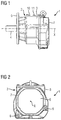
- the bores 8 to 12 of two processing sides are introduced into the housing body 3, wherein a first group consisting of two holes 8, 9 on that side of the housing, on which the connection surface 7 is provided in the housing body 3 and a second group with the remaining three holes 10, 11, 12 at an adjacent, in the Figures 1 and 2 overhead housing side are provided in the housing body 3.
- the two holes 8, 9 of the first group are aligned perpendicular to a plane spanned by the terminal surface 7.
- the housing side, in which the bores 10, 11, 12 of the second group are provided, is perpendicular to the connection surface 7, and the bores 10, 11, 12 of the second group are introduced into the housing body 3 perpendicular to this side of the housing and extend through a mounting lid 3a mounted on the case body 3.
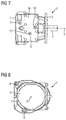
- the FIG. 2 indicates that the first group of holes 8, 9 arranged distributed around the terminal surface 7 and positioned at the outer edge region of the housing body 3, so that the holes 8, 9 open into the housing interior at its outer edge.
- the first hole 8 in the FIG. 2 Positioned at the bottom left so that it assumes about a 7 o'clock position relative to the transmission axis X, and the second bore is positioned approximately at the 4 o'clock position relative to the transmission axis X.
- the bores 10, 11, 12 of the second group are positioned in the manner of a triangle, wherein the first bore 10 is located on the lying remote from the terminal surface 7 end portion of the housing side, in which it is incorporated, the second Bore 11 is disposed on the terminal surface 7 facing end portion of the housing side and the third bore 12 in the transmission axis between the first and second holes 10, 11, but laterally spaced therefrom is positioned.
- the first bore 8 of the first group serves as an oil drain opening and the second bore 9 to the level in the To measure transmission housing 2.
- the bores 10, 11, 12 of the second group can optionally be used to fill in the transmission housing 2 oil or to vent the transmission housing 2.
- the first bore 8 of the first group is used to fill and bleed the gear housing 2 and the second bore 9 for measuring the oil level.
- the holes 10, 11, 12 of the second group can optionally be used to drain the oil from the transmission housing 2.
- FIGS. 5 and 6 an installation position is shown in which the transmission unit 1 with respect to in the Figures 1 and 2 shown position about the transmission axis X is rotated in the counterclockwise direction by 90 °, so that the holes 10, 11, 12 of the second group to the side.
- the uppermost second bore 9 of the first group serves for bleeding and filling the transmission housing 2, the first bore 8 of the first group for draining oil, and the uppermost first bore 10 of the second group for measuring the oil level.
- the second and third holes 11, 12 of the second group have no function here.
- the transmission unit 1 is used in an installed position, compared to the in the Figures 1 and 2 shown installation position is pivoted about the housing axis in a clockwise direction by 90 °, as shown in the FIGS. 7 and 8 1, the uppermost first bore 8 of the first group is for filling and bleeding the transmission case 2 and the second bore 9 of the first oil drain group, while the upper third third bore 12 of the second oil level gauge is used.
- the transmission unit 1 is shown in an installed position, which faces down the connection surface 7.
- the uppermost first bore 10 of the second group serves to fill and bleed the transmission housing 2 and the underlying third bore 12 of the second group of the measurement of the oil level.
- the downwardly directed two holes 8, 9 of the first group may optionally be used to drain oil from the transmission housing 2.
- the transmission unit 1 is shown in an installed position in which the connection surface 7 faces upward.
- the holes 8, 9 of the first group can optionally be used to fill the transmission housing 2 with oil or to vent.
- the second hole 11 of the third group which is then at the top, serves to measure the oil level, and the lower first hole 10 of the second group serves to drain oil.
- All holes 8 to 12 are closed during operation and can be designed for this purpose, for example, as threaded holes.
Landscapes
- Engineering & Computer Science (AREA)
- General Engineering & Computer Science (AREA)
- Mechanical Engineering (AREA)
- General Details Of Gearings (AREA)
Description
- Die Erfindung betrifft ein Getriebegehäuse mit einem Gehäusekörper, der einen Gehäuseinnenraum umschließt und eine Durchgangsöffnung für eine Welle aufweist, welche von einer Anschlussfläche umgeben ist, wobei in dem Gehäusekörper mehrere die Gehäusekörperwandung durchsetzende Bohrungen ausgebildet sind, die dazu dienen, Öl in den Gehäuseinnenraum zu füllen oder aus diesem zu abzulassen, den Ölstand in dem Gehäuseinnenraum zu erfassen und den Gehäuseinnenraum zu entlüften. Des Weiteren betrifft die Erfindung eine Getriebeeinheit und einen Getriebemotor, die mit einem solchen Getriebegehäuse versehen sind.
- Getriebemotoren sind in unterschiedlichen Ausführungsformen bekannt und bilden eine Kombination aus einem Motor, in der Regel einem Elektromotor, und einem Untersetzungsgetriebe, das dafür sorgt, dass sich die Abtriebswelle des Getriebes mit einer geringeren Geschwindigkeit, aber einem wesentlich höheren Drehmoment als diejenige des Motors dreht. Von der Anmelderin sind beispielsweise sogenannte MOTOX-Standard-Getriebemotoren erhältlich, die für den Leistungsbereich bis 200kW und einem Getriebemoment bis 20.000Nm mit Stirnrad-, Flachrad- und Kegelstirnradgetrieben lieferbar sind. Ebenso sind Getriebemotoren mit Planetengetriebe erhältlich.
- Getriebemotoren werden in der Technik beispielsweise als Stellantriebe für Motoren, Zustellantriebe an Maschinen sowie Antriebe für Roboter, Scheibenwischer etc. eingesetzt. Das Getriebegehäuse ist dabei mit einer Anschlussfläche, in der Regel einem genormten Flansch, versehen, über die sie mit der anzutreibenden Welle verbunden werden kann.
- Die Getriebeeinheiten der Getriebemotoren müssen im Betrieb geschmiert werden. Zu diesem Zweck wird der Innenraum des Getriebegehäuses in einem vorgegebenen Maß mit Öl befüllt. Entsprechend sind in der Gehäusewandung des Getriebegehäuses Bohrungen vorgesehen, welche im Betrieb als Öleinfüllöffnung, Ölablassöffnung, Entlüftungsöffnung sowie als Öffnung zur Messung des Füllstands in dem Getriebegehäuse fungieren. Die Bohrungen sind dabei in einer solchen Anzahl vorgesehen und derart positioniert, dass auch in unterschiedlichen Einbaulagen die vorgenannten Funktionen erfüllt werden. Dies erfordert allerdings teilweise eine aufwändige Bearbeitung, da zum Einbringen der Bohrungen das Getriebegehäuse mehrfach umgespannt und positioniert werden muss.
- Die
US 3,521,504 A offenbart Getriebegehäuse nach dem Oberbegriff des Anspruchs 1. - Aufgabe der vorliegenden Erfindung ist es daher, ein Getriebegehäuse sowie eine Getriebeeinheit und einen Getriebemotor anzugeben, die in einfacher Weise hergestellt werden können.
- Diese Aufgabe ist erfindungsgemäß dadurch gelöst, dass die Bohrungen von zwei Bearbeitungsseiten her in den Gehäusekörper eingebracht sind, wobei eine erste Gruppe von wenigstens zwei Bohrungen von einer Gehäuseseite her um die Anschlussfläche verteilt in den Gehäusekörper eingebracht ist und eine zweite Gruppe mit den verbleibenden Bohrungen von einer zu der ersten Gehäuseseite benachbarten zweiten Gehäuseseite her in den Gehäusekörper eingebracht ist.
- Der Erfindung liegt die Überlegung zugrunde, die Bohrungen, welche im Betrieb als Öleinfüllöffnung, Ölablassöffnung, Entlüftungsöffnung und Öffnung zur Messung des Füllstands vorgesehen sind, derart zu positionieren, dass sie von zwei benachbarten Gehäuseseiten her in den Gehäusekörper eingebracht werden können. Damit ist eine Bearbeitung in einer einzigen Einspannung möglich mit der Folge, dass Umrüstungszeiten entfallen und im Ergebnis der Gehäusekörper einfach in der Herstellung ist.
- Gemäß der Erfindung ist dabei vorgesehen, dass die Bohrungen der ersten Gruppe parallel zueinander und senkrecht zu der Ebene, welche durch die Anschlussfläche aufgespannt wird, verlaufen. Durch ihre parallele Ausrichtung können die Bohrungen in einem Arbeitsgang hergestellt werden, und durch die Ausrichtung zu der Anschlussfläche können die Bohrungen der ersten Gruppe und die Anschlussfläche hergestellt werden, ohne die Bearbeitungsmaschine zwischen den Arbeitsgängen neu zu justieren.
- In gleicher Weise verlaufen die Bohrungen der zweiten Gruppe parallel zueinander, wobei sie dann zweckmäßigerweise parallel zu der Ebene der Anschlussfläche und damit senkrecht zu den Bohrungen der ersten Gruppe ausgerichtet sind, sodass die Bearbeitungsebenen für die beiden Gruppen von Bohrungen senkrecht zueinander, und auch die Anschlussfläche parallel zu der einen und senkrecht zu der anderen Bearbeitungsebene steht, wodurch die Bearbeitung weiter vereinfacht wird.
- Bei einer Ausführungsform der vorliegenden Erfindung ist vorgesehen, dass die erste Gruppe von Bohrungen insgesamt zwei Bohrungen und die zweite Gruppe von Bohrungen insgesamt drei Bohrungen umfasst, wobei die beiden Bohrungen der ersten Gruppe derart positioniert sind, dass die erste Bohrung dem Ablassen von Öl und die zweite Bohrung dem Messen des Ölstandes dient, wenn das Getriebegehäuse derart ausgerichtet ist, dass die Anschlussfläche zur Seite weist und die Bohrungen der zweiten Gruppe nach oben gerichtet sind. Bei dieser Ausgestaltung kann über die Bohrungen der ersten Gruppe Öl aus dem Gehäuseinnenraum abgelassen sowie der Ölstand gemessen werden. Die nach oben weisenden Bohrungen der zweiten Gruppe können teilweise eingesetzt werden, um Öl in den Gehäuseinnenraum zu füllen oder diesen zu entlüften.
- Vorzugsweise sind dabei die Bohrungen der ersten Gruppe derart positioniert, dass die erste Bohrung der Entlüftung und dem Befüllen und die zweite Bohrung der Messung des Ölstandes dient, wenn das Getriebegehäuse derart ausgerichtet ist, dass die Anschlussfläche zur Seite weist und die Bohrungen der zweiten Gruppe nach unten gerichtet sind. In diesem Fall hat die erste Bohrung der ersten Gruppe die Doppelfunktion, das Getriebegehäuse mit Öl zu befüllen sowie zu entlüften, während die zweite Bohrung der Messung des Ölstandes dient. Die nach unten gerichteten Bohrungen der zweiten Gruppe können wahlweise genutzt werden, um Öl aus dem Getriebegehäuse abzulassen.
- Ferner können die beiden Bohrungen der ersten Gruppe derart positioniert sein, dass die erste Bohrung dem Ablassen von Öl und die zweite Bohrung der Entlüftung und dem Befüllen dient, wenn das Getriebegehäuse derart ausgerichtet ist, dass die Anschlussfläche zur Seite weist und die Bohrungen der zweiten Gruppe zur Seite weisen. In diesem Fall kann der Ölstand über die jeweils oben liegende Bohrung der zweiten Gruppe erfasst werden.
- Damit die Bohrungen der ersten Gruppe die zuvor beschriebenen Funktionen erfüllen können, sind sie bevorzugt am äußeren Rand des Gehäuseinnenraums positioniert, wobei die erste Bohrung in Bezug auf die Mitte der Durchgangsöffnung für die Getriebeausgangswelle etwa eine 7-Uhr-Stellung und die zweite Bohrung etwa eine 4-Uhr-Stellung einnimmt, wenn die Anschlussfläche zur Seite gerichtet ist und die Bohrungen der zweiten Gruppe nach oben weisen.
- Die Bohrungen der zweiten Gruppe sind gemäß einer Ausführungsform der vorliegenden Erfindung derart positioniert, dass bei nach oben gerichteter Anschlussfläche eine erste Bohrung dem Ablassen von Öl und eine zweite Bohrung zur Messung des Ölstandes dient und bei nach unten gerichteter Anschlussfläche die erste und/oder die zweite Bohrung der Entlüftung und dem Befüllen und die zwischen der ersten und der zweiten Bohrung liegende dritte Bohrung zur Messung des Ölstandes dient. Hier dienen die Bohrungen der ersten Gruppe dem Befüllen und Entlüften bzw. dem Ablassen von Öl.
- In bevorzugter Weise sind die drei Bohrungen der zweiten Gruppe in Form eines Dreiecks angeordnet, wobei die erste Bohrung der zweiten Gruppe an dem fern zu der Anschlussfläche liegenden Endbereich der Gehäuseseite, in welche sie eingebracht ist, liegt, die zweite Bohrung an dem zur Anschlussfläche weisenden Endbereich der Gehäuseseite angeordnet ist und die dritte Bohrung in Getriebeachsrichtung zwischen der ersten und der zweiten Bohrung, aber seitlich beanstandet von diesen positioniert ist.
- Hinsichtlich weiterer vorteilhafter Ausgestaltungen der Erfindung wird auf die Unteransprüche sowie die nachfolgende Beschreibung eines Ausführungsbeispiels unter Bezugnahme auf die beiliegende Zeichnung verwiesen. In der Zeichnung zeigt:
- Figur 1
- eine Getriebeeinheit gemäß der vorliegenden Erfindung in einer Seitenansicht,
- Figur 2
- die Getriebeeinheit aus
Figur 1 in Vorderansicht, - Figur 3
- die Getriebeeinheit aus den
Figuren 1 und 2 in einer Einbaulage, die gegenüber derFigur 2 um 180° um die Getriebeachse gedreht ist, in Seitenansicht, - Figur 4
- die Getriebeeinheit aus
Figur 3 in Vorderansicht, - Figur 5
- die Getriebeeinheit in einer Einbaulage, welche gegenüber der Einbaulage aus
Figur 2 um 90° im entgegen gesetzten Uhrzeigersinn gedreht ist, in Seitenansicht, - Figur 6
- die Getriebeeinheit aus
Figur 5 in einer Vorderansicht auf die Anschlussfläche, - Figur 7
- die Getriebeeinheit in einer Einbaulage, welche gegenüber der Einbaulage aus
Figur 2 um 90° im Uhrzeigersinn um die Getriebeachse gedreht ist, in einer Seitenansicht, - Figur 8
- die Getriebeeinheit aus
Figur 7 in einer Vorderansicht auf die Anschlussfläche, - Figur 9
- die Getriebeeinheit in einer Einbaulage, in welcher die Anschlussfläche unten liegt, und
- Figur 10
- die Getriebeeinheit in einer Einbaulage, in welcher die Anschlussfläche nach oben weist.
- In der Zeichnung ist eine Getriebeeinheit 1 gemäß der vorliegenden Erfindung gezeigt, welche Teil eines nicht weiter dargestellten Getriebemotors ist. Die Getriebeeinheit 1 umfasst ein Getriebegehäuse 2 mit einem Gehäusekörper 3, welcher einen Innenraum umschließt, in dem ein Getriebe untergebracht ist. In der Zeichnung ist von dem Getriebe nur das aus dem Getriebegehäuse 2 ragende Ende der Abtriebswelle 4 erkennbar, über welche das Getriebe mit einer anzutreibenden Einheit verbindbar ist. Die Achse X der Abtriebswelle 4 stellt auch die Getriebeachse X dar.
- An seinem abtriebsseitigen Endbereich trägt das Getriebegehäuse 2 ferner einen Verbindungsflansch 5, über welchen die anzutreibende Einheit an der Getriebeeinheit 1 angebracht werden kann.
- Der Abtriebswelle 4 und dem Verbindungsflansch 5 gegenüberliegend ist in dem Getriebegehäuse 2 eine Durchgangsöffnung 6 vorgesehen, welche von einer Ausgangs- bzw. Abtriebswelle einer nicht weiter dargestellten Motoreinheit durchgriffen wird. Die Durchgangsöffnung 6 ist von einer Anschlussfläche 7 umgeben, über welche die Motoreinheit mit der Getriebeeinheit 1 verbunden werden kann.
- Das Getriebe der Getriebeeinheit 1 muss im Betrieb geschmiert werden. Zu diesem Zweck wird der Innenraum des Getriebegehäuses 2 bzw. des Gehäusekörpers 3 mit Öl befüllt. Entsprechend sind in dem Gehäusekörper 3 mehrere die Gehäusekörperwandung durchsetzende Bohrungen 8, 9, 10, 11, 12 ausgebildet, welche im Betrieb als Öleinfüllöffnung, Ölablassöffnung, Entlüftungsöffnung sowie als Öffnung zur Messung des Ölstandes in dem Getriebegehäuse 2 fungieren. Die Bohrungen 8 bis 12 sind dabei in einer solchen Anzahl vorgesehen und derart positioniert, dass in unterschiedlichen Einbaulagen die vorgenannten Funktionen erfüllt werden.
- Hierzu sind die Bohrungen 8 bis 12 von zwei Bearbeitungsseiten her in den Gehäusekörper 3 eingebracht, wobei eine erste Gruppe bestehend aus zwei Bohrungen 8, 9 an derjenigen Gehäuseseite, an welcher die Anschlussfläche 7 liegt, in dem Gehäusekörper 3 vorgesehen ist und eine zweite Gruppe mit den verbleibenden drei Bohrungen 10, 11, 12 an einer benachbarten, in den
Figuren 1 und 2 oben liegenden Gehäuseseite in dem Gehäusekörper 3 vorgesehen sind. Die beiden Bohrungen 8, 9 der ersten Gruppe sind dabei senkrecht zu einer von der Anschlussfläche 7 aufgespannten Ebene ausgerichtet. Die Gehäuseseite, in welcher die Bohrungen 10, 11, 12 der zweiten Gruppe vorgesehen sind, liegt senkrecht zu der Anschlussfläche 7, und die Bohrungen 10, 11, 12 der zweiten Gruppe sind in den Gehäusekörper 3 senkrecht zu dieser Gehäuseseite eingebracht und erstrecken sich durch einen an dem Gehäusekörper 3 montierte Montagedeckel 3a. - Die
Figur 2 lässt erkennen, dass die erste Gruppe von Bohrungen 8, 9 um die Anschlussfläche 7 verteilt angeordnet und am äußeren Randbereich des Gehäusekörpers 3 positioniert ist, so dass die Bohrungen 8, 9 in den Gehäuseinnenraum an dessen äußeren Rand münden. Dabei ist die erste Bohrung 8 in derFigur 2 unten links positioniert, sodass sie bezogen auf die Getriebeachse X etwa eine 7-Uhr-Stellung einnimmt, und die zweite Bohrung bezogen auf die Getriebeachse X etwa in der 4-Uhr-Stellung positioniert. - Die Bohrungen 10, 11, 12 der zweiten Gruppe sind nach Art eines Dreiecks positioniert, wobei die erste Bohrung 10 an dem fern zu der Anschlussfläche 7 liegenden Endbereich der Gehäuseseite, in welche sie eingebracht ist, liegt, die zweite Bohrung 11 an dem zur Anschlussfläche 7 weisenden Endbereich der Gehäuseseite angeordnet ist und die dritte Bohrung 12 in Getriebeachsenrichtung zwischen den ersten und zweiten Bohrungen 10, 11, aber seitlich beabstandet von diesen positioniert ist.
- Wenn die Getriebeeinheit 1 im Betrieb wie in den
Figuren 1 und 2 dargestellt derart ausgerichtet ist, dass die Anschlussfläche 7 zur Seite weist und die Bohrungen 10, 11, 12 der zweiten Gruppe an der Gehäuseoberseite vorgesehen sind, dient die erste Bohrung 8 der ersten Gruppe als Ölablassöffnung und die zweite Bohrung 9 dazu, den Füllstand in dem Getriebegehäuse 2 zu messen. Die Bohrungen 10, 11, 12 der zweiten Gruppe können wahlweise verwendet werden, um in das Getriebegehäuse 2 Öl einzufüllen bzw. das Getriebegehäuse 2 zu entlüften. - Wenn die Getriebeeinheit 1 auf den Kopf gestellt wird, so dass die Anschlussfläche 7 zur Seite zeigt und die Bohrungen 10, 11, 12 der zweiten Gruppe an der Gehäuseunterseite liegen, wie dies in den
Figuren 3 und 4 dargestellt ist, dient die erste Bohrung 8 der ersten Gruppe dem Befüllen und Entlüften des Getriebegehäuses 2 und die zweite Bohrung 9 zum Messen des Ölstandes. Die Bohrungen 10, 11, 12 der zweiten Gruppe können wahlweise eingesetzt werden, um das Öl aus dem Getriebegehäuse 2 abzulassen. - In den
Figuren 5 und 6 ist eine Einbaulage dargestellt, bei welcher die Getriebeeinheit 1 gegenüber der in denFiguren 1 und 2 dargestellten Lage um die Getriebeachse X im entgegengesetzten Uhrzeigersinn um 90° gedreht ist, sodass die Bohrungen 10, 11, 12 der zweiten Gruppe zur Seite weisen. In diesem Fall dient die oben liegende zweite Bohrung 9 der ersten Gruppe dem Entlüften und Befüllen des Getriebegehäuses 2, die erste Bohrung 8 der ersten Gruppe dem Ablassen von Öl und die oben liegende erste Bohrung 10 der zweiten Gruppe der Messung des Ölstandes. Die zweiten und dritten Bohrungen 11, 12 der zweiten Gruppe haben hier keine Funktion. - Wird die Getriebeeinheit 1 in einer Einbaulage verwendet, die gegenüber der in den
Figuren 1 und 2 dargestellten Einbaulage um die Gehäuseachse im Uhrzeigersinn um 90° verschwenkt ist, wie dies in denFiguren 7 und 8 gezeigt ist, dient die oben liegende erste Bohrung 8 der ersten Gruppe dem Befüllen und Entlüften des Getriebegehäuses 2 und die zweite Bohrung 9 der ersten Gruppe zum Ablassen von Öl, während die oben liegende dritte Bohrung 12 der zweiten Gruppe zur Messung des Ölstandes dient. - In der
Figur 9 ist die Getriebeeinheit 1 in einer Einbaulage dargestellt, welche die Anschlussfläche 7 nach unten weist. Hier dient die oben liegende erste Bohrung 10 der zweiten Gruppe dem Befüllen und Entlüften des Getriebegehäuses 2 und die darunterliegende dritte Bohrung 12 der zweiten Gruppe der Messung des Ölstandes. Die nach unten gerichteten beiden Bohrungen 8, 9 der ersten Gruppe können wahlweise verwendet werden, um Öl aus dem Getriebegehäuse 2 abzulassen. - In der
Figur 10 ist schließlich die Getriebeeinheit 1 in einer Einbaulage dargestellt, in welcher die Anschlussfläche 7 nach oben weist. Hier können die Bohrungen 8, 9 der ersten Gruppe wahlweise eingesetzt werden, um das Getriebegehäuse 2 mit Öl zu befüllen bzw. zu entlüften. Die dann oben liegende zweite Bohrung 11 der dritten Gruppe dient der Messung des Ölstandes, und die untenliegende erste Bohrung 10 der zweiten Gruppe dient dem Ablassen von Öl. - Sämtliche Bohrungen 8 bis 12 sind im Betrieb verschlossen und können hierzu beispielsweise als Gewindebohrungen ausgebildet sein.
- Obwohl die Erfindung im Detail durch das bevorzugte Ausführungsbeispiel näher illustriert und beschrieben wurde, so ist die Erfindung nicht durch die offenbarten Beispiele eingeschränkt und andere Variationen können vom Fachmann hieraus abgeleitet werden, ohne den Schutzumfang der Erfindung zu verlassen.
Claims (9)
- Getriebegehäuse (2) mit einem Gehäusekörper (3), der einen Gehäuseinnenraum umschließt und eine Durchgangsöffnung (6) für eine Welle aufweist, welche von einer Anschlussfläche (7) umgeben ist, wobei in dem Gehäusekörper (3) mehrere die Gehäusekörperwandung durchsetzende Bohrungen (8, 9, 10, 11, 12) ausgebildet sind, die dazu dienen, Öl in den Gehäuseinnenraum zu füllen oder aus diesem abzulassen, den Ölstand in dem Gehäuseinnenraum zu erfassen und den Gehäuseinnenraum zu entlüften, dadurch gekennzeichnet, dass- die Bohrungen (8, 9, 10, 11, 12) von zwei Bearbeitungsseiten her in den Gehäusekörper (3) eingebracht sind, wobei eine erste Gruppe von wenigstens zwei Bohrungen (8, 9) von einer ersten Gehäuseseite her um die Anschlussfläche (7) verteilt in den Gehäusekörper (3) eingebracht ist und eine zweite Gruppe mit den verbleibenden Bohrungen (10, 11, 12) von einer zu der ersten Gehäuseseite benachbarten zweiten Gehäuseseite her in den Gehäusekörper (3) eingebracht ist,- die Bohrungen (8, 9) der ersten Gruppe parallel zueinander verlaufen,- die Bohrungen (8, 9) der ersten Gruppe senkrecht zu der Ebene, welche durch die Anschlussfläche (7) aufgespannt wird, verlaufen,- die Bohrungen (10, 11, 12) der zweiten Gruppe parallel zueinander verlaufen,- die Bohrungen (10, 11, 12) der zweiten Gruppe parallel zu der Ebene der Anschlussfläche (7) verlaufen.
- Getriebegehäuse (2) nach Anspruch 1, dadurch gekennzeichnet, dass
die erste Gruppe von Bohrungen (8, 9) insgesamt zwei Bohrungen und die zweite Gruppe von Bohrungen (10, 11, 12) insgesamt drei Bohrungen umfasst, wobei die Bohrungen (8, 9) der ersten Gruppe derart positioniert sind, dass die erste Bohrung (8) dem Ablassen von Öl und die zweite Bohrung (9) dem Messen des Ölstandes dient, wenn das Getriebegehäuse (2) derart ausgerichtet ist, dass die Anschlussfläche (7) zur Seite weist und die Bohrungen (10, 11, 12) der zweiten Gruppe nach oben gerichtet sind. - Getriebegehäuse (2) nach Anspruch 2,
dadurch gekennzeichnet, dass
die Bohrungen (8, 9) der ersten Gruppe derart positioniert sind, dass die erste Bohrung (8) der Entlüftung und dem Befüllen und die zweite Bohrung (9) der Messung des Ölstandes dient, wenn das Getriebegehäuse (2) derart ausgerichtet ist, dass die Anschlussfläche (7) zur Seite weist und die Bohrungen (10, 11, 12) der zweiten Gruppe nach unten gerichtet sind. - Getriebegehäuse (2) nach Anspruch 2 oder 3,
dadurch gekennzeichnet, dass
die beiden Bohrungen (8, 9) der ersten Gruppe derart positioniert sind, dass die erste Bohrung (8) dem Ablassen von Öl und die zweite Bohrung (9) der Entlüftung und dem Befüllen dient, wenn das Getriebegehäuse (2) derart ausgerichtet ist, dass die Anschlussfläche (7) zur Seite weist und die Bohrungen (10, 11, 12) der zweiten Gruppe zur Seite weisen. - Getriebegehäuse (2) nach einem der Ansprüche 2 bis 4,
dadurch gekennzeichnet, dass
die Bohrungen (8, 9) der ersten Gruppe derart positioniert sind, dass sie in den Gehäuseinnenraum an dessen äußerem Rand münden, wobei die erste Bohrung (8) in Bezug auf eine Getriebeachse (X) für eine Getriebeausgangswelle etwa eine 7-Uhr-Stellung und die zweite Bohrung (9) etwa eine 4-Uhr-Stellung einnimmt, wenn die Anschlussfläche (7) zur Seite gerichtet ist und die Bohrungen (10, 11, 12) der zweiten Gruppe nach oben weisen. - Getriebegehäuse (2) nach einem der Ansprüche 2 bis 5,
dadurch gekennzeichnet, dass
die Bohrungen (10, 11, 12) der zweiten Gruppe derart positioniert sind, dass bei nach oben gerichteter Anschlussfläche (7) eine erste Bohrung (10) dem Ablassen von Öl und eine zweite Bohrung (11) zur Messung des Ölstandes dient und bei nach unten gerichteter Anschlussfläche die erste und/oder der zweiten Bohrung (10, 11) der Entlüftung und dem Befüllen und die zwischen der ersten und der zweiten Bohrung (10, 11) liegende dritte Bohrung (12) zur Messung des Ölstandes dient. - Getriebegehäuse (2) nach Anspruch 6,
dadurch gekennzeichnet, dass
die drei Bohrungen (10, 11) der zweiten Gruppe in Form eines Dreiecks angeordnet sind, wobei die erste Bohrung (10) der zweiten Gruppe an dem fern zu der Anschlussfläche (7) liegenden Endbereich der zweiten Gehäuseseite, in welche sie eingebracht ist, liegt, die zweite Bohrung (11) an dem zur Anschlussfläche (7) weisenden Endbereich der zweiten Gehäuseseite angeordnet ist und die dritte Bohrung (12) in Getriebeachsenrichtung (X) zwischen der ersten und zweiten Bohrung (10, 11), aber seitlich beabstandet von diesen positioniert ist. - Getriebeeinheit (1) mit einem Getriebegehäuse (2),
dadurch gekennzeichnet, dass
das Getriebegehäuse (2) nach einem der vorherigen Ansprüche ausgebildet ist. - Getriebemotor mit einem Motor und einer daran fixierten Getriebeeinheit (1), das ein Getriebegehäuse (2) besitzt, dadurch gekennzeichnet, dass
das Getriebegehäuse (2) nach einem der Ansprüche 1 bis 7 ausgebildet ist.
Priority Applications (1)
| Application Number | Priority Date | Filing Date | Title |
|---|---|---|---|
| EP13702363.6A EP2798242B1 (de) | 2012-02-06 | 2013-01-17 | Getriebegehäuse, getriebeeinheit mit einem solchen getriebegehäuse und getriebemotor mit einer solchen getriebeeinheit |
Applications Claiming Priority (3)
| Application Number | Priority Date | Filing Date | Title |
|---|---|---|---|
| EP12154054.6A EP2623821A1 (de) | 2012-02-06 | 2012-02-06 | Getriebegehäuse, Getriebeeinheit mit einem solchen Getriebegehäuse und Getriebemotor mit einer solchen Getriebeeinheit |
| PCT/EP2013/050809 WO2013117397A1 (de) | 2012-02-06 | 2013-01-17 | Getriebegehäuse, getriebeeinheit mit einem solchen getriebegehäuse und getriebemotor mit einer solchen getriebeeinheit |
| EP13702363.6A EP2798242B1 (de) | 2012-02-06 | 2013-01-17 | Getriebegehäuse, getriebeeinheit mit einem solchen getriebegehäuse und getriebemotor mit einer solchen getriebeeinheit |
Publications (2)
| Publication Number | Publication Date |
|---|---|
| EP2798242A1 EP2798242A1 (de) | 2014-11-05 |
| EP2798242B1 true EP2798242B1 (de) | 2016-06-15 |
Family
ID=47632991
Family Applications (2)
| Application Number | Title | Priority Date | Filing Date |
|---|---|---|---|
| EP12154054.6A Withdrawn EP2623821A1 (de) | 2012-02-06 | 2012-02-06 | Getriebegehäuse, Getriebeeinheit mit einem solchen Getriebegehäuse und Getriebemotor mit einer solchen Getriebeeinheit |
| EP13702363.6A Revoked EP2798242B1 (de) | 2012-02-06 | 2013-01-17 | Getriebegehäuse, getriebeeinheit mit einem solchen getriebegehäuse und getriebemotor mit einer solchen getriebeeinheit |
Family Applications Before (1)
| Application Number | Title | Priority Date | Filing Date |
|---|---|---|---|
| EP12154054.6A Withdrawn EP2623821A1 (de) | 2012-02-06 | 2012-02-06 | Getriebegehäuse, Getriebeeinheit mit einem solchen Getriebegehäuse und Getriebemotor mit einer solchen Getriebeeinheit |
Country Status (5)
| Country | Link |
|---|---|
| US (1) | US10495207B2 (de) |
| EP (2) | EP2623821A1 (de) |
| CN (1) | CN104105906B (de) |
| BR (1) | BR112014019304A8 (de) |
| WO (1) | WO2013117397A1 (de) |
Families Citing this family (7)
| Publication number | Priority date | Publication date | Assignee | Title |
|---|---|---|---|---|
| EP3023673B1 (de) * | 2014-11-24 | 2018-01-31 | Siemens Aktiengesellschaft | Antriebsstrang und Adaptereinrichtung |
| JP6169636B2 (ja) * | 2015-03-13 | 2017-07-26 | ファナック株式会社 | 機器の可動部材に潤滑剤を供給する装置、および方法 |
| CN105697603A (zh) * | 2016-03-01 | 2016-06-22 | 宁波华盛联合制动科技有限公司 | 具有油量定位功能的液力缓速器 |
| CN106224521A (zh) * | 2016-08-24 | 2016-12-14 | 常州市鑫尔减速机有限公司 | 便于加注润滑油的减速机 |
| CN106224523A (zh) * | 2016-08-24 | 2016-12-14 | 常州市鑫尔减速机有限公司 | 快速加注润滑油的减速机 |
| JP7281686B2 (ja) * | 2019-03-22 | 2023-05-26 | ニデック株式会社 | 駆動装置、およびオイル交換方法 |
| JP7660495B2 (ja) * | 2021-12-24 | 2025-04-11 | 株式会社クボタ | 作業車 |
Citations (3)
| Publication number | Priority date | Publication date | Assignee | Title |
|---|---|---|---|---|
| US3521504A (en) | 1967-06-15 | 1970-07-21 | Helmut Jorg | Gear housing |
| DE102009005346A1 (de) | 2009-01-16 | 2010-07-22 | Sew-Eurodrive Gmbh & Co. Kg | Schneckengetriebe |
| DE102009005349A1 (de) | 2009-01-16 | 2010-07-22 | Sew-Eurodrive Gmbh & Co. Kg | Stirnradgetriebe |
Family Cites Families (17)
| Publication number | Priority date | Publication date | Assignee | Title |
|---|---|---|---|---|
| US2750806A (en) * | 1956-06-19 | hobbs | ||
| US2536385A (en) * | 1945-08-09 | 1951-01-02 | Jeffrey Mfg Co | Speed reducer lubricating means |
| US3486207A (en) * | 1965-02-12 | 1969-12-30 | Falk Corp | Method of manufacturing a speed reducer |
| AT271123B (de) * | 1967-06-15 | 1969-05-27 | Helmut Joerg | Getriebegehäuse |
| JPS5213272U (de) * | 1975-07-15 | 1977-01-29 | ||
| US4536335A (en) | 1982-06-18 | 1985-08-20 | Bristol-Myers Company | Carbapenem antibiotics |
| DE3321854C2 (de) * | 1983-06-16 | 1985-11-28 | Pfaff-Silberblau Hebezeugfabrik Gmbh, 8904 Friedberg | Spindelhub- bzw. -schubgetriebe |
| DE19715016A1 (de) | 1997-04-11 | 1998-10-15 | Flender Himmelwerk Gmbh | Zweiteiliges Gehäuse und Verfahren zu seiner Fertigung |
| US5911793A (en) * | 1997-05-22 | 1999-06-15 | Kaye; Kenneth B. | Transmission with semi-floating shafts |
| BRPI0600700B1 (pt) * | 2006-03-03 | 2018-06-12 | Petroleo Brasileiro S.A. - Petrobras | Sistema tropicalizado de caixas de engrenagens para válvulas de bloqueio do setor petrolífero e método de descontaminação de caixas de engrenagens |
| ES2342688T3 (es) | 2006-05-24 | 2010-07-12 | Flender Tubingen Gmbh | Disposicion de accionamiento con dos ejes. |
| EP2063200A1 (de) | 2007-11-22 | 2009-05-27 | Siemens Geared Motors GmbH | Zweiachsantriebsanordnung |
| DE102009052352A1 (de) | 2009-11-07 | 2011-05-12 | Siemens Geared Motors Gmbh | Wellenlageranordnung |
| CN201599394U (zh) | 2009-11-26 | 2010-10-06 | 杭州杰牌传动科技有限公司 | 多置式减速器箱体 |
| CN102312996A (zh) | 2011-08-24 | 2012-01-11 | 无锡明珠增压器制造有限公司 | 一种改进的变速器油标装置 |
| CN102305284A (zh) | 2011-08-24 | 2012-01-04 | 无锡明珠增压器制造有限公司 | 一种改进的变速器的放油装置 |
| ES2493924T3 (es) | 2011-09-29 | 2014-09-12 | Siemens Aktiengesellschaft | Caja de engranajes industrial |
-
2012
- 2012-02-06 EP EP12154054.6A patent/EP2623821A1/de not_active Withdrawn
-
2013
- 2013-01-17 US US14/376,705 patent/US10495207B2/en not_active Expired - Fee Related
- 2013-01-17 EP EP13702363.6A patent/EP2798242B1/de not_active Revoked
- 2013-01-17 BR BR112014019304A patent/BR112014019304A8/pt not_active Application Discontinuation
- 2013-01-17 WO PCT/EP2013/050809 patent/WO2013117397A1/de not_active Ceased
- 2013-01-17 CN CN201380008042.3A patent/CN104105906B/zh not_active Expired - Fee Related
Patent Citations (3)
| Publication number | Priority date | Publication date | Assignee | Title |
|---|---|---|---|---|
| US3521504A (en) | 1967-06-15 | 1970-07-21 | Helmut Jorg | Gear housing |
| DE102009005346A1 (de) | 2009-01-16 | 2010-07-22 | Sew-Eurodrive Gmbh & Co. Kg | Schneckengetriebe |
| DE102009005349A1 (de) | 2009-01-16 | 2010-07-22 | Sew-Eurodrive Gmbh & Co. Kg | Stirnradgetriebe |
Non-Patent Citations (2)
| Title |
|---|
| "Betriebsanleitung für Getriebe Typenreihen R..7, F..7, K..7, S..7, SPIROPLAN®W;", SEW EURODRIVE, May 2004 (2004-05-01), pages 1 - 91, XP055363394 |
| "Montage- und Betriebsanleitung Getriebe Typenreihen R..7, F..7, K..7, S..7 SPIROPLAN® W", SEW EURODRIVE, June 2010 (2010-06-01), pages 1 - 132, XP055363385, Retrieved from the Internet <URL:http://download.sew-eurodrive.com/download/pdf/16970403.pdf> [retrieved on 20100600] |
Also Published As
| Publication number | Publication date |
|---|---|
| EP2798242A1 (de) | 2014-11-05 |
| US20150007691A1 (en) | 2015-01-08 |
| BR112014019304A2 (de) | 2017-06-20 |
| WO2013117397A1 (de) | 2013-08-15 |
| CN104105906A (zh) | 2014-10-15 |
| EP2623821A1 (de) | 2013-08-07 |
| CN104105906B (zh) | 2017-06-09 |
| BR112014019304A8 (pt) | 2017-07-11 |
| US10495207B2 (en) | 2019-12-03 |
Similar Documents
| Publication | Publication Date | Title |
|---|---|---|
| EP2623821A1 (de) | Getriebegehäuse, Getriebeeinheit mit einem solchen Getriebegehäuse und Getriebemotor mit einer solchen Getriebeeinheit | |
| EP3384191B1 (de) | Ventilvorrichtung | |
| EP2235398B1 (de) | Schraubrad mit dämpfung | |
| DE102013103107B4 (de) | Getriebe für eine elektrisch antreibbare Achse eines Kraftfahrzeugs | |
| DE102012222602A1 (de) | Elektrische Maschine | |
| EP3960397A1 (de) | Greifersystem mit parallelogrammgetriebe | |
| DE112013007203T5 (de) | Befestigungsstruktur zum Befestigen eines angetriebenen Elements an einer Verformungswellgetriebeeinheit und Verformungswellgetriebeeinheit | |
| DE102015216693A1 (de) | Elektrische Verbinderanordnung, diese verwendende elektronische Steuereinheit und elektrisches Lenkkraftunterstützungssystem damit | |
| DE102013022329A1 (de) | Vorrichtung zum Fördern von Fluiden | |
| DE1954682A1 (de) | Hydrostatische Maschine | |
| DE1750886A1 (de) | Getriebegehaeuse | |
| DE102007058904A1 (de) | Getriebe | |
| EP2933533A1 (de) | Kegelradvorstufe eines Planetengetriebes | |
| DE102007058903A1 (de) | Getriebe | |
| DE102008022603B4 (de) | Schmiervorrichtung für einen Spindeltrieb einer Spritzgießmaschine | |
| DE112022006734T5 (de) | Elektronisches Expansionsventil | |
| DE112018005739T5 (de) | Schneckengetriebeeinheit, Getriebe, Getriebemotor und elektrische Vorrichtung, die einen Getriebemotor aufweist | |
| DE3544238A1 (de) | Hydraulische hubeinrichtung, insbesondere saeulenhebebuehne fuer fahrzeuge | |
| DE2946293A1 (de) | Schmiermittelabzugssystem fuer ein getriebegehaeuse | |
| DE10054938C2 (de) | Modul einer elektromechanisch betätigbaren Scheibenbremse und Scheibenbremse mit einem solchen Modul | |
| DE102007058902A1 (de) | Getriebe | |
| EP2432356B1 (de) | Kupplungsvorrichtung für ein küchengerät | |
| DE4207668A1 (de) | Hydraulische servo-lenkung mit lenkmomentsensor | |
| DE102014225446A1 (de) | Getriebeprüfstand für Luftfahrzeuggetriebe | |
| DE2249952B2 (de) | Hydraulische Zahnradmaschine |
Legal Events
| Date | Code | Title | Description |
|---|---|---|---|
| PUAI | Public reference made under article 153(3) epc to a published international application that has entered the european phase |
Free format text: ORIGINAL CODE: 0009012 |
|
| 17P | Request for examination filed |
Effective date: 20140731 |
|
| AK | Designated contracting states |
Kind code of ref document: A1 Designated state(s): AL AT BE BG CH CY CZ DE DK EE ES FI FR GB GR HR HU IE IS IT LI LT LU LV MC MK MT NL NO PL PT RO RS SE SI SK SM TR |
|
| DAX | Request for extension of the european patent (deleted) | ||
| RIC1 | Information provided on ipc code assigned before grant |
Ipc: F16H 57/031 20120101ALN20151124BHEP Ipc: F16H 57/027 20120101ALI20151124BHEP Ipc: F16H 57/02 20120101AFI20151124BHEP Ipc: F16H 57/04 20100101ALI20151124BHEP |
|
| GRAP | Despatch of communication of intention to grant a patent |
Free format text: ORIGINAL CODE: EPIDOSNIGR1 |
|
| INTG | Intention to grant announced |
Effective date: 20160111 |
|
| GRAS | Grant fee paid |
Free format text: ORIGINAL CODE: EPIDOSNIGR3 |
|
| GRAA | (expected) grant |
Free format text: ORIGINAL CODE: 0009210 |
|
| AK | Designated contracting states |
Kind code of ref document: B1 Designated state(s): AL AT BE BG CH CY CZ DE DK EE ES FI FR GB GR HR HU IE IS IT LI LT LU LV MC MK MT NL NO PL PT RO RS SE SI SK SM TR |
|
| REG | Reference to a national code |
Ref country code: CH Ref legal event code: EP Ref country code: GB Ref legal event code: FG4D Free format text: NOT ENGLISH |
|
| REG | Reference to a national code |
Ref country code: IE Ref legal event code: FG4D Free format text: LANGUAGE OF EP DOCUMENT: GERMAN |
|
| REG | Reference to a national code |
Ref country code: AT Ref legal event code: REF Ref document number: 806681 Country of ref document: AT Kind code of ref document: T Effective date: 20160715 |
|
| REG | Reference to a national code |
Ref country code: DE Ref legal event code: R096 Ref document number: 502013003399 Country of ref document: DE |
|
| REG | Reference to a national code |
Ref country code: LT Ref legal event code: MG4D |
|
| REG | Reference to a national code |
Ref country code: NL Ref legal event code: MP Effective date: 20160615 |
|
| PG25 | Lapsed in a contracting state [announced via postgrant information from national office to epo] |
Ref country code: NO Free format text: LAPSE BECAUSE OF FAILURE TO SUBMIT A TRANSLATION OF THE DESCRIPTION OR TO PAY THE FEE WITHIN THE PRESCRIBED TIME-LIMIT Effective date: 20160915 Ref country code: FI Free format text: LAPSE BECAUSE OF FAILURE TO SUBMIT A TRANSLATION OF THE DESCRIPTION OR TO PAY THE FEE WITHIN THE PRESCRIBED TIME-LIMIT Effective date: 20160615 Ref country code: LT Free format text: LAPSE BECAUSE OF FAILURE TO SUBMIT A TRANSLATION OF THE DESCRIPTION OR TO PAY THE FEE WITHIN THE PRESCRIBED TIME-LIMIT Effective date: 20160615 |
|
| PG25 | Lapsed in a contracting state [announced via postgrant information from national office to epo] |
Ref country code: HR Free format text: LAPSE BECAUSE OF FAILURE TO SUBMIT A TRANSLATION OF THE DESCRIPTION OR TO PAY THE FEE WITHIN THE PRESCRIBED TIME-LIMIT Effective date: 20160615 Ref country code: GR Free format text: LAPSE BECAUSE OF FAILURE TO SUBMIT A TRANSLATION OF THE DESCRIPTION OR TO PAY THE FEE WITHIN THE PRESCRIBED TIME-LIMIT Effective date: 20160916 Ref country code: SE Free format text: LAPSE BECAUSE OF FAILURE TO SUBMIT A TRANSLATION OF THE DESCRIPTION OR TO PAY THE FEE WITHIN THE PRESCRIBED TIME-LIMIT Effective date: 20160615 Ref country code: RS Free format text: LAPSE BECAUSE OF FAILURE TO SUBMIT A TRANSLATION OF THE DESCRIPTION OR TO PAY THE FEE WITHIN THE PRESCRIBED TIME-LIMIT Effective date: 20160615 Ref country code: NL Free format text: LAPSE BECAUSE OF FAILURE TO SUBMIT A TRANSLATION OF THE DESCRIPTION OR TO PAY THE FEE WITHIN THE PRESCRIBED TIME-LIMIT Effective date: 20160615 Ref country code: LV Free format text: LAPSE BECAUSE OF FAILURE TO SUBMIT A TRANSLATION OF THE DESCRIPTION OR TO PAY THE FEE WITHIN THE PRESCRIBED TIME-LIMIT Effective date: 20160615 |
|
| REG | Reference to a national code |
Ref country code: FR Ref legal event code: PLFP Year of fee payment: 5 |
|
| PG25 | Lapsed in a contracting state [announced via postgrant information from national office to epo] |
Ref country code: SK Free format text: LAPSE BECAUSE OF FAILURE TO SUBMIT A TRANSLATION OF THE DESCRIPTION OR TO PAY THE FEE WITHIN THE PRESCRIBED TIME-LIMIT Effective date: 20160615 Ref country code: CZ Free format text: LAPSE BECAUSE OF FAILURE TO SUBMIT A TRANSLATION OF THE DESCRIPTION OR TO PAY THE FEE WITHIN THE PRESCRIBED TIME-LIMIT Effective date: 20160615 Ref country code: EE Free format text: LAPSE BECAUSE OF FAILURE TO SUBMIT A TRANSLATION OF THE DESCRIPTION OR TO PAY THE FEE WITHIN THE PRESCRIBED TIME-LIMIT Effective date: 20160615 Ref country code: RO Free format text: LAPSE BECAUSE OF FAILURE TO SUBMIT A TRANSLATION OF THE DESCRIPTION OR TO PAY THE FEE WITHIN THE PRESCRIBED TIME-LIMIT Effective date: 20160615 Ref country code: IT Free format text: LAPSE BECAUSE OF FAILURE TO SUBMIT A TRANSLATION OF THE DESCRIPTION OR TO PAY THE FEE WITHIN THE PRESCRIBED TIME-LIMIT Effective date: 20160615 Ref country code: IS Free format text: LAPSE BECAUSE OF FAILURE TO SUBMIT A TRANSLATION OF THE DESCRIPTION OR TO PAY THE FEE WITHIN THE PRESCRIBED TIME-LIMIT Effective date: 20161015 |
|
| PG25 | Lapsed in a contracting state [announced via postgrant information from national office to epo] |
Ref country code: PL Free format text: LAPSE BECAUSE OF FAILURE TO SUBMIT A TRANSLATION OF THE DESCRIPTION OR TO PAY THE FEE WITHIN THE PRESCRIBED TIME-LIMIT Effective date: 20160615 Ref country code: SM Free format text: LAPSE BECAUSE OF FAILURE TO SUBMIT A TRANSLATION OF THE DESCRIPTION OR TO PAY THE FEE WITHIN THE PRESCRIBED TIME-LIMIT Effective date: 20160615 Ref country code: PT Free format text: LAPSE BECAUSE OF FAILURE TO SUBMIT A TRANSLATION OF THE DESCRIPTION OR TO PAY THE FEE WITHIN THE PRESCRIBED TIME-LIMIT Effective date: 20161017 Ref country code: ES Free format text: LAPSE BECAUSE OF FAILURE TO SUBMIT A TRANSLATION OF THE DESCRIPTION OR TO PAY THE FEE WITHIN THE PRESCRIBED TIME-LIMIT Effective date: 20160615 |
|
| REG | Reference to a national code |
Ref country code: DE Ref legal event code: R026 Ref document number: 502013003399 Country of ref document: DE |
|
| PLBI | Opposition filed |
Free format text: ORIGINAL CODE: 0009260 |
|
| PLAB | Opposition data, opponent's data or that of the opponent's representative modified |
Free format text: ORIGINAL CODE: 0009299OPPO |
|
| 26 | Opposition filed |
Opponent name: SEW-EURODRIVE GMBH & CO. KG Effective date: 20170314 Opponent name: LENZE DRIVES GMBH Effective date: 20170315 |
|
| PLAX | Notice of opposition and request to file observation + time limit sent |
Free format text: ORIGINAL CODE: EPIDOSNOBS2 |
|
| R26 | Opposition filed (corrected) |
Opponent name: SEW-EURODRIVE GMBH & CO. KG Effective date: 20170314 |
|
| PG25 | Lapsed in a contracting state [announced via postgrant information from national office to epo] |
Ref country code: DK Free format text: LAPSE BECAUSE OF FAILURE TO SUBMIT A TRANSLATION OF THE DESCRIPTION OR TO PAY THE FEE WITHIN THE PRESCRIBED TIME-LIMIT Effective date: 20160615 |
|
| RAP2 | Party data changed (patent owner data changed or rights of a patent transferred) |
Owner name: SIEMENS AKTIENGESELLSCHAFT |
|
| PG25 | Lapsed in a contracting state [announced via postgrant information from national office to epo] |
Ref country code: SI Free format text: LAPSE BECAUSE OF FAILURE TO SUBMIT A TRANSLATION OF THE DESCRIPTION OR TO PAY THE FEE WITHIN THE PRESCRIBED TIME-LIMIT Effective date: 20160615 |
|
| REG | Reference to a national code |
Ref country code: CH Ref legal event code: PL |
|
| PLBB | Reply of patent proprietor to notice(s) of opposition received |
Free format text: ORIGINAL CODE: EPIDOSNOBS3 |
|
| PG25 | Lapsed in a contracting state [announced via postgrant information from national office to epo] |
Ref country code: MC Free format text: LAPSE BECAUSE OF FAILURE TO SUBMIT A TRANSLATION OF THE DESCRIPTION OR TO PAY THE FEE WITHIN THE PRESCRIBED TIME-LIMIT Effective date: 20160615 |
|
| PG25 | Lapsed in a contracting state [announced via postgrant information from national office to epo] |
Ref country code: CH Free format text: LAPSE BECAUSE OF NON-PAYMENT OF DUE FEES Effective date: 20170131 Ref country code: LI Free format text: LAPSE BECAUSE OF NON-PAYMENT OF DUE FEES Effective date: 20170131 |
|
| REG | Reference to a national code |
Ref country code: IE Ref legal event code: MM4A |
|
| PG25 | Lapsed in a contracting state [announced via postgrant information from national office to epo] |
Ref country code: LU Free format text: LAPSE BECAUSE OF NON-PAYMENT OF DUE FEES Effective date: 20170117 |
|
| REG | Reference to a national code |
Ref country code: FR Ref legal event code: PLFP Year of fee payment: 6 |
|
| PG25 | Lapsed in a contracting state [announced via postgrant information from national office to epo] |
Ref country code: IE Free format text: LAPSE BECAUSE OF NON-PAYMENT OF DUE FEES Effective date: 20170117 |
|
| PG25 | Lapsed in a contracting state [announced via postgrant information from national office to epo] |
Ref country code: MT Free format text: LAPSE BECAUSE OF FAILURE TO SUBMIT A TRANSLATION OF THE DESCRIPTION OR TO PAY THE FEE WITHIN THE PRESCRIBED TIME-LIMIT Effective date: 20160615 |
|
| PG25 | Lapsed in a contracting state [announced via postgrant information from national office to epo] |
Ref country code: AL Free format text: LAPSE BECAUSE OF FAILURE TO SUBMIT A TRANSLATION OF THE DESCRIPTION OR TO PAY THE FEE WITHIN THE PRESCRIBED TIME-LIMIT Effective date: 20160615 |
|
| APBM | Appeal reference recorded |
Free format text: ORIGINAL CODE: EPIDOSNREFNO |
|
| APBP | Date of receipt of notice of appeal recorded |
Free format text: ORIGINAL CODE: EPIDOSNNOA2O |
|
| APAH | Appeal reference modified |
Free format text: ORIGINAL CODE: EPIDOSCREFNO |
|
| APBM | Appeal reference recorded |
Free format text: ORIGINAL CODE: EPIDOSNREFNO |
|
| APBP | Date of receipt of notice of appeal recorded |
Free format text: ORIGINAL CODE: EPIDOSNNOA2O |
|
| REG | Reference to a national code |
Ref country code: AT Ref legal event code: MM01 Ref document number: 806681 Country of ref document: AT Kind code of ref document: T Effective date: 20180117 |
|
| APBQ | Date of receipt of statement of grounds of appeal recorded |
Free format text: ORIGINAL CODE: EPIDOSNNOA3O |
|
| APBQ | Date of receipt of statement of grounds of appeal recorded |
Free format text: ORIGINAL CODE: EPIDOSNNOA3O |
|
| PG25 | Lapsed in a contracting state [announced via postgrant information from national office to epo] |
Ref country code: AT Free format text: LAPSE BECAUSE OF NON-PAYMENT OF DUE FEES Effective date: 20180117 |
|
| PG25 | Lapsed in a contracting state [announced via postgrant information from national office to epo] |
Ref country code: HU Free format text: LAPSE BECAUSE OF FAILURE TO SUBMIT A TRANSLATION OF THE DESCRIPTION OR TO PAY THE FEE WITHIN THE PRESCRIBED TIME-LIMIT; INVALID AB INITIO Effective date: 20130117 |
|
| PG25 | Lapsed in a contracting state [announced via postgrant information from national office to epo] |
Ref country code: BG Free format text: LAPSE BECAUSE OF FAILURE TO SUBMIT A TRANSLATION OF THE DESCRIPTION OR TO PAY THE FEE WITHIN THE PRESCRIBED TIME-LIMIT Effective date: 20160615 |
|
| PG25 | Lapsed in a contracting state [announced via postgrant information from national office to epo] |
Ref country code: CY Free format text: LAPSE BECAUSE OF FAILURE TO SUBMIT A TRANSLATION OF THE DESCRIPTION OR TO PAY THE FEE WITHIN THE PRESCRIBED TIME-LIMIT Effective date: 20160615 |
|
| PG25 | Lapsed in a contracting state [announced via postgrant information from national office to epo] |
Ref country code: MK Free format text: LAPSE BECAUSE OF FAILURE TO SUBMIT A TRANSLATION OF THE DESCRIPTION OR TO PAY THE FEE WITHIN THE PRESCRIBED TIME-LIMIT Effective date: 20160615 |
|
| PG25 | Lapsed in a contracting state [announced via postgrant information from national office to epo] |
Ref country code: TR Free format text: LAPSE BECAUSE OF FAILURE TO SUBMIT A TRANSLATION OF THE DESCRIPTION OR TO PAY THE FEE WITHIN THE PRESCRIBED TIME-LIMIT Effective date: 20160615 |
|
| PGFP | Annual fee paid to national office [announced via postgrant information from national office to epo] |
Ref country code: GB Payment date: 20210202 Year of fee payment: 9 |
|
| PLAB | Opposition data, opponent's data or that of the opponent's representative modified |
Free format text: ORIGINAL CODE: 0009299OPPO |
|
| R26 | Opposition filed (corrected) |
Opponent name: LENZE SE Effective date: 20170315 |
|
| PGFP | Annual fee paid to national office [announced via postgrant information from national office to epo] |
Ref country code: DE Payment date: 20220318 Year of fee payment: 10 |
|
| PGFP | Annual fee paid to national office [announced via postgrant information from national office to epo] |
Ref country code: BE Payment date: 20220119 Year of fee payment: 10 |
|
| GBPC | Gb: european patent ceased through non-payment of renewal fee |
Effective date: 20220117 |
|
| PG25 | Lapsed in a contracting state [announced via postgrant information from national office to epo] |
Ref country code: GB Free format text: LAPSE BECAUSE OF NON-PAYMENT OF DUE FEES Effective date: 20220117 |
|
| REG | Reference to a national code |
Ref country code: DE Ref legal event code: R103 Ref document number: 502013003399 Country of ref document: DE Ref country code: DE Ref legal event code: R064 Ref document number: 502013003399 Country of ref document: DE |
|
| APBU | Appeal procedure closed |
Free format text: ORIGINAL CODE: EPIDOSNNOA9O |
|
| RDAF | Communication despatched that patent is revoked |
Free format text: ORIGINAL CODE: EPIDOSNREV1 |
|
| STAA | Information on the status of an ep patent application or granted ep patent |
Free format text: STATUS: PATENT REVOKED |
|
| RDAG | Patent revoked |
Free format text: ORIGINAL CODE: 0009271 |
|
| 27W | Patent revoked |
Effective date: 20221216 |
|
| PGFP | Annual fee paid to national office [announced via postgrant information from national office to epo] |
Ref country code: FR Payment date: 20230113 Year of fee payment: 11 |
|
| REG | Reference to a national code |
Ref country code: AT Ref legal event code: MA03 Ref document number: 806681 Country of ref document: AT Kind code of ref document: T Effective date: 20221216 |