EP2797247A1 - Transmission de données optiques - Google Patents
Transmission de données optiques Download PDFInfo
- Publication number
- EP2797247A1 EP2797247A1 EP13250053.9A EP13250053A EP2797247A1 EP 2797247 A1 EP2797247 A1 EP 2797247A1 EP 13250053 A EP13250053 A EP 13250053A EP 2797247 A1 EP2797247 A1 EP 2797247A1
- Authority
- EP
- European Patent Office
- Prior art keywords
- spectrum
- entropy
- path
- entropy value
- wavelength channels
- Prior art date
- Legal status (The legal status is an assumption and is not a legal conclusion. Google has not performed a legal analysis and makes no representation as to the accuracy of the status listed.)
- Ceased
Links
Images


Classifications
-
- H—ELECTRICITY
- H04—ELECTRIC COMMUNICATION TECHNIQUE
- H04J—MULTIPLEX COMMUNICATION
- H04J14/00—Optical multiplex systems
- H04J14/02—Wavelength-division multiplex systems
- H04J14/0227—Operation, administration, maintenance or provisioning [OAMP] of WDM networks, e.g. media access, routing or wavelength allocation
- H04J14/0241—Wavelength allocation for communications one-to-one, e.g. unicasting wavelengths
-
- H—ELECTRICITY
- H04—ELECTRIC COMMUNICATION TECHNIQUE
- H04J—MULTIPLEX COMMUNICATION
- H04J14/00—Optical multiplex systems
- H04J14/02—Wavelength-division multiplex systems
- H04J14/0201—Add-and-drop multiplexing
- H04J14/0202—Arrangements therefor
- H04J14/0213—Groups of channels or wave bands arrangements
-
- H—ELECTRICITY
- H04—ELECTRIC COMMUNICATION TECHNIQUE
- H04L—TRANSMISSION OF DIGITAL INFORMATION, e.g. TELEGRAPHIC COMMUNICATION
- H04L45/00—Routing or path finding of packets in data switching networks
- H04L45/12—Shortest path evaluation
- H04L45/122—Shortest path evaluation by minimising distances, e.g. by selecting a route with minimum of number of hops
-
- H—ELECTRICITY
- H04—ELECTRIC COMMUNICATION TECHNIQUE
- H04Q—SELECTING
- H04Q11/00—Selecting arrangements for multiplex systems
- H04Q11/0001—Selecting arrangements for multiplex systems using optical switching
- H04Q11/0062—Network aspects
- H04Q11/0066—Provisions for optical burst or packet networks
-
- H—ELECTRICITY
- H04—ELECTRIC COMMUNICATION TECHNIQUE
- H04Q—SELECTING
- H04Q11/00—Selecting arrangements for multiplex systems
- H04Q11/0001—Selecting arrangements for multiplex systems using optical switching
- H04Q11/0005—Switch and router aspects
- H04Q2011/0007—Construction
- H04Q2011/0016—Construction using wavelength multiplexing or demultiplexing
-
- H—ELECTRICITY
- H04—ELECTRIC COMMUNICATION TECHNIQUE
- H04Q—SELECTING
- H04Q11/00—Selecting arrangements for multiplex systems
- H04Q11/0001—Selecting arrangements for multiplex systems using optical switching
- H04Q11/0062—Network aspects
- H04Q2011/0086—Network resource allocation, dimensioning or optimisation
Definitions
- This invention relates to apparatus, systems and methods relating to optical data transmission, particularly but not exclusively in respect of optimising the use of optical spectrum resource in a telecommunications network.
- optical networks are used is undergoing significant change, driven in part by the huge growth of traffic such as multimedia services and by the increased uncertainty in predicting the sources of this traffic due to the ever changing models of content providers over the Internet.
- Sophisticated modulation schemes for higher bandwidth 100 Gb/s services and beyond are known and come into commercial use in optical networks of large and increasing link and node numbers.
- a bottleneck to widespread deployment of such schemes is the "fixed" wavelength grid, approach specified by the International Telecommunication Union (ITU), in which the relevant optical spectrum range in the C-band is divided into fixed-sized spectrum slots.
- a "slot", “wavelength” or “channel” is defined as a wavelength or a spectrum of wavelengths associated with a certain signal size.
- a connection is made by assigning spectral (i.e. wavelength) slots on the optical links comprising the path between source and destination.
- spectral (i.e. wavelength) slots on the optical links comprising the path between source and destination.
- bit rates greater than 100 Gb/s, which occupy spectral widths too broad to fit into such fixed-sized spectrum slots or channels; forcing to fit by adopting higher spectral-efficiency modulation methods which tend to compromise transmission distances.
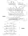
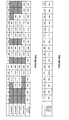
- FIG. 1 Representations of the fixed and flexible grid approaches are depicted in the example graphs shown in Figure 1 , in which graphs (a), (c) and (d) depict examples of fixed grid implementations, while (b) and (e) illustrates the flexgrid approach.
- Graph (a) illustrates the strict guard bands partitioning adjoining optical channels in a fixed grid implementation, and demands or wavelengths at a particular bit rate.
- Graph (b) shows how the channels for the demand can be grouped into a single "superchannel" which can be transported as one entity in a flexgrid system.
- graph (c) five demands (of varying bit rates and distances) and their spectrum needs are shown on a fixed grid, assuming quaternary phase shift keying (QPSK) modulation.
- QPSK quaternary phase shift keying
- Graph (d) depicts the same service demands of graph (c), with adaptive modulation optimized for the required bit rate and reach.
- Arbitrary-size spectrum slot allocation is shown in the flexgrid implementation of graph (e) which has the same demands as graphs (c) and (d).
- the spectrum savings that may be achieved using a flexgrid approach may be seen by a comparison between the fixed grid scheme shown in (d) and an identical scenario when used under the flexgrid scheme shown in (e).
- moving away from the use of fixed-position guard bands defining channel widths in the fixed grid approach can achieve efficiencies by spacing channels contiguously or at least closer to each other, across the spectrum. This can result in the freeing up of spectrum resource for other demands.
- the flexgrid scheme allows greater flexibility and choice in allocating spectrum.
- a drawback suffered particularly by flexgrid systems is that the optical spectrum can become "fragmented", consisting of non-contiguous used spectrum sections in a manner akin to a computer hard disk including fragmented disk blocks. This is because when a signal or demand reaches its destination node, the optical connection terminates and the wavelength or channel "vacates" the spectrum slot.
- One way of preventing spectrum fragmentation is to find a new resource request having an identical or near-identical slot width, to occupy that slot just at the point when the slot becomes available. The chances of such coincidences occurring are, however, not high, and as may be expected, such vacated slots are likely to remain wholly or partly unfilled.
- graph (e) of Figure 1 depicts an optimal situation in a flexgrid environment, in which the demands essentially occupy contiguous positions in the spectrum.
- fragments of unused "stranded" spectrum fragments can be represented as gaps between neighbouring used slots, as shown in e.g. Figure 3 (discussed below). It can be expected that failure to address this problem may eventually result in significant inefficiencies in the use of the precious spectrum resource, possibly resulting in the need to build expensive new links to cope with traffic levels.
- a routing and wavelength assignment method for use in an optical fibre system comprising
- Routing and Wavelength Assignment RWA
- RSA Routing and Spectrum Assignment
- apparatus such as a processor for use in an optical fibre system configured to perform one or more of the functions of:
- Figure 1 illustrates the differences in the fixed grid and flexgrid paradigms, and a comparison of graphs (d) (depicting fixed grid spectrum use) and graph (e) (flexgrid) highlights the spectrum savings that can be achieved using flexgrid.
- the following describes how a usable entropy metric can be calculated for any system with suitable characteristics.
- a worked example is also discussed in connection with Figures 3 to 5 , to demonstrate an application of an entropy metric in the specific context of fragmentable optical spectrum resources.
- the fragmentation entropy metric or measure obtained using the method described herein takes into account distinguishable minimum-entropy states and degrees of freedom in multi-granular/wavelength link traffic demands.
- the method takes from the Shannon theory of information, and is based on the Boltzmann approach of countable and distinguishable states. The result is monotonic and scale-less, and discriminates varying spectrum topological complexity for efficient resource management.
- a system can exist in N different "states" (as will be described in more detail below), wherein the probability of existing in the i th state is p i .
- the first (top-most) and last (bottom-most) spectra depict respectively the least and the most fragmented versions of the resource (in which empty boxes depict unfilled slots and black boxes depicted filled slots).
- the first-order requirement is that the resource be as unfragmented as possible.
- management of a. complex topology comprising a puzzle of interstitially-inserted resources (such as the lbst-depicted spectrum in Figure 2 ) is more problematic than in a less fragmented system.
- resource fragmentation is created when e.g. a demand or requirement previously in use is removed from the system, which is likely to worsen over time if left unchecked, particular in flexgrid implementations.
- An appropriate tool will be required to assess the relative topological complexity and/or fragmentation of the resource utilisation from time to time or on an ongoing basis.
- Maintenance in the form of e.g. spectrum re-ordering and re-allocation (akin to a "defragmentation" of a computer hard disk) will have to carried out to ensure efficient use of the available spectrum resource. This is potentially costly and disruptive as operations have to be temporarily halted while the spectrum defragmentation takes place. Having an entropic measure or metric will allow the network owner or operator to take informed decisions about when and how to undergo such maintenance, or test and diagnosis.
- a start point is the fill-factor f , which has a value lying between 0 and 1.
- the fill-factor f indicates the fraction of the optical spectrum being consumed by the total number of data channels present.
- the fragmentation entropy of this unfragmented spectral case is referred to as H min , since it represents the lower bound of the system fragmentation entropy for any given fill-factor f .
- a fragmented spectrum on the other hand, comprises separated chunks of used or unused optical resource each of which represents different states or blocks of the system.
- the states or blocks of the system are defined by considering the optical spectrum to be represented by a set of N different number of blocks of spectral resource.
- Each state or block consists of either a single wavelength or data channel, or a contiguous set of multiple data channels but each of the same kind and spectral width, e.g. all 10G, 40G, or 100G, etc.
- N 11 states or blocks, in which state 1 comprises one 10G channel, while state 5 comprises two 40G channels.
- a block of resource can therefore also represent either a single or a contiguous set of unused optical spectrum quanta (see states 2 and 4 respectively, in Figure 3 ); in which case the single (or repeated) channel is of unit spectral width q .
- each block represents a maximally unfragmented (minimum entropy, MinEnt, or minimum topological complexity) sub-domain of the overall optical spectrum. This is because the position occupied by any one of the channels within a particular block is irrelevant to the entropy measure of the block, so that the entropy of the block itself can be thought of as a constant. Accordingly, swapping or shuffling channels within a block offers no advantage or difference in terms of optimal exploitation of the overall spectral resource.
- the total (i.e. filled + unfilled) spectrum resource within an optical fibre is assumed to be Pq , i.e. there are a total of P spectral quanta of total resource.
- each individual data channel (10G, 40G, 100G, etc.) as well as each unfilled quantum q , to represent a single "degree of freedom" (DoF) of the system, which is independent of the actual spectral width that each DoF represents.
- DoF can be of varying spectral width, in the same way as a block or state.
- a state or block can comprise more than one channel or unused section(s) of spectrum, so referring again to Figure 3 , there are 2 DoFs in each of e.g., states 4 and 5.
- Characterising the data channels in DoF terms allows for appropriate account to be taken of the differing spectral widths of channels (and unused or free spectrum) especially in a flexgrid implementation. As would be expected, each DoF of the optical spectrum affects the overall entropy behaviour of the optical spectrum.
- This formula provides a highly versatile and usable measure of resource fragmentation entropy and topological complexity, which gives system or network owners or operators information allowing for e.g. defragmentation or other maintenance activity to be carried out on the system.
- the metric can be used to make routing and wavelength assignment decisions, as will be discussed below. The metric can be obtained on the unused section of the spectrum, the used section, or both.
- the spectrum of an optical fibre is deemed to be completely unfragmented (i.e. with minimum topological complexity) where the spectrum is completely unfilled, or else completely filled to capacity with exactly the same sized channels (e.g. all 10G signals).
- the spectrum is completely full (e.g. with only 10G channels)
- the entropy-based fragmentation entropy metric can have an absolute minimum value of zero.
- an entropy metric can be calculated by considering the optical spectrum in terms of a number of slots representing the individual flexgrid quanta. These can then be grouped into N contiguous blocks consisting of either used (coming from any number of individual signals) or unused spectrum.
- the Shannon entropy metric H Frag of a spectrum can then be calculated using the formula (2) noted above. Large values of H Frag indicate higher levels of fragmentation.
- the entropy levels of the spectrum resources shown in Figure 2 have been calculated using this approach.
- the first (top-most) example shows a completely unused spectrum which has a H Frag value of zero; as expected, a completely filled spectrum would also have a fragmentation metric of zero.
- the remaining examples show that for the same amount of free spectrum (represented by an equal number of filled and unfilled slots), the value of H Frag varies (and increases monotonically) depending on the amount of fragmentation, which reaches a maximum in the last example comprising alternating filled and unfilled slots.
- One advantage of this approach is that longer contiguous blocks of used or unused spectrum, which are more useful for accommodating future demands, tend to result in lower overall fragmentation entropy levels,
- Figure 3 depicts an example of an optical spectrum partly filled with data channels of differing bandwidths.
- the y-axis depicts channel power, while the x-axis is a representation of the spectrum resource.
- N 11 available blocks (i.e. representing 11 states) for this particular spectrum configuration.
- block or state 1 comprises a 10G data channel
- block 2 is "unused" (U) spectrum
- block 3 comprises a 100G data channel
- block 4 comprises 2 unused quanta of spectrum, and so on.
- the resource is fragmented in that it comprises used sections as well as unfilled sections.
- Each channel (U (or q ), 10G, 40G or 100G, etc.) is considered to be a single DoF and can be a state in itself (e.g.
- Figure 4 depicts the optical frequency spectral distribution of the example shown in Figure 3 in terms of its state-space distribution.
- Each state 1 to 11 is again depicted along the x-axis.
- the channels within the states are represented in terms of its DoFs, so for example there is in state 2, 1 DoF (out of a total of 14 DoFs), while in state 4 there are 2 DoFs (out of a total of 14 DoFs).
- each bar in each state graphically represents the number of DoFs in each state (so the bar in state 4 is twice the height of that in state 2), which is numerically confirmed by the figures appearing above each bar (1/14 and 2/14 respectively in states 2 and 4).
- the view of the spectrum resource from the optical frequency view of Figure 3 to the state-space view in Figure 4 it is irrelevant whether the channels are arranged from left to right, or vice-versa.
- the 10G channels for example, while they previously occupied states 1, 6, 8 and 11 (in Figure 3 ), they now are arranged contiguously to form a single block in state 2.
- the fragmentation metric is monotonic makes it useful when considering the relative topological complexity of a fragmented spectrum.
- a monotonic metric offers a measure of the degree of fragmentation and topological complexity of a particular spectrum configuration. So for example, even for the case of Figure 3 and Figure 5(a) where the fill-factor (i.e. spectrum capacity utilisation) is the same for both cases, the lower fragmentation metric for Figure 5(a) confirms what we can visually ascertain as its lower fragmentation, and its relatively more simple topological-complexity.
- the used spectrum channels of Figure 5(a) were actually all identical, e.g. only 10G channels, (i.e.
- the above approach to derive the entropy metric is essentially scale-less (due to its logarithmic nature) and therefore can be applied in sub-networks, national, and pan-national networks in a naturally additive fashion. Usefully, additionally because of its monotonic behaviour, it enables measurements of the fine differences between the performances of different defragmentation and RSA algorithms, and achieve optimum network resource exploitation. Furthermore, a link RSA having both local and global properties (e.g. modifying the spectral allocations of a local link will have global implications across the network), the entropic approach to measuring the state of disorder of links in a photonic network is analogous to measuring the entropy of a gas of particles, where each particle exhibits both local and global properties (i.e.
- a particle has a statistical distribution of short-range to long-range interactions/collisions with the other particles in the gas.
- the entropy metrics derived from the Shannon-based approach described in the previous section can be applied to routing issues in at least two ways.
- the first method is based on a "link-based” minimised entropy measure (MinEnt) where the spectrum of each link along a particular path is considered in isolation.
- MinEnt minimised entropy measure
- the second way it can be applied is a "path-based” MinEnt where the spectrum profiles along all the links in the path are combined together to form a single end-to-end profile.
- RWA Routing and Wavelength Assignment
- RSA Routing and Spectrum Assignment
- NMS network management systems
- Embodiments and implementations of the invention seek to include entropy measures into routing and spectrum assignment decisions to find a routing and spectrum assignment that minimises entropy. This is achieved by use of an algorithm which assigns routes and spectrum by allotting the smallest slot which can accommodate the particular demand, in order to keep larger (contiguous) blocks of spectrum free, and/or for larger demands that need it. In this way, demands of narrower spectral width are not assigned to a large slot where a narrower but suitable slot is available, thus reducing the creation of unused sections next to the newly-occupied slot and allowing for a higher number of demands of various sizes to be supported by making better use of the spectrum.
- the entropy measure routine could be based on the approach described above using a version of e.g. formula (2) described above to obtain the H Frag value.
- the entropy value is calculated only for the unused spectral components of a given optical spectrum by finding each block of unused spectrum and calculating the following: number_of_unused_slots / total_slots_across_spectrum * LN number_of_unused_slots / total_slots_across_spectrum where LN is the natural logarithm, and the "total_slots" is equal to the total number of spectrum slots (unused and used) across the whole spectrum band.
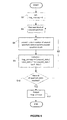
- the flow chart of Figure 6 depicts the steps involved in calculating the entropy measure of a given spectrum resource, in which the process begins, by setting the entropy value ("frag_entropy") to zero (step S2).
- a block of unused spectrum is found (step S4) and the number of unused slots ("unused_slots") discovered up to that point is recorded (step S6).
- the fragmentation entropy level for the unused spectrum block under consideration is calculated using the above formula (step S8).
- step S10 If there are still unused blocks to be processed (step S10), the steps are iterated until all the blocks in the spectrum have been processed, at which point the entropy metric is obtained (step S12) by adding together all the entropy level values of each unused spectrum block to get an overall calculation of the unused-spectrum fragmentation entropy.
- the obtained entropy measure sits at the heart of the routing process described in the flow chart set out in Figures 7(a) and 7(b) .
- the approach involves the finding of a route though the optical network which has the lowest unused-spectrum fragmentation entropy, which is achieved by replacing the conventional lowest-cost path algorithm with a fragmentation entropy metric obtained by the exemplary method shown in Figure 6 .
- This requires the used spectrum state of each branch of the network to be stored and the spectrum of each additional hop under consideration needs to be added to these states.
- the fragmentation entropy of the spectrum is calculated using the formula given above.
- discovery of the path with the lowest unused-spectrum fragmentation entropy path allows the network owner or operator to select a spectrum allocation which reduces the level of end-to-end fragmentation entropy along the chosen path, or else causes the fragmentation entropy to increase by the smallest amount.
- the spectrum required for the transceiver is placed in every position along the entire spectrum. If for a given position the spectrum is currently unused, then the fragmentation entropy is calculated as set out in the flow chart of Figure 6 .
- the lowest unused-spectrum fragmentation entropy state is stored. Once identified, the routing and spectrum assignment is output to the NMS to be configured on the network nodes.
- the two steps (of identifying and applying the entropy metric) can be more tightly coupled to form a single step, which might require additional computational time and resources.
- routing traffic in this manner would realise a network having an overall lower entropy measure, which will allow for bigger sections to remain available allowing for accommodation of future demands.
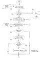
- step S22 information about the topology and state of the network is used to find a number n of paths between source A and destination B (step S22) using conventional methods e.g. based on Dijkstra's algorithm.
- step S24 no path is found
- step S26 the process is blocked
- step S28 the used spectrum profile of that path determined
- step S30 the profile of the transceiver device (which is carrying the traffic between source and destination) is applied to the path spectrum profile (step S30) at a first location along the spectrum profile.
- step S32 which includes the routine set out in Figure 6
- the fragmentation entropy of the newly-identified path is calculated (step S34).
- a comparison is then made of the entropy levels of the latest-discovered path with any previously-discovered paths based on the spectrum configuration that would result from using the latest-discovered path (step S36), and the spectrum allocation in question is stored (step S38).
- the transceiver profile is now along by one slot to allow further placements along the spectrum to be checked (step S41).
- step S40 When the spectrum has been fully searched (step S40) and the lowest entropy allocation for this spectrum has been found for this new demand along the current considered path (step S42), a comparison with previously-discovered paths is made to determine if the latest-discovered path has the lowest entropy rating (step S44). If it does, the path and spectrum allocation is stored (step S46). The steps to find the path with the lowest entropy value are iterated until all n paths initially identified in step S22 have been checked (steps S48 and S49). If no spectrum and path combination to the destination node B has been identified, the process is blocked (step S52) and terminates. Otherwise, the path and spectrum allocation generating the least entropy in the spectrum resource is selected. (steps S50 and S54), which seeks to guard against "waste" of the spectrum, e.g. avoid placing new demands within a large unused slot when narrower but suitable slots are also available.
- the spectrum of each link or hop (i.e. between nodes) along a particular path is considered separately from each of the spectrums of the other links along the path.
- the spectrum profile of each link is searched to find starting locations with enough free spectrum slots to support the transceiver's spectral width.
- the change in the entropy levels of a spectrum in which the new signal is placed is calculated. All other slots or positions which have insufficient spectral capacity, are ascribed an infinite delta (or change in entropy). This is repeated for the remaining links in the path and the sum of entropy deltas taken. The frequency slot with the lowest sum of entropy deltas is then selected.
- Figure 8(a) depicts a path comprising 4 links (S1 to S4) with 16 frequency slots ( f1 to f16 ) along the spectra of each link.
- the empty boxes depict unfilled slots and black boxes depicted filled slots, so it can be seen that all the spectra are fragmented to varying degrees.
- End-to-end paths for single-slot demands are available through all 4 links in slots f5 , f6 , f8 , f9 , f11 , f12 and f13.
- a new demand requiring 2 slots needs to be placed on the path, for which there is end-to-end path availability in slots f5 , f8 , f11 and f12.
- the values in the boxes show the entropy change or delta ( ⁇ Hfrag) if the new demand is placed starting at that location. These are obtained using the entropy calculation method described above for each link. Referring to link S1 as an example, slot f4 has an available slot next to it (slot f5 ) and so can accommodate a 2-slot demand. If it takes on the demand, the entropy delta value is -0.141. Slot f5 has identical characteristics, and so will also have an entropy delta value of -0.141 if it takes on the demand.
- the second way entropy measures can be applied in routing decisions is based on a path-based MinEnt value, where the spectrum profiles along all the links in the path are combined together to form a single end-to-end profile which is then searched to find the spectrum allocation that produces the smallest entropy delta.
- Figures 9 and 10 provide a view of network performance against increasing demand levels over time, and illustrate the different results using the three RSA schemes.
- the curves shown in Figure 9 show how the overall unused-spectrum network fragmentation entropy (the sum of the unused-spectrum fragmentation entropies across all network links) evolves as demands are added, in which the average network entropy on the y-axis is plotted against the level of demand on the x-axis.
- Figure 10 shows how the overall network utilisation (the amount of used spectrum across all links) evolves, and plots the average network fill factor (i.e capacity used, on the y-axis) against demand (on the x-axis).
- the projections based on the three RSA scheme are depicted for comparative purposes: the link-based MinEnt data is depicted by line (a), the path-based MinEnt data by line (b), and the classical shortest-path routing with first-fit spectrum assignment is indicated by line (c).
- Figure 10 shows that network utilisation of link-based MinEnt schemes initially follows the classical result closely, indicating that similar length routes are being selected by both schemes.
- line (a) of the link-based MinEnt spectrum allocation approach gradually diverges from the result of the classical approach, indicating that demands can be allocated even as the classical routing and allocation approach starts to slow down on that front.
- curve (b) shows that its use results in greater overall levels of entropy, but of greater critical importance, results in faster consumption of overall network resource.
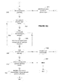
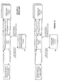
- FIG 11 is a schematic view of the process flows between the network components used in routing and allocation management in a conventional set up.
- the main functional block is the NMS (100) which sends and receives instructions.
- the process typically commences with a requestor a connection to be made between source node A and destination node B .
- This request is sent to the NMS (step S61), which seeks and obtains data about the network state (steps S62 and S63).
- This information is then used to discover a suitable path based on the network state (step S64), which according to standard RSA methods (86) would include shortest-path calculations.
- the identified path is then returned (step S65) to the NMS.
- the WDM transceivers (102) are then configured (steps S66 and S67) to place the signal along the path identified for that purpose.
- Figure 12 illustrates the relative ease with which an entropy-based metric can be deployed within the routing system by replacement of the conventional RSA method with a process or routine for calculating the entropy metric of the path or the link as the case may be.
- the system may include entropy calculations in addition to standard routing decisions, and that both the link- and path-based methods could in suitable cases allow for deeper analyses of the network and identified routes to be carried out before a decision is taken.
- entropy based fragmentation RSA techniques can also be applied in fixed grid scenarios to select a path and wavelength channel which reuses released channels in the network more optimally than starting to make use of a new wavelength that is currently unused in the network. It would also be appreciated that such entropy measures can be advantageously applied in a variety of situations, not being restricted to use only in respect of identifying network routes.
Landscapes
- Engineering & Computer Science (AREA)
- Computer Networks & Wireless Communication (AREA)
- Signal Processing (AREA)
- Data Exchanges In Wide-Area Networks (AREA)
- Optical Communication System (AREA)
Priority Applications (5)
| Application Number | Priority Date | Filing Date | Title |
|---|---|---|---|
| EP13250053.9A EP2797247A1 (fr) | 2013-04-24 | 2013-04-24 | Transmission de données optiques |
| EP14720199.0A EP2989735B1 (fr) | 2013-04-24 | 2014-04-24 | Transmission de données optiques |
| CN201480036141.7A CN105359442B (zh) | 2013-04-24 | 2014-04-24 | 网络管理系统、处理器及路由和波长分配方法 |
| PCT/GB2014/000155 WO2014174234A1 (fr) | 2013-04-24 | 2014-04-24 | Transmission optique de données |
| US14/786,399 US9860012B2 (en) | 2013-04-24 | 2014-04-24 | Optical data transmission |
Applications Claiming Priority (1)
| Application Number | Priority Date | Filing Date | Title |
|---|---|---|---|
| EP13250053.9A EP2797247A1 (fr) | 2013-04-24 | 2013-04-24 | Transmission de données optiques |
Publications (1)
| Publication Number | Publication Date |
|---|---|
| EP2797247A1 true EP2797247A1 (fr) | 2014-10-29 |
Family
ID=48520851
Family Applications (2)
| Application Number | Title | Priority Date | Filing Date |
|---|---|---|---|
| EP13250053.9A Ceased EP2797247A1 (fr) | 2013-04-24 | 2013-04-24 | Transmission de données optiques |
| EP14720199.0A Active EP2989735B1 (fr) | 2013-04-24 | 2014-04-24 | Transmission de données optiques |
Family Applications After (1)
| Application Number | Title | Priority Date | Filing Date |
|---|---|---|---|
| EP14720199.0A Active EP2989735B1 (fr) | 2013-04-24 | 2014-04-24 | Transmission de données optiques |
Country Status (4)
| Country | Link |
|---|---|
| US (1) | US9860012B2 (fr) |
| EP (2) | EP2797247A1 (fr) |
| CN (1) | CN105359442B (fr) |
| WO (1) | WO2014174234A1 (fr) |
Cited By (3)
| Publication number | Priority date | Publication date | Assignee | Title |
|---|---|---|---|---|
| WO2016156300A1 (fr) * | 2015-03-30 | 2016-10-06 | British Telecommunications Public Limited Company | Conception de réseau optique et routage |
| US9654248B2 (en) | 2013-10-11 | 2017-05-16 | British Telecommunications Public Limited Company | Optical data transmission method and apparatus |
| US9860012B2 (en) | 2013-04-24 | 2018-01-02 | British Telecommunications Public Limited Company | Optical data transmission |
Families Citing this family (16)
| Publication number | Priority date | Publication date | Assignee | Title |
|---|---|---|---|---|
| GB201305801D0 (en) | 2013-03-28 | 2013-05-15 | British Telecomm | Optical switch |
| GB201305985D0 (en) | 2013-04-03 | 2013-05-15 | British Telecomm | Optical switch |
| US9602427B2 (en) * | 2014-02-06 | 2017-03-21 | Nec Corporation | Cloud service embedding with shared protection in software-defined flexible-grid optical transport networks |
| CN105472484B (zh) * | 2015-11-11 | 2018-11-27 | 国家电网公司 | 一种电力骨干光传输网波道均衡路由波长分配方法 |
| US9686599B2 (en) * | 2015-11-18 | 2017-06-20 | Ciena Corporation | Minimal spectrum occupancy systems and methods for routing and wavelength or spectrum assignment in optical networks |
| US9941992B2 (en) * | 2016-09-14 | 2018-04-10 | Futurewei Technologies, Inc. | Method and apparatus for efficient network utilization using superchannels |
| US10892822B2 (en) | 2017-02-01 | 2021-01-12 | British Telecommunications Public Limited Company | Optical fiber event location |
| WO2018166920A1 (fr) | 2017-03-16 | 2018-09-20 | British Telecommunications Public Limited Company | Distribution de clé quantique dans un réseau de communication optique |
| WO2019016263A1 (fr) | 2017-07-20 | 2019-01-24 | British Telecommunications Public Limited Company | Fibre optique |
| EP3471299A1 (fr) | 2017-10-11 | 2019-04-17 | Xieon Networks S.à r.l. | Procédé et système de gestion d'ensemble de format de canal multimédia dans des réseaux de transport optique |
| WO2019137734A1 (fr) | 2018-01-09 | 2019-07-18 | British Telecommunications Public Limited Company | Système de transmission optique de données |
| EP3644532A1 (fr) * | 2018-10-23 | 2020-04-29 | Xieon Networks S.à r.l. | Procédé et système pour attribuer des ressources spectrales |
| EP3771153B1 (fr) * | 2018-12-17 | 2023-06-07 | ECI Telecom Ltd. | Services de migration dans des réseaux de communication de données |
| US10873411B1 (en) * | 2019-10-23 | 2020-12-22 | Cisco Technology, Inc. | Optimizing spectral efficiency for a configuration of an optical network |
| CN110996196B (zh) * | 2019-12-18 | 2022-04-12 | 中邮科通信技术股份有限公司 | 一种光传输网光路纤芯利用的最优路由寻优方法 |
| US11611405B2 (en) * | 2020-08-11 | 2023-03-21 | Microsoft Technology Licensing, Llc | Efficient spectrum allocation in a multi-node optical network |
Citations (3)
| Publication number | Priority date | Publication date | Assignee | Title |
|---|---|---|---|---|
| US20030072052A1 (en) * | 2001-10-10 | 2003-04-17 | Graves Alan F. | Optical wavelength plan for metropolitan photonic network |
| EP2403169A1 (fr) * | 2010-06-29 | 2012-01-04 | Alcatel Lucent | Procédé dans un réseau optique pour l'affectation de la totalité de la largeur de bande optique |
| US20120251117A1 (en) * | 2011-03-30 | 2012-10-04 | Nec Laboratories America, Inc. | Method for Traffic Grooming, Wavelength Assignment and Spectrum Allocation |
Family Cites Families (69)
| Publication number | Priority date | Publication date | Assignee | Title |
|---|---|---|---|---|
| US3259693A (en) | 1960-09-28 | 1966-07-05 | Nippon Electric Co | Frequency division multiplex communication system |
| US4731878A (en) | 1985-11-29 | 1988-03-15 | American Telephone And Telegraph Company, At&T Bell Laboratories | Self-routing switch node combining electronic and photonic switching |
| US5586128A (en) | 1994-11-17 | 1996-12-17 | Ericsson Ge Mobile Communications Inc. | System for decoding digital data using a variable decision depth |
| US6476945B1 (en) | 1999-06-01 | 2002-11-05 | Nortel Networks Limited | Wavelength allocation in a ring |
| US6275470B1 (en) | 1999-06-18 | 2001-08-14 | Digital Island, Inc. | On-demand overlay routing for computer-based communication networks |
| US6529301B1 (en) | 1999-07-29 | 2003-03-04 | Nortel Networks Limited | Optical switch and protocols for use therewith |
| JP2002064259A (ja) | 2000-08-18 | 2002-02-28 | Kanegafuchi Chem Ind Co Ltd | 耐熱性フレキシブル基板の製造方法 |
| US6738354B1 (en) | 2000-02-18 | 2004-05-18 | Nortel Networks Limited | Label selection for end-to-end label-switched traffic through a communications network |
| US6519062B1 (en) | 2000-02-29 | 2003-02-11 | The Regents Of The University Of California | Ultra-low latency multi-protocol optical routers for the next generation internet |
| US6763190B2 (en) | 2000-03-03 | 2004-07-13 | Lucent Technologies Inc. | Network auto-provisioning and distributed restoration |
| EP1162855B1 (fr) | 2000-06-05 | 2005-12-07 | PIRELLI CAVI E SISTEMI S.p.A. | Réseau optique à multiplexage en longueur d'onde avec une combinaison de routage par longeurs d'onde et de routage de fibres optiques |
| US6775230B1 (en) | 2000-07-18 | 2004-08-10 | Hitachi, Ltd. | Apparatus and method for transmitting frames via a switch in a storage area network |
| JP4378882B2 (ja) | 2001-01-17 | 2009-12-09 | 日本電気株式会社 | 光通信ネットワーク、中継増幅装置及びそれらに用いる通信制御方法 |
| US6757495B2 (en) | 2001-01-30 | 2004-06-29 | The Regents Of The University Of California | Optical layer multicasting using a multiple sub-carrier header and a multicast switch with active header insertion via single sideband optical processing |
| US6850705B2 (en) | 2001-03-17 | 2005-02-01 | Fujitsu Limited | Online distributed path routing method and system |
| US20020191247A1 (en) | 2001-04-30 | 2002-12-19 | Xiang Lu | Fast restoration in optical mesh network |
| US20030016410A1 (en) | 2001-07-18 | 2003-01-23 | Innovance Networks | Method for engineering connections in a dynamically reconfigurable photonic switched network |
| US20030007724A1 (en) | 2001-07-05 | 2003-01-09 | Broadcom Corporation | System, method, and computer program product for optimizing video service in ethernet-based fiber optic TDMA networks |
| US7599621B2 (en) | 2001-07-19 | 2009-10-06 | Alcatel-Lucent Usa Inc. | Trail engineering in agile photonic networks |
| US7171124B2 (en) | 2001-07-19 | 2007-01-30 | Lucent Technologies Inc. | Wavelength routing and switching mechanism for a photonic transport network |
| US20030043427A1 (en) | 2001-08-30 | 2003-03-06 | Marc Robidas | Method of fast circuit recovery using local restoration |
| US7113481B2 (en) | 2001-10-10 | 2006-09-26 | Alcatel | Informed dynamic path protection for optical networks |
| US7362974B2 (en) | 2001-11-30 | 2008-04-22 | Pirelli & C. S.P.A. | Method for planning or provisioning data transport networks |
| US7190902B2 (en) | 2001-12-12 | 2007-03-13 | Lucent Technologies Inc. | Wavelength exerciser |
| US7249169B2 (en) | 2001-12-28 | 2007-07-24 | Nortel Networks Limited | System and method for network control and provisioning |
| US7664029B2 (en) | 2002-02-21 | 2010-02-16 | Alcatel | Method of determining a spectral route for a given connection in an optical telecommunications network |
| CA2425721C (fr) | 2002-04-19 | 2009-03-10 | Nippon Telegraph And Telephone Corporation | Reseau de communication a trajet optique, noeud et methode d'etablissement de trajet optique |
| DE60220549T2 (de) | 2002-05-17 | 2008-02-07 | Telefonaktiebolaget Lm Ericsson (Publ) | Dynamische Wegeleitung in einem paketvermittelden mehrschichtigen Kommunikationsnetzwerk |
| US20040120705A1 (en) | 2002-12-18 | 2004-06-24 | Robert Friskney | Differentiated resilience in optical networks |
| US7403713B2 (en) | 2003-03-05 | 2008-07-22 | University Of Hertfordshire | Quantum source coding apparatus and quantum information communication system |
| US7224897B1 (en) | 2003-04-28 | 2007-05-29 | Lucent Technologies Inc. | Method of preconfiguring optical protection trails in a mesh-connected agile photonic network |
| US20040220886A1 (en) | 2003-04-30 | 2004-11-04 | Lucent Technologies, Inc. | Communication signal resource chain assignment for optical networks subject to reach constraints |
| US7283741B2 (en) | 2003-06-06 | 2007-10-16 | Intellambda Systems, Inc. | Optical reroutable redundancy scheme |
| US7860392B2 (en) | 2003-06-06 | 2010-12-28 | Dynamic Method Enterprises Limited | Optical network topology databases based on a set of connectivity constraints |
| US20040252996A1 (en) | 2003-06-10 | 2004-12-16 | Nortel Networks Limited | Flexible banded MUX/DEMUX architecture for WDM systems |
| FR2857531B1 (fr) | 2003-07-11 | 2005-12-02 | Cit Alcatel | Procede pour determiner une route spectrale dans un reseau de telecommunication optique |
| DE10333805B4 (de) | 2003-07-24 | 2016-04-07 | Xieon Networks S.À.R.L. | Verfahren zur Ermittlung eines Verbindungspfades und eines zugehörigen unbelegten Wellenlängenkanals |
| US7725035B2 (en) | 2004-04-20 | 2010-05-25 | Fujitsu Limited | Method and system for managing network traffic |
| GB0416110D0 (en) | 2004-07-19 | 2004-08-18 | British Telecomm | Path establishment |
| GB0416107D0 (en) | 2004-07-19 | 2004-08-18 | British Telecomm | Wavelength selection |
| JP4606333B2 (ja) | 2005-09-20 | 2011-01-05 | 富士通株式会社 | ルーティング制御方法 |
| JP4899643B2 (ja) | 2006-05-31 | 2012-03-21 | 富士通株式会社 | ネットワーク構成装置 |
| US7843823B2 (en) | 2006-07-28 | 2010-11-30 | Cisco Technology, Inc. | Techniques for balancing throughput and compression in a network communication system |
| US8238749B2 (en) | 2007-08-27 | 2012-08-07 | Futurewei Technologies, Inc. | Distributing wavelength compatible with signaling protocols |
| US8954562B2 (en) | 2007-09-28 | 2015-02-10 | Intel Corporation | Entropy-based (self-organizing) stability management |
| EP2209325A1 (fr) | 2009-01-15 | 2010-07-21 | BRITISH TELECOMMUNICATIONS public limited company | Gestion de connexions de télécommunications |
| US8457001B2 (en) | 2010-04-23 | 2013-06-04 | Ciena Corporation | Mesh restoration in optical transport networks |
| US8666247B2 (en) | 2010-08-25 | 2014-03-04 | Ciena Corporation | Bandwidth defragmentation systems and methods in optical networks |
| US8705963B2 (en) * | 2010-09-17 | 2014-04-22 | Nec Laboratories America, Inc. | K-alternate channel selection for the routing, wavelength assignment and spectrum allocation in flexible optical WDM networks |
| US8948048B2 (en) | 2010-12-15 | 2015-02-03 | At&T Intellectual Property I, L.P. | Method and apparatus for characterizing infrastructure of a cellular network |
| US8909043B2 (en) * | 2011-02-04 | 2014-12-09 | Nec Laboratories America, Inc. | Routing, wavelength assignment, and spectrum allocation in wavelength convertible flexible optical wavelength-division multiplexing networks |
| US8553702B2 (en) | 2011-05-18 | 2013-10-08 | Ciena Corporation | Methods and systems for automatic carving and policy enforcement for optical transport network hierarchy |
| US8553551B2 (en) | 2011-06-12 | 2013-10-08 | Oliver Solutions Ltd. | Dynamic bandwidth allocation for upstream transmission in passive optical networks |
| US9496886B2 (en) | 2011-06-16 | 2016-11-15 | Spatial Digital Systems, Inc. | System for processing data streams |
| US8942114B2 (en) | 2011-06-21 | 2015-01-27 | Fujitsu Limited | System and method for calculating utilization entropy |
| US9020350B2 (en) | 2011-06-24 | 2015-04-28 | Techsys Insights | Optical spectrum recovery |
| US8902920B2 (en) * | 2011-06-27 | 2014-12-02 | University Of Massachusetts | Dynamic advance reservation with delayed allocation |
| US8681649B2 (en) | 2011-08-01 | 2014-03-25 | Cisco Technology, Inc. | System and method for adaptive optimization of resource utilization for redundancy elimination |
| US9252912B2 (en) | 2012-04-09 | 2016-02-02 | Telefonaktiebolaget L M Ericsson (Publ) | Method for routing and spectrum assignment |
| US9083485B2 (en) | 2012-04-12 | 2015-07-14 | Fujitsu Limited | Defragmentation of optical networks |
| US20130272711A1 (en) | 2012-04-13 | 2013-10-17 | Nec Laboratories America, Inc. | Light-Tree Provisioning for Multicast Traffic in Flexible Optical WDM Networks |
| US9054829B2 (en) | 2012-07-11 | 2015-06-09 | Nec Laboratories America, Inc. | Spectrum aware rate selection procedure for optical channels in flexible WDM networks |
| US20140029939A1 (en) | 2012-07-26 | 2014-01-30 | Nec Laboratories America, Inc. | Blocking Estimation To Evaluate Connection Blocking In Flexible Optical WDM Networks |
| US9160477B2 (en) | 2013-02-14 | 2015-10-13 | Nec Laboratories America, Inc. | Virtual networking embedding procedure in an optical wavelength division multiplexing (WDM) network |
| EP2797247A1 (fr) | 2013-04-24 | 2014-10-29 | British Telecommunications Public Limited Company | Transmission de données optiques |
| US9060215B2 (en) | 2013-05-10 | 2015-06-16 | Ciena Corporation | Network specific routing and wavelength assignment for optical communications networks |
| US9247327B2 (en) | 2013-10-10 | 2016-01-26 | Nec Laboratories America, Inc. | Suurballe-based cloud service embedding procedure in software-defined flexible-grid optical transport networks |
| WO2015052468A1 (fr) | 2013-10-11 | 2015-04-16 | British Telecommunications Public Limited Company | Procédé et appareil d'émission de données optiques |
| CN104467969B (zh) | 2014-12-10 | 2017-03-22 | 北京理工大学 | 分数阶傅里叶变换测量光纤链路色散的方法 |
-
2013
- 2013-04-24 EP EP13250053.9A patent/EP2797247A1/fr not_active Ceased
-
2014
- 2014-04-24 WO PCT/GB2014/000155 patent/WO2014174234A1/fr active Application Filing
- 2014-04-24 EP EP14720199.0A patent/EP2989735B1/fr active Active
- 2014-04-24 CN CN201480036141.7A patent/CN105359442B/zh active Active
- 2014-04-24 US US14/786,399 patent/US9860012B2/en active Active
Patent Citations (3)
| Publication number | Priority date | Publication date | Assignee | Title |
|---|---|---|---|---|
| US20030072052A1 (en) * | 2001-10-10 | 2003-04-17 | Graves Alan F. | Optical wavelength plan for metropolitan photonic network |
| EP2403169A1 (fr) * | 2010-06-29 | 2012-01-04 | Alcatel Lucent | Procédé dans un réseau optique pour l'affectation de la totalité de la largeur de bande optique |
| US20120251117A1 (en) * | 2011-03-30 | 2012-10-04 | Nec Laboratories America, Inc. | Method for Traffic Grooming, Wavelength Assignment and Spectrum Allocation |
Non-Patent Citations (2)
Cited By (6)
| Publication number | Priority date | Publication date | Assignee | Title |
|---|---|---|---|---|
| US9860012B2 (en) | 2013-04-24 | 2018-01-02 | British Telecommunications Public Limited Company | Optical data transmission |
| US9654248B2 (en) | 2013-10-11 | 2017-05-16 | British Telecommunications Public Limited Company | Optical data transmission method and apparatus |
| WO2016156300A1 (fr) * | 2015-03-30 | 2016-10-06 | British Telecommunications Public Limited Company | Conception de réseau optique et routage |
| GB2552627A (en) * | 2015-03-30 | 2018-01-31 | British Telecomm | Optical network design and routing |
| US20180115384A1 (en) * | 2015-03-30 | 2018-04-26 | British Telecommunications Public Limited Company | Optical network design and routing |
| US10574381B2 (en) * | 2015-03-30 | 2020-02-25 | British Telecommunications Public Limited Company | Optical network design and routing |
Also Published As
| Publication number | Publication date |
|---|---|
| CN105359442B (zh) | 2018-10-09 |
| WO2014174234A1 (fr) | 2014-10-30 |
| US20160072608A1 (en) | 2016-03-10 |
| EP2989735A1 (fr) | 2016-03-02 |
| CN105359442A (zh) | 2016-02-24 |
| US9860012B2 (en) | 2018-01-02 |
| EP2989735B1 (fr) | 2018-05-16 |
Similar Documents
| Publication | Publication Date | Title |
|---|---|---|
| EP2989735B1 (fr) | Transmission de données optiques | |
| US9654248B2 (en) | Optical data transmission method and apparatus | |
| US9252912B2 (en) | Method for routing and spectrum assignment | |
| JP5523578B2 (ja) | 周波数割当方法および装置 | |
| US10574381B2 (en) | Optical network design and routing | |
| JP6677166B2 (ja) | 光ネットワークシステム、光ノード装置、および光パス設定方法 | |
| Savva et al. | Physical layer-aware routing, spectrum, and core allocation in spectrally-spatially flexible optical networks with multicore fibers | |
| Hirota et al. | Dynamic spectrum allocation based on connection alignment for elastic optical networks | |
| JP6528770B2 (ja) | 光ネットワーク管理装置および光ネットワーク管理方法 | |
| Ye et al. | Survivable virtual infrastructure mapping over transport software-defined networks (T-SDN) | |
| Soto et al. | Greedy randomized path-ranking virtual optical network embedding onto EON-based substrate networks | |
| JP7077949B2 (ja) | 光パス設計装置および光パス設計方法 | |
| Din et al. | Spectrum expansion/contraction problem for multipath routing with time-varying traffic on elastic optical networks | |
| Garrido et al. | Routing, code, modulation level and spectrum assignment (RCMLSA) algorithm for elastic optical networks | |
| Din | Heuristic algorithms for demand provisioning in hybrid single/multi-band elastic optical networks | |
| Brasileiro et al. | A fuzzy solution to routing problem in elastic optical networks | |
| Bermúdez et al. | Fragmentation-aware spectrum assignment strategies for elastic optical networks with static operation | |
| Jara et al. | A Spiral Approach to Solve the Routing and Spectrum Assignment Problem in Ring Topologies for Elastic Optical Networks. | |
| Ma | A Study on Reactive and Proactive Push-Pull/Make-Before-Break Defragmentation For Dynamic RMSA | |
| Kumar et al. | VNEavXT: Offline Virtual Network Embedding Model Considering Crosstalk-Avoided Approach in Spectrally-Spatially Elastic Optical Networks | |
| Naik et al. | Defragmentation of flexible dense wavelength division multiplexing (FDWDM) networks using wavelength tunability criterion | |
| Munasinghe et al. | Impairment‐aware resource allocation scheme for elastic optical networks with different service priorities | |
| Zeng et al. | A Survivable Routing Algorithm with Hybrid Protection in Elastic Optical Networks | |
| Yaghubi-Namaad et al. | Network Planning Policies for Joint Switching in Spectrally-Spatially Flexible Optical Networks |
Legal Events
| Date | Code | Title | Description |
|---|---|---|---|
| PUAI | Public reference made under article 153(3) epc to a published international application that has entered the european phase |
Free format text: ORIGINAL CODE: 0009012 |
|
| 17P | Request for examination filed |
Effective date: 20130424 |
|
| AK | Designated contracting states |
Kind code of ref document: A1 Designated state(s): AL AT BE BG CH CY CZ DE DK EE ES FI FR GB GR HR HU IE IS IT LI LT LU LV MC MK MT NL NO PL PT RO RS SE SI SK SM TR |
|
| AX | Request for extension of the european patent |
Extension state: BA ME |
|
| STAA | Information on the status of an ep patent application or granted ep patent |
Free format text: STATUS: THE APPLICATION HAS BEEN REFUSED |
|
| 18R | Application refused |
Effective date: 20141225 |