EP2796789B1 - Can combustor for a can-annular combustor arrangement in a gas turbine - Google Patents
Can combustor for a can-annular combustor arrangement in a gas turbine Download PDFInfo
- Publication number
- EP2796789B1 EP2796789B1 EP13165488.1A EP13165488A EP2796789B1 EP 2796789 B1 EP2796789 B1 EP 2796789B1 EP 13165488 A EP13165488 A EP 13165488A EP 2796789 B1 EP2796789 B1 EP 2796789B1
- Authority
- EP
- European Patent Office
- Prior art keywords
- burner
- combustor
- burners
- front panel
- premixed
- Prior art date
- Legal status (The legal status is an assumption and is not a legal conclusion. Google has not performed a legal analysis and makes no representation as to the accuracy of the status listed.)
- Active
Links
- 239000000446 fuel Substances 0.000 claims description 24
- 238000002485 combustion reaction Methods 0.000 claims description 21
- 238000011144 upstream manufacturing Methods 0.000 claims description 7
- 239000000203 mixture Substances 0.000 claims description 6
- 239000007789 gas Substances 0.000 description 14
- 230000000694 effects Effects 0.000 description 7
- 238000013461 design Methods 0.000 description 4
- 230000006399 behavior Effects 0.000 description 2
- 230000015572 biosynthetic process Effects 0.000 description 2
- 239000007788 liquid Substances 0.000 description 2
- 230000006641 stabilisation Effects 0.000 description 2
- 238000011105 stabilization Methods 0.000 description 2
- 238000012546 transfer Methods 0.000 description 2
- 238000013459 approach Methods 0.000 description 1
- 230000015556 catabolic process Effects 0.000 description 1
- 230000001427 coherent effect Effects 0.000 description 1
- 239000000567 combustion gas Substances 0.000 description 1
- 238000004891 communication Methods 0.000 description 1
- 230000007423 decrease Effects 0.000 description 1
- 230000001419 dependent effect Effects 0.000 description 1
- 238000009792 diffusion process Methods 0.000 description 1
- 230000007613 environmental effect Effects 0.000 description 1
- 230000005284 excitation Effects 0.000 description 1
- 239000008240 homogeneous mixture Substances 0.000 description 1
- 230000003993 interaction Effects 0.000 description 1
- 238000012986 modification Methods 0.000 description 1
- 230000004048 modification Effects 0.000 description 1
- 230000010355 oscillation Effects 0.000 description 1
- 230000035945 sensitivity Effects 0.000 description 1
Images


Classifications
-
- F—MECHANICAL ENGINEERING; LIGHTING; HEATING; WEAPONS; BLASTING
- F23—COMBUSTION APPARATUS; COMBUSTION PROCESSES
- F23R—GENERATING COMBUSTION PRODUCTS OF HIGH PRESSURE OR HIGH VELOCITY, e.g. GAS-TURBINE COMBUSTION CHAMBERS
- F23R3/00—Continuous combustion chambers using liquid or gaseous fuel
- F23R3/42—Continuous combustion chambers using liquid or gaseous fuel characterised by the arrangement or form of the flame tubes or combustion chambers
- F23R3/44—Combustion chambers comprising a single tubular flame tube within a tubular casing
-
- F—MECHANICAL ENGINEERING; LIGHTING; HEATING; WEAPONS; BLASTING
- F23—COMBUSTION APPARATUS; COMBUSTION PROCESSES
- F23R—GENERATING COMBUSTION PRODUCTS OF HIGH PRESSURE OR HIGH VELOCITY, e.g. GAS-TURBINE COMBUSTION CHAMBERS
- F23R3/00—Continuous combustion chambers using liquid or gaseous fuel
- F23R3/28—Continuous combustion chambers using liquid or gaseous fuel characterised by the fuel supply
- F23R3/286—Continuous combustion chambers using liquid or gaseous fuel characterised by the fuel supply having fuel-air premixing devices
-
- F—MECHANICAL ENGINEERING; LIGHTING; HEATING; WEAPONS; BLASTING
- F02—COMBUSTION ENGINES; HOT-GAS OR COMBUSTION-PRODUCT ENGINE PLANTS
- F02C—GAS-TURBINE PLANTS; AIR INTAKES FOR JET-PROPULSION PLANTS; CONTROLLING FUEL SUPPLY IN AIR-BREATHING JET-PROPULSION PLANTS
- F02C7/00—Features, components parts, details or accessories, not provided for in, or of interest apart form groups F02C1/00 - F02C6/00; Air intakes for jet-propulsion plants
- F02C7/22—Fuel supply systems
- F02C7/228—Dividing fuel between various burners
-
- F—MECHANICAL ENGINEERING; LIGHTING; HEATING; WEAPONS; BLASTING
- F02—COMBUSTION ENGINES; HOT-GAS OR COMBUSTION-PRODUCT ENGINE PLANTS
- F02C—GAS-TURBINE PLANTS; AIR INTAKES FOR JET-PROPULSION PLANTS; CONTROLLING FUEL SUPPLY IN AIR-BREATHING JET-PROPULSION PLANTS
- F02C9/00—Controlling gas-turbine plants; Controlling fuel supply in air- breathing jet-propulsion plants
- F02C9/26—Control of fuel supply
-
- F—MECHANICAL ENGINEERING; LIGHTING; HEATING; WEAPONS; BLASTING
- F23—COMBUSTION APPARATUS; COMBUSTION PROCESSES
- F23R—GENERATING COMBUSTION PRODUCTS OF HIGH PRESSURE OR HIGH VELOCITY, e.g. GAS-TURBINE COMBUSTION CHAMBERS
- F23R3/00—Continuous combustion chambers using liquid or gaseous fuel
- F23R3/02—Continuous combustion chambers using liquid or gaseous fuel characterised by the air-flow or gas-flow configuration
- F23R3/04—Air inlet arrangements
- F23R3/10—Air inlet arrangements for primary air
- F23R3/12—Air inlet arrangements for primary air inducing a vortex
- F23R3/14—Air inlet arrangements for primary air inducing a vortex by using swirl vanes
-
- F—MECHANICAL ENGINEERING; LIGHTING; HEATING; WEAPONS; BLASTING
- F23—COMBUSTION APPARATUS; COMBUSTION PROCESSES
- F23R—GENERATING COMBUSTION PRODUCTS OF HIGH PRESSURE OR HIGH VELOCITY, e.g. GAS-TURBINE COMBUSTION CHAMBERS
- F23R3/00—Continuous combustion chambers using liquid or gaseous fuel
- F23R3/02—Continuous combustion chambers using liquid or gaseous fuel characterised by the air-flow or gas-flow configuration
- F23R3/16—Continuous combustion chambers using liquid or gaseous fuel characterised by the air-flow or gas-flow configuration with devices inside the flame tube or the combustion chamber to influence the air or gas flow
-
- F—MECHANICAL ENGINEERING; LIGHTING; HEATING; WEAPONS; BLASTING
- F23—COMBUSTION APPARATUS; COMBUSTION PROCESSES
- F23R—GENERATING COMBUSTION PRODUCTS OF HIGH PRESSURE OR HIGH VELOCITY, e.g. GAS-TURBINE COMBUSTION CHAMBERS
- F23R3/00—Continuous combustion chambers using liquid or gaseous fuel
- F23R3/28—Continuous combustion chambers using liquid or gaseous fuel characterised by the fuel supply
- F23R3/34—Feeding into different combustion zones
-
- F—MECHANICAL ENGINEERING; LIGHTING; HEATING; WEAPONS; BLASTING
- F23—COMBUSTION APPARATUS; COMBUSTION PROCESSES
- F23R—GENERATING COMBUSTION PRODUCTS OF HIGH PRESSURE OR HIGH VELOCITY, e.g. GAS-TURBINE COMBUSTION CHAMBERS
- F23R3/00—Continuous combustion chambers using liquid or gaseous fuel
- F23R3/42—Continuous combustion chambers using liquid or gaseous fuel characterised by the arrangement or form of the flame tubes or combustion chambers
- F23R3/46—Combustion chambers comprising an annular arrangement of several essentially tubular flame tubes within a common annular casing or within individual casings
-
- F—MECHANICAL ENGINEERING; LIGHTING; HEATING; WEAPONS; BLASTING
- F23—COMBUSTION APPARATUS; COMBUSTION PROCESSES
- F23C—METHODS OR APPARATUS FOR COMBUSTION USING FLUID FUEL OR SOLID FUEL SUSPENDED IN A CARRIER GAS OR AIR
- F23C2900/00—Special features of, or arrangements for combustion apparatus using fluid fuels or solid fuels suspended in air; Combustion processes therefor
- F23C2900/07002—Premix burners with air inlet slots obtained between offset curved wall surfaces, e.g. double cone burners
Definitions
- the invention relates to a can combustor for a can-annular combustor arrangement in a gas turbine, preferably a heavy-duty gas turbine for a power plant, with low NO x - and CO-emissions.
- Modern heavy-duty gas turbines are equipped with multi-burner silo-combustors, with annular combustors or with can-annular combustor arrangements.
- a can-annular combustor consists of a number of individual can-combustors, annularly arranged in the combustion chamber of the gas turbine.
- the design of a conventional can-combustor is characterized by having a cylindrical combustor with - at its upstream end - one center burner and more than five burners arranged in an annular pattern equally spaced at a constant radial distance to the central axis of the circular combustor.
- the center burner can be of different design and can have a different axial exit plane position in relation to the other burners.
- the center burner often works as a pilot stage featuring part of the fuel being injected in a diffusion flame mode or as a partially premixed pilot.
- a combustor is disclosed, for example, in the published patent applications DE 102010060363 or in DE 102011000589 .
- EP 2 796 789 A1 discloses a can combustor according to the preamble of claim 1.
- WO 2012136787 discloses a can-annular combustion system in connection with a heavy-duty gas turbine using the reheat combustion principle.
- One of numerous aspects of the present invention includes a can combustor for a can-annular combustor arrangement in a gas turbine, according to the features of claim 1.
- Another essential aspect of the invention relates to the arrangement of the premixed burners within the can.
- this arrangement has to be done in such a way that the probability to excite thermoacoustic instabilities is reduced.
- Various measures in this regard are part of the present invention.
- the approach is to avoid symmetry planes and to reduce the size of coherent flow structures. According to the invention this is realized by placing the burners on the front panel on different radial distances from its central axis (different perimeters), by inclining the burner axis in radial and/or azimuthal direction and/or by using a conical front panel design.
- the burner/burner communication and hence stabilization within the can-combustor can be enhanced by the disclosed measures of burner arrangement and influencing the formation, place and intensity of shear layers by co- and counter-swirl arrangements.
- the resulting secondary flow scheme in the vicinity of the burner exit and the residual swirl along the combustor can be used to get optimum operational behaviour and temperature pattern at the turbine inlet.
- the gas turbine combustion system according to the invention eliminates the arrangement of the common center burner, often acting as a pilot burner. This fact and the limited number of installed premixed burners provides cost saving potential.
- the present invention is applicable in can-annular combustor arrangements in reheat or non-reheat gas turbines with low emissions of NO x and CO.
- the compact size allows a design with a limited number of wearing parts and effects a low sensitivity to combustion dynamics.
- the can-combustor architecture reduces circumferential temperature gradients at the turbine inlet. This effects the lifetime of turbine parts.
- a can-combustor for a gas turbine 10 with a first exemplary embodiment of the invention is schematically shown. It will be understood that this can-combustor 10 is typically combined with a number of additional similar or identical combustors arranged in an annular array in the gas turbine casing, each combustor supplying hot combustion gases to downstream turbine stages.
- Each can-combustor 10 comprises a cylindrical casing 11 enclosing a combustion zone 12 for burning a mixture of fuel and combustion air.
- the combustion zone 12 is limited by a front panel 13.
- the burners are supported by the front panel 13. The burner supply the mixture of fuel and air into the combustion zone 12. All burners 14 are aligned parallel to each other and parallel to the central combustor axis 20. The burner exits 17 are flush with the front panel 13.
- the premixed burners 14 are burners of the types as described in EP 321809 or EP 704657 , for example. These types of burners are characterized by conical swirl generators, assembled from at least two hollow part-cone segments with a mutual offset, forming the axially extending air inlet slots between the individual segments for tangentially supplying combustion air into the swirl generator 15.
- the air inlet slots are equipped with nozzles for injecting gaseous and/or liquid fuels into the air flow.
- Exemplary embodiments of such burners comprise two, four or eight air inlet slots.
- one or more burners 14 are equipped with a lance, aligned parallel to the central axis 19, for injecting additional fuel and/or air into the fuel/air flow.
- this lance can be used for supplying pilot fuel and, as an option, additional premix fuel.
- Said plurality of fuel nozzles of every individual burner 14 may include different groups of fuel nozzles, being controlled independently of each other.
- the premixed burners 14 may dispose of three or even more fuel stages, e.g. of one pilot stage and two premix stages.
- a mixing tube 16 Downstream of the swirl generator 15 follows a mixing tube 16 for homogeneously mixing the fuel and the air.
- a homogeneous mixture of fuel and combustion air is supplied into the combustion zone 12.
- the ignition of the fuel/air-mixture starts downstream of the burner outlet end 17.
- the length of the mixing tube 16 is selected so that an adequate mixing quality for all types of relevant fuels is obtained.
- the four burners 14 posses identically configured swirl generators 15 and mixing tubes 16, i.e. all swirl generators 15 have the same number of air inlet slots and all mixing tubes 16 have the same length and the same diameter.
- the axial-velocity profile has a maximum in the area of its central axis and thereby preventing flashback in this region.
- the axial velocity decreases toward the wall.
- various known measures may be taken, e.g. to rise the overall flow velocity by a respective dimensioning of the diameter and/or length of the mixing tube 16.
- premixed burners can be operated with liquid and/or gaseous fuels of all kinds.
- liquid and/or gaseous fuels of all kinds can be provided.
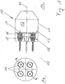
- a top view of a front panel 13 is schematically shown.
- Four premixed burners 14 are mounted on the front panel 13. It is remarkable that a central burner according to conventional can combustors does not exist.
- the four premixed burners 14 are symmetrically positioned on one perimeter in four identical 90° sectors of the front panel 13. All burners 14 have the same sense of swirl rotation, i.e. all burners generate either a clockwise swirl or an anti-clockwise swirl. In the embodiment, as shown in Fig. 5a , all burners 14 generate a clock-wise swirl flow 18.
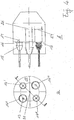
- Figures 5b, 5c and 5d represent embodiments, which do not form part of the invention, with two groups of burners 14', 14", 14"', 14"", a first group configured to generate a swirl flow in a first direction, e.g. a clockwise sense of flow, and a second group of burners to generate a swirl flow in opposite direction, e.g. an anti-clockwise sense of flow.
- adjacent burners 14 generate swirl flows 18 of opposite senses of rotation, whereas diagonally opposing burners 14'-14"', 14"-14”" have the same sense of rotation.
- the flows circulate in the same direction, the relative velocities of the adjacent swirls in this area are close to zero with low shear forces and low turbulences in this area 22 with the effect of a significantly reduced heat and mass transfer in this region.
- FIG. 5c shows additional configurations of burners with different swirl senses in a can combustor 10 with four burners 14', 14", 14"', 14"” according to the invention.
- Fig. 5c shows a configuration with diagonally opposing burners having different senses of swirl rotation and
- Fig. 5d shows a configuration with three burners 14', 14"', 14"" generating a clockwise swirl flow 18 and one burner 14" generating an anti-clockwise swirl flow 18.
- the can combustor according to the invention is disclosed in Fig. 2a .
- the four burners 14', 14", 14"', 14"" with one burner in each of the four 90° sectors are positioned on different radial distances from the centre of the can 10.
- the radial distance r 1 of at least one burner 14' differs from the radial distance r 2 , r 3 or r 4 of at least one other burner 14", 14'" or 14"", wherein the radial distances r 1 , r 2 , r 3 , r 4 are defined as the distances between the longitudinal axis 20 of the can 10 and the longitudinal axis 19 of the respective burner 14', 14", 14"', 14"".
- Fig. 2a shows an embodiment with four burners each of them positioned in the front panel 13 on a different distance from the central axis of the can combustor 10: r 1 ⁇ r 2 ⁇ r 3 ⁇ r 4 .
- Fig. 2b discloses a further aspect of the invention. At least one burner 14' of the four burners 14 with one burner in each of the four equal 90° sectors is positioned at a different azimuthal angle ⁇ 1 , ⁇ 2 , ⁇ 3 or ⁇ 4 in its respective 90° sector in relation to the position of at least one other burner 14", 14"' or 14"".
- FIGs 3a and 3b schematically show in another aspect a can combustor 10 with four burners 14, wherein at least one, up to all burners 14 are equipped with mixing tubes 16 of different length. From the side view of Fig. 3b can be seen that any burner 14', 14" and 14'" has a different mixing tube length 24 in relation to the mixing tube length of another burner 14. Different lengths 24 of the mixing tubes 16 of a premixed burner 14 effect different characteristic mixing times of the fuel/air mixture and consequently different durations of time between the moment, when the fuel is injected into the burner and that moment, when it reaches the flame front. Different mixing times are an effective means to decouple the interaction between the fuel supply and pressure parameters in the combustion zone and thus to reduce thermo-acoustic oscillations in the can combustor.
- FIG. 4a and 4b Another aspect of the inventive can combustor 10 is disclosed in Fig. 4a and 4b .
- the burners 14 within the can 10 differ in their dimension by being up-scaled or down-scaled from a nominal size.
- the burners 14', 14", 14"', 14"" differ in a diameter and/or a length of the swirl generator 15 and/or the mixing tube 16.
- Fig. 4a and 4b schematically show a can combustor 10 with four burners 14', 14", 14"', 14"". All burners 14 are positioned at the same distance from the central axis 20 of the can 10; the central axis 19 of every individual burner 14', 14", 14"', 14"” is arranged on the same perimeter circle 23.
- burners 14' and 14"' and burners 14" and 14" Two groups of burners can be identified: burners 14' and 14"' and burners 14" and 14"".
- the two groups differ in the dimensions of the length and the diameter of the swirl generator 15 and the mixing tube 16 and in the burner exit 17 diameter 27, wherein diametrically opposite burners 14' and 14"' or 14" and 14"" are equally dimensioned.
- At least one burner 14', 14", 14"' or 14"" is equipped with a smaller diameter than the other burners 14', 14", 14"', 14"" with the effect of less flow-through.
- This burner with the less flow-through can be operated with a higher pilot ratio with the effect of a reduction of the combustor dynamics and thus a stabilization of the combustion in the can 10.
- the individual burners 14', 14", 14"', 14"” generate swirls 18 of different intensity.
- this measure may be accompanied by any of the before-mentioned measures of different dimensioning of individual burner parts or of the creation of differing flow patterns of co- and counter-flow within the can combustor 10.
- Variations in the swirl intensity can be influenced by the dimension of the burner parts, but particularly differing intensities of the swirl flow (high swirl variants or low swirl variants) are realized by the dimension of the air inlet slots of the swirl generator 15 of an individual burner 14. The advantage is again in the higher inhomogeneity of the flow conditions in the combustor and hence in possible lower combustor dynamics.
- the can 10 according to Fig. 6a comprises a cylindrical housing 11 with a planar front panel 13 at its upstream end.
- the planar front panel 13 is arranged essentially orthogonally to the central axis 20 of the can combustor 10.
- Four burners 14 are attached to this front panel 13.
- the longitudinal axes 19 of all burners 14 are parallel to each other and are parallel to the central axis 20 of the can 10.
- Fig. 6a discloses as an alternative to arrange at least one burner 14' in a different direction.
- the longitudinal axis 19 of said at least one burner 14' or of more burners 14", 14"' and/or 14"" may be inclined up to ⁇ 10° relating to the central axis 20 of the can combustor 10.
- the respective burner exit(s) 17 is/are cut off flush with the front panel 13.
- the inclined burners possess an oval burner exit 17.
- the planar front panel 13 is replaced by a conical front panel 13, whereby the inclination angle of the conical front panel corresponds to the inclination angle of the burner axes 19.
- the plane of the burner exit 17 is parallel to the front panel 13.
- a can combustor 10 is equipped with a conically formed front panel 13 at its upstream end.
- Four burners 14 with parallel longitudinal axes 19 to each other and to the central axis 20 of the can 10 are attached to said front panel 13.
- Two options to attach the burners 14 to the front panel 13 are evident.
- the burners 14 can be fixed to front panel 13 in such a way that the burner exits 17 partly or completely protrude into the combustion zone 12 or alternatively the burner exits 17 are slanted to an ellipsoid outlet in such a way that they are flush against the conical front panel 13.
- the front panel 13 may be made of a segmented structure, based on a number four flat segments, preferably four segments, of an essentially triangular form.
Landscapes
- Engineering & Computer Science (AREA)
- Chemical & Material Sciences (AREA)
- Combustion & Propulsion (AREA)
- Mechanical Engineering (AREA)
- General Engineering & Computer Science (AREA)
- Gas Burners (AREA)
- Incineration Of Waste (AREA)
Priority Applications (8)
| Application Number | Priority Date | Filing Date | Title |
|---|---|---|---|
| EP13165488.1A EP2796789B1 (en) | 2013-04-26 | 2013-04-26 | Can combustor for a can-annular combustor arrangement in a gas turbine |
| CA2848898A CA2848898C (en) | 2013-04-26 | 2014-04-14 | Can combustor for a can-annular combustor arrangement in a gas turbine |
| IN1107DE2014 IN2014DE01107A (ja) | 2013-04-26 | 2014-04-23 | |
| RU2014116563/06A RU2581265C2 (ru) | 2013-04-26 | 2014-04-23 | Трубчатая камера сгорания для конструкции трубчато-кольцевой камеры сгорания в газовой турбине |
| US14/260,617 US10422535B2 (en) | 2013-04-26 | 2014-04-24 | Can combustor for a can-annular combustor arrangement in a gas turbine |
| KR1020140049781A KR101702854B1 (ko) | 2013-04-26 | 2014-04-25 | 가스 터빈의 캔 환형 연소기 배열을 위한 캔 연소기 |
| CN201410169977.6A CN104121601B (zh) | 2013-04-26 | 2014-04-25 | 用于燃气涡轮中的筒环形燃烧器布置的筒形燃烧器 |
| JP2014092325A JP2014215036A (ja) | 2013-04-26 | 2014-04-28 | ガスタービンにおける缶型環状燃焼器配列用の缶型燃焼器 |
Applications Claiming Priority (1)
| Application Number | Priority Date | Filing Date | Title |
|---|---|---|---|
| EP13165488.1A EP2796789B1 (en) | 2013-04-26 | 2013-04-26 | Can combustor for a can-annular combustor arrangement in a gas turbine |
Publications (2)
| Publication Number | Publication Date |
|---|---|
| EP2796789A1 EP2796789A1 (en) | 2014-10-29 |
| EP2796789B1 true EP2796789B1 (en) | 2017-03-01 |
Family
ID=48190758
Family Applications (1)
| Application Number | Title | Priority Date | Filing Date |
|---|---|---|---|
| EP13165488.1A Active EP2796789B1 (en) | 2013-04-26 | 2013-04-26 | Can combustor for a can-annular combustor arrangement in a gas turbine |
Country Status (8)
| Country | Link |
|---|---|
| US (1) | US10422535B2 (ja) |
| EP (1) | EP2796789B1 (ja) |
| JP (1) | JP2014215036A (ja) |
| KR (1) | KR101702854B1 (ja) |
| CN (1) | CN104121601B (ja) |
| CA (1) | CA2848898C (ja) |
| IN (1) | IN2014DE01107A (ja) |
| RU (1) | RU2581265C2 (ja) |
Families Citing this family (14)
| Publication number | Priority date | Publication date | Assignee | Title |
|---|---|---|---|---|
| US9939156B2 (en) * | 2013-06-05 | 2018-04-10 | Siemens Aktiengesellschaft | Asymmetric baseplate cooling with alternating swirl main burners |
| US10480823B2 (en) * | 2013-11-14 | 2019-11-19 | Lennox Industries Inc. | Multi-burner head assembly |
| EP3023696B1 (en) * | 2014-11-20 | 2019-08-28 | Ansaldo Energia Switzerland AG | Lobe lance for a gas turbine combustor |
| US10655541B2 (en) * | 2016-03-25 | 2020-05-19 | General Electric Company | Segmented annular combustion system |
| JP6822868B2 (ja) * | 2017-02-21 | 2021-01-27 | 三菱重工業株式会社 | 燃焼器及びガスタービン |
| US10584877B2 (en) * | 2017-04-28 | 2020-03-10 | DOOSAN Heavy Industries Construction Co., LTD | Device to correct flow non-uniformity within a combustion system |
| KR102063169B1 (ko) | 2017-07-04 | 2020-01-07 | 두산중공업 주식회사 | 연료 노즐 조립체와 이를 포함하는 연소기 및 가스 터빈 |
| JP6995696B2 (ja) * | 2018-05-28 | 2022-01-17 | 三菱重工業株式会社 | 燃料噴射装置及びガスタービン |
| US11286884B2 (en) * | 2018-12-12 | 2022-03-29 | General Electric Company | Combustion section and fuel injector assembly for a heat engine |
| KR102164622B1 (ko) * | 2019-06-11 | 2020-10-12 | 두산중공업 주식회사 | 공진주파수 회피형 멀티 튜브를 갖는 연소기 및 가스터빈 |
| JP2022171082A (ja) * | 2021-04-30 | 2022-11-11 | 東芝エネルギーシステムズ株式会社 | ガスタービン燃焼器構造体 |
| US20230003385A1 (en) * | 2021-07-02 | 2023-01-05 | General Electric Company | Premixer array |
| US20230204215A1 (en) * | 2021-12-29 | 2023-06-29 | General Electric Company | Fuel nozzle and swirler |
| KR102608433B1 (ko) * | 2022-02-09 | 2023-11-29 | 두산에너빌리티 주식회사 | 연소진동 저감을 위한 연소기용 노즐 및 이를 포함하는 가스 터빈 |
Family Cites Families (35)
| Publication number | Priority date | Publication date | Assignee | Title |
|---|---|---|---|---|
| SU352573A1 (ru) * | 1970-10-05 | 1983-06-23 | Pinchuk V V | Кольцева камера сгорани газотурбинного двигател |
| US3811274A (en) | 1972-08-30 | 1974-05-21 | United Aircraft Corp | Crossover tube construction |
| CH674561A5 (ja) | 1987-12-21 | 1990-06-15 | Bbc Brown Boveri & Cie | |
| CH687269A5 (de) * | 1993-04-08 | 1996-10-31 | Abb Management Ag | Gasturbogruppe. |
| CN2200120Y (zh) | 1994-07-16 | 1995-06-07 | 汤义勇 | 自动增压式合成燃料燃烧装置 |
| DE4435266A1 (de) | 1994-10-01 | 1996-04-04 | Abb Management Ag | Brenner |
| DE19547913A1 (de) * | 1995-12-21 | 1997-06-26 | Abb Research Ltd | Brenner für einen Wärmeerzeuger |
| DE19615910B4 (de) * | 1996-04-22 | 2006-09-14 | Alstom | Brenneranordnung |
| EP0925472B1 (de) * | 1996-09-16 | 2001-04-04 | Siemens Aktiengesellschaft | Verfahren zur unterdrückung von verbrennungsschwingungen und einrichtung zur verbrennung von brennstoff mit luft |
| GB2319078B (en) | 1996-11-08 | 1999-11-03 | Europ Gas Turbines Ltd | Combustor arrangement |
| SE9802707L (sv) | 1998-08-11 | 2000-02-12 | Abb Ab | Brännkammaranordning och förfarande för att reducera inverkan av akustiska trycksvängningar i en brännkammaranordning |
| US6769903B2 (en) * | 2000-06-15 | 2004-08-03 | Alstom Technology Ltd | Method for operating a burner and burner with stepped premix gas injection |
| US6438959B1 (en) * | 2000-12-28 | 2002-08-27 | General Electric Company | Combustion cap with integral air diffuser and related method |
| JP3872960B2 (ja) | 2001-02-28 | 2007-01-24 | 株式会社日立製作所 | ガスタ−ビン燃焼器 |
| JP4610800B2 (ja) | 2001-06-29 | 2011-01-12 | 三菱重工業株式会社 | ガスタービン燃焼器 |
| JP3986348B2 (ja) | 2001-06-29 | 2007-10-03 | 三菱重工業株式会社 | ガスタービン燃焼器の燃料供給ノズルおよびガスタービン燃焼器並びにガスタービン |
| EP1466124B1 (de) | 2002-01-14 | 2008-09-03 | ALSTOM Technology Ltd | Brenneranordnung für die ringförmige brennkammer einer gasturbine |
| JP4134311B2 (ja) | 2002-03-08 | 2008-08-20 | 独立行政法人 宇宙航空研究開発機構 | ガスタービン燃焼器 |
| US6968693B2 (en) * | 2003-09-22 | 2005-11-29 | General Electric Company | Method and apparatus for reducing gas turbine engine emissions |
| JP2006105534A (ja) | 2004-10-07 | 2006-04-20 | Niigata Power Systems Co Ltd | ガスタービン燃焼器 |
| JP2008519237A (ja) | 2004-11-03 | 2008-06-05 | アルストム テクノロジー リミテッド | 予混合バーナ |
| ATE479054T1 (de) * | 2005-03-09 | 2010-09-15 | Alstom Technology Ltd | Vormischbrenner zum erzeugen eines zündfähigen brennstoff-luftgemisches |
| CN101137869A (zh) * | 2005-03-09 | 2008-03-05 | 阿尔斯托姆科技有限公司 | 用于使燃烧室运转的预混燃烧器 |
| US7827797B2 (en) * | 2006-09-05 | 2010-11-09 | General Electric Company | Injection assembly for a combustor |
| US7886545B2 (en) * | 2007-04-27 | 2011-02-15 | General Electric Company | Methods and systems to facilitate reducing NOx emissions in combustion systems |
| FR2919348A1 (fr) * | 2007-07-23 | 2009-01-30 | Centre Nat Rech Scient | Dispositif d'injection d'un combustible ou d'un pre-melange combustible/comburant comprenant des moyens permettant un controle passif des instabilites de combustion |
| US8087228B2 (en) * | 2008-09-11 | 2012-01-03 | General Electric Company | Segmented combustor cap |
| US20100192578A1 (en) * | 2009-01-30 | 2010-08-05 | General Electric Company | System and method for suppressing combustion instability in a turbomachine |
| RU2506499C2 (ru) | 2009-11-09 | 2014-02-10 | Дженерал Электрик Компани | Топливные форсунки газовой турбины с противоположными направлениями завихрения |
| RU2534189C2 (ru) | 2010-02-16 | 2014-11-27 | Дженерал Электрик Компани | Камера сгорания для газовой турбины(варианты) и способ эксплуатации газовой турбины |
| EP2423591B1 (en) * | 2010-08-24 | 2018-10-31 | Ansaldo Energia IP UK Limited | Method for operating a combustion chamber |
| CH704829A2 (de) | 2011-04-08 | 2012-11-15 | Alstom Technology Ltd | Gasturbogruppe und zugehöriges Betriebsverfahren. |
| CH705179A1 (de) * | 2011-06-20 | 2012-12-31 | Alstom Technology Ltd | Verfahren zum Betrieb einer Verbrennungsvorrichtung sowie Verbrennungsvorrichtung zur Durchführung des Verfahrens. |
| US9310072B2 (en) * | 2012-07-06 | 2016-04-12 | Hamilton Sundstrand Corporation | Non-symmetric arrangement of fuel nozzles in a combustor |
| RU2561956C2 (ru) * | 2012-07-09 | 2015-09-10 | Альстом Текнолоджи Лтд | Газотурбинная система сгорания |
-
2013
- 2013-04-26 EP EP13165488.1A patent/EP2796789B1/en active Active
-
2014
- 2014-04-14 CA CA2848898A patent/CA2848898C/en not_active Expired - Fee Related
- 2014-04-23 IN IN1107DE2014 patent/IN2014DE01107A/en unknown
- 2014-04-23 RU RU2014116563/06A patent/RU2581265C2/ru active
- 2014-04-24 US US14/260,617 patent/US10422535B2/en active Active
- 2014-04-25 KR KR1020140049781A patent/KR101702854B1/ko active IP Right Grant
- 2014-04-25 CN CN201410169977.6A patent/CN104121601B/zh active Active
- 2014-04-28 JP JP2014092325A patent/JP2014215036A/ja active Pending
Also Published As
| Publication number | Publication date |
|---|---|
| CN104121601B (zh) | 2017-11-10 |
| KR20140128260A (ko) | 2014-11-05 |
| US10422535B2 (en) | 2019-09-24 |
| RU2014116563A (ru) | 2015-10-27 |
| CA2848898C (en) | 2016-10-04 |
| IN2014DE01107A (ja) | 2015-06-05 |
| US20140318135A1 (en) | 2014-10-30 |
| CA2848898A1 (en) | 2014-10-26 |
| CN104121601A (zh) | 2014-10-29 |
| KR101702854B1 (ko) | 2017-02-06 |
| JP2014215036A (ja) | 2014-11-17 |
| RU2581265C2 (ru) | 2016-04-20 |
| EP2796789A1 (en) | 2014-10-29 |
Similar Documents
| Publication | Publication Date | Title |
|---|---|---|
| EP2796789B1 (en) | Can combustor for a can-annular combustor arrangement in a gas turbine | |
| JP6335903B2 (ja) | 火炎シート燃焼器ドーム | |
| EP2685172B1 (en) | Can-annular gas turbine unit with staged premix-combustion | |
| EP1985926B1 (en) | Combustion equipment and combustion method | |
| EP1278013B1 (en) | Pilot burner, premixing combustor, and gas turbine | |
| US9518740B2 (en) | Axial swirler for a gas turbine burner | |
| US7950233B2 (en) | Combustor | |
| EP2407720B1 (en) | Flame tolerant secondary fuel nozzle | |
| EP1543272B1 (en) | Turbine engine fuel nozzle | |
| EP2873922B1 (en) | Gas turbine combustor | |
| EP0728989B1 (en) | Gas turbine engine combustor | |
| KR20130041207A (ko) | 가스 터빈 연소기 및 가스 터빈 | |
| US11175043B2 (en) | Burner assembly, combustor, and gas turbine | |
| US20170009993A1 (en) | Cavity staging in a combustor | |
| CN105318357B (zh) | 用于燃气涡轮发动机燃烧器导流罩的圆锥-平坦隔热罩 | |
| JP2004162959A (ja) | アニュラ型渦巻き拡散火炎燃焼器 | |
| JP2003207131A (ja) | ガスタービンのバーナ用の改良された液体燃料インジェクタ | |
| JP2016023916A (ja) | ガスタービン燃焼器 | |
| US9441543B2 (en) | Gas turbine combustor including a premixing chamber having an inner diameter enlarging portion | |
| KR102292893B1 (ko) | 혼합율을 향상시킬 수 있는 수소가스 연소장치 | |
| KR102292891B1 (ko) | 예혼합 성능을 향상시킬 수 있는 확산 연소형 수소 연소장치 | |
| EP2735798B1 (en) | Gas turbine combustor |
Legal Events
| Date | Code | Title | Description |
|---|---|---|---|
| PUAI | Public reference made under article 153(3) epc to a published international application that has entered the european phase |
Free format text: ORIGINAL CODE: 0009012 |
|
| 17P | Request for examination filed |
Effective date: 20130426 |
|
| AK | Designated contracting states |
Kind code of ref document: A1 Designated state(s): AL AT BE BG CH CY CZ DE DK EE ES FI FR GB GR HR HU IE IS IT LI LT LU LV MC MK MT NL NO PL PT RO RS SE SI SK SM TR |
|
| AX | Request for extension of the european patent |
Extension state: BA ME |
|
| R17P | Request for examination filed (corrected) |
Effective date: 20150428 |
|
| RBV | Designated contracting states (corrected) |
Designated state(s): AL AT BE BG CH CY CZ DE DK EE ES FI FR GB GR HR HU IE IS IT LI LT LU LV MC MK MT NL NO PL PT RO RS SE SI SK SM TR |
|
| GRAP | Despatch of communication of intention to grant a patent |
Free format text: ORIGINAL CODE: EPIDOSNIGR1 |
|
| INTG | Intention to grant announced |
Effective date: 20151127 |
|
| RAP1 | Party data changed (applicant data changed or rights of an application transferred) |
Owner name: GENERAL ELECTRIC TECHNOLOGY GMBH |
|
| GRAA | (expected) grant |
Free format text: ORIGINAL CODE: 0009210 |
|
| GRAS | Grant fee paid |
Free format text: ORIGINAL CODE: EPIDOSNIGR3 |
|
| AK | Designated contracting states |
Kind code of ref document: B1 Designated state(s): AL AT BE BG CH CY CZ DE DK EE ES FI FR GB GR HR HU IE IS IT LI LT LU LV MC MK MT NL NO PL PT RO RS SE SI SK SM TR |
|
| REG | Reference to a national code |
Ref country code: GB Ref legal event code: FG4D |
|
| REG | Reference to a national code |
Ref country code: CH Ref legal event code: EP Ref country code: AT Ref legal event code: REF Ref document number: 871827 Country of ref document: AT Kind code of ref document: T Effective date: 20170315 |
|
| REG | Reference to a national code |
Ref country code: IE Ref legal event code: FG4D |
|
| REG | Reference to a national code |
Ref country code: DE Ref legal event code: R096 Ref document number: 602013017859 Country of ref document: DE |
|
| REG | Reference to a national code |
Ref country code: FR Ref legal event code: PLFP Year of fee payment: 5 |
|
| RAP2 | Party data changed (patent owner data changed or rights of a patent transferred) |
Owner name: ANSALDO ENERGIA SWITZERLAND AG |
|
| REG | Reference to a national code |
Ref country code: SE Ref legal event code: TRGR |
|
| REG | Reference to a national code |
Ref country code: NL Ref legal event code: MP Effective date: 20170301 |
|
| REG | Reference to a national code |
Ref country code: LT Ref legal event code: MG4D |
|
| REG | Reference to a national code |
Ref country code: AT Ref legal event code: MK05 Ref document number: 871827 Country of ref document: AT Kind code of ref document: T Effective date: 20170301 |
|
| PG25 | Lapsed in a contracting state [announced via postgrant information from national office to epo] |
Ref country code: LT Free format text: LAPSE BECAUSE OF FAILURE TO SUBMIT A TRANSLATION OF THE DESCRIPTION OR TO PAY THE FEE WITHIN THE PRESCRIBED TIME-LIMIT Effective date: 20170301 Ref country code: GR Free format text: LAPSE BECAUSE OF FAILURE TO SUBMIT A TRANSLATION OF THE DESCRIPTION OR TO PAY THE FEE WITHIN THE PRESCRIBED TIME-LIMIT Effective date: 20170602 Ref country code: NO Free format text: LAPSE BECAUSE OF FAILURE TO SUBMIT A TRANSLATION OF THE DESCRIPTION OR TO PAY THE FEE WITHIN THE PRESCRIBED TIME-LIMIT Effective date: 20170601 Ref country code: HR Free format text: LAPSE BECAUSE OF FAILURE TO SUBMIT A TRANSLATION OF THE DESCRIPTION OR TO PAY THE FEE WITHIN THE PRESCRIBED TIME-LIMIT Effective date: 20170301 Ref country code: FI Free format text: LAPSE BECAUSE OF FAILURE TO SUBMIT A TRANSLATION OF THE DESCRIPTION OR TO PAY THE FEE WITHIN THE PRESCRIBED TIME-LIMIT Effective date: 20170301 |
|
| PGFP | Annual fee paid to national office [announced via postgrant information from national office to epo] |
Ref country code: CH Payment date: 20170620 Year of fee payment: 5 |
|
| PG25 | Lapsed in a contracting state [announced via postgrant information from national office to epo] |
Ref country code: LV Free format text: LAPSE BECAUSE OF FAILURE TO SUBMIT A TRANSLATION OF THE DESCRIPTION OR TO PAY THE FEE WITHIN THE PRESCRIBED TIME-LIMIT Effective date: 20170301 Ref country code: AT Free format text: LAPSE BECAUSE OF FAILURE TO SUBMIT A TRANSLATION OF THE DESCRIPTION OR TO PAY THE FEE WITHIN THE PRESCRIBED TIME-LIMIT Effective date: 20170301 Ref country code: BG Free format text: LAPSE BECAUSE OF FAILURE TO SUBMIT A TRANSLATION OF THE DESCRIPTION OR TO PAY THE FEE WITHIN THE PRESCRIBED TIME-LIMIT Effective date: 20170601 Ref country code: ES Free format text: LAPSE BECAUSE OF FAILURE TO SUBMIT A TRANSLATION OF THE DESCRIPTION OR TO PAY THE FEE WITHIN THE PRESCRIBED TIME-LIMIT Effective date: 20170301 Ref country code: RS Free format text: LAPSE BECAUSE OF FAILURE TO SUBMIT A TRANSLATION OF THE DESCRIPTION OR TO PAY THE FEE WITHIN THE PRESCRIBED TIME-LIMIT Effective date: 20170301 |
|
| PG25 | Lapsed in a contracting state [announced via postgrant information from national office to epo] |
Ref country code: NL Free format text: LAPSE BECAUSE OF FAILURE TO SUBMIT A TRANSLATION OF THE DESCRIPTION OR TO PAY THE FEE WITHIN THE PRESCRIBED TIME-LIMIT Effective date: 20170301 |
|
| PG25 | Lapsed in a contracting state [announced via postgrant information from national office to epo] |
Ref country code: EE Free format text: LAPSE BECAUSE OF FAILURE TO SUBMIT A TRANSLATION OF THE DESCRIPTION OR TO PAY THE FEE WITHIN THE PRESCRIBED TIME-LIMIT Effective date: 20170301 Ref country code: SK Free format text: LAPSE BECAUSE OF FAILURE TO SUBMIT A TRANSLATION OF THE DESCRIPTION OR TO PAY THE FEE WITHIN THE PRESCRIBED TIME-LIMIT Effective date: 20170301 Ref country code: CZ Free format text: LAPSE BECAUSE OF FAILURE TO SUBMIT A TRANSLATION OF THE DESCRIPTION OR TO PAY THE FEE WITHIN THE PRESCRIBED TIME-LIMIT Effective date: 20170301 Ref country code: RO Free format text: LAPSE BECAUSE OF FAILURE TO SUBMIT A TRANSLATION OF THE DESCRIPTION OR TO PAY THE FEE WITHIN THE PRESCRIBED TIME-LIMIT Effective date: 20170301 |
|
| PG25 | Lapsed in a contracting state [announced via postgrant information from national office to epo] |
Ref country code: IS Free format text: LAPSE BECAUSE OF FAILURE TO SUBMIT A TRANSLATION OF THE DESCRIPTION OR TO PAY THE FEE WITHIN THE PRESCRIBED TIME-LIMIT Effective date: 20170701 Ref country code: PT Free format text: LAPSE BECAUSE OF FAILURE TO SUBMIT A TRANSLATION OF THE DESCRIPTION OR TO PAY THE FEE WITHIN THE PRESCRIBED TIME-LIMIT Effective date: 20170703 Ref country code: PL Free format text: LAPSE BECAUSE OF FAILURE TO SUBMIT A TRANSLATION OF THE DESCRIPTION OR TO PAY THE FEE WITHIN THE PRESCRIBED TIME-LIMIT Effective date: 20170301 Ref country code: SM Free format text: LAPSE BECAUSE OF FAILURE TO SUBMIT A TRANSLATION OF THE DESCRIPTION OR TO PAY THE FEE WITHIN THE PRESCRIBED TIME-LIMIT Effective date: 20170301 |
|
| PGFP | Annual fee paid to national office [announced via postgrant information from national office to epo] |
Ref country code: SE Payment date: 20170419 Year of fee payment: 5 |
|
| REG | Reference to a national code |
Ref country code: CH Ref legal event code: PL |
|
| REG | Reference to a national code |
Ref country code: DE Ref legal event code: R097 Ref document number: 602013017859 Country of ref document: DE |
|
| PLBE | No opposition filed within time limit |
Free format text: ORIGINAL CODE: 0009261 |
|
| STAA | Information on the status of an ep patent application or granted ep patent |
Free format text: STATUS: NO OPPOSITION FILED WITHIN TIME LIMIT |
|
| REG | Reference to a national code |
Ref country code: IE Ref legal event code: MM4A |
|
| PG25 | Lapsed in a contracting state [announced via postgrant information from national office to epo] |
Ref country code: MC Free format text: LAPSE BECAUSE OF FAILURE TO SUBMIT A TRANSLATION OF THE DESCRIPTION OR TO PAY THE FEE WITHIN THE PRESCRIBED TIME-LIMIT Effective date: 20170301 Ref country code: DK Free format text: LAPSE BECAUSE OF FAILURE TO SUBMIT A TRANSLATION OF THE DESCRIPTION OR TO PAY THE FEE WITHIN THE PRESCRIBED TIME-LIMIT Effective date: 20170301 |
|
| 26N | No opposition filed |
Effective date: 20171204 |
|
| PG25 | Lapsed in a contracting state [announced via postgrant information from national office to epo] |
Ref country code: CH Free format text: LAPSE BECAUSE OF NON-PAYMENT OF DUE FEES Effective date: 20170430 Ref country code: LU Free format text: LAPSE BECAUSE OF NON-PAYMENT OF DUE FEES Effective date: 20170426 Ref country code: SI Free format text: LAPSE BECAUSE OF FAILURE TO SUBMIT A TRANSLATION OF THE DESCRIPTION OR TO PAY THE FEE WITHIN THE PRESCRIBED TIME-LIMIT Effective date: 20170301 Ref country code: LI Free format text: LAPSE BECAUSE OF NON-PAYMENT OF DUE FEES Effective date: 20170430 |
|
| REG | Reference to a national code |
Ref country code: BE Ref legal event code: MM Effective date: 20170430 |
|
| PG25 | Lapsed in a contracting state [announced via postgrant information from national office to epo] |
Ref country code: IE Free format text: LAPSE BECAUSE OF NON-PAYMENT OF DUE FEES Effective date: 20170426 |
|
| PG25 | Lapsed in a contracting state [announced via postgrant information from national office to epo] |
Ref country code: BE Free format text: LAPSE BECAUSE OF NON-PAYMENT OF DUE FEES Effective date: 20170430 |
|
| PG25 | Lapsed in a contracting state [announced via postgrant information from national office to epo] |
Ref country code: MT Free format text: LAPSE BECAUSE OF NON-PAYMENT OF DUE FEES Effective date: 20170426 |
|
| REG | Reference to a national code |
Ref country code: SE Ref legal event code: EUG |
|
| PG25 | Lapsed in a contracting state [announced via postgrant information from national office to epo] |
Ref country code: SE Free format text: LAPSE BECAUSE OF NON-PAYMENT OF DUE FEES Effective date: 20180427 |
|
| PG25 | Lapsed in a contracting state [announced via postgrant information from national office to epo] |
Ref country code: FR Free format text: LAPSE BECAUSE OF NON-PAYMENT OF DUE FEES Effective date: 20180430 |
|
| PG25 | Lapsed in a contracting state [announced via postgrant information from national office to epo] |
Ref country code: HU Free format text: LAPSE BECAUSE OF FAILURE TO SUBMIT A TRANSLATION OF THE DESCRIPTION OR TO PAY THE FEE WITHIN THE PRESCRIBED TIME-LIMIT; INVALID AB INITIO Effective date: 20130426 |
|
| PG25 | Lapsed in a contracting state [announced via postgrant information from national office to epo] |
Ref country code: CY Free format text: LAPSE BECAUSE OF FAILURE TO SUBMIT A TRANSLATION OF THE DESCRIPTION OR TO PAY THE FEE WITHIN THE PRESCRIBED TIME-LIMIT Effective date: 20170301 |
|
| PG25 | Lapsed in a contracting state [announced via postgrant information from national office to epo] |
Ref country code: MK Free format text: LAPSE BECAUSE OF FAILURE TO SUBMIT A TRANSLATION OF THE DESCRIPTION OR TO PAY THE FEE WITHIN THE PRESCRIBED TIME-LIMIT Effective date: 20170301 |
|
| PG25 | Lapsed in a contracting state [announced via postgrant information from national office to epo] |
Ref country code: TR Free format text: LAPSE BECAUSE OF FAILURE TO SUBMIT A TRANSLATION OF THE DESCRIPTION OR TO PAY THE FEE WITHIN THE PRESCRIBED TIME-LIMIT Effective date: 20170301 |
|
| PG25 | Lapsed in a contracting state [announced via postgrant information from national office to epo] |
Ref country code: AL Free format text: LAPSE BECAUSE OF FAILURE TO SUBMIT A TRANSLATION OF THE DESCRIPTION OR TO PAY THE FEE WITHIN THE PRESCRIBED TIME-LIMIT Effective date: 20170301 |
|
| PGFP | Annual fee paid to national office [announced via postgrant information from national office to epo] |
Ref country code: IT Payment date: 20230825 Year of fee payment: 11 Ref country code: GB Payment date: 20230822 Year of fee payment: 11 |
|
| PGFP | Annual fee paid to national office [announced via postgrant information from national office to epo] |
Ref country code: DE Payment date: 20230821 Year of fee payment: 11 |