EP2795239B1 - Appareil 3d de mesure a palpeur - Google Patents
Appareil 3d de mesure a palpeur Download PDFInfo
- Publication number
- EP2795239B1 EP2795239B1 EP12812906.1A EP12812906A EP2795239B1 EP 2795239 B1 EP2795239 B1 EP 2795239B1 EP 12812906 A EP12812906 A EP 12812906A EP 2795239 B1 EP2795239 B1 EP 2795239B1
- Authority
- EP
- European Patent Office
- Prior art keywords
- probe
- measuring
- housing
- lever
- arm
- Prior art date
- Legal status (The legal status is an assumption and is not a legal conclusion. Google has not performed a legal analysis and makes no representation as to the accuracy of the status listed.)
- Active
Links
- 239000000523 sample Substances 0.000 claims description 169
- 230000008878 coupling Effects 0.000 claims description 51
- 238000010168 coupling process Methods 0.000 claims description 51
- 238000005859 coupling reaction Methods 0.000 claims description 51
- 241000309551 Arthraxon hispidus Species 0.000 claims description 24
- 238000006073 displacement reaction Methods 0.000 claims description 15
- 230000005540 biological transmission Effects 0.000 claims description 7
- 230000007246 mechanism Effects 0.000 claims description 4
- 238000010276 construction Methods 0.000 claims description 2
- 230000035939 shock Effects 0.000 claims description 2
- 230000000717 retained effect Effects 0.000 claims 1
- 241001422033 Thestylus Species 0.000 description 13
- 238000013461 design Methods 0.000 description 2
- 238000005259 measurement Methods 0.000 description 2
- 238000012545 processing Methods 0.000 description 2
- 230000007704 transition Effects 0.000 description 2
- 238000006243 chemical reaction Methods 0.000 description 1
- 230000007423 decrease Effects 0.000 description 1
- 238000001514 detection method Methods 0.000 description 1
- 238000011161 development Methods 0.000 description 1
- 239000011521 glass Substances 0.000 description 1
- 230000009931 harmful effect Effects 0.000 description 1
- 230000001939 inductive effect Effects 0.000 description 1
- 238000012986 modification Methods 0.000 description 1
- 230000004048 modification Effects 0.000 description 1
- 238000013519 translation Methods 0.000 description 1
Images


Classifications
-
- G—PHYSICS
- G01—MEASURING; TESTING
- G01B—MEASURING LENGTH, THICKNESS OR SIMILAR LINEAR DIMENSIONS; MEASURING ANGLES; MEASURING AREAS; MEASURING IRREGULARITIES OF SURFACES OR CONTOURS
- G01B5/00—Measuring arrangements characterised by the use of mechanical techniques
- G01B5/004—Measuring arrangements characterised by the use of mechanical techniques for measuring coordinates of points
- G01B5/008—Measuring arrangements characterised by the use of mechanical techniques for measuring coordinates of points using coordinate measuring machines
- G01B5/012—Contact-making feeler heads therefor
Definitions
- the present invention relates generally to a 3D touch measuring device and in particular a 3D touch measuring device which is particularly suitable for probing workpieces in the direction of a measuring axis and transversely to the measuring axis.
- Such 3D stylus measuring devices generally have a stylus arm protruding from the housing and carrying a stylus tip, which can be displaced relative to the housing in the direction of a measuring axis and pivoted on all sides about the measuring axis, and a measuring device for detecting the deflection of the stylus arm.
- Conventional mechanical dial indicators are usually used for this purpose. These usually have a round scale and an analog display, the longitudinal movement of a measuring pin being transmitted to a rotatable pointer of the dial gauge display by means of a rack attached to an inner end of the measuring pin and a gear drive driven by the rack. Dial gauges with a digital display are also used.
- the 3D probe measuring devices can e.g. can be used to set the zero point of a numerically controlled machine tool in relation to the workpiece to be machined.
- the stylus measuring device is clamped in a machine tool spindle and its stylus tip is moved to a reference surface of the workpiece.
- the probe arm is then pushed away from the workpiece until the pointer of the dial gauge reaches its zero position.
- DE 195 02 840 C2 describes a generic multi-coordinate probe measuring device which has a housing, a housing that is displaceable in the direction of a measuring axis relative to the housing and, by means of a universal joint, is guided on the housing so that it can pivot on all sides about a pivot point located on the measuring axis, resiliently pretensioned in a rest position probe lever with a probe arm protruding from the housing and a coupling arm projecting away from the probe arm relative to the pivot point opposite to the probe arm; the housing is mounted and guided displaceably, and has a measuring device that detects the position of the coupling piece in relation to the housing.
- the probe arm carries a probe tip at its free end and is fastened at its other end in the coupling arm.
- the other free end of the coupling arm remote from the pivot point of the probe tip, has an outer control surface which is rotationally symmetrical to the measuring axis in the rest position of the probe lever and has a circular segment-shaped generating line, the center of which is eccentric to the rotational symmetry axis.
- This outer control surface interacts with an inner control surface, which is formed at the end of the coupling piece axially remote from the pivot point in the form of a truncated conical surface with a straight generating line, in such a way that the coupling arm both when moving the probe arm in the direction of the measuring axis and when deflecting the Probe arm takes along the coupling piece in the direction of the measuring axis around the pivot point.
- a mechanical dial gauge is provided as a measuring device, which is attached to the side of the housing and is coupled to the coupling piece via a coupling pin running transversely to the measuring axis and movable in the direction of the measuring axis.
- the coupling pin protrudes into the dial gauge through an elongated slot in an intermediate wall of the probe and acts on a measuring and display mechanism of the dial gauge.
- the touch measuring device is held in a machine tool or a measuring device or the like by means of a tapered shaft.
- the coupling arm takes the coupling piece with it, which in turn sets the mechanical dial indicator.
- the coupling arm pivots around the pivot point defined by the ball joint, with the control surfaces sliding against one another converting the pivoting movement of the probe lever into an axial movement of the coupling sleeve, which is recorded by the dial gauge and used as a measured value for the radial distance of the Stylus tip is used by the measuring axis.
- the radial distance of the probe tip from the measuring axis is converted into the axial adjustment stroke of the coupling piece caused by the pivoting movement of the probe lever in a linearly proportional 1: 1 ratio.
- the previously known touch measuring device is suitable for the applications provided here.
- it has a relatively complex, expensive structure with a large number of intricately designed individual components that are operatively connected to one another. These each require a relatively large amount of space and make the feeler gauge relatively bulky.
- the structural volume is greatly increased by the coupling sleeve surrounding the probe lever around the circumference.
- a separate guide must be provided for the coupling sleeve in addition to the guides for the feeler lever and the mechanism of the dial indicator.
- the dial gauge attached to the side of the housing of the touch measuring device which is arranged radially further out from the coupling sleeve and is coupled to this via the coupling pin running transversely to the measuring axis, increases the structural volume and the interference contour of the touch measuring device all the more.
- From the DE 37 01 730 C2 is a similar multi-coordinate probe with a housing that can be clamped into a tool spindle, over which a probe arm with a probe ball protrudes at the free end, which is axially displaceable in the housing and pivoted on all sides up to a predetermined maximum angle and whose deflection can be converted into a linear movement of a slide by means of a conversion system, which is arranged centrally in the housing to the measuring axis and guided displaceably against the force of a return spring and on which the inner end of the probe arm is pivotably supported on all sides.
- the slide At its end remote from the stylus ball, the slide carries a transverse arm which protrudes outward through an axial slot in the housing of the stylus measuring device and is connected to an actuator of a dial gauge which is attached to the outside of the housing of the stylus measuring device.
- the actuating element can be the measuring pin of the mechanical dial gauge that is led out of the housing of the dial gauge.
- This measuring probe structure also has a high number of components and a relatively large structural volume, in particular in the direction transverse to the measuring axis.
- DE 103 34 503 A1 describes a 3D stylus measuring device with a stylus arm carrying a stylus tip, which is displaceable along a measuring axis relative to a housing and can be pivoted on all sides by means of a first universal joint around the measuring axis, a transmission system that allows the stylus tip to be displaced axially in the housing stored slide transmits, and a display device for displaying a size indicative of the deflection of the probe tip.
- the transmission system contains a tactile lever supported on the housing side so that it can pivot on all sides via the first universal joint, which is connected at one end to the tactile arm and which is connected at its other end via a second universal joint to the slide, which is connected to an electronic and / or mechanical associated with the display device Actuating device cooperates.
- GB 804 534 A describes a measuring device in the form of a dial gauge, which has a measuring pin, which is displaceable in the direction of a longitudinal axis of the dial gauge, and one with the measuring pin having coupled rack-and-pinion combination for transmitting the longitudinal movement of the measuring pin into a rotary movement of a rotatable pointer of the dial indicator display.
- the rack is formed by a toothing that is formed on an actuating element mounted displaceably on the measuring pin and meshes with a rack pinion that is coupled to a pointer of the dial gauge.
- JP 07-043 101 A describes a button with a housing, a pivotably and displaceably mounted probe arm, a probe lever connected to the probe arm, the probe lever carrying a disk-shaped base which is coupled to a disc-shaped end of a displaceably mounted cylindrical coupling element in such a way that a pivoting movement of the probe lever with the Probe arm is implemented in a displacement of the coupling element.
- the coupling element is coupled to a dial gauge arranged in the housing, a measuring pin of the dial indicator being arranged concentrically to the measuring axis, aligned with the coupling element and loosely in contact with the coupling element.
- DE 1 538 459 A describes an electrical button for control sequences with a shaft for a feeler pin head attached to a cardan joint so that it can be deflected, the shaft acting via a universal joint on a longitudinally displaceable slider which, via a collar, actuates a group of contacts arranged concentrically around it in a ring.
- a stem of the probe is attached to the collar, a spring biasing the stem with the stem outwards in the direction of the feeler pin head.
- an external dial gauge is attached, the measuring pin of which protrudes into the probe housing, runs concentrically to the measuring or longitudinal axis of the probe and is supported against the stem of the probe in order to read the To enable deflection of the contacts.
- the inventive 3D probe measuring device in particular for probing workpieces in machine tools, e.g. for setting the zero point of a numerically controlled machine tool or for positioning tasks, has a preferably elongated housing that defines a longitudinal direction, a probe arm protruding from the housing and carrying a probe tip that is relatively the housing is displaceable in the direction of a measuring axis running in the longitudinal direction and is pivotable on all sides by means of a first universal joint around the measuring axis, a feeler lever connected to the probe arm, which forms the first universal joint, and a measuring device for detecting the displacement and / or pivoting of the probe arm characteristic size.
- the feeler lever has an end that faces the feeler arm and is firmly connected to the latter, on which a joint head is formed which has an outer control surface which is rotatably supported on an inner control surface of the housing to form the first universal joint for pivoting the feeler arm, and an end facing away from the probe arm on which a further control surface is provided for a second universal joint.
- the measuring device has an elongated toothed rack of a toothed wheel drive of the measuring device, which is aligned and displaceably mounted along the measuring axis and which is mounted via the second universal joint is effectively coupled to the feeler lever.
- the rack carries a jointly displaceable coupling element which is a separate component from the rack, which is detachably attached to a front end of the rack, or which is integrally formed on the rack.
- the coupling element has a control surface of the second universal joint which cooperates with the further control surface in order to couple the feeler lever to the rack.
- the probe arm, the probe lever and the toothed rack with the coupling element are arranged centrically to the measuring axis in the rest state.
- both the probe arm, the probe lever and the toothed rack of the measuring device or dial gauge with the coupling element attached or molded to it in the rest state, i.e. in the non-deflected initial state, are all centered in the measuring axis, i.e. with their longitudinal alignment along the measuring axis one behind the other arranged. If a toothing of the rack is not taken into account, they are also designed to be rotationally symmetrical to the measuring axis. Since the measuring axis coincides with the longitudinal axis or “quasi-symmetry axis” of the housing, the central arrangement according to the invention enables an extremely slim shape of the housing and extremely small transverse dimensions of the measuring probe.
- the structure and the functionality of the measuring probe are also greatly simplified and the number of components is reduced. This also benefits the functional reliability and service life of the probe. This is achieved above all by moving the toothed rack of the dial indicator into the measuring axis so that there is no axial offset between the toothed rack and the measuring axis.
- the dial indicator is located deep in the housing, close to the measuring axis.
- the measuring probe does not have any cross-connection elements, such as those used with conventional measuring probes for coupling to the toothed rack of the dial gauge.
- Housing of the stylus measuring device is constructed in several parts and has at least one first housing section, which accommodates the measuring device and a display device for displaying the values detected by the measuring device, a housing cover which is preferably detachably fastened to a front end region of the housing adjacent to the stylus tip, in particular by screwing and a second housing section which is arranged between the first housing section and the housing cover and which receives a guide sleeve for the longitudinally displaceable guidance of the probe lever along the measuring axis.
- the first and the second housing section are preferably formed by separate housing parts which are connected to one another, in particular screwed together. In principle, however, they can also be formed in one piece with one another. Alternatively, the guide sleeve could also be designed in one piece with the second housing section.
- the guide sleeve is provided for guiding the feeler lever during its longitudinal displacement along the measuring axis.
- it has a cylindrical inner surface which receives and guides an outer surface with little play, in particular on the joint head of the feeler lever.
- the guide sleeve has a constriction which is formed in the inner surface of the guide sleeve at a distance from an end face of the guide sleeve facing the probe tip and which forms an end stop to limit the axial movement of the probe lever in the guide sleeve.
- the cylindrical inner surface of the guide sleeve protects the components of the probe measuring device, in particular the measuring device, as a lateral stop in the event of transverse joints, while the constriction as an axial stop protects in particular against overloading in the event of axial joints.
- the inner control surface of the first universal joint is on the housing cover educated. This makes it easier to assemble the probe.
- the inner control surface could, however, also be provided on other housing sections or parts or also on a separate element fastened in the housing.
- the inner control surface of the first universal joint preferably has a frustoconical shape that is rotationally symmetrical about the measuring axis and has a straight generating line.
- the outer control surface of the first universal joint that interacts therewith can then preferably have a convex shape that is rotationally symmetrical to the measuring axis and has a circular segment-shaped generating line.
- the joint head of the feeler lever is thus at least partially spherical. This creates a simply designed, reliable universal joint which enables a high degree of accuracy when converting a pivoting movement of the probe arm into a linear movement of the rack and enables precise detection of the probe arm deflection.
- the housing cover forms part of an exchangeable structural unit which has the feeler arm, the feeler lever and the guide sleeve for the longitudinally displaceable guidance of the feeler lever along the measuring axis.
- the preassembled unit enables quick and easy replacement and quick reuse of the stylus measuring device if the stylus arm is damaged, for example, by an impact against an obstacle.
- the feeler arm itself is held exchangeably on the feeler lever, in particular on the end having the joint head of the first universal joint, for example screwed on.
- a grub screw connects, for example, the joint head of the feeler lever to the inner end of the feeler arm.
- the probe arm can then be replaced quickly and easily in the event of damage, wear, etc.
- the feeler arm can also be made in one piece with the feeler lever be trained.
- the feeler arm can have a radial constriction at a point near the feeler lever, which results in a predetermined breakage of the feeler arm at this point in the event of a predetermined overload. This means that other components of the touch measuring device can be spared the harmful effects of the impacts.
- the feeler lever has an articulated head which has an at least partially spherical area defining the outer control surface, which extends around an axis perpendicular to the measuring axis over an angle of slightly more than 180 °, and then follows having tapering further area extending to the spherical area.
- the diameter of the tapered area continuously decreases in the direction away from the spherical area towards the end facing away from the probe arm.
- the tapering area can, for example, be designed to be rotationally symmetrical to the measuring axis and frustoconical with a straight generating line.
- the joint head then has the largest diameter at the transition from the spherical area to the tapering area and an extremely small contact point with which it is in contact with the inside of the guide sleeve. This essentially results in a point bearing and guidance of the joint head in the guide sleeve, which ensures good sliding properties of the feeler lever in the guide sleeve with little friction.
- the feeler lever also has, in its end face opposite the spherical joint head, a conical surface that is rotationally symmetrical around the measuring axis and widening towards the rack with a straight or slightly curved generatrix that forms the inner control surface of the second universal joint forms.
- This inner control surface then interacts with a preferably spherical outer control surface of the second universal joint in order to convert a pivoting of the feeler lever into an axial displacement of the rack.
- the coupling element is provided, which couples the feeler lever with the rack.
- the feeler lever acts directly on the coupling element, and the coupling element acts axially on the rack.
- the coupling element can have a spherical end that defines the outer control surface of the second universal joint and on which, for example, the frontal conical surface of the ball lever is rotatably supported.
- the coupling element is also space-saving and is arranged centrically to the measuring axis in the rest position.
- the coupling element can be a component produced separately from the toothed rack, which is detachably attached, preferably screwed, to a front end of the toothed rack.
- the coupling element can also be formed integrally on the toothed rack in one piece.
- the spherical outer control surface of the second universal joint for example, has to be molded directly onto a front end of the rack (or a measuring pin connected to it).
- a conventional mechanical dial gauge can be used as a measuring device for detecting the longitudinal and / or transverse deflection of the probe arm, which has a mechanical system for transferring the straight path of the rack, for example to a circular path of a pointer on a dial of a display or for implementation in has digital output on a numeric display.
- the dial indicator has a gear drive with a rack pinion that meshes with the rack in order to convert the straight-line movement of the rack into a circular movement of the rack pinion, and a transmission gear train that converts the short rotation of the rack pinion into a long rotary movement, for example .
- a pointer of the display device converts.
- Further gears can be provided for further translation stages.
- the rack is preferably slidably guided along the measuring axis by sliding bearings.
- the maximum axial displacement path specified by the second universal joint is smaller than the maximum stroke length of the rack, which is or is determined, for example, by the measuring range limit of the measuring device.
- the probe measuring device has further components, such as means to prevent the probe lever and the rack from rotating about the measuring axis, a return spring that biases the probe lever and probe arm into the rest position, a clamping shaft for clamping in a machine tool spindle on the of the end of the housing facing away from the probe tip and preferably a device for adjusting and centering the clamping shaft with respect to the measuring axis.
- the central arrangement of the main components of the 3-D probe measuring device according to the invention results in an extremely compact multi-coordinate measuring probe which has a simple, clear, robust structure and enables easy handling and a long service life.
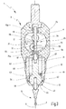
- Fig. 1 a simplified representation of a 3-D touch measuring device is illustrated, which can be used, for example, for setting the zero point of a numerically controlled machine tool in relation to the workpiece to be machined or for positioning tasks for positioning a workpiece in relation to a measuring or processing machine.
- the touch measuring device enables workpieces to be probed both in the longitudinal direction of the touch measuring device, as shown in FIG Fig. 1 is indicated by a double arrow 2, as well as in each direction perpendicular to the longitudinal direction 2.
- the 3-D probe measuring device 1 has a housing 3 with a display device 4 provided in the area of its housing side facing the viewer, a probe arm 6 protruding from the housing 3, which carries a spherical probe tip 7 at its free end for probing a workpiece, and a on the longitudinal end of the housing 3 opposite the probe tip 7, for clamping the probe measuring device, for example in the tool holder of the machine tool.
- the probe arm 6 can be deflected axially along the measuring axis 9 coinciding with the longitudinal axis 2 of the probe measuring device 1 and / or in any radial direction transversely to the measuring axis 9, which enables three-dimensional scanning of a workpiece.
- FIG. 1 The illustrated 3-D touch probe is shown in more detail in the Figures 2 and 3 illustrates the longitudinal sections through the feeler measuring device 1 along the in Fig. 1 illustrated section plane AA ( Fig. 2 ) and along a cutting plane perpendicular to this and containing the measuring axis 9 ( Fig. 3 ) demonstrate.
- the housing 3 has a multi-part structure with a first housing section 11, in which the display device 4 is arranged, a second housing section 12, which is attached to the first housing section 11 connects, and a housing cover 13 which closes the housing 3 at the front end of the housing 3 facing the probe tip.
- the first housing section 11 has a window-like opening 14 in which the display device 4, which can be read from the outside, is arranged.
- the opening 14 is defined by a transparent, e.g. made of glass or plastic cover plate 16 closed to the outside.
- the display device 4 is designed here as an analog display with at least one main pointer 17 rotatably mounted approximately in the center of the display field, possibly an auxiliary or precision pointer 18 and a graduated scale 19, which is only indicated here and to which digits not shown here may be assigned.
- a numerical display or a graphic display could also be provided.
- the first housing section has, at its end facing away from the probe tip 7, a flat end face 21 in which a bore 22 which is central to the longitudinal axis 2 is provided.
- the bore 22 is connected via a through opening 23 to an interior space 24 of the first housing section 11, in which a measuring device 26 of the tactile measuring device 1 is arranged.
- the measuring device 26 is described in greater detail below.
- the interior space 24 is connected via a further through opening 27 to a front end opening 28 on the end of the first housing section 11 facing the probe tip 7, which is stepped and has an internal thread 29 on its outer cylindrical section.
- the end opening 28 and the internal thread 29 are designed to receive a guide sleeve 31, which is explained in greater detail below.
- the second housing section 12 is arranged on the front end of the first housing section 11 facing the probe tip 7 and is essentially designed as a cylindrical sleeve. It serves to secure the guide sleeve 31 on the first housing section 11 and for this purpose has an internal thread 32 for screwing onto the guide sleeve 31.
- the guide sleeve 31 is essentially cylindrical and sits in the end opening 28 of the first housing section 11. At its end of its outer surface adjacent to the end opening 28, it has an external thread 33 which is screwed into the internal thread 29 of the end opening 28 and also with the internal thread 32 of the second housing section is screwed.
- the guide sleeve 31 has a front section 34 facing the probe tip 7 with a reduced outer diameter, which has a further external thread 35 for screwing to the housing cover 13.
- the essentially cylindrical inner surface 36 of the guide sleeve has an inwardly projecting annular constriction 38 at a distance from its front end face 37 facing the probe tip.
- the housing cover 13 is essentially shell-shaped and, at its end facing the second housing section 12, has an internal thread 39 which is designed to match the external thread 34 of the guide sleeve 31 and is screwed onto it.
- a through hole 41 is provided, through which the probe arm 6 protrudes outward.
- An inner surface 42 between the through hole 41 and the internally threaded section 39 has a rotationally symmetrical frustoconical shape around the measuring axis 9 with rectilinear generatrix and serves as an inner control surface of a first universal joint 43 for pivoting the probe arm 6 relative to the measuring axis 9.
- the inner control surface 42 interacts with an outer control surface 44 of the first universal joint 43, which is provided on a probe lever 46.
- the feeler lever 46 has an elongated shape with a spherical joint head 47 and a bolt section 48 extending therefrom. In the rest position shown in the figures, the feeler lever 46 is arranged with its longitudinal extension from the joint head 47 over the bolt section 48 centrally to the measuring axis 9.
- the joint head 47 On the side facing the probe arm 6, the joint head 47 has a convex, spherical shape that is rotationally symmetrical to the measuring axis 9 and has a circular segment-shaped generatrix which defines the outer control surface 44 of the first universal joint 43, which is rotatably supported on all sides in the frustoconical inner surface 42 of the housing cover 13 is.
- a blind hole 49 is formed on the end face, into which a section of a grub screw 51 is screwed, the other section of which protrudes beyond the end face of the joint head 47 and carries the feeler arm 6.
- the probe arm is screwed onto the protruding section of the grub screw 51.
- the probe arm 6 has an elongated, needle-like shape starting from the front end of the joint head 47 to the spherical probe tip 7 and is arranged centrally with respect to the measuring axis 9 in the rest position shown.
- the feeler arm 6 In the vicinity of the front end of the grub screw 51, the feeler arm 6 has a local constriction 52 which defines a thin-walled area which represents a predetermined breaking point in the event of impermissible, in particular radial loads.
- the joint head 47 following the spherical outer control surface 44, has a section 53 which tapers away from the probe arm 6 and which is rotationally symmetrical to the measuring axis 9, frustoconical with straight generatrix.
- the joint head 47 has on its outer surface a longitudinal slot 56 running essentially parallel to the measuring axis 9, in which a pin 57 attached to the guide sleeve 31 and protruding radially inward engages ( Fig. 2 ), in order, together with the longitudinal slot 56, to form an anti-rotation device 58 for the feeler lever 46, which prevents it from rotating about the measuring axis 9.
- the frustoconical section 53 merges via a step into the bolt-shaped section 48, which extends into the front opening 28 of the first housing section 11.
- a conical surface 61 which is rotationally symmetrical around the measuring axis 9 and widening towards the first housing section 11, is formed with a straight generating line here, which forms an inner control surface of a second universal joint 62 of the Touch measuring device 1 forms.
- the conical surface 61 is pivotably supported on a spherical outer control surface 63 of the second universal joint 62, which is formed on a coupling element 64.
- the coupling element 64 also effectively couples the feeler lever 46 of the measuring device 26 in order to convert a pivoting of the feeler lever 46 into a linear axial movement of a toothed rack 66 of the measuring device 26.
- the coupling element 64 can be formed directly on an end 67 of the toothed rack 66 facing the feeler lever 46, that is to say formed integrally therewith. In the embodiment shown in the figures, however, the coupling element 64 is a separate component from the rack 66. Following the spherical outer surface 63, it has a peg-shaped extension 68 which is detachably connected to the front end 67 of the rack 66 via a screw connection 69.
- the measuring device 26 is designed here as a mechanical dial gauge and has a gear drive 71 to which the rack 66 and a rack pinion 72 meshing with it belong.
- the toothed rack 66 has a toothing 73 which runs along its extension and which meshes with a spur toothing 74 provided on the rack pinion 72.
- Helical gearing can also be provided on the rack drive 66, 72.
- the rack 66 is mounted and guided axially displaceably in axial slide bearings 75a, 75b, which are provided at a distance from one another along the measuring axis 9, here in particular in the through openings 23, 27 of the first housing section 11.
- the in Fig. 1 The illustrated pointer 17 of the display device 4 can be directly connected to the rack pinion 72.
- an additional transmission stage with a gear train 76 is provided in order to convert a small linear displacement path of the rack 66 into a relatively large rotation of the pointer 17.
- the gear train 76 has a coaxial transmission pinion 77 which is non-rotatable with the rack pinion 72 and via a spur toothing meshes with a pointer pinion 78 which is connected to the pointer 17 in a rotationally fixed manner.
- a further gear 79 can be provided to compensate for play in the gear drive 71.
- a lash adjuster spring (not shown in detail here) can also be assigned to the gear 79, which can also fulfill the function of preloading the rack 66 outwards in the direction of the feeler lever 46 or the feeler tip 7.
- a separate spring 81 is preferably provided, as shown in FIG Fig. 2 is only shown schematically and is supported, for example, on the one hand on the housing 3 and on the other hand on the rack 66 such that the rack 66 is pressed outward in the direction of the probe tip 7.
- the clamping shank 8 is arranged, which has a radial flange 82 and an axial extension 83.
- the radial flange 82 rests on the flat outer end face 21 of the housing 3, while the axial extension 83 engages in the bore 22 provided in the end of the housing.
- the diameter of the cylindrical outer surface of the axial extension 83 is slightly smaller than the inner diameter of the bore 22, so that the axial extension 83 is received in the bore 22 with little radial play.
- Three or more screws 84 only one of which is in Fig.
- the clamping shaft 8 can be adjusted in the desired radial position by means of the screws 84 and fixed in such a way that the assembly axis of the clamping shaft, which corresponds to the machine spindle axis, coincides with the measuring axis 9 of the probe. An adjustment and centering device 86 for the touch measuring device 1 is thus created.
- the so far described 3D probe measuring device 1 functions as follows:
- the touch measuring device 1 is used, for example, for setting the zero point of a, for example, numerically controlled processing machine with respect to a workpiece to be processed.
- the probe measuring device 1 is clamped with the clamping shank 8 in the machine spindle and precisely aligned by means of the adjustment and centering device 86.
- the essential components of the probe measuring device 1 in particular the probe arm 6 with the probe tip 7, the probe lever 46 with the ball joint head 47 and the bolt section 48, the coupling element 64 and the rack 66 of the Measuring device 26 all arranged with their longitudinal orientations along and centrically to the measuring axis 9, which coincides with the longitudinal axis (quasi axis of symmetry) of the probe measuring device 1. Due to the centric arrangement of these components, the probe measuring device 1 according to the invention has an extremely small interference contour and a slim shape in the radial direction.
- the system for converting the deflection of the feeler arm 6 into the displacement of the toothed rack 66 uses only a few and relatively simple components that result in a robust, reliable structure and high functional reliability.
- the arrangement of the probe arm 7, the probe lever 46, the coupling element 64 and the rack 66 is moved axially along the measuring axis 9 further into the interior of the housing 3, in FIG Pressed in the direction of the clamping shaft 8.
- the joint head 47 is guided with little friction during its axial movement at the punctiform bearing point 54 through the cylindrical inner surface 36 of the guide sleeve 31, while the rack 66 is guided precisely by the slide bearings 75a, 75b.
- the axial displacement of the probe arm 6 is via the transmission device 71 of the measuring device 26 in implemented a rotary movement of the pointer 17, the size of which can be read from the outside via the display 4.
- the joint head 47 with the probe arm 6 attached to it pivots about a pivot point defined by the first universal joint 43, which is essentially on the measuring axis 9 in the area of the spherical joint head 47.
- the front end 59 remote from the joint head 47 is also pivoted with the conical surface 61.
- the conical inner control surface 61 slides on the spherical outer control surface 63 of the coupling element 64 and acts on this axially in such a way that the pivoting movement of the feeler lever 46 is converted into an axial movement of the coupling element 64 and the rack 66 driven by it.
- the axial displacement of the rack 66 is in turn measured with the measuring device 26, in that it is converted into a rotation of the pointer 17 of the display device 4 via the gear drive 71.
- the explained design of the inner and outer control surfaces 42, 44 and 61, 63 of the first and second universal joint 43, 62 with appropriately selected radii and cone angles can be achieved that the radial deflection of the probe tip 7 in a linear proportional 1: 1- Ratio is converted into the axial adjustment stroke of the rack 66 caused by the pivoting movement of the feeler lever 46.
- the deflection of the pointer 17 when the probe tip 7 is axially displaced by a predetermined distance corresponds to the deflection of the pointer when the probe tip is pivoted transversely to the measuring axis 9 by the same distance.
- the probe arm 6 protruding from the housing 3 can be exposed to shock loads during the measurement operation due to impact against obstacles, which can be transmitted to the measuring device 26 via the active components of the probe measuring device 1 and damage it.
- a number of security features are provided on the touch-measuring device 1 according to the invention, which can prevent or at least limit damage.
- the cylindrical inner surface of the guide sleeve 31 serves as a lateral stop in the event of transverse loads, while the constriction 38 in the inner surface 36 forms an axial stop that limits the maximum axial stroke of the feeler lever 46 in the guide sleeve 31.
- the conical surface 61 of the feeler lever 46 can disengage from the spherical outer surface 63 of the coupling element 64, so that the spherical outer surface 63 is pressed out onto the end face 59 outside the conical surface.
- the axial stroke carried out by the rack 66 does not reach the measuring range limit of the measuring device 26.
- the local constriction 52 provided on the feeler arm 6 ensures a controlled predetermined breaking point when a load acting on the feeler arm 6 exceeds a predetermined load limit.
- a numerical display can also be provided, in which case the axial displacement of the rack or another measuring rod is appropriately detected and converted into a digit output.
- a contactless measuring system on a capacitive or inductive basis can also be used to record the axial displacement of the toothed rack or measuring rod.
- the stylus measuring device 1 and the housing 3 can in principle take different forms, but the central arrangement of the stylus arm 6, the sensing lever 46 and the rack 66 or another measuring rod of the measuring device in the measuring axis 9 is of considerable importance because it is the basis for creates a compact, simple and robust structure with a small volume and number of components as well as for long and functionally reliable use.
- a 3D probe measuring device in particular for probing workpieces for setting the zero point of a numerically controlled machine tool, has an elongated housing 3, a probe arm 6 protruding from the housing 3 and carrying a probe tip 7, which is displaceable relative to the housing 3 in the direction of a measuring axis 9 and is pivotable on all sides about the measuring axis 9, a probe lever 46 firmly connected to the probe arm 6, which is rotatably supported at its end facing the probe arm 6 by means of a first universal joint 43 on the housing 3 and which at its end facing away from the probe arm 6 via a second universal joint 62 is rotatably supported, and a measuring device 26 for detecting a variable characterizing the displacement and / or pivoting of the probe arm 6, the measuring device 26 having a gear drive 71 with an elongated toothed rack 66, which is aligned and displaceably mounted along the measuring axis 9 is and the over the second universal joint 62 is coupled to the feeler lever 46.
Landscapes
- Physics & Mathematics (AREA)
- General Physics & Mathematics (AREA)
- A Measuring Device Byusing Mechanical Method (AREA)
Claims (13)
- Appareil de mesure 3D à palpeur, destiné en particulier au palpage de pièces à usiner dans des machines-outils, qui présente :un boîtier (3) ;un bras de palpage (6) dépassant du boîtier (3), qui porte une pointe de palpage (7) et peut être déplacé par rapport au boîtier (3) dans le sens d'un axe de mesure (9) et peut être pivoté vers tous les côtés autour de l'axe de mesure (9), à l'aide d'une première articulation universelle (43) ;un levier de palpage (46) qui est relié au bras de palpage (6) et dont l'extrémité tournée vers le bras de palpage (6) porte une tête d'articulation (47) qui présente une surface de commande extérieure (44), laquelle est en appui rotatif sur une surface de commande intérieure du boîtier (3), en vue de former la première articulation universelle (43) destinée au pivotement du bras de palpage (6), le levier de palpage (46) présentant, à son extrémité (59) opposée au bras de palpage (6), une surface de commande (61) supplémentaire destinée à une deuxième articulation universelle (62) ; etun dispositif de mesure (26) destiné à mesurer une grandeur caractérisant la translation et/ou le pivotement du bras de palpage (6), le dispositif de mesure (26) comportant une crémaillère (66) allongée d'une transmission par engrenage (71), qui est orientée le long de l'axe de mesure (9), est montée avec possibilité de translation et est accouplée au levier de palpage (46) par l'intermédiaire de la deuxième articulation universelle (62)la crémaillère (66) portant un élément d'accouplement (64) qui peut être déplacé avec elle et qui est un élément distinct de la crémaillère (66), lequel est fixé de manière amovible à une extrémité frontale (67) de la crémaillère (66) ou est formé d'une seule pièce avec la crémaillère (66), l'élément d'accouplement (64) présentant une surface de commande (63) de la deuxième articulation universelle (62) qui coopère avec la surface de commande (61) supplémentaire pour accoupler le levier de palpage (46) avec la crémaillère (66), etle bras de palpage (6), le levier de palpage (46) et la crémaillère (66), avec l'élément d'accouplement (64), étant disposés de manière centrée par rapport à l'axe de mesure (9), à l'état de repos.
- Appareil de mesure 3D à palpeur selon la revendication 1, caractérisé en ce que, à l'état de repos, le bras de palpage (6), le levier de palpage (46) et la crémaillère (66) sont disposés les uns derrière les autres dans le sens de leur longueur et avec leur longueur, le long de l'axe de mesure (9), et, en négligeant une denture (73) de la crémaillère (66), sont réalisés avec symétrie de révolution par rapport à l'axe de mesure (9).
- Appareil de mesure 3D à palpeur selon la revendication 1 ou 2, caractérisé en ce que le boîtier (3) est réalisé en plusieurs parties et comprend au moins une première partie de boîtier (11), qui accueille le dispositif de mesure (26) et un dispositif d'affichage (4) destiné à afficher les grandeurs mesurées par le dispositif de mesure, un couvercle de boîtier (13), qui est fixé de façon amovible, de préférence par vissage, à une zone d'extrémité de l'appareil de mesure à palpeur (1) adjacente à la pointe de palpage (7), et une deuxième partie de boîtier (12) qui est disposée entre la première partie de boîtier (11) et le couvercle de boîtier (13) et qui accueille un manchon de guidage (31) destiné au guidage avec possibilité de déplacement longitudinal du levier de palpage (46), le long de l'axe de mesure (9).
- Appareil de mesure 3D à palpeur selon la revendication 3, caractérisé en ce que le manchon de guidage (31) présente une surface interne (36) cylindrique, destinée au guidage axial du levier de palpage (46), et un rétrécissement dans la surface intérieure (36), qui forme une butée de fin de course destinée à limiter le mouvement axial du levier de palpage (46) dans le manchon de guidage (31).
- Appareil de mesure 3D à palpeur selon l'une des revendications précédentes, caractérisé en ce que la surface de commande intérieure (42) de la première articulation universelle (43) présente une forme tronconique à symétrie de révolution, à génératrice rectiligne, autour de l'axe de mesure (9), et la surface de commande extérieure (44) de la première articulation universelle (43) présente une forme convexe à symétrie de révolution, à génératrice en forme de segment de cercle, par rapport à l'axe de mesure (9).
- Appareil de mesure 3D à palpeur selon l'une des revendications 3 à 5, caractérisé en ce que le couvercle de boîtier (13) porte la surface de commande intérieure (42) de la première articulation universelle (43) et constitue une partie d'un composant interchangeable qui comprend le bras de palpage (6), le levier de palpage (46) et le manchon de guidage (31) destiné au guidage avec possibilité de déplacement longitudinal du levier de palpage (46), le long de l'axe de mesure (9).
- Appareil de mesure 3D à palpeur selon l'une des revendications précédentes, caractérisé en ce que le bras de palpage (6) est fixé de manière échangeable, de préférence vissé, au levier de palpage (46).
- Appareil de mesure 3D à palpeur selon l'une des revendications précédentes, caractérisé en ce que le bras de palpage (6) présente un resserrement (52) en tant que protection contre les surcharges vis-à-vis de charges d'impact excessives.
- Appareil de mesure 3D à palpeur selon l'une des revendications précédentes, caractérisé en ce que le levier de palpage (46) présente une tête articulée (47) avec une partie (44) qui est sphérique au moins par portions et s'étend autour d'un axe perpendiculaire à l'axe de mesure (9), sur un angle d'environ 180 °C, et une partie (53) qui se rétrécit et fait suite à la partie (44) sphérique.
- Appareil de mesure 3D à palpeur selon l'une des revendications précédentes, caractérisé en ce que le levier de palpage (46) présente, dans sa face frontale (59) opposée à la tête d'articulation (47) sphérique, une surface de cône (61) à génératrice sensiblement rectiligne, qui est symétrique de révolution autour de l'axe de mesure (9) et s'élargit en direction de la crémaillère (66) et qui constitue une surface de commande intérieure de la deuxième articulation universelle (62), surface qui coopère avec une surface de commande extérieure (63), de préférence sphérique, de la deuxième articulation universelle (62).
- Appareil de mesure 3D à palpeur selon l'une des revendications précédentes, caractérisé en ce que l'élément d'accouplement (64) présente un extrémité (63) sphérique qui définit la surface de commande (63) de la deuxième articulation universelle (62), qui coopère avec la surface de commande (61) supplémentaire.
- Appareil de mesure 3D à palpeur selon l'une des revendications précédentes, caractérisé en ce que la transmission par engrenage (71) présente au moins un pignon de crémaillère (72), qui engrène avec la crémaillère (66), et un engrenage de transmission (76) qui transforme la rotation du pignon de crémaillère (72) en un mouvement de rotation d'une aiguille (17) d'un dispositif d'affichage (4), en vue d'afficher la grandeur mesurée par le dispositif de mesure (26).
- Appareil de mesure 3D à palpeur selon l'une des revendications précédentes, caractérisé en ce que la crémaillère (66) est guidée de manière coulissante le long de l'axe de mesure (9), à l'aide de paliers lisses (75a, 75b), et présente une course de translation axiale maximale qui est prédéterminée par la deuxième articulation universelle (62) et qui est inférieure à la course maximale de la crémaillère (66).
Applications Claiming Priority (2)
| Application Number | Priority Date | Filing Date | Title |
|---|---|---|---|
| DE102011056736.4A DE102011056736B4 (de) | 2011-12-21 | 2011-12-21 | Kompaktes 3D-Tastmessgerät |
| PCT/EP2012/075275 WO2013092354A1 (fr) | 2011-12-21 | 2012-12-12 | Appareil de mesure compact de type à palpeur 3d |
Publications (2)
| Publication Number | Publication Date |
|---|---|
| EP2795239A1 EP2795239A1 (fr) | 2014-10-29 |
| EP2795239B1 true EP2795239B1 (fr) | 2020-10-07 |
Family
ID=47522501
Family Applications (1)
| Application Number | Title | Priority Date | Filing Date |
|---|---|---|---|
| EP12812906.1A Active EP2795239B1 (fr) | 2011-12-21 | 2012-12-12 | Appareil 3d de mesure a palpeur |
Country Status (4)
| Country | Link |
|---|---|
| US (1) | US9551559B2 (fr) |
| EP (1) | EP2795239B1 (fr) |
| DE (1) | DE102011056736B4 (fr) |
| WO (1) | WO2013092354A1 (fr) |
Families Citing this family (4)
| Publication number | Priority date | Publication date | Assignee | Title |
|---|---|---|---|---|
| US10393505B2 (en) * | 2013-12-06 | 2019-08-27 | Werth Messtechnik Gmbh | Device and method for measuring workpieces |
| EP3088977B1 (fr) * | 2013-12-27 | 2019-08-28 | Makino Milling Machine Co., Ltd. | Appareil de commande pour machine outil |
| EP2977714B1 (fr) | 2014-07-22 | 2016-05-18 | Tschorn GmbH | Palpeur de mesure doté d'un bras palpeur et d'un corps de palpeur conique |
| JP7165601B2 (ja) * | 2019-02-28 | 2022-11-04 | 株式会社ミツトヨ | ゲージ検査治具及びゲージ検査機 |
Citations (1)
| Publication number | Priority date | Publication date | Assignee | Title |
|---|---|---|---|---|
| DE1538459A1 (de) * | 1965-08-24 | 1969-09-25 | Gaston Dufour Ets | Elektrischer Tastfuehler fuer Steuerungsfolgen |
Family Cites Families (20)
| Publication number | Priority date | Publication date | Assignee | Title |
|---|---|---|---|---|
| US1703120A (en) * | 1924-05-13 | 1929-02-26 | Zeiss Carl Fa | Measuring device |
| US1820370A (en) * | 1928-03-02 | 1931-08-25 | Standard Gage Co Inc | Dial gauge |
| US2799941A (en) * | 1954-03-15 | 1957-07-23 | Emery Alfred Hamilton | Multi-range adjustable dial indicator gauge |
| GB804534A (en) | 1956-03-14 | 1958-11-19 | Roch Pierre Sarl | Improved zero adjusting device for a dial comparator |
| US3660906A (en) * | 1969-03-17 | 1972-05-09 | Aerojet General Co | Three-axis inspection probe |
| WO1983001301A1 (fr) * | 1981-10-07 | 1983-04-14 | Edwin Terry Butler | Sonde |
| DE3701730A1 (de) * | 1987-01-22 | 1988-08-04 | Haff & Schneider | Tastmessgeraet |
| CH674485A5 (fr) * | 1988-03-11 | 1990-06-15 | Saphirwerk Ind Prod | |
| DE4100323C2 (de) * | 1991-01-08 | 1998-03-19 | Franz Haimer | Mehrkoordinaten-Tastmeßgerät |
| GB9116044D0 (en) * | 1991-07-24 | 1991-09-11 | Nat Res Dev | Probes |
| DE4228018C2 (de) * | 1992-08-24 | 1994-11-24 | Haff & Schneider Werkzeug Und | Mehrkoordinaten-Tastmeßgerät |
| JPH0743101A (ja) * | 1993-07-30 | 1995-02-10 | Kojuro Shinozaki | 三次元測定用ゲージアタッチメント |
| DE19502840C2 (de) | 1995-01-30 | 1998-03-19 | Franz Haimer | Tastmeßgerät |
| US5682682A (en) * | 1996-04-25 | 1997-11-04 | Federal Products Co. | Dial indicator with crowned gear |
| WO2002103282A1 (fr) * | 2001-06-18 | 2002-12-27 | Franz Haimer Maschinenbau Kg | Appareil de mesure de type palpeur a coordonnees multiples |
| DE10258448A1 (de) * | 2002-12-13 | 2004-06-24 | Franz Haimer Maschinenbau Kg | Zentriervorrichtung, insbesondere für eine Tastmessvorrichtung |
| DE10334503B4 (de) | 2003-07-29 | 2006-02-23 | Haff & Schneider Gmbh & Co Ohg | Tastmessgerät |
| DE10334505A1 (de) * | 2003-07-29 | 2005-03-03 | Haff & Schneider Gmbh & Co Ohg | Tastmessgerät |
| DE102004035926A1 (de) * | 2004-07-23 | 2006-03-16 | Dr. Johannes Heidenhain Gmbh | Tastkopf |
| EP2657642A1 (fr) * | 2012-04-24 | 2013-10-30 | Hexagon Technology Center GmbH | Élément de capteur pour une machine de mesure, en particulier une machine de mesure de coordonnées |
-
2011
- 2011-12-21 DE DE102011056736.4A patent/DE102011056736B4/de not_active Expired - Fee Related
-
2012
- 2012-12-12 WO PCT/EP2012/075275 patent/WO2013092354A1/fr active Application Filing
- 2012-12-12 EP EP12812906.1A patent/EP2795239B1/fr active Active
- 2012-12-12 US US14/366,980 patent/US9551559B2/en active Active
Patent Citations (1)
| Publication number | Priority date | Publication date | Assignee | Title |
|---|---|---|---|---|
| DE1538459A1 (de) * | 1965-08-24 | 1969-09-25 | Gaston Dufour Ets | Elektrischer Tastfuehler fuer Steuerungsfolgen |
Also Published As
| Publication number | Publication date |
|---|---|
| US9551559B2 (en) | 2017-01-24 |
| EP2795239A1 (fr) | 2014-10-29 |
| US20140366393A1 (en) | 2014-12-18 |
| DE102011056736B4 (de) | 2016-02-18 |
| DE102011056736A1 (de) | 2013-06-27 |
| WO2013092354A1 (fr) | 2013-06-27 |
Similar Documents
| Publication | Publication Date | Title |
|---|---|---|
| DE102011100467B3 (de) | Messkopf für ein Koordinatenmessgerät zum Bestimmen von Raumkoordinaten an einem Messobjekt | |
| EP2569592B1 (fr) | Sonde pour un appareil de mesure de coordonnées servant à la détermination de coordonnées dans l'espace sur un objet à mesurer | |
| EP2795239B1 (fr) | Appareil 3d de mesure a palpeur | |
| EP1794538B1 (fr) | Vis micrometrique a axe non rotatif | |
| CH674485A5 (fr) | ||
| EP1564522A2 (fr) | Micromètre | |
| EP0481232A2 (fr) | Dispositif d'essai | |
| DE3227089C2 (de) | Gerät zur Längenmessung | |
| DE19502840C2 (de) | Tastmeßgerät | |
| CH465245A (de) | Null-Tasteinrichtung für Werkzeugmaschinen | |
| EP1570230B1 (fr) | Dispositif de centrage, destine notamment a un dispositif de mesure par palpage | |
| EP1397636B1 (fr) | Appareil de mesure de type palpeur a coordonnees multiples | |
| DE2509899C2 (de) | Tastkopf | |
| EP2977714B1 (fr) | Palpeur de mesure doté d'un bras palpeur et d'un corps de palpeur conique | |
| EP0264687B1 (fr) | Dispositif pour mesurer le contour des cylindres | |
| DE202016000094U1 (de) | Richtpresse zum Richten von Rundlauf- oder Geradheitsfehlern an lang gestreckten Werkstücken mit mindestens einem Wendelbereich, wie an Förderschnecken, insbesondere an Extruderschnecken | |
| DE102014105714B4 (de) | Einstellvorrichtung zur Einstellung von Stabmessern in einem Werkzeughalter für eine Bearbeitung von Kegelrädern | |
| EP1197724B1 (fr) | Dispositif pour mésurer la longeur de chanfrein | |
| DE10014630B4 (de) | Mehrkoordinaten-Tastmessgerät | |
| DE3828589C2 (fr) | ||
| DE102017222132A1 (de) | Sensor für ein Koordinatenmessgerät | |
| DE102007013916B4 (de) | Konturenmessvorrichtung | |
| DE102008031071B4 (de) | Vorrichtung zur Stellwegüberwachung | |
| DE19944865B4 (de) | Vorrichtung zur Werkstück- oder Werkzeugmasskontrolle | |
| EP2345868B1 (fr) | Appareil de mesure de forage |
Legal Events
| Date | Code | Title | Description |
|---|---|---|---|
| PUAI | Public reference made under article 153(3) epc to a published international application that has entered the european phase |
Free format text: ORIGINAL CODE: 0009012 |
|
| 17P | Request for examination filed |
Effective date: 20140618 |
|
| AK | Designated contracting states |
Kind code of ref document: A1 Designated state(s): AL AT BE BG CH CY CZ DE DK EE ES FI FR GB GR HR HU IE IS IT LI LT LU LV MC MK MT NL NO PL PT RO RS SE SI SK SM TR |
|
| DAX | Request for extension of the european patent (deleted) | ||
| STAA | Information on the status of an ep patent application or granted ep patent |
Free format text: STATUS: EXAMINATION IS IN PROGRESS |
|
| 17Q | First examination report despatched |
Effective date: 20170915 |
|
| GRAP | Despatch of communication of intention to grant a patent |
Free format text: ORIGINAL CODE: EPIDOSNIGR1 |
|
| STAA | Information on the status of an ep patent application or granted ep patent |
Free format text: STATUS: GRANT OF PATENT IS INTENDED |
|
| INTG | Intention to grant announced |
Effective date: 20200504 |
|
| GRAS | Grant fee paid |
Free format text: ORIGINAL CODE: EPIDOSNIGR3 |
|
| GRAA | (expected) grant |
Free format text: ORIGINAL CODE: 0009210 |
|
| STAA | Information on the status of an ep patent application or granted ep patent |
Free format text: STATUS: THE PATENT HAS BEEN GRANTED |
|
| AK | Designated contracting states |
Kind code of ref document: B1 Designated state(s): AL AT BE BG CH CY CZ DE DK EE ES FI FR GB GR HR HU IE IS IT LI LT LU LV MC MK MT NL NO PL PT RO RS SE SI SK SM TR |
|
| REG | Reference to a national code |
Ref country code: GB Ref legal event code: FG4D Free format text: NOT ENGLISH |
|
| REG | Reference to a national code |
Ref country code: AT Ref legal event code: REF Ref document number: 1321615 Country of ref document: AT Kind code of ref document: T Effective date: 20201015 Ref country code: CH Ref legal event code: EP |
|
| REG | Reference to a national code |
Ref country code: DE Ref legal event code: R096 Ref document number: 502012016410 Country of ref document: DE |
|
| REG | Reference to a national code |
Ref country code: IE Ref legal event code: FG4D Free format text: LANGUAGE OF EP DOCUMENT: GERMAN |
|
| REG | Reference to a national code |
Ref country code: NL Ref legal event code: MP Effective date: 20201007 |
|
| PG25 | Lapsed in a contracting state [announced via postgrant information from national office to epo] |
Ref country code: PT Free format text: LAPSE BECAUSE OF FAILURE TO SUBMIT A TRANSLATION OF THE DESCRIPTION OR TO PAY THE FEE WITHIN THE PRESCRIBED TIME-LIMIT Effective date: 20210208 Ref country code: NL Free format text: LAPSE BECAUSE OF FAILURE TO SUBMIT A TRANSLATION OF THE DESCRIPTION OR TO PAY THE FEE WITHIN THE PRESCRIBED TIME-LIMIT Effective date: 20201007 Ref country code: NO Free format text: LAPSE BECAUSE OF FAILURE TO SUBMIT A TRANSLATION OF THE DESCRIPTION OR TO PAY THE FEE WITHIN THE PRESCRIBED TIME-LIMIT Effective date: 20210107 Ref country code: FI Free format text: LAPSE BECAUSE OF FAILURE TO SUBMIT A TRANSLATION OF THE DESCRIPTION OR TO PAY THE FEE WITHIN THE PRESCRIBED TIME-LIMIT Effective date: 20201007 Ref country code: RS Free format text: LAPSE BECAUSE OF FAILURE TO SUBMIT A TRANSLATION OF THE DESCRIPTION OR TO PAY THE FEE WITHIN THE PRESCRIBED TIME-LIMIT Effective date: 20201007 Ref country code: GR Free format text: LAPSE BECAUSE OF FAILURE TO SUBMIT A TRANSLATION OF THE DESCRIPTION OR TO PAY THE FEE WITHIN THE PRESCRIBED TIME-LIMIT Effective date: 20210108 |
|
| REG | Reference to a national code |
Ref country code: LT Ref legal event code: MG4D |
|
| PG25 | Lapsed in a contracting state [announced via postgrant information from national office to epo] |
Ref country code: LV Free format text: LAPSE BECAUSE OF FAILURE TO SUBMIT A TRANSLATION OF THE DESCRIPTION OR TO PAY THE FEE WITHIN THE PRESCRIBED TIME-LIMIT Effective date: 20201007 Ref country code: SE Free format text: LAPSE BECAUSE OF FAILURE TO SUBMIT A TRANSLATION OF THE DESCRIPTION OR TO PAY THE FEE WITHIN THE PRESCRIBED TIME-LIMIT Effective date: 20201007 Ref country code: PL Free format text: LAPSE BECAUSE OF FAILURE TO SUBMIT A TRANSLATION OF THE DESCRIPTION OR TO PAY THE FEE WITHIN THE PRESCRIBED TIME-LIMIT Effective date: 20201007 Ref country code: IS Free format text: LAPSE BECAUSE OF FAILURE TO SUBMIT A TRANSLATION OF THE DESCRIPTION OR TO PAY THE FEE WITHIN THE PRESCRIBED TIME-LIMIT Effective date: 20210207 Ref country code: ES Free format text: LAPSE BECAUSE OF FAILURE TO SUBMIT A TRANSLATION OF THE DESCRIPTION OR TO PAY THE FEE WITHIN THE PRESCRIBED TIME-LIMIT Effective date: 20201007 Ref country code: BG Free format text: LAPSE BECAUSE OF FAILURE TO SUBMIT A TRANSLATION OF THE DESCRIPTION OR TO PAY THE FEE WITHIN THE PRESCRIBED TIME-LIMIT Effective date: 20210107 |
|
| PG25 | Lapsed in a contracting state [announced via postgrant information from national office to epo] |
Ref country code: HR Free format text: LAPSE BECAUSE OF FAILURE TO SUBMIT A TRANSLATION OF THE DESCRIPTION OR TO PAY THE FEE WITHIN THE PRESCRIBED TIME-LIMIT Effective date: 20201007 |
|
| REG | Reference to a national code |
Ref country code: DE Ref legal event code: R097 Ref document number: 502012016410 Country of ref document: DE |
|
| PG25 | Lapsed in a contracting state [announced via postgrant information from national office to epo] |
Ref country code: RO Free format text: LAPSE BECAUSE OF FAILURE TO SUBMIT A TRANSLATION OF THE DESCRIPTION OR TO PAY THE FEE WITHIN THE PRESCRIBED TIME-LIMIT Effective date: 20201007 Ref country code: SK Free format text: LAPSE BECAUSE OF FAILURE TO SUBMIT A TRANSLATION OF THE DESCRIPTION OR TO PAY THE FEE WITHIN THE PRESCRIBED TIME-LIMIT Effective date: 20201007 Ref country code: LT Free format text: LAPSE BECAUSE OF FAILURE TO SUBMIT A TRANSLATION OF THE DESCRIPTION OR TO PAY THE FEE WITHIN THE PRESCRIBED TIME-LIMIT Effective date: 20201007 Ref country code: SM Free format text: LAPSE BECAUSE OF FAILURE TO SUBMIT A TRANSLATION OF THE DESCRIPTION OR TO PAY THE FEE WITHIN THE PRESCRIBED TIME-LIMIT Effective date: 20201007 Ref country code: CZ Free format text: LAPSE BECAUSE OF FAILURE TO SUBMIT A TRANSLATION OF THE DESCRIPTION OR TO PAY THE FEE WITHIN THE PRESCRIBED TIME-LIMIT Effective date: 20201007 Ref country code: EE Free format text: LAPSE BECAUSE OF FAILURE TO SUBMIT A TRANSLATION OF THE DESCRIPTION OR TO PAY THE FEE WITHIN THE PRESCRIBED TIME-LIMIT Effective date: 20201007 |
|
| PLBE | No opposition filed within time limit |
Free format text: ORIGINAL CODE: 0009261 |
|
| STAA | Information on the status of an ep patent application or granted ep patent |
Free format text: STATUS: NO OPPOSITION FILED WITHIN TIME LIMIT |
|
| PG25 | Lapsed in a contracting state [announced via postgrant information from national office to epo] |
Ref country code: DK Free format text: LAPSE BECAUSE OF FAILURE TO SUBMIT A TRANSLATION OF THE DESCRIPTION OR TO PAY THE FEE WITHIN THE PRESCRIBED TIME-LIMIT Effective date: 20201007 Ref country code: MC Free format text: LAPSE BECAUSE OF FAILURE TO SUBMIT A TRANSLATION OF THE DESCRIPTION OR TO PAY THE FEE WITHIN THE PRESCRIBED TIME-LIMIT Effective date: 20201007 |
|
| REG | Reference to a national code |
Ref country code: BE Ref legal event code: MM Effective date: 20201231 |
|
| 26N | No opposition filed |
Effective date: 20210708 |
|
| GBPC | Gb: european patent ceased through non-payment of renewal fee |
Effective date: 20210107 |
|
| PG25 | Lapsed in a contracting state [announced via postgrant information from national office to epo] |
Ref country code: AL Free format text: LAPSE BECAUSE OF FAILURE TO SUBMIT A TRANSLATION OF THE DESCRIPTION OR TO PAY THE FEE WITHIN THE PRESCRIBED TIME-LIMIT Effective date: 20201007 Ref country code: IT Free format text: LAPSE BECAUSE OF FAILURE TO SUBMIT A TRANSLATION OF THE DESCRIPTION OR TO PAY THE FEE WITHIN THE PRESCRIBED TIME-LIMIT Effective date: 20201007 Ref country code: IE Free format text: LAPSE BECAUSE OF NON-PAYMENT OF DUE FEES Effective date: 20201212 Ref country code: LU Free format text: LAPSE BECAUSE OF NON-PAYMENT OF DUE FEES Effective date: 20201212 |
|
| PG25 | Lapsed in a contracting state [announced via postgrant information from national office to epo] |
Ref country code: SI Free format text: LAPSE BECAUSE OF FAILURE TO SUBMIT A TRANSLATION OF THE DESCRIPTION OR TO PAY THE FEE WITHIN THE PRESCRIBED TIME-LIMIT Effective date: 20201007 Ref country code: GB Free format text: LAPSE BECAUSE OF NON-PAYMENT OF DUE FEES Effective date: 20210107 |
|
| PG25 | Lapsed in a contracting state [announced via postgrant information from national office to epo] |
Ref country code: IS Free format text: LAPSE BECAUSE OF FAILURE TO SUBMIT A TRANSLATION OF THE DESCRIPTION OR TO PAY THE FEE WITHIN THE PRESCRIBED TIME-LIMIT Effective date: 20210207 Ref country code: TR Free format text: LAPSE BECAUSE OF FAILURE TO SUBMIT A TRANSLATION OF THE DESCRIPTION OR TO PAY THE FEE WITHIN THE PRESCRIBED TIME-LIMIT Effective date: 20201007 Ref country code: MT Free format text: LAPSE BECAUSE OF FAILURE TO SUBMIT A TRANSLATION OF THE DESCRIPTION OR TO PAY THE FEE WITHIN THE PRESCRIBED TIME-LIMIT Effective date: 20201007 Ref country code: CY Free format text: LAPSE BECAUSE OF FAILURE TO SUBMIT A TRANSLATION OF THE DESCRIPTION OR TO PAY THE FEE WITHIN THE PRESCRIBED TIME-LIMIT Effective date: 20201007 |
|
| PG25 | Lapsed in a contracting state [announced via postgrant information from national office to epo] |
Ref country code: MK Free format text: LAPSE BECAUSE OF FAILURE TO SUBMIT A TRANSLATION OF THE DESCRIPTION OR TO PAY THE FEE WITHIN THE PRESCRIBED TIME-LIMIT Effective date: 20201007 |
|
| PG25 | Lapsed in a contracting state [announced via postgrant information from national office to epo] |
Ref country code: BE Free format text: LAPSE BECAUSE OF NON-PAYMENT OF DUE FEES Effective date: 20201231 |
|
| PGFP | Annual fee paid to national office [announced via postgrant information from national office to epo] |
Ref country code: FR Payment date: 20231221 Year of fee payment: 12 Ref country code: AT Payment date: 20231221 Year of fee payment: 12 |
|
| PGFP | Annual fee paid to national office [announced via postgrant information from national office to epo] |
Ref country code: DE Payment date: 20231227 Year of fee payment: 12 Ref country code: CH Payment date: 20240101 Year of fee payment: 12 |