EP2795002B1 - Système hydraulique comprenant un dispositif de stockage de l'énergie cinétique - Google Patents
Système hydraulique comprenant un dispositif de stockage de l'énergie cinétique Download PDFInfo
- Publication number
- EP2795002B1 EP2795002B1 EP12813083.8A EP12813083A EP2795002B1 EP 2795002 B1 EP2795002 B1 EP 2795002B1 EP 12813083 A EP12813083 A EP 12813083A EP 2795002 B1 EP2795002 B1 EP 2795002B1
- Authority
- EP
- European Patent Office
- Prior art keywords
- hydraulic
- storage device
- kinetic energy
- energy storage
- machine
- Prior art date
- Legal status (The legal status is an assumption and is not a legal conclusion. Google has not performed a legal analysis and makes no representation as to the accuracy of the status listed.)
- Active
Links
- 238000004146 energy storage Methods 0.000 title claims description 106
- 239000012530 fluid Substances 0.000 claims description 84
- 238000000034 method Methods 0.000 claims description 14
- 238000005381 potential energy Methods 0.000 claims description 6
- 238000006073 displacement reaction Methods 0.000 description 21
- 238000002485 combustion reaction Methods 0.000 description 8
- 230000008878 coupling Effects 0.000 description 7
- 238000010168 coupling process Methods 0.000 description 7
- 238000005859 coupling reaction Methods 0.000 description 7
- 239000000463 material Substances 0.000 description 7
- 238000011084 recovery Methods 0.000 description 7
- 230000005484 gravity Effects 0.000 description 6
- 230000033001 locomotion Effects 0.000 description 6
- 230000003019 stabilising effect Effects 0.000 description 6
- 230000005540 biological transmission Effects 0.000 description 5
- 230000007423 decrease Effects 0.000 description 5
- 230000003247 decreasing effect Effects 0.000 description 4
- 238000009987 spinning Methods 0.000 description 4
- 230000006835 compression Effects 0.000 description 3
- 238000007906 compression Methods 0.000 description 3
- 239000006096 absorbing agent Substances 0.000 description 2
- 239000003054 catalyst Substances 0.000 description 2
- 239000000446 fuel Substances 0.000 description 2
- 239000007789 gas Substances 0.000 description 2
- 230000003252 repetitive effect Effects 0.000 description 2
- 230000003197 catalytic effect Effects 0.000 description 1
- 239000003638 chemical reducing agent Substances 0.000 description 1
- 238000010586 diagram Methods 0.000 description 1
- 230000002706 hydrostatic effect Effects 0.000 description 1
- 238000005007 materials handling Methods 0.000 description 1
- 239000000203 mixture Substances 0.000 description 1
- 230000003647 oxidation Effects 0.000 description 1
- 238000007254 oxidation reaction Methods 0.000 description 1
- 239000007787 solid Substances 0.000 description 1
- 239000000126 substance Substances 0.000 description 1
- 231100000331 toxic Toxicity 0.000 description 1
- 230000002588 toxic effect Effects 0.000 description 1
Images


Classifications
-
- F—MECHANICAL ENGINEERING; LIGHTING; HEATING; WEAPONS; BLASTING
- F15—FLUID-PRESSURE ACTUATORS; HYDRAULICS OR PNEUMATICS IN GENERAL
- F15B—SYSTEMS ACTING BY MEANS OF FLUIDS IN GENERAL; FLUID-PRESSURE ACTUATORS, e.g. SERVOMOTORS; DETAILS OF FLUID-PRESSURE SYSTEMS, NOT OTHERWISE PROVIDED FOR
- F15B1/00—Installations or systems with accumulators; Supply reservoir or sump assemblies
- F15B1/02—Installations or systems with accumulators
-
- B—PERFORMING OPERATIONS; TRANSPORTING
- B60—VEHICLES IN GENERAL
- B60W—CONJOINT CONTROL OF VEHICLE SUB-UNITS OF DIFFERENT TYPE OR DIFFERENT FUNCTION; CONTROL SYSTEMS SPECIALLY ADAPTED FOR HYBRID VEHICLES; ROAD VEHICLE DRIVE CONTROL SYSTEMS FOR PURPOSES NOT RELATED TO THE CONTROL OF A PARTICULAR SUB-UNIT
- B60W10/00—Conjoint control of vehicle sub-units of different type or different function
- B60W10/24—Conjoint control of vehicle sub-units of different type or different function including control of energy storage means
-
- B—PERFORMING OPERATIONS; TRANSPORTING
- B60—VEHICLES IN GENERAL
- B60K—ARRANGEMENT OR MOUNTING OF PROPULSION UNITS OR OF TRANSMISSIONS IN VEHICLES; ARRANGEMENT OR MOUNTING OF PLURAL DIVERSE PRIME-MOVERS IN VEHICLES; AUXILIARY DRIVES FOR VEHICLES; INSTRUMENTATION OR DASHBOARDS FOR VEHICLES; ARRANGEMENTS IN CONNECTION WITH COOLING, AIR INTAKE, GAS EXHAUST OR FUEL SUPPLY OF PROPULSION UNITS IN VEHICLES
- B60K6/00—Arrangement or mounting of plural diverse prime-movers for mutual or common propulsion, e.g. hybrid propulsion systems comprising electric motors and internal combustion engines ; Control systems therefor, i.e. systems controlling two or more prime movers, or controlling one of these prime movers and any of the transmission, drive or drive units Informative references: mechanical gearings with secondary electric drive F16H3/72; arrangements for handling mechanical energy structurally associated with the dynamo-electric machine H02K7/00; machines comprising structurally interrelated motor and generator parts H02K51/00; dynamo-electric machines not otherwise provided for in H02K see H02K99/00
- B60K6/08—Prime-movers comprising combustion engines and mechanical or fluid energy storing means
- B60K6/10—Prime-movers comprising combustion engines and mechanical or fluid energy storing means by means of a chargeable mechanical accumulator, e.g. flywheel
- B60K6/105—Prime-movers comprising combustion engines and mechanical or fluid energy storing means by means of a chargeable mechanical accumulator, e.g. flywheel the accumulator being a flywheel
-
- B—PERFORMING OPERATIONS; TRANSPORTING
- B60—VEHICLES IN GENERAL
- B60W—CONJOINT CONTROL OF VEHICLE SUB-UNITS OF DIFFERENT TYPE OR DIFFERENT FUNCTION; CONTROL SYSTEMS SPECIALLY ADAPTED FOR HYBRID VEHICLES; ROAD VEHICLE DRIVE CONTROL SYSTEMS FOR PURPOSES NOT RELATED TO THE CONTROL OF A PARTICULAR SUB-UNIT
- B60W10/00—Conjoint control of vehicle sub-units of different type or different function
- B60W10/30—Conjoint control of vehicle sub-units of different type or different function including control of auxiliary equipment, e.g. air-conditioning compressors or oil pumps
-
- B—PERFORMING OPERATIONS; TRANSPORTING
- B66—HOISTING; LIFTING; HAULING
- B66F—HOISTING, LIFTING, HAULING OR PUSHING, NOT OTHERWISE PROVIDED FOR, e.g. DEVICES WHICH APPLY A LIFTING OR PUSHING FORCE DIRECTLY TO THE SURFACE OF A LOAD
- B66F9/00—Devices for lifting or lowering bulky or heavy goods for loading or unloading purposes
- B66F9/06—Devices for lifting or lowering bulky or heavy goods for loading or unloading purposes movable, with their loads, on wheels or the like, e.g. fork-lift trucks
- B66F9/075—Constructional features or details
- B66F9/20—Means for actuating or controlling masts, platforms, or forks
- B66F9/22—Hydraulic devices or systems
-
- E—FIXED CONSTRUCTIONS
- E02—HYDRAULIC ENGINEERING; FOUNDATIONS; SOIL SHIFTING
- E02F—DREDGING; SOIL-SHIFTING
- E02F9/00—Component parts of dredgers or soil-shifting machines, not restricted to one of the kinds covered by groups E02F3/00 - E02F7/00
- E02F9/20—Drives; Control devices
- E02F9/2058—Electric or electro-mechanical or mechanical control devices of vehicle sub-units
- E02F9/2062—Control of propulsion units
- E02F9/2066—Control of propulsion units of the type combustion engines
-
- E—FIXED CONSTRUCTIONS
- E02—HYDRAULIC ENGINEERING; FOUNDATIONS; SOIL SHIFTING
- E02F—DREDGING; SOIL-SHIFTING
- E02F9/00—Component parts of dredgers or soil-shifting machines, not restricted to one of the kinds covered by groups E02F3/00 - E02F7/00
- E02F9/20—Drives; Control devices
- E02F9/2058—Electric or electro-mechanical or mechanical control devices of vehicle sub-units
- E02F9/2095—Control of electric, electro-mechanical or mechanical equipment not otherwise provided for, e.g. ventilators, electro-driven fans
-
- E—FIXED CONSTRUCTIONS
- E02—HYDRAULIC ENGINEERING; FOUNDATIONS; SOIL SHIFTING
- E02F—DREDGING; SOIL-SHIFTING
- E02F9/00—Component parts of dredgers or soil-shifting machines, not restricted to one of the kinds covered by groups E02F3/00 - E02F7/00
- E02F9/20—Drives; Control devices
- E02F9/22—Hydraulic or pneumatic drives
- E02F9/2217—Hydraulic or pneumatic drives with energy recovery arrangements, e.g. using accumulators, flywheels
-
- E—FIXED CONSTRUCTIONS
- E02—HYDRAULIC ENGINEERING; FOUNDATIONS; SOIL SHIFTING
- E02F—DREDGING; SOIL-SHIFTING
- E02F9/00—Component parts of dredgers or soil-shifting machines, not restricted to one of the kinds covered by groups E02F3/00 - E02F7/00
- E02F9/20—Drives; Control devices
- E02F9/22—Hydraulic or pneumatic drives
- E02F9/2278—Hydraulic circuits
- E02F9/2296—Systems with a variable displacement pump
-
- F—MECHANICAL ENGINEERING; LIGHTING; HEATING; WEAPONS; BLASTING
- F01—MACHINES OR ENGINES IN GENERAL; ENGINE PLANTS IN GENERAL; STEAM ENGINES
- F01N—GAS-FLOW SILENCERS OR EXHAUST APPARATUS FOR MACHINES OR ENGINES IN GENERAL; GAS-FLOW SILENCERS OR EXHAUST APPARATUS FOR INTERNAL COMBUSTION ENGINES
- F01N9/00—Electrical control of exhaust gas treating apparatus
-
- F—MECHANICAL ENGINEERING; LIGHTING; HEATING; WEAPONS; BLASTING
- F02—COMBUSTION ENGINES; HOT-GAS OR COMBUSTION-PRODUCT ENGINE PLANTS
- F02D—CONTROLLING COMBUSTION ENGINES
- F02D41/00—Electrical control of supply of combustible mixture or its constituents
- F02D41/02—Circuit arrangements for generating control signals
- F02D41/021—Introducing corrections for particular conditions exterior to the engine
- F02D41/0235—Introducing corrections for particular conditions exterior to the engine in relation with the state of the exhaust gas treating apparatus
- F02D41/024—Introducing corrections for particular conditions exterior to the engine in relation with the state of the exhaust gas treating apparatus to increase temperature of the exhaust gas treating apparatus
- F02D41/0255—Introducing corrections for particular conditions exterior to the engine in relation with the state of the exhaust gas treating apparatus to increase temperature of the exhaust gas treating apparatus to accelerate the warming-up of the exhaust gas treating apparatus at engine start
-
- F—MECHANICAL ENGINEERING; LIGHTING; HEATING; WEAPONS; BLASTING
- F15—FLUID-PRESSURE ACTUATORS; HYDRAULICS OR PNEUMATICS IN GENERAL
- F15B—SYSTEMS ACTING BY MEANS OF FLUIDS IN GENERAL; FLUID-PRESSURE ACTUATORS, e.g. SERVOMOTORS; DETAILS OF FLUID-PRESSURE SYSTEMS, NOT OTHERWISE PROVIDED FOR
- F15B15/00—Fluid-actuated devices for displacing a member from one position to another; Gearing associated therewith
- F15B15/08—Characterised by the construction of the motor unit
-
- F—MECHANICAL ENGINEERING; LIGHTING; HEATING; WEAPONS; BLASTING
- F15—FLUID-PRESSURE ACTUATORS; HYDRAULICS OR PNEUMATICS IN GENERAL
- F15B—SYSTEMS ACTING BY MEANS OF FLUIDS IN GENERAL; FLUID-PRESSURE ACTUATORS, e.g. SERVOMOTORS; DETAILS OF FLUID-PRESSURE SYSTEMS, NOT OTHERWISE PROVIDED FOR
- F15B21/00—Common features of fluid actuator systems; Fluid-pressure actuator systems or details thereof, not covered by any other group of this subclass
- F15B21/14—Energy-recuperation means
-
- F—MECHANICAL ENGINEERING; LIGHTING; HEATING; WEAPONS; BLASTING
- F02—COMBUSTION ENGINES; HOT-GAS OR COMBUSTION-PRODUCT ENGINE PLANTS
- F02D—CONTROLLING COMBUSTION ENGINES
- F02D41/00—Electrical control of supply of combustible mixture or its constituents
- F02D41/02—Circuit arrangements for generating control signals
- F02D41/021—Introducing corrections for particular conditions exterior to the engine
- F02D41/0235—Introducing corrections for particular conditions exterior to the engine in relation with the state of the exhaust gas treating apparatus
- F02D41/024—Introducing corrections for particular conditions exterior to the engine in relation with the state of the exhaust gas treating apparatus to increase temperature of the exhaust gas treating apparatus
- F02D2041/026—Introducing corrections for particular conditions exterior to the engine in relation with the state of the exhaust gas treating apparatus to increase temperature of the exhaust gas treating apparatus using an external load, e.g. by increasing generator load or by changing the gear ratio
-
- Y—GENERAL TAGGING OF NEW TECHNOLOGICAL DEVELOPMENTS; GENERAL TAGGING OF CROSS-SECTIONAL TECHNOLOGIES SPANNING OVER SEVERAL SECTIONS OF THE IPC; TECHNICAL SUBJECTS COVERED BY FORMER USPC CROSS-REFERENCE ART COLLECTIONS [XRACs] AND DIGESTS
- Y02—TECHNOLOGIES OR APPLICATIONS FOR MITIGATION OR ADAPTATION AGAINST CLIMATE CHANGE
- Y02T—CLIMATE CHANGE MITIGATION TECHNOLOGIES RELATED TO TRANSPORTATION
- Y02T10/00—Road transport of goods or passengers
- Y02T10/10—Internal combustion engine [ICE] based vehicles
- Y02T10/12—Improving ICE efficiencies
-
- Y—GENERAL TAGGING OF NEW TECHNOLOGICAL DEVELOPMENTS; GENERAL TAGGING OF CROSS-SECTIONAL TECHNOLOGIES SPANNING OVER SEVERAL SECTIONS OF THE IPC; TECHNICAL SUBJECTS COVERED BY FORMER USPC CROSS-REFERENCE ART COLLECTIONS [XRACs] AND DIGESTS
- Y02—TECHNOLOGIES OR APPLICATIONS FOR MITIGATION OR ADAPTATION AGAINST CLIMATE CHANGE
- Y02T—CLIMATE CHANGE MITIGATION TECHNOLOGIES RELATED TO TRANSPORTATION
- Y02T10/00—Road transport of goods or passengers
- Y02T10/60—Other road transportation technologies with climate change mitigation effect
- Y02T10/62—Hybrid vehicles
Definitions
- the present invention relates to an energy recovery system, in particular for use with a load handling machine.
- Load handling machines such as back hoe loaders, excavators and telehandlers, are known whereby material can be moved from one place to another.
- the material may be discreet material, for example telehandling machine may move palletised material.
- the material may be loose material such as earth which could be dug using an excavator. In either case, energy is required to move the material.
- kinetic energy for example the forward motion of a load handling machine, or potential energy, for example the centre of gravity of a lifting arm above ground level, can be wasted during operation of the machine.
- the object of the present invention is to provide a means of recovering energy that would otherwise be wasted.
- US2011180287 discloses a hydraulic system according to the preamble of claim 1.
- energy that would otherwise be wasted can be stored in the kinetic energy storage device.
- the stored energy can later be used.
- the kinetic energy storage device can act to resist the actuator in a controlled manner.
- the actuator controls the centre of gravity of a lifting arm above ground
- the kinetic energy storage device is a flywheel
- the flywheel speeds up in a controlled manner ensures that the lifting arm descends in a controlled manner.
- the actuator controls the speed of an associated vehicle across the ground
- the kinetic energy storage device being a flywheel
- the flywheel speeds up in a controlled manner ensures that the speed of the vehicle across the ground is reduced in a controlled manner.
- the hydraulic machine may be a variable displacement (or variable capacity) hydraulic machine.
- the hydraulic machine may be operable to transfer energy from the kinetic energy storage device to the hydraulic fluid.
- the hydraulic machine and the hydraulic circuit may be configured to transfer energy from the kinetic energy storage device to the hydraulic actuator.
- the hydraulic actuator performs a repetitive task, such as lifting and lowering of a boom in order to load product or unload product, then recovered energy stored in a kinetic energy storage device during lowering of the boom or the like can be reused to lift or assist in lifting the boom during the next part of the repetitive task.
- the hydraulic machine and the hydraulic circuit may be configured to transfer energy from the kinetic energy storage device to a further hydraulic actuator.
- the flywheel may be operably coupled to the hydraulic machine such that the flywheel rotates at least 5 times faster than the hydraulic machine or at least ten times faster than the hydraulic machine.
- the flywheel may rotate at at least 20,000 rpm (revs per minute).
- the actuator may be a linear actuator or a rotary actuator.
- the kinetic energy storage device may be operably coupled to the hydraulic machine via a clutch which is selectively operable to prevent transfer of energy from the hydraulic machine to the kinetic energy storage device.
- the kinetic energy storage device may be operably coupled to the hydraulic machine by a clutch which is selectively operable to prevent transfer of energy from the kinetic energy storage device to the hydraulic machine.
- the first hydraulic machine may be a variable displacement hydraulic machine.
- the first hydraulic machine may be a variable displacement swash plate pump/motor.
- the prime mover may be an internal combustion engine.
- the internal combustion engine may be a spark ignition internal combustion engine.
- the internal combustion engine may be a compression ignition internal combustion engine.
- the first hydraulic machine may be driven at the same speed as the prime mover.
- the first hydraulic machine may be driven at a faster speed than the prime mover.
- the second hydraulic machine may be configured to be mechanically driven only by the kinetic energy storage device.
- the second hydraulic machine may be a variable displacement hydraulic machine.
- the second hydraulic machine may be a variable displacement swash plate pump/motor.
- the hydraulic actuator may be operable to raise a lifting arm.
- the hydraulic actuator may be operable to slow one part of the vehicle relative to another part of the vehicle.
- a vehicle may include a hydraulic system as defined above and the vehicle may include ground engaging means for propelling the vehicle, the hydraulic actuator being operable to drive the ground engaging means.
- the vehicle may include a first part rotatable about a substantially vertical axis relative to a second part, the method including the step of operating the actuator so as to reduce the kinetic energy of the first part relative to the second part.
- the vehicle may be a materials handling vehicle.
- step b) and/or step c) and/or step d) above at least some of the pressurised hydraulic fluid provided by the actuator may be separately depressurised.
- at least some of the pressurised hydraulic fluid provided by an actuator may be selectively separately depressurised.
- the at least some of the pressurised hydraulic fluid provided by the actuator may be selectively separately depressurised to zero pressure or may be selectively separately partially depressurised (i.e. depressurised to a pressure above zero).
- step c) where the hydraulic machine is a variable capacity hydraulic machine the displacement capacity of the hydraulic machine may be decreased, in particular may be progressively decreased during step c).
- step c) above at least some of the pressurised hydraulic fluid provided by the actuator may be separately depressurised including modulating (or varying) the separate depressurisation of the at least some of the pressurised hydraulic fluid.
- the hydraulic actuator By modulating the separate depressurisation, the hydraulic actuator can be controlled and/or the amount of energy being transferred into the kinetic energy storage device can be controlled.
- the method above may include subsequently transferring energy from the kinetic energy storage device to the hydraulic machine, arranging for the hydraulic machine to pressurise the hydraulic fluid, supplying pressurised hydraulic fluid to the hydraulic actuator to enable the hydraulic actuator to do work.
- the method above may include subsequently selectively transferring energy from the kinetic energy storage device to the hydraulic machine, selectively arranging for the hydraulic machine to pressurise the hydraulic fluid, selectively supplying pressurised hydraulic fluid to the hydraulic actuator to enable the hydraulic actuator to do work.
- the hydraulic machine is a variable capacity hydraulic machine the displacement capacity of the hydraulic machine may be increased, in particular may be progressively increased during the step of subsequently transferring energy from the kinetic energy storage device to the hydraulic machine.
- the displacement capacity of the first hydraulic pump may be decreased, in particular may be progressively decreased during the step of transferring energy from the first hydraulic pump to the kinetic energy storage device.
- the method may include subsequently transferring energy from a kinetic energy storage device to the first hydraulic pump, arranging for the first hydraulic pump to pressurise the hydraulic fluid, and supplying the pressurised hydraulic fluid from the first hydraulic pump to the hydraulic actuator to enable the hydraulic actuator to do work.
- the displacement capacity of the hydraulic pump may be increased, in particular progressively increased during the step of subsequently transferring energy from the kinetic energy storage device to the first hydraulic pump.
- the method may include arranging the second hydraulic pump to pressurise the hydraulic fluid and supplying the pressurised hydraulic fluid from the second hydraulic pump to the hydraulic actuator to enable the hydraulic actuator to do work.
- the method may include simultaneously supplying pressurised hydraulic fluid from the first hydraulic pump to the hydraulic actuator and supplying pressurised hydraulic fluid from the second hydraulic pump to the hydraulic actuator.
- the first hydraulic pump is a variable capacity hydraulic pump during the step of supplying pressurised hydraulic fluid from the first hydraulic pump to the hydraulic actuator and supplying pressurised hydraulic fluid from the second hydraulic pump to the hydraulic actuator
- the displacement capacity of the first hydraulic pump may be simultaneously increased, in particular simultaneously progressively increased.
- the method may include modulating (or varying) the pressurised fluid supplied by the second hydraulic pump.
- modulating the pressurised fluid supplied by the second hydraulic pump the hydraulic actuator can be controlled and/or the amount of energy being transferred from the kinetic energy storage device can be controlled.
- the method may include modulating the pressurised fluid supplied by the second hydraulic pump by increasing the pressurised fluid supplied by the second hydraulic pump.
- a working machine 2 in this case a back hoe loader machine.
- the machine includes a chassis 21 supported on front wheels 22A and rear wheels 22B.
- the machine includes a cab 21A and manually operable controls 21B which can be operated by an operator sitting in seat 10.
- Pivotally mounted on the chassis is a front loading arm 23A, on the front of which is pivotally mounted a loading shovel 24A.
- a carriage 30 is slideably mounted on the chassis at rear of the machine. The carriage can be caused to slide laterally relative to the chassis, i.e. towards or away from a viewer viewing figure 1 .
- a back hoe arm 23B is pivotally mounted on the carriage 30.
- a dipper arm 31 is pivotally mounted on an end of the back hoe arm 23B.
- a bucket 24B is pivotally mounted on an end of the dipper arm 31.
- Stabilising legs 32 are extendible towards the ground 33 and engageable therewith to stabilise the chassis when the back hoe 18 is being used.
- the stabilising legs are retractable away from the ground 33 for example when the wheels are being used to propel the working machine across the ground.
- the working machine includes an engine 12.
- the engine 12 drives a transmission 40 (see figure 2 ) which in turn drives the rear wheels 22B to propel the vehicle along the ground when required.
- the engine also drives a hydraulic pump 42 which, by virtue of a control system and a hydraulic circuit, selectively supplies pressurised hydraulic fluid to actuators 3A, 3B, 3C, 3D and 3E.
- Actuator 3A is a hydraulic ram which causes the bucket 24A to pivot relative to the front loading arm 23A.
- Actuator 3B is a hydraulic ram which causes the front loading arm 23A to pivot relative to the chassis 21.
- Actuator 3C is a hydraulic ram which causes the back hoe arm 23B to pivot about a generally horizontal axis relative to the carriage 30.
- Actuator 3D is a hydraulic ram which causes the dipper arm 31 to pivot relative to the back hoe arm 23B.
- Actuator 3E is a hydraulic ram which causes the bucket 24B to pivot relative to the dipper arm 31.
- a further actuator (not shown) causes the carriage 30 to move laterally relative to the chassis 21.
- a further actuator causes rear portion 30A of carriage 30 to "slew" relative to the chassis 21, i.e. pivot about a substantially vertical axis relative to chassis 21.
- hydraulic services are supplied with pressurised hydraulic fluid from the hydraulic pump 42.
- hydraulic services A person skilled in the art would readily appreciate that other types of hydraulic services are known.
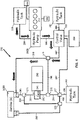
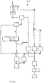
- FIG 2 there is shown a schematic diagram of a working machine including an engine according to the present invention.
- the engine includes an after treatment system 44 and an intake system 46, the principal operation of an engine with an intake system and exhaust after treatment system is known, but in summary air from the atmosphere passes through the intake system and into the engine.
- Fuel is injected either directly into the engine or into the intake system where it then passes with the air into the engine.
- the fuel air mixture is combusted to rotate a crank shaft or the like and exhaust products pass into the exhaust after treatment system.
- the exhaust after treatment system 44 will be arranged to prevent toxic exhaust products from entering the atmosphere.
- Examples of exhaust after treatment systems include a diesel oxidation catalyst, a selective catalytic reducer, a NO x absorber, a lean NO x trap, a three way catalyst or a diesel particulate filter.
- the working machine also includes a gearbox 48, and a kinetic energy storage device 50.
- the kinetic energy storage device is a flywheel and is therefore capable of storing energy in a kinetic form i.e. when the flywheel is rotating the rotating mass of the flywheel stores energy in a kinetic form (this can be contrasted with an electric cell of a battery which stores energy in a chemical form).
- a clutch 52 selectively operable to couple an engine output shaft (such as crank shaft) to an input of the step up gearbox 48.
- the gearbox 48 has an output which is capable of driving the flywheel. Operation of the working machine 2 is as follows.
- the machine 2 has been left, inoperative, over night and the operator wishes to use the machine. Because the machine has been left inoperative for several hours, it will be at an ambient temperature of the atmosphere, and in particular the exhaust after treatment system will be at an ambient temperature of the atmosphere. Furthermore, the flywheel 50 will be stationary.
- the clutch 52 can be disengaged and the flywheel 50 will remain spinning at a relatively high speed whilst the speed of the engine may then be allowed to fall.
- the control system 54 can selectively engage the clutch 52 thereby causing the flywheel to reduce in speed and transfer energy from the flywheel to the engine which, then, increases in speed.
- the kinetic energy in the flywheel can be transferred via the engine through the transmission 14 to the rear wheels 22B to assist in propelling the machine 2 over the ground.
- the energy stored in the flywheel 50 can be transferred by the engine to the hydraulic pump 42 so as to assist in operating a hydraulic service.
- the engine can transfer energy to the flywheel and the flywheel can transfer energy to the engine.
- the flywheel in addition to the flywheel being driven by the engine, the flywheel may also be driven by other sources of energy.
- the flywheel may transfer energy to alternative energy absorbers without that energy passing through the engine.
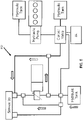
- FIG 3 there is shown a further embodiment of a working machine 102 with components that fulfil the same function as those components of working machine 2 being labelled 100 greater.
- a comparison between figures 2 and 3 shows that the only difference between working machine 2 and working machine 102 is that working machine 102 includes a further gearbox 149 and a further clutch 153 and associated mechanical drive parts 70, 71 and 72.
- energy can be transferred from the hydraulic pump 142 via clutch 153 and gearbox 149 to the kinetic energy storage device 150 in order to store energy in the kinetic energy storage device.
- Gearbox 148 is arranged such that the flywheel rotates faster than the engine when the clutch 152 is engaged. Gearbox 148 is therefore a step up gearbox when considering the transfer of energy from the engine to the flywheel. Gearbox 48 may be arranged to drive the flywheel at a speed which is at least 10 times faster than that of the engine speed.
- Gearbox 149 may be arranged to drive the hydraulic pump at a slower speed than the speed at which the flywheel 150 is spinning. In one embodiment gearbox 149 is a step down gearbox when considering the transfer of energy from flywheel 150 to the hydraulic pump 142.
- the clutch 152 and gearbox 148 of working machine 102 could be transposed, i.e. the engine 112 could drive the gearbox 148 which in turn would drive the clutch 152 which in turn would drive the flywheel 150.
- the clutch 153 and gearbox 149 of working machine 102 could be transposed, i.e. the flywheel 150 could drive the clutch 153 which would drive the gearbox 149 which would drive the hydraulic pump 142.
- clutch 52 and gearbox 48 of working machine 2 could be transposed.
- the kinetic energy storage device is a flywheel.
- the flywheel may run in an evacuated chamber or in a partially evacuated chamber so as to reduce friction and windage losses.
- the flywheel may rotate faster than 20,000 revolutions per minute (RPM).
- the flywheel may rotate faster than 40,000 RPM or alternatively faster than 60,000 RPM.
- One or more of gearboxes 48, 148 and 149 may be a continuously variable transmission (CVT) type of gearbox.
- the CVT gearbox may include a range change part in series with the CVT part in order to increase the working range of rotational speeds of a flywheel of the kinetic energy storage device.
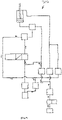
- the working machine 202 includes hydraulic tanks 280, 281 and 282, a control valve 283 and hydraulic lines 284, 285, 286, 287, 288, 289, 290, 291, 292, 293, 294, 295, 296, 297 and 298.
- Hydraulic couplings/valves 273, 274, 275, 276, 277, 278 and 279 connect the various components.
- a control system 254 is connected to the control valve and also has other connections (not shown) with other parts of the system in order to ensure the correct operation of the hydraulic system.
- the hydraulic pump 242B is a variable displacement pump.
- Gearbox 248 is arranged such that the kinetic energy storage device 250 rotates faster than pump 242B.
- the kinetic energy storage device 250 is arranged to recover energy from the service 203B (and any other services that it may be connected to) where that energy would otherwise be wasted.
- service 203B is the equivalent of actuator ram 3B which causes the front loading arm 23A to pivot relative to the chassis 21.
- the extension of ram 3B causes lifting of the front loading arm 23A and retraction of hydraulic ram 3B causes lowering of the loading arm 23A.
- lifting of the loading arm 23A requires energy input from the engine 12, whereas typically lowering of the loading arm 23A does not, since the loading arm will fall under the influence of gravity from a raised position to a lowered position.
- crowding of the bucket 24A requires energy input into service 3A, whereas dumping of the bucket typically does not, since the bucket will dump under the influence of gravity.
- the lifting of the back hoe arm 23B requires energy whereas lowering typically does not.
- Lifting of the dipper arm 31 requires energy whereas lowering of the dipper arm typically does not.
- Crowding of the bucket 24B typically requires energy, whereas dumping of the bucket 24B typically does not.
- Lowering of the stabilising legs 32 requires energy, but, for example, where the rear wheels have been lifted off the ground, raising of the stabilising legs 32 to the point where the weight of the machine is taken on the rear wheels does not.
- an actuator causes a rear portion 30A of carriage 32 to slew relative to the chassis 21. Since the back hoe arm, dipper arm and bucket are all attached to the rear portion 30A of the carriage, then these components also slew relative to the chassis. In order to start the slew motion, energy is required to overcome the inertia of the slewed components. However, in order to stop the slew motion in a controlled manner, in the prior art this is carried out by dissipating the kinetic energy as heat within the hydraulic system. The present invention allows recovery of the kinetic slew energy.
- Some working machines have a hydrostatic transmission to propel them along the ground and when it is necessary to slow the vehicle, the kinetic energy of the vehicle is dissipated as heat energy within the friction brakes.
- the present invention allows recovery of this kinetic energy.
- Figure 4 shows the situation when a service (in this case 203B) requires energy, in this case in order to lift the front loading arm.
- the control system 254 operates such that the engine 212 drives the hydraulic pump 242A such that hydraulic fluid passes from the hydraulic tank 280 through line 284 through the hydraulic pump 242A through line 285 through the control valve 283 through line 287 through line 288 to the service 203B thereby lifting the front loading arm.
- no energy is transferred from the kinetic energy storage device 250 to the service, since in this example the kinetic energy storage device is not storing any energy (for example where the kinetic energy storage device is a flywheel, the flywheel is stationary).
- the kinetic energy storage device 250 operates to drive the hydraulic pump 242B via the gear box 248.
- the control system 254 operates such that hydraulic fluid from the hydraulic tank 282 passes through line 296, through line 295, through line 290, through line 291, through hydraulic pump 242B, through line 292, through line 298, through line 288 to the hydraulic service 203B.
- the service has been operated solely by energy taken from the kinetic energy storage device 250.
- control system 254 operates such that the hydraulic fluid will pass from hydraulic pump 242B through line 292 and 298 into line 288 where it will be joined by a hydraulic fluid passing from hydraulic pump 242A through line 285 and 287 to line 288.
- Figure 6 shows the situation where energy can be transferred from the service 203B to the kinetic energy storage device 250.
- the control system 254 operates such that hydraulic fluid passes from the service 203B through line 298 through line 291 through pump 242B through line 292 through line 294 through line 296 to the hydraulic tank 282.
- the hydraulic pump will be acting as a hydraulic motor, i.e. the hydraulic fluid will drive the hydraulic pump 242B and cause it to rotate. This rotation is transferred through gearbox 248 to kinetic energy storage device 250.
- the potential energy lost by the loading arm will have been converted into kinetic energy stored in the kinetic energy storage device 250.
- the kinetic energy storage device only has a limited capacity for storing kinetic energy, typically where the kinetic energy storage device is a flywheel, that limit is defined by the maximum speed of rotation of the flywheel.
- the control system 254 operates such that hydraulic fluid from the service passes through line 288, through line 287, through control valve 283, through line 286 to the hydraulic tank 281. Because the operator will wish to lower the front loading arm in a controlled manner, the control valve ensures the correct controlled movement of the front loading arm.
- the potential energy lost by the front loading arm is all converted to heat energy within the hydraulic fluid (as per the prior art) since in this scenario, the kinetic energy storage device 250 has no capacity for any further energy.
- the engine 212 includes an intake system 246 and an exhaust after treatment system 244.
- the exhaust after treatment system 244 will be relatively cold and the kinetic energy storage device may not be storing any energy, for example where the kinetic energy storage device is a flywheel, a flywheel may be stationary.
- the kinetic energy storage device 250 can be used to load up the engine 212 so as to store energy in the kinetic energy storage device and increase the temperature of the exhaust after treatment system as follows.
- control system 254 operates such that hydraulic fluid passes from tank 280 through line 284 through the hydraulic pump 242A through line 285 through control valve 283, through line 287, through line 288, through line 289 (bypassing service 203B), through line 291, through hydraulic pump 242B, through line 292, through line 294, through line 296, to the hydraulic tank 282.
- pump 242B acts as a hydraulic motor which drives gear box 248 which in turn drives the kinetic energy storage device 250.
- the pump 242B and kinetic energy storage device 250 are at least operably coupled to the prime mover (engine 212) hydraulically, i.e. without the hydraulic parts of the system the pump 242B and kinetic energy storage device cannot be operably coupled to the engine.
- the coupling via clutch 152 and gearbox 148 is a mechanical coupling and the coupling via hydraulic pump 142, mechanical drive path 72, clutch 153, mechanical drive path 71, gearbox 149 and mechanical drive path 70 is also a mechanical coupling.
- Gearbox 248 may be a continuously variable transmission (CVT) type of gearbox.
- the CVT gearbox may include a range change part in series with the CVT part in order to increase the working range of rotational speeds of a flywheel of the kinetic energy storage device.
- Hydraulic tanks 280, 281, 282 are shown as separate tanks for ease of understanding. Typically there will be a single, common tank.
- the hydraulic machine comprises a first and second hydraulic machine.
- the hydraulic machine may be a single hydraulic machine such as a single pump/motor.
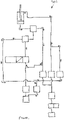
- Machine 302 including an engine 312 (also known as a prime mover) and an engine driven pump 314.
- Machine 302 includes hydraulic tanks 316 and 318.
- a hydraulic machine 320 in the form of a variable capacity hydraulic pump/motor (in one example a variable capacity swash plate pump/motor) is selectively coupleable to a kinetic energy storage device 322 in the form of a flywheel by a clutch 324 and gearbox 325.
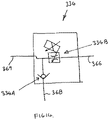
- a hydraulic service 303 is in the form of a hydraulic ram 326 having a main hydraulic chamber 328 and a rod side hydraulic chamber 330.
- a valve block 334 includes a variable valve 334B and a check valve 334A as best seen in figure 14 . There is also included valves 340, 342 and 344 and pump shut off valve 346. Hydraulic lines 350, 351, 352, 353, 354, 355, 356, 357, 358, 359, 360, 361, 362, 363, 364, 365, 366, 367, 368, 369 and 370 connect various components as will be further described below.
- a control system 348 (only shown on figure 8 ) controls the various valves as will be further described below. For clarity purposes, the connection between the control system 348 and the various valves has not been shown on figure 8 .
- any hydraulic pressure in any of the hydraulic lines will typically have decayed to zero, the flywheel 322 will be stationary and the engine 312 will be stationary.
- the control system Prior to starting the engine, the control system is operated to close valves 334B, 342 and 344.
- the control system opens valve 340.
- the control system operates diverter valve 332 so that hydraulic lines 367 and 363 are connected, and as such line 368 will be isolated from both lines 367 and 363.
- the control system opens valve 346 and valve 338.
- suction check valve 336 prevents pressurised fluid in line 362 passing to line 361. Because valve 342 is closed, then hydraulic line 357 is not pressurised. Because valve 334B is closed, then lines 368 and 369 are not pressurised by fluid from line 366.
- hydraulic fluid is supplied to the hydraulic machine 320 from the engine driven pump 314.
- the hydraulic machine 320 is arranged to operate as a motor and because the control system has engaged clutch 324 the rotation of the hydraulic machine 320 causes a consequential transfer of energy to the kinetic energy storage device 322 which therefore speeds up from its initial rest condition.
- the control system varies the capacity of the hydraulic machine 320.
- the flywheel speed of the kinetic energy storage device will be relatively low and the control system will set the displacement capacity of the hydraulic machine to be a relatively high (for example by setting the swash plate angle of a swash plate pump/motor at a relatively high angle).
- the flywheel will progressively increase in rotational speed and the control system will progressively reduce the displacement capacity of the hydraulic machine. In this way, the rotational speed of the hydraulic machine will progressively increase as the rotational speed of the flywheel increases.
- Figure 9 shows the fluid flow during system start-up and table 1 summarises the various positions of the valves.
- the speed of the flywheel will progressively increase and once it has reached a predetermined maximum idle speed then the clutch 324 is disengaged and the valve 346 is closed. Once this has occurred, the speed of the flywheel will progressively decrease, as a result of internal friction of the flywheel mechanism.
- the valve 346 is opened and the clutch 324 is re-engaged and the control system controls the displacement capacity of the hydraulic machine (as described above) such that the flywheel increases in speed until the predetermined maximum idle speed is achieved whereupon the valve 346 is again closed and the clutch 324 is again disengaged. In this manner the flywheel can be kept running at a speed between its maximum idle speed and its minimum idle speed until such time as the service 303 is operated.
- the pressurised hydraulic fluid in the main hydraulic chamber 328 is fed to the hydraulic machine 320 which then acts as a hydraulic motor so as to increase the speed of the flywheel 322.
- valve 334B is opened by the control system thereby coupling hydraulic line 369 to hydraulic line 366.
- Valve 340, valve 346 and valve 342 are all closed and valve 344 is open.
- pressurised hydraulic fluid from the main hydraulic chamber 328 passes into hydraulic line 369, through valve 334B into hydraulic line 366 into hydraulic line 365 into hydraulic line 364 and through the hydraulic machine 320 which acts as a motor.
- Clutch 324 is engaged and accordingly the motor transfers energy to the kinetic energy storage device 322 which in turn speeds up (to a speed faster than the maximum idle speed) to store the energy in a kinetic form.
- the control system varies the capacity of the hydraulic machine 320.
- the rotational speed of the kinetic energy storage device will be somewhere between the minimum idle speed and the maximum idle speed.
- the control system will set the capacity of the hydraulic machine to a suitable displacement (for example by setting the swash plate angle of the swash plate pump/motor to a suitable angle).
- a suitable displacement for example by setting the swash plate angle of the swash plate pump/motor to a suitable angle.
- the flywheel will progressively increase in rotational speed and the control system will progressively reduce the displacement capacity of the hydraulic machine (for example by reducing the swash plate angle of a swash plate pump/motor). In this way the rotational speed of the hydraulic machine will progressively increase as the rotational speed of the flywheel is increased.
- Figure 10 shows how the hydraulic fluid flows in the system when energy is being recovered from the hydraulic service 303.
- the amount of energy recoverable from the hydraulic circuit may exceed the amount of energy which can be supplied to the kinetic energy storage device.
- the maximum torque which can be applied to an input shaft of the kinetic energy storage device may be limited, for example if an excess torque is applied to the input shaft of the kinetic energy storage device then damage may occur. Accordingly, there may be certain circumstances where not all the power that is potentially recoverable from the service 303 can be transferred to the kinetic energy storage device 322.
- the hydraulic service 303 is a hydraulic ram which raises and lowers a back hoe arm such as back hoe arm 23B as shown in figure 1 , then there may be circumstances where the operator of working machine wishes to lower the arm faster than the energy of the lowering arm can be transferred to the kinetic energy storage device 322.
- valves 340 and 342 may be partially opened in order to divert hydraulic fluid from the main hydraulic chamber 328 away from the hydraulic machine 320.
- Figure 11 shows some of the hydraulic fluid from line 366 passing into line 370, through valve 340 into line 354, into line 353, through valve 342, into line 357 and then on through line 358 to the rod side hydraulic chamber 330.
- the remainder of the hydraulic fluid from the main hydraulic chamber 328 passes through hydraulic machine 320 (the capacity of which is controlled by the control system as described above) diverter valve 322 and valve 334 in a manner similar to that shown in figure 10 in order to recover energy from that hydraulic fluid.
- the hydraulic machine In order to re-use the recovered energy, the hydraulic machine is powered by the kinetic energy storage device and acts as a hydraulic pump to supply pressurised hydraulic fluid to the main hydraulic chamber 328 of the hydraulic service 303.
- valves 340, 342 and 346 are closed and valve 344 is open.
- Valve 334B is closed.
- Diverter valve 332 couples lines 367 to line 368 thereby isolating line 363 from both lines 367 and 368.
- the kinetic energy previously stored in the kinetic energy storage device 322 is transferred via clutch 324 and gearbox 325 to the hydraulic machine 320 which acts as a pump and draws hydraulic fluid from tank 318 via line 361 through check valve 336 and lines 362 and 364.
- the hydraulic fluid which has been pressurised by the hydraulic machine 320 acting as a pump then passes into line 367 through diverter valve 332 into line 368 through check valve 334A into line 369 and into the main hydraulic chamber 328, thereby operating the hydraulic service 303 to do work.
- the control system varies the capacity of the hydraulic machine.
- the flywheel speed of the kinetic energy storage device will be relatively high.
- the control system will set the displacement capacity of the hydraulic machine to a relatively low displacement (for example by setting the swash plate angle of a swash plate pump/motor at a relatively low angle).
- the flywheel of the kinetic energy storage device will progressively decrease in rotational speed and the control system will progressively increase the displacement capacity of the hydraulic machine. In this way the rotational speed of the hydraulic machine will progressively decrease as the rotational speed of the flywheel progressively decreases.
- Figure 12 shows the flow of hydraulic fluid under these circumstances.
- the total amount of energy required to operate the hydraulic service is more than the energy stored in the kinetic energy storage device.
- the operator may require a boom or the like to be fitted to its full height whereas the energy stored in the kinetic energy storage device is only sufficient to lift the boom or the like to half its full height.
- the energy required to lift the boom to half its full height will be supplied by the kinetic energy storage device and the energy required to lift the boom from half its full height to its full height will be supplied by the engine.
- the engine 312 will drive the engine driven pump 314 which will take hydraulic fluid from tank 316 via line 350 and supply pressurised hydraulic fluid through line 351 through open valve 346 through open valve 340 through line 370 and line 366 through open valve 344B thereby supplying hydraulic fluid to the main hydraulic chamber 328 so as to lift the boom in this example from half height to full height.
- the hydraulic machine 320 is a swash plate pump
- the swash plate may be set to a zero degree angle to prevent fluid passing through the hydraulic machine.
- a separate valve may be provided to prevent fluid passing through the hydraulic machine, for example a valve may be positioned in hydraulic line 365 or hydraulic line 364 for this purpose.
- Figure 13 shows the flow of hydraulic fluid under these circumstances.
- the return flow from the rod side hydraulic chamber 330 is via hydraulic line 358 and 356, open valve 344, hydraulic line 355 and 359, open anti-cavitation valve 338, line 360 to tank 318 in a manner similar to that shown in figure 12 .
- the amount of energy required to operate the hydraulic service may exceed the amount of energy which can be supplied by the kinetic energy storage device.
- the hydraulic service 303 is a hydraulic ram which raises and lowers the back hoe arm, such as back hoe arm 23B as shown in figure 1
- pressurised hydraulic fluid flow from the hydraulic machine 320 to the valve block 334, as shown in figure 12 is combined with pressurised hydraulic flow from the engine driven on pump 314 arriving at the valve block 334 as shown in figure 13 .
- the working machine 302 may be any type of working machine and in particular is not limited to a back hoe loader machine (an example of which is shown in figure 1 ).
- the hydraulic service 303 is not limited to being a hydraulic ram. The hydraulic service 303 could operate to "slew" one part of the working machine relative to another part of the working machine.
- the hydraulic ram could cause a bucket to pivot relative to a front loading arm, or could cause a front loading arm to pivot relative to a chassis, or could cause a back hoe arm to pivot about a generally horizontal axis relative to a carriage, or could cause a dipper arm to pivot relative to a back hoe arm, or could cause a bucket to pivot relative to a dipper arm, or could cause extension and/or retraction of stabilising legs relative to a chassis of the working machine, or could cause a carriage to move laterally relative to a chassis.
- the hydraulic service 303 is a hydraulic ram it is not limited to being operated as discussed above and a person skilled in the art would readily appreciate that other types of hydraulic services are known and are applicable to the hydraulic service 303.
- the engine 312 may be an internal combustion engine, and in particular a compression ignition internal combustion engine such as a diesel engine or a spark ignition internal combustion engine such as a petrol engine. However, other types of engines are applicable to the present invention.
- the engine driven pump 14 may be a fixed displacement pump or it may be a variable displacement pump.
- the engine driven pump 314 may be directly coupled to the engine, i.e. it may be driven at engine speed or alternatively it may be coupled to the engine via a gear arrangement, and therefore may or may not rotate at engine speed.
- tanks 316 and 318 have been shown as separate tanks, though typically they may be a single common tank.
- the kinetic energy storage device 322 in one example is a flywheel, in particular a solid flywheel (i.e. not a fluid flywheel).
- Device 322 is coupled to the hydraulic machine 320 via clutch 324 and gearbox 325.
- the kinetic energy storage device 322 may be coupled to clutch 324 which in turn is coupled to gearbox 325 which in turn is coupled to the hydraulic machine 320, or alternatively the kinetic energy storage device 322 may be coupled to the gearbox 325 which in turn is coupled to the clutch 324 which in turn is coupled to the hydraulic machine 320.
- the gearbox may be a planetary gearbox.
- the clutch may be selectively engaged to prevent movement of one part of the planetary gearbox moving relative to another part of the planetary gearbox and may be selectively disengaged to allow one part of the planetary gearbox to move relative to the other part of the planetary gearbox.
- the clutch may be engaged to prevent a ring gear of a planetary gearbox rotating relative to a casing of a planetary gearbox.
- the hydraulic machine may drive planets of a planetary gearbox which in turn drives a sun of a planetary gearbox which in turn drives the kinetic energy storage device.
- the kinetic energy storage device may drive a sun of a planetary gearbox which in turn may drive planets of a planetary gearbox which may in turn drive the hydraulic machine.
- the diverter valve 332 may be operated by a hydraulic pilot signal or it may be operated by a solenoid.
- the valve 334B as shown in figure 14 is a variable orifice solenoid actuated valve, though in further embodiments pilot pressure actuation of this valve is possible and an alternative variable type valve may be used.
- Valve 338 may be a solenoid operated valve and it may be a proportional valve.
- Valves 340, 342 and 344 may be solenoid operated variable valves.
- Working machine 302 may incorporate an exhaust after treatment system.
- the engine 312 may be started and the kinetic energy storage device 322 may apply a load to the engine so as to store energy in the kinetic energy storage device 322 and increase the temperature of the exhaust after treatment system.
Landscapes
- Engineering & Computer Science (AREA)
- General Engineering & Computer Science (AREA)
- Mechanical Engineering (AREA)
- Chemical & Material Sciences (AREA)
- Structural Engineering (AREA)
- Civil Engineering (AREA)
- Combustion & Propulsion (AREA)
- Mining & Mineral Resources (AREA)
- Transportation (AREA)
- Fluid Mechanics (AREA)
- Physics & Mathematics (AREA)
- Analytical Chemistry (AREA)
- Life Sciences & Earth Sciences (AREA)
- Geology (AREA)
- Fluid-Pressure Circuits (AREA)
- Operation Control Of Excavators (AREA)
- Arrangement Or Mounting Of Propulsion Units For Vehicles (AREA)
Claims (12)
- Système hydraulique incluant un fluide hydraulique, une machine hydraulique (242A, 242B) servant à pressuriser le fluide hydraulique, un circuit hydraulique pour délivrer le fluide hydraulique à un actionneur hydraulique (203B), la machine hydraulique étant configurée pour recevoir le fluide hydraulique de l'actionneur hydraulique, et un dispositif de stockage d'énergie cinétique (250) servant à stocker l'énergie sous une forme cinétique, le dispositif de stockage d'énergie cinétique étant fonctionnellement couplé à la machine hydraulique, le système hydraulique étant configuré de sorte que la machine hydraulique est apte à transférer l'énergie du fluide hydraulique reçu de l'actionneur hydraulique à un dispositif de stockage d'énergie cinétique, caractérisé en ce que la machine hydraulique est définie par une première pompe hydraulique (242A) servant à pressuriser le fluide hydraulique et une seconde pompe hydraulique configurée pour recevoir le fluide hydraulique de l'actionneur hydraulique, et le dispositif de stockage d'énergie cinétique est fonctionnellement couplé à la seconde pompe hydraulique, le système étant configuré de sorte que la seconde pompe hydraulique est apte à transférer l'énergie du fluide hydraulique pressurisé reçu de l'actionneur hydraulique au dispositif de stockage d'énergie cinétique, la première pompe hydraulique étant configurée pour être entraînée mécaniquement par un moteur principal (212), le dispositif de stockage d'énergie cinétique étant une roue volante (250), la roue volante étant fonctionnellement couplée à la seconde pompe hydraulique via un engrenage (248) agencé de sorte que la roue volante tourne plus vite que la seconde pompe hydraulique.
- Système hydraulique tel que défini à la revendication 1, le système étant configuré de sorte que la machine hydraulique est apte à transférer de l'énergie du dispositif de stockage d'énergie cinétique au fluide hydraulique.
- Système hydraulique tel que défini à la revendication 2, dans lequel la machine hydraulique et le circuit hydraulique sont configurés pour transférer l'énergie du dispositif de stockage d'énergie cinétique à l'actionneur hydraulique.
- Système hydraulique tel que défini dans la revendication 1 ou 2, dans lequel la machine hydraulique et le circuit hydraulique sont configurés pour transférer l'énergie du dispositif de stockage d'énergie cinétique à un autre actionneur hydraulique.
- Système hydraulique tel que défini dans une des revendications précédentes, dans lequel le dispositif de stockage d'énergie cinétique est fonctionnellement couplé à la seconde pompe hydraulique via un embrayage qui peut fonctionner sélectivement pour empêcher un transfert d'énergie de la seconde pompe hydraulique au dispositif de stockage d'énergie cinétique.
- Système hydraulique tel que défini dans la revendication 1, dans lequel le dispositif de stockage d'énergie cinétique est couplé fonctionnellement à la seconde pompe hydraulique par un embrayage qui peut fonctionner sélectivement pour empêcher un transfert d'énergie du dispositif de stockage d'énergie cinétique à la seconde pompe hydraulique.
- Véhicule (202) incluant un système hydraulique tel que défini dans une des revendications précédentes, dans lequel l'actionneur hydraulique est apte à lever un bras de levage.
- Procédé de mise en fonctionnement d'un véhicule (202) incluant un système hydraulique tel que défini dans une des revendications 1 à 6, le procédé incluant les étapes consistant à :a) agencer l'actionneur hydraulique (203B) de sorte à fournir du fluide hydraulique pressurisé,b) entraîner la machine hydraulique (242A, 242B) au moyen du fluide hydraulique pressurisé,c) transférer l'énergie de la machine hydraulique au dispositif de stockage d'énergie cinétique (250),d) stocker l'énergie cinétique dans le dispositif de stockage d'énergie cinétique pour une période de temps.
- Procédé tel que défini dans la revendication 8, dans lequel une dépressurisation séparée d'au moins une partie de fluide hydraulique pressurisé par l'actionneur est prévue à l'étape b et/ou l'étape c, et/ou l'étape d).
- Procédé tel que défini dans une la revendication 9, dans lequel une dépressurisation séparée d'au moins une partie du fluide hydraulique pressurisé fourni par l'actionneur est prévue à l'étape c), y compris une modulation de la dépressurisation séparée de l'au moins une partie de fluide hydraulique pressurisé.
- Procédé tel que défini dans une des revendications 8 à 10 incluant l'étape consistant à transférer ensuite l'énergie du dispositif de stockage d'énergie cinétique à la machine hydraulique pour que celle-ci pressurise le fluide hydraulique et à fournir du fluide hydraulique pressurisé à l'actionneur hydraulique pour que celui-ci puisse travailler.
- Procédé de mise en fonctionnement d'un véhicule incluant un système hydraulique tel que défini dans une des revendications 1 à 6 incluant le fonctionnement de l'actionneur de sorte à réduire l'énergie potentielle du véhicule ou d'une partie du véhicule et à stocker au moins une partie de l'énergie potentielle sous forme d'énergie cinétique dans le dispositif de stockage d'énergie cinétique.
Applications Claiming Priority (3)
| Application Number | Priority Date | Filing Date | Title |
|---|---|---|---|
| GB1122221.3A GB2497955B (en) | 2011-12-23 | 2011-12-23 | Increasing the temperature of an i.c engine exhaust gas treatment system using a kinetic energy storage device to load the engine |
| GB1122223.9A GB2497956C (en) | 2011-12-23 | 2011-12-23 | Energy recovery system |
| PCT/GB2012/053251 WO2013093511A1 (fr) | 2011-12-23 | 2012-12-21 | Système hydraulique comprenant un dispositif de stockage de l'énergie cinétique |
Publications (2)
| Publication Number | Publication Date |
|---|---|
| EP2795002A1 EP2795002A1 (fr) | 2014-10-29 |
| EP2795002B1 true EP2795002B1 (fr) | 2022-03-30 |
Family
ID=47522720
Family Applications (1)
| Application Number | Title | Priority Date | Filing Date |
|---|---|---|---|
| EP12813083.8A Active EP2795002B1 (fr) | 2011-12-23 | 2012-12-21 | Système hydraulique comprenant un dispositif de stockage de l'énergie cinétique |
Country Status (7)
| Country | Link |
|---|---|
| US (1) | US10557481B2 (fr) |
| EP (1) | EP2795002B1 (fr) |
| JP (1) | JP6456144B2 (fr) |
| KR (1) | KR102046673B1 (fr) |
| CN (1) | CN104302845A (fr) |
| RU (1) | RU2621408C2 (fr) |
| WO (1) | WO2013093511A1 (fr) |
Families Citing this family (9)
| Publication number | Priority date | Publication date | Assignee | Title |
|---|---|---|---|---|
| DE102012008192A1 (de) * | 2012-04-26 | 2013-10-31 | Deutz Aktiengesellschaft | Hydraulikhybrid |
| GB2521379A (en) | 2013-12-18 | 2015-06-24 | Jc Bamford Excavators Ltd | A materials handling vehicle |
| GB2558609A (en) * | 2017-01-10 | 2018-07-18 | Bamford Excavators Ltd | Energy recovery system |
| US10480159B2 (en) * | 2017-06-05 | 2019-11-19 | Caterpillar Inc. | Kinetic energy recovery system for a machine |
| RU2668093C1 (ru) * | 2017-10-17 | 2018-09-26 | Федеральное государственное бюджетное образовательное учреждение высшего образования "Воронежский государственный лесотехнический университет имени Г.Ф. Морозова" | Рекуперативный гидропривод лесовозного автомобиля |
| KR102089757B1 (ko) | 2018-06-14 | 2020-04-23 | 하윤기 | 건설 중장비용 기계적 에너지 절감장치 |
| WO2020164103A1 (fr) * | 2019-02-15 | 2020-08-20 | Guangxi Liugong Machinery Co., Ltd. | Machine de construction avec agencement de volant |
| AU2019464016A1 (en) | 2019-08-27 | 2022-03-03 | Sandvik Mining And Construction G.M.B.H. | Hydraulic system, mining machine and method of controlling hydraulic actuator |
| WO2023092214A1 (fr) * | 2021-11-23 | 2023-06-01 | Artificial Lift Production Internatiol Corp. | Système et procédé de pompage régénérateur |
Family Cites Families (39)
| Publication number | Priority date | Publication date | Assignee | Title |
|---|---|---|---|---|
| GB1199572A (en) | 1966-09-28 | 1970-07-22 | Richfield Ind Equipment Ltd | Momentum Power-Storing Apparatus and Hydraulic Power System. |
| DE2451021B2 (de) * | 1974-10-26 | 1980-04-24 | Maschinenfabrik Augsburg-Nuernberg Ag, 8000 Muenchen | Vorrichtung zum Einspeichern bzw. Ausspeichem von Bremsenergie in einen bzw. aus einem Schwungmassenspeicher |
| DE2515048C3 (de) * | 1975-04-07 | 1982-02-18 | M.A.N. Maschinenfabrik Augsburg-Nuernberg Ag, 8000 Muenchen | Antriebsanordnung mit Energiespeicher, insbesondere für Straßenfahrzeuge |
| US4233858A (en) * | 1976-12-27 | 1980-11-18 | The Garrett Corporation | Flywheel drive system having a split electromechanical transmission |
| JPS57203860A (en) * | 1981-06-10 | 1982-12-14 | Hitachi Constr Mach Co Ltd | Engine starting device |
| SU1016449A1 (ru) * | 1981-12-16 | 1983-05-07 | Сибирский Ордена Трудового Красного Знамени Автомобильно-Дорожный Институт Им.В.В.Куйбышева | Гидропривод стрелы землеройно-транспортной машины |
| JPS59221464A (ja) | 1983-05-28 | 1984-12-13 | Hino Motors Ltd | 内燃機関の暖機運転促進装置 |
| JPS60109654A (ja) * | 1983-11-18 | 1985-06-15 | Hitachi Constr Mach Co Ltd | 動力回収装置 |
| US4888949A (en) * | 1988-07-18 | 1989-12-26 | Rogers Roy K | Propulsion system for a small vehicle |
| US5890468A (en) * | 1994-01-25 | 1999-04-06 | Komatsu Ltd. | Differential driving supercharger and method for controlling the same |
| EP0975480B1 (fr) * | 1997-04-18 | 2004-02-18 | Transport Energy systems Pty. Ltd. | Systeme de propulsion hybride pour vehicules routiers |
| JP2000136806A (ja) * | 1998-11-04 | 2000-05-16 | Komatsu Ltd | 圧油のエネルギー回収装置および圧油のエネルギー回収・再生装置 |
| RU2158220C1 (ru) * | 1999-07-27 | 2000-10-27 | Федеральное государственное унитарное предприятие "Конструкторское бюро специального машиностроения" | Гидравлический привод стрелового самоходного крана |
| US6502393B1 (en) | 2000-09-08 | 2003-01-07 | Husco International, Inc. | Hydraulic system with cross function regeneration |
| JP3679749B2 (ja) * | 2001-10-19 | 2005-08-03 | サクサ株式会社 | 油圧装置 |
| JP2004028212A (ja) | 2002-06-26 | 2004-01-29 | Komatsu Ltd | 圧油エネルギー同時回収装置 |
| US7451685B2 (en) | 2005-03-14 | 2008-11-18 | Husco International, Inc. | Hydraulic control system with cross function regeneration |
| US20080210500A1 (en) * | 2005-05-11 | 2008-09-04 | Walker Frank H | Hydraulic Regenerative Braking System For a Vehicle |
| US7261086B2 (en) | 2005-10-21 | 2007-08-28 | Southwest Research Institute | Fast warm-up of diesel aftertreatment system during cold start |
| SE531309C2 (sv) * | 2006-01-16 | 2009-02-17 | Volvo Constr Equip Ab | Styrsystem för en arbetsmaskin och förfarande för styrning av en hydraulcylinder hos en arbetsmaskin |
| US7658065B2 (en) * | 2006-01-30 | 2010-02-09 | Caterpillar Inc. | Hydraulic system having in-sump energy recovery device |
| US7444809B2 (en) * | 2006-01-30 | 2008-11-04 | Caterpillar Inc. | Hydraulic regeneration system |
| JP2008138439A (ja) * | 2006-12-01 | 2008-06-19 | Shin Caterpillar Mitsubishi Ltd | エネルギー回生装置をそなえた油圧ショベル及びその運転方法 |
| US7980073B2 (en) | 2008-05-08 | 2011-07-19 | Caterpillar Inc. | Hybrid system for a powertrain and hydraulic system |
| GB2460237A (en) * | 2008-05-20 | 2009-11-25 | Torotrak Dev Ltd | Vehicle kinetic energy recovery system |
| DE102008050553A1 (de) * | 2008-10-06 | 2010-04-15 | Wacker Neuson Se | Arbeitsgerät mit Hybridantrieb |
| CN101382046B (zh) * | 2008-10-23 | 2011-04-13 | 烟台大学 | 变惯量飞轮储能式修井机 |
| US8186154B2 (en) * | 2008-10-31 | 2012-05-29 | Caterpillar Inc. | Rotary flow control valve with energy recovery |
| JP5591830B2 (ja) * | 2009-01-27 | 2014-09-17 | ディーティーアイ グループ ビー.ブイ. | フライホイールモジュール |
| JP2010208417A (ja) * | 2009-03-09 | 2010-09-24 | Equos Research Co Ltd | 無段変速機 |
| GB2469864A (en) * | 2009-05-01 | 2010-11-03 | Ford Global Tech Llc | Hybrid vehicle and control method |
| JP2011127534A (ja) * | 2009-12-18 | 2011-06-30 | Yanmar Co Ltd | ハイブリッド式エンジン装置 |
| JP2011127543A (ja) * | 2009-12-18 | 2011-06-30 | Yanmar Co Ltd | ガスエンジン制御装置 |
| GB2476676B (en) * | 2010-01-04 | 2011-12-07 | Flybrid Systems Llp | Clutched flywheel transmission |
| JP5447031B2 (ja) * | 2010-03-12 | 2014-03-19 | トヨタ自動車株式会社 | 車両のモータ駆動装置 |
| DE102010063335A1 (de) * | 2010-12-17 | 2012-06-21 | Robert Bosch Gmbh | Mechanischer Energiespeicher für ein Fahrzeug |
| JP5333511B2 (ja) * | 2011-05-02 | 2013-11-06 | コベルコ建機株式会社 | 旋回式作業機械 |
| JP5857004B2 (ja) * | 2013-07-24 | 2016-02-10 | 日立建機株式会社 | 建設機械のエネルギ回生システム |
| CN105697474B (zh) * | 2014-12-11 | 2020-10-16 | 罗伯特·博世有限公司 | 用于做功机械的液压的设备和用于液压的设备的方法 |
-
2012
- 2012-12-21 RU RU2014128986A patent/RU2621408C2/ru active
- 2012-12-21 CN CN201280070579.8A patent/CN104302845A/zh active Pending
- 2012-12-21 JP JP2014548205A patent/JP6456144B2/ja active Active
- 2012-12-21 KR KR1020147019857A patent/KR102046673B1/ko active IP Right Grant
- 2012-12-21 WO PCT/GB2012/053251 patent/WO2013093511A1/fr active Application Filing
- 2012-12-21 US US14/367,228 patent/US10557481B2/en active Active
- 2012-12-21 EP EP12813083.8A patent/EP2795002B1/fr active Active
Also Published As
| Publication number | Publication date |
|---|---|
| US20150027109A1 (en) | 2015-01-29 |
| JP2015507725A (ja) | 2015-03-12 |
| KR20140116109A (ko) | 2014-10-01 |
| RU2621408C2 (ru) | 2017-06-05 |
| KR102046673B1 (ko) | 2019-11-19 |
| EP2795002A1 (fr) | 2014-10-29 |
| JP6456144B2 (ja) | 2019-01-23 |
| CN104302845A (zh) | 2015-01-21 |
| RU2014128986A (ru) | 2016-02-10 |
| WO2013093511A1 (fr) | 2013-06-27 |
| US10557481B2 (en) | 2020-02-11 |
Similar Documents
| Publication | Publication Date | Title |
|---|---|---|
| EP2795002B1 (fr) | Système hydraulique comprenant un dispositif de stockage de l'énergie cinétique | |
| US9989042B2 (en) | Propel circuit and work circuit combinations for a work machine | |
| CN101370989B (zh) | 用于控制工程机械内的液压缸的方法 | |
| JP4727653B2 (ja) | バッテリ式産業車両の荷役回生方法及び荷役回生システム | |
| US7634911B2 (en) | Energy recovery system | |
| US9803338B2 (en) | System and method for recovering energy and leveling hydraulic system loads | |
| EP2735657A1 (fr) | Chaîne cinématique d'un véhicule, notamment d'une machine de travail mobile | |
| EP2557239A1 (fr) | Circuit hydraulique combiné en boucle fermée et système de stockage d'énergie hydraulique | |
| US20150368879A1 (en) | Combined Hydraulic Implement and Propulsion Circuit with Hybrid Energy Capture and Reuse | |
| GB2497956A (en) | Hydraulic system with kinetic energy recovery and storage device | |
| US7356397B2 (en) | Crowd control system for a loader | |
| US20150063968A1 (en) | Flywheel excavator | |
| EP3181954A2 (fr) | Système hydraulique pour convertisseur de couple | |
| US20140314587A1 (en) | Check Valve Device In The Suction Side of A Hydrostatic Power-Unit That Can Be Operated In The Same Direction of Rotation As A Pump And As A Motor | |
| EP3784841B1 (fr) | Système hydraulique hybride destiné à un engin de chantier et procédé de commande du système hydraulique hybride | |
| EP2559880A2 (fr) | Système de moteur et véhicule | |
| JP2003314510A (ja) | 油圧エネルギー回生システム | |
| GB2558610A (en) | Energy recovery system | |
| GB2497955A (en) | Increasing the temperature of an i.c engine exhaust gas treatment system using a kinetic energy storage device to load the engine | |
| GB2558609A (en) | Energy recovery system |
Legal Events
| Date | Code | Title | Description |
|---|---|---|---|
| PUAI | Public reference made under article 153(3) epc to a published international application that has entered the european phase |
Free format text: ORIGINAL CODE: 0009012 |
|
| 17P | Request for examination filed |
Effective date: 20140716 |
|
| AK | Designated contracting states |
Kind code of ref document: A1 Designated state(s): AL AT BE BG CH CY CZ DE DK EE ES FI FR GB GR HR HU IE IS IT LI LT LU LV MC MK MT NL NO PL PT RO RS SE SI SK SM TR |
|
| RAP1 | Party data changed (applicant data changed or rights of an application transferred) |
Owner name: JC BAMFORD EXCAVATORS LTD |
|
| DAX | Request for extension of the european patent (deleted) | ||
| STAA | Information on the status of an ep patent application or granted ep patent |
Free format text: STATUS: EXAMINATION IS IN PROGRESS |
|
| 17Q | First examination report despatched |
Effective date: 20180727 |
|
| STAA | Information on the status of an ep patent application or granted ep patent |
Free format text: STATUS: EXAMINATION IS IN PROGRESS |
|
| RAP3 | Party data changed (applicant data changed or rights of an application transferred) |
Owner name: J.C. BAMFORD EXCAVATORS LIMITED |
|
| GRAP | Despatch of communication of intention to grant a patent |
Free format text: ORIGINAL CODE: EPIDOSNIGR1 |
|
| STAA | Information on the status of an ep patent application or granted ep patent |
Free format text: STATUS: GRANT OF PATENT IS INTENDED |
|
| RIC1 | Information provided on ipc code assigned before grant |
Ipc: F02D 41/02 20060101ALI20211019BHEP Ipc: B60K 6/10 20060101ALI20211019BHEP Ipc: F15B 21/14 20060101ALI20211019BHEP Ipc: F01N 9/00 20060101ALI20211019BHEP Ipc: E02F 9/22 20060101ALI20211019BHEP Ipc: B66F 9/20 20060101ALI20211019BHEP Ipc: B60W 10/30 20060101ALI20211019BHEP Ipc: B60W 10/24 20060101ALI20211019BHEP Ipc: E02F 9/20 20060101AFI20211019BHEP |
|
| INTG | Intention to grant announced |
Effective date: 20211117 |
|
| GRAS | Grant fee paid |
Free format text: ORIGINAL CODE: EPIDOSNIGR3 |
|
| GRAA | (expected) grant |
Free format text: ORIGINAL CODE: 0009210 |
|
| STAA | Information on the status of an ep patent application or granted ep patent |
Free format text: STATUS: THE PATENT HAS BEEN GRANTED |
|
| AK | Designated contracting states |
Kind code of ref document: B1 Designated state(s): AL AT BE BG CH CY CZ DE DK EE ES FI FR GB GR HR HU IE IS IT LI LT LU LV MC MK MT NL NO PL PT RO RS SE SI SK SM TR |
|
| REG | Reference to a national code |
Ref country code: GB Ref legal event code: FG4D |
|
| REG | Reference to a national code |
Ref country code: CH Ref legal event code: EP |
|
| REG | Reference to a national code |
Ref country code: DE Ref legal event code: R096 Ref document number: 602012077943 Country of ref document: DE |
|
| REG | Reference to a national code |
Ref country code: AT Ref legal event code: REF Ref document number: 1479301 Country of ref document: AT Kind code of ref document: T Effective date: 20220415 |
|
| REG | Reference to a national code |
Ref country code: IE Ref legal event code: FG4D |
|
| REG | Reference to a national code |
Ref country code: LT Ref legal event code: MG9D |
|
| PG25 | Lapsed in a contracting state [announced via postgrant information from national office to epo] |
Ref country code: SE Free format text: LAPSE BECAUSE OF FAILURE TO SUBMIT A TRANSLATION OF THE DESCRIPTION OR TO PAY THE FEE WITHIN THE PRESCRIBED TIME-LIMIT Effective date: 20220330 Ref country code: RS Free format text: LAPSE BECAUSE OF FAILURE TO SUBMIT A TRANSLATION OF THE DESCRIPTION OR TO PAY THE FEE WITHIN THE PRESCRIBED TIME-LIMIT Effective date: 20220330 Ref country code: NO Free format text: LAPSE BECAUSE OF FAILURE TO SUBMIT A TRANSLATION OF THE DESCRIPTION OR TO PAY THE FEE WITHIN THE PRESCRIBED TIME-LIMIT Effective date: 20220630 Ref country code: LT Free format text: LAPSE BECAUSE OF FAILURE TO SUBMIT A TRANSLATION OF THE DESCRIPTION OR TO PAY THE FEE WITHIN THE PRESCRIBED TIME-LIMIT Effective date: 20220330 Ref country code: HR Free format text: LAPSE BECAUSE OF FAILURE TO SUBMIT A TRANSLATION OF THE DESCRIPTION OR TO PAY THE FEE WITHIN THE PRESCRIBED TIME-LIMIT Effective date: 20220330 Ref country code: BG Free format text: LAPSE BECAUSE OF FAILURE TO SUBMIT A TRANSLATION OF THE DESCRIPTION OR TO PAY THE FEE WITHIN THE PRESCRIBED TIME-LIMIT Effective date: 20220630 |
|
| REG | Reference to a national code |
Ref country code: NL Ref legal event code: MP Effective date: 20220330 |
|
| REG | Reference to a national code |
Ref country code: AT Ref legal event code: MK05 Ref document number: 1479301 Country of ref document: AT Kind code of ref document: T Effective date: 20220330 |
|
| PG25 | Lapsed in a contracting state [announced via postgrant information from national office to epo] |
Ref country code: LV Free format text: LAPSE BECAUSE OF FAILURE TO SUBMIT A TRANSLATION OF THE DESCRIPTION OR TO PAY THE FEE WITHIN THE PRESCRIBED TIME-LIMIT Effective date: 20220330 Ref country code: GR Free format text: LAPSE BECAUSE OF FAILURE TO SUBMIT A TRANSLATION OF THE DESCRIPTION OR TO PAY THE FEE WITHIN THE PRESCRIBED TIME-LIMIT Effective date: 20220701 Ref country code: FI Free format text: LAPSE BECAUSE OF FAILURE TO SUBMIT A TRANSLATION OF THE DESCRIPTION OR TO PAY THE FEE WITHIN THE PRESCRIBED TIME-LIMIT Effective date: 20220330 |
|
| PG25 | Lapsed in a contracting state [announced via postgrant information from national office to epo] |
Ref country code: NL Free format text: LAPSE BECAUSE OF FAILURE TO SUBMIT A TRANSLATION OF THE DESCRIPTION OR TO PAY THE FEE WITHIN THE PRESCRIBED TIME-LIMIT Effective date: 20220330 |
|
| PG25 | Lapsed in a contracting state [announced via postgrant information from national office to epo] |
Ref country code: SM Free format text: LAPSE BECAUSE OF FAILURE TO SUBMIT A TRANSLATION OF THE DESCRIPTION OR TO PAY THE FEE WITHIN THE PRESCRIBED TIME-LIMIT Effective date: 20220330 Ref country code: RO Free format text: LAPSE BECAUSE OF FAILURE TO SUBMIT A TRANSLATION OF THE DESCRIPTION OR TO PAY THE FEE WITHIN THE PRESCRIBED TIME-LIMIT Effective date: 20220330 Ref country code: PT Free format text: LAPSE BECAUSE OF FAILURE TO SUBMIT A TRANSLATION OF THE DESCRIPTION OR TO PAY THE FEE WITHIN THE PRESCRIBED TIME-LIMIT Effective date: 20220801 Ref country code: ES Free format text: LAPSE BECAUSE OF FAILURE TO SUBMIT A TRANSLATION OF THE DESCRIPTION OR TO PAY THE FEE WITHIN THE PRESCRIBED TIME-LIMIT Effective date: 20220330 Ref country code: EE Free format text: LAPSE BECAUSE OF FAILURE TO SUBMIT A TRANSLATION OF THE DESCRIPTION OR TO PAY THE FEE WITHIN THE PRESCRIBED TIME-LIMIT Effective date: 20220330 Ref country code: CZ Free format text: LAPSE BECAUSE OF FAILURE TO SUBMIT A TRANSLATION OF THE DESCRIPTION OR TO PAY THE FEE WITHIN THE PRESCRIBED TIME-LIMIT Effective date: 20220330 Ref country code: AT Free format text: LAPSE BECAUSE OF FAILURE TO SUBMIT A TRANSLATION OF THE DESCRIPTION OR TO PAY THE FEE WITHIN THE PRESCRIBED TIME-LIMIT Effective date: 20220330 |
|
| PG25 | Lapsed in a contracting state [announced via postgrant information from national office to epo] |
Ref country code: PL Free format text: LAPSE BECAUSE OF FAILURE TO SUBMIT A TRANSLATION OF THE DESCRIPTION OR TO PAY THE FEE WITHIN THE PRESCRIBED TIME-LIMIT Effective date: 20220330 Ref country code: IS Free format text: LAPSE BECAUSE OF FAILURE TO SUBMIT A TRANSLATION OF THE DESCRIPTION OR TO PAY THE FEE WITHIN THE PRESCRIBED TIME-LIMIT Effective date: 20220730 Ref country code: AL Free format text: LAPSE BECAUSE OF FAILURE TO SUBMIT A TRANSLATION OF THE DESCRIPTION OR TO PAY THE FEE WITHIN THE PRESCRIBED TIME-LIMIT Effective date: 20220330 |
|
| REG | Reference to a national code |
Ref country code: DE Ref legal event code: R097 Ref document number: 602012077943 Country of ref document: DE |
|
| PG25 | Lapsed in a contracting state [announced via postgrant information from national office to epo] |
Ref country code: DK Free format text: LAPSE BECAUSE OF FAILURE TO SUBMIT A TRANSLATION OF THE DESCRIPTION OR TO PAY THE FEE WITHIN THE PRESCRIBED TIME-LIMIT Effective date: 20220330 |
|
| PLBE | No opposition filed within time limit |
Free format text: ORIGINAL CODE: 0009261 |
|
| STAA | Information on the status of an ep patent application or granted ep patent |
Free format text: STATUS: NO OPPOSITION FILED WITHIN TIME LIMIT |
|
| 26N | No opposition filed |
Effective date: 20230103 |
|
| PG25 | Lapsed in a contracting state [announced via postgrant information from national office to epo] |
Ref country code: SI Free format text: LAPSE BECAUSE OF FAILURE TO SUBMIT A TRANSLATION OF THE DESCRIPTION OR TO PAY THE FEE WITHIN THE PRESCRIBED TIME-LIMIT Effective date: 20220330 |
|
| P01 | Opt-out of the competence of the unified patent court (upc) registered |
Effective date: 20230524 |
|
| REG | Reference to a national code |
Ref country code: CH Ref legal event code: PL |
|
| REG | Reference to a national code |
Ref country code: BE Ref legal event code: MM Effective date: 20221231 |
|
| PG25 | Lapsed in a contracting state [announced via postgrant information from national office to epo] |
Ref country code: LU Free format text: LAPSE BECAUSE OF NON-PAYMENT OF DUE FEES Effective date: 20221221 |
|
| PG25 | Lapsed in a contracting state [announced via postgrant information from national office to epo] |
Ref country code: LI Free format text: LAPSE BECAUSE OF NON-PAYMENT OF DUE FEES Effective date: 20221231 Ref country code: IE Free format text: LAPSE BECAUSE OF NON-PAYMENT OF DUE FEES Effective date: 20221221 Ref country code: CH Free format text: LAPSE BECAUSE OF NON-PAYMENT OF DUE FEES Effective date: 20221231 |
|
| PG25 | Lapsed in a contracting state [announced via postgrant information from national office to epo] |
Ref country code: BE Free format text: LAPSE BECAUSE OF NON-PAYMENT OF DUE FEES Effective date: 20221231 |
|
| PGFP | Annual fee paid to national office [announced via postgrant information from national office to epo] |
Ref country code: GB Payment date: 20231214 Year of fee payment: 12 |
|
| PGFP | Annual fee paid to national office [announced via postgrant information from national office to epo] |
Ref country code: IT Payment date: 20231221 Year of fee payment: 12 Ref country code: FR Payment date: 20231221 Year of fee payment: 12 Ref country code: DE Payment date: 20231220 Year of fee payment: 12 |
|
| PG25 | Lapsed in a contracting state [announced via postgrant information from national office to epo] |
Ref country code: HU Free format text: LAPSE BECAUSE OF FAILURE TO SUBMIT A TRANSLATION OF THE DESCRIPTION OR TO PAY THE FEE WITHIN THE PRESCRIBED TIME-LIMIT; INVALID AB INITIO Effective date: 20121221 |
|
| PG25 | Lapsed in a contracting state [announced via postgrant information from national office to epo] |
Ref country code: CY Free format text: LAPSE BECAUSE OF FAILURE TO SUBMIT A TRANSLATION OF THE DESCRIPTION OR TO PAY THE FEE WITHIN THE PRESCRIBED TIME-LIMIT Effective date: 20220330 |