EP2794235B1 - Verfahren zur steuerung eines temperaturgradienten über die wanddicke eines behälters - Google Patents
Verfahren zur steuerung eines temperaturgradienten über die wanddicke eines behälters Download PDFInfo
- Publication number
- EP2794235B1 EP2794235B1 EP12859958.6A EP12859958A EP2794235B1 EP 2794235 B1 EP2794235 B1 EP 2794235B1 EP 12859958 A EP12859958 A EP 12859958A EP 2794235 B1 EP2794235 B1 EP 2794235B1
- Authority
- EP
- European Patent Office
- Prior art keywords
- temperature
- preform
- interior
- incompressible fluid
- exterior
- Prior art date
- Legal status (The legal status is an assumption and is not a legal conclusion. Google has not performed a legal analysis and makes no representation as to the accuracy of the status listed.)
- Active
Links
- 238000000034 method Methods 0.000 title claims description 38
- 239000012530 fluid Substances 0.000 claims description 111
- 239000000463 material Substances 0.000 claims description 28
- 229920000139 polyethylene terephthalate Polymers 0.000 claims description 22
- 239000005020 polyethylene terephthalate Substances 0.000 claims description 22
- 238000010438 heat treatment Methods 0.000 claims description 20
- 230000009477 glass transition Effects 0.000 claims description 15
- 239000007788 liquid Substances 0.000 claims description 12
- 238000001746 injection moulding Methods 0.000 claims description 8
- -1 polyethylene terephthalate Polymers 0.000 claims description 6
- 238000001816 cooling Methods 0.000 claims description 4
- 239000011248 coating agent Substances 0.000 claims description 3
- 238000000576 coating method Methods 0.000 claims description 3
- 239000000126 substance Substances 0.000 claims 1
- 230000032798 delamination Effects 0.000 description 16
- 230000015572 biosynthetic process Effects 0.000 description 6
- 239000007924 injection Substances 0.000 description 2
- 238000002347 injection Methods 0.000 description 2
- XLYOFNOQVPJJNP-UHFFFAOYSA-N water Substances O XLYOFNOQVPJJNP-UHFFFAOYSA-N 0.000 description 2
- 238000000071 blow moulding Methods 0.000 description 1
- 235000014171 carbonated beverage Nutrition 0.000 description 1
- 239000002178 crystalline material Substances 0.000 description 1
- 230000001419 dependent effect Effects 0.000 description 1
- 238000005516 engineering process Methods 0.000 description 1
- 230000007613 environmental effect Effects 0.000 description 1
- 239000000945 filler Substances 0.000 description 1
- 235000011389 fruit/vegetable juice Nutrition 0.000 description 1
- 239000011521 glass Substances 0.000 description 1
- 239000002991 molded plastic Substances 0.000 description 1
- 238000004806 packaging method and process Methods 0.000 description 1
- 239000004033 plastic Substances 0.000 description 1
- 229920003023 plastic Polymers 0.000 description 1
- 229920000728 polyester Polymers 0.000 description 1
- 229920000642 polymer Polymers 0.000 description 1
- 239000002861 polymer material Substances 0.000 description 1
- 239000012899 standard injection Substances 0.000 description 1
- 230000003746 surface roughness Effects 0.000 description 1
- 238000009423 ventilation Methods 0.000 description 1
Images

Classifications
-
- B—PERFORMING OPERATIONS; TRANSPORTING
- B29—WORKING OF PLASTICS; WORKING OF SUBSTANCES IN A PLASTIC STATE IN GENERAL
- B29D—PRODUCING PARTICULAR ARTICLES FROM PLASTICS OR FROM SUBSTANCES IN A PLASTIC STATE
- B29D22/00—Producing hollow articles
- B29D22/003—Containers for packaging, storing or transporting, e.g. bottles, jars, cans, barrels, tanks
-
- B—PERFORMING OPERATIONS; TRANSPORTING
- B29—WORKING OF PLASTICS; WORKING OF SUBSTANCES IN A PLASTIC STATE IN GENERAL
- B29C—SHAPING OR JOINING OF PLASTICS; SHAPING OF MATERIAL IN A PLASTIC STATE, NOT OTHERWISE PROVIDED FOR; AFTER-TREATMENT OF THE SHAPED PRODUCTS, e.g. REPAIRING
- B29C49/00—Blow-moulding, i.e. blowing a preform or parison to a desired shape within a mould; Apparatus therefor
- B29C49/42—Component parts, details or accessories; Auxiliary operations
- B29C49/46—Component parts, details or accessories; Auxiliary operations characterised by using particular environment or blow fluids other than air
-
- B—PERFORMING OPERATIONS; TRANSPORTING
- B29—WORKING OF PLASTICS; WORKING OF SUBSTANCES IN A PLASTIC STATE IN GENERAL
- B29C—SHAPING OR JOINING OF PLASTICS; SHAPING OF MATERIAL IN A PLASTIC STATE, NOT OTHERWISE PROVIDED FOR; AFTER-TREATMENT OF THE SHAPED PRODUCTS, e.g. REPAIRING
- B29C49/00—Blow-moulding, i.e. blowing a preform or parison to a desired shape within a mould; Apparatus therefor
- B29C49/42—Component parts, details or accessories; Auxiliary operations
- B29C49/78—Measuring, controlling or regulating
- B29C49/786—Temperature
-
- B—PERFORMING OPERATIONS; TRANSPORTING
- B29—WORKING OF PLASTICS; WORKING OF SUBSTANCES IN A PLASTIC STATE IN GENERAL
- B29C—SHAPING OR JOINING OF PLASTICS; SHAPING OF MATERIAL IN A PLASTIC STATE, NOT OTHERWISE PROVIDED FOR; AFTER-TREATMENT OF THE SHAPED PRODUCTS, e.g. REPAIRING
- B29C49/00—Blow-moulding, i.e. blowing a preform or parison to a desired shape within a mould; Apparatus therefor
- B29C49/42—Component parts, details or accessories; Auxiliary operations
- B29C49/46—Component parts, details or accessories; Auxiliary operations characterised by using particular environment or blow fluids other than air
- B29C2049/4602—Blowing fluids
- B29C2049/465—Blowing fluids being incompressible
- B29C2049/4664—Blowing fluids being incompressible staying in the final article
-
- B—PERFORMING OPERATIONS; TRANSPORTING
- B29—WORKING OF PLASTICS; WORKING OF SUBSTANCES IN A PLASTIC STATE IN GENERAL
- B29C—SHAPING OR JOINING OF PLASTICS; SHAPING OF MATERIAL IN A PLASTIC STATE, NOT OTHERWISE PROVIDED FOR; AFTER-TREATMENT OF THE SHAPED PRODUCTS, e.g. REPAIRING
- B29C2949/00—Indexing scheme relating to blow-moulding
- B29C2949/07—Preforms or parisons characterised by their configuration
- B29C2949/0715—Preforms or parisons characterised by their configuration the preform having one end closed
-
- B—PERFORMING OPERATIONS; TRANSPORTING
- B29—WORKING OF PLASTICS; WORKING OF SUBSTANCES IN A PLASTIC STATE IN GENERAL
- B29C—SHAPING OR JOINING OF PLASTICS; SHAPING OF MATERIAL IN A PLASTIC STATE, NOT OTHERWISE PROVIDED FOR; AFTER-TREATMENT OF THE SHAPED PRODUCTS, e.g. REPAIRING
- B29C49/00—Blow-moulding, i.e. blowing a preform or parison to a desired shape within a mould; Apparatus therefor
- B29C49/02—Combined blow-moulding and manufacture of the preform or the parison
- B29C49/06—Injection blow-moulding
-
- B—PERFORMING OPERATIONS; TRANSPORTING
- B29—WORKING OF PLASTICS; WORKING OF SUBSTANCES IN A PLASTIC STATE IN GENERAL
- B29C—SHAPING OR JOINING OF PLASTICS; SHAPING OF MATERIAL IN A PLASTIC STATE, NOT OTHERWISE PROVIDED FOR; AFTER-TREATMENT OF THE SHAPED PRODUCTS, e.g. REPAIRING
- B29C49/00—Blow-moulding, i.e. blowing a preform or parison to a desired shape within a mould; Apparatus therefor
- B29C49/42—Component parts, details or accessories; Auxiliary operations
- B29C49/64—Heating or cooling preforms, parisons or blown articles
- B29C49/6409—Thermal conditioning of preforms
- B29C49/6436—Thermal conditioning of preforms characterised by temperature differential
- B29C49/6454—Thermal conditioning of preforms characterised by temperature differential through the preform thickness
Definitions
- the present disclosure relates to a method for controlling the temperature gradient through the wall thickness of a container.
- PET polyethylene terephthalate
- % Crystallinity ⁇ ⁇ ⁇ a ⁇ c ⁇ ⁇ a ⁇ 100
- ⁇ is the density of the PET material
- pa is the density of pure amorphous PET material (1.333 g/cc)
- pc is the density of pure crystalline material (1.455 g/cc).
- EP-0 089 201 discloses heating a preform such that the interior temperature of the wall of the preform is greater than the exterior temperature of the wall of the preform.
- US-7491 358 discloses heating a preform such that a temperature profile is imparted between the interior and the exterior of the preform.
- US 2011/031659 discloses a method of forming a container from a polymeric matrial comprising a step of injecting a liquid into a heated preform to expand the preform into a container. The liquid is heated to a temperature substantially equal to the temperature of the preform.
- a method of forming a container according to claim 1 includes providing a preform of the container.
- the preform has a wall with an interior region and an exterior region.
- the method also includes disposing the preform in a mold cavity wherein the mold cavity has a mold surface.
- the method includes introducing an incompressible fluid into the preform to expand the preform toward the mold surface.
- the interior region of the wall has a first interior temperature prior to the introduction of the incompressible fluid and a second interior temperature after the introduction of the incompressible fluid.
- the exterior region of the wall has a first exterior temperature prior to the introduction of the incompressible fluid and a second exterior temperature after the introduction of the incompressible fluid.
- the method further includes controlling the first interior temperature to be greater than the first exterior temperature prior to the introduction of the incompressible fluid.
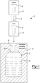
- the container 12 can be formed from a preform 14 (i.e., a parison) in some embodiments.
- a preform 14 i.e., a parison
- the container 12 can be a bottle, a jar, or any other suitable type of container, and the container 12 can be made from any suitable polymeric material, such as polyethylene terephthalate (PET). Also, the preform 14 and the container 12 can have any suitable shape, dimensions, and internal volume without departing from the scope of the present disclosure. Furthermore, although FIG. 1 illustrates the apparatus 10 as forming only one container 12 from a single preform 14, it will be appreciated that the apparatus 10 can be used for forming any number of containers 12 from respective preforms 14.
- PET polyethylene terephthalate
- the preform 14 can be provided in a gaylord 16 or other suitable handling container.
- the preform 14 can be injection molded in a standard injection molding machine and then stored and/or transported within the gaylord 16.
- the preform 14 can be fed into and positioned within an oven 18 via an infeed device 20.
- the oven 18 can heat the preform 14, as will be discussed before the preform 14 is blow molded.
- the infeed device 20 can be a conveyor, a movable spindle, or another type.
- the preform 14 can be automatically or manually disposed within a blow mold 22.
- the blow mold 22 can include an interior mold surface 24 therein.
- a fluid 26 can be introduced into the preform 14.
- the flow of fluid 26 can cause the preform 14 to expand toward the mold surface 24 to form the container 12.
- the fluid 26 is a liquid commodity (e.g., water, carbonated beverage, incompressible fluid, etc.) that is ultimately sealed, stored, shipped, and marketed inside the container 12.
- the container 12 can be formed from the preform 14 and filled with the fluid 26 in a substantially simultaneous fashion.
- the fluid 26 is air or another gas that forms the container 12 but that escapes from the container 12 before the container 12 is subsequently filled and sealed.
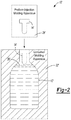
- the apparatus 10' can include an injection molding apparatus 28' that is used to form the preform 14' via injection molding. Then, the preform 14' can be disposed within the blow mold 22'. Next, the fluid 26' can be introduced into the preform 14' to form the container 12' as explained above.
- FIGS. 1 and 2 can share many of the same features, and the containers 12, 12' can be formed and filled in similar ways.
- the following discussion will primarily refer back to the embodiments of FIG. 1 except as specifically noted below. However, it will be appreciated that the following discussion can apply to both the embodiments of FIG. 1 and FIG. 2 .
- the preform 14 (and, thus, the container 12) can include a wall 30 with an exterior region 32 and an interior region 34.
- the interior region 34 can define the interior volume of the preform 14 and container 12.
- the exterior region 32 can be opposite the interior region 34.
- the interior region 34 can have an interior temperature, and the exterior region 32 can have an exterior temperature.
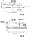
- the apparatus 10 can be used to control the interior temperature to be within a predetermined range of the exterior temperature. This can reduce the likelihood of the interior region 34 delaminating from the exterior region 32. More specifically, as shown in the top graph of FIG. 3A representing the prior art, once a preform exits the oven and is ready to be filled to form the container, the interior and exterior temperatures can be substantially equal. However, during filling, the interior temperature can decrease at a significantly faster rate than the exterior temperature. This can cause a delamination 36 to form as shown in FIG. 3C .
- wall 30 can comprise a monolithic structure or can comprise a multi-layer structure. It should be understood that although the present disclosure employs the terms exterior region 32 and interior region 34 in connection with wall 30, each of these regions can represent merely a general portion or section of a monolithic wall structure or each of these regions can represent separate distinct layers in a multi-layer wall structure. Therefore, it is important to recognize that the discussion, drawings, and claims of the present application are not to be limited to any particular wall structure unless otherwise noted and thus the use of the term region in the specification or a demarcation line in the drawings are used in a positionally-relative context rather than a distinct-layer context.
- the present teachings can be employed for controlling the interior temperature such that delaminations 36 are unlikely to form.
- the interior temperature of the preform 14 can be significantly greater than the exterior temperature. Then, once the container 12 is formed and filled with the liquid, the interior temperature will not fall significantly below the outer temperature which may result in variation of stretching characteristics. As such, the interior region 34 is less likely to delaminate from the exterior region 32.
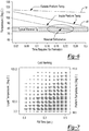
- FIGS. 4, 5 , and 6 illustrate the change in exterior temperature (represented by line 38) and the change in interior temperature (represented by line 40) while the container 12 is formed and filled with the fluid 26.
- the interior temperature can be initially greater than the exterior temperature, but the interior temperature can rapidly reduce, and by the time filling is completed, the interior temperature can be less than the exterior temperature.
- the interior temperature is below the exterior temperature initially and gradually reduces during filling.
- the change in temperature gradient between the interior and exterior temperatures during filling can be controlled.
- a predetermined amount of the fluid 26 can be introduced into the container 12 before the internal temperature drops below the exterior temperature (i.e., point 50 in FIGS. 4 and 5 ).
- at least approximately 10% of the final amount of the fluid 26 can be introduced before the internal temperature drops below the exterior temperature.
- at least approximately 25% of the final amount of the fluid 26 can be introduced before the internal temperature drops below the exterior temperature and more preferably at least 50% to 100%.. Otherwise, in the embodiments of FIG.
- the interior temperature can be below the exterior temperature even before filling with the fluid 26, and yet the interior temperature does not drop below the glass transition temperature Tg. In still other embodiments, the interior temperature can remain at or above the exterior temperature during filling and thereafter. Therefore, for any chosen polymer material, the preferred working range for preform temperature is from about the glass transition temperature Tg of the material to about 90 degrees (Celsius) above the glass transition temperature Tg of the material.
- the interior and exterior temperatures can remain between approximately 105 and 140 degrees Celsius when the preform 14 exits the oven 18 and/or once the container 12 filling forming process is initiated.
- the interior temperature can be zero to twenty degrees Celsius greater than the exterior temperature after the preform 14 exits the oven 18 and/or once the container 12 is filled.
- the interior temperature can be five to ten degrees Celsius greater than the exterior temperature after the preform 14 exits the oven 18 and/or once the preform 14 is placed into the blow mold. It will be appreciated, however, that the interior temperature can begin at, or fall below, the exterior temperature in some embodiments, and yet the temperature gradient can be within a predetermined range so that delaminations 36 are unlikely to form.
- delaminations 36 can be reduced by controlling the temperature of the fluid 26 to be with a predetermined range as the fluid 26 expands the preform 14 and the container 12 is formed. In some embodiments, the temperature range of the fluid 26 can be between 0 and 100 degrees Celsius.
- FIG. 7 graphically illustrates the relationship between the temperature of the fluid 26 and the fill rate/time of the container 12. As shown, a higher temperature fluid 26 can be used to fill the container 12 at a lower fill rate, and vice versa. Thus, delaminations 36 can be reduced during formation of the container 12 by relying on data of the type shown in FIG. 7 and choosing an appropriate fill rate and temperature of the fluid 26.
- certain regions of the container 12 may be prone to the formation of delaminations 36.
- areas of the container 12 e.g., the foot of the container 12
- the design of the mold surfaces 24 of the blow mold 22 and the fill rate of the fluid 26 can also be designed to reduce delaminations 36 in these areas of the container 12.
- the preform 14 can be heated before the preform 14 enters the oven 18. Specifically, heated air can be blown into the preform 14 before being placed and additionally heated in the oven 18. Also, a heating element (e.g., a resistive heater) can be operably coupled to the infeed device 20 to preheat the preform 14 before being placed in the oven 18. Moreover, the gaylord 16 can be heated to preheat the preform 14 therein before the preform 14 is removed and fed into the oven 18. In each of these embodiments, the interior temperature of the preform 14 can be highly controlled to be within the predetermined range of the exterior temperature 14, and delaminations 36 are less likely to form.
- a heating element e.g., a resistive heater
- the preform 14' can be formed inside the injection molding apparatus 28', and the preform 14' can be removed before cooling significantly. Soon after, while the preform 14' still has residual heat from the injection molding process, the preform 14' can be blow molded with the within the blow mold 22' to form the container 12'. As such, the preform 14' can be at an elevated temperature with the interior and exterior temperatures at the predetermined temperature gradient, and the container 12' can be formed therefrom.
- the preform 14 can also be heated to a predetermined temperature via X-ray, microwave, and/or near infrared (NIR) beam technology before being blow molded within the blow mold 22.
- the X-ray, microwave, or NIR beam can be focused on the interior region 34 to focus heat thereon.
- the preform 14 can be heated in a predetermined manner inside the oven 18 such that the interior temperature is within the predetermined range of the exterior temperature.
- heat can be focused on the interior region 34 of the preform by directing hot air onto the interior region 34.
- a spindle (not particularly shown) can be received in the preform 14 to support the preform 14 within the oven 18, and hot air can be directed through the spindle to be delivered to the interior region 34 of the preform 14.
- the hot air can be supplied from an external source and/or the hot air can be circulated from within the oven 18 and through the spindle to the interior region 34.
- a heating element e.g., a resistive heating element
- a heat sink (such as air ventilation) can be operably coupled to the exterior region 32 of the preform 14 while in the oven 18 such that the exterior temperature of the preform 14 is reduced while in the oven 18.
- the temperature gradient between the interior region 34 and the exterior region 32 can be controlled.
- the interior region 34 can be initially formed to include a predetermined surface texture with a predetermined surface roughness for controlling the interior temperature during formation and/or filling of the container 12.
- the surface texture can affect heat transfer to the fluid 26 in a predetermined manner such that the interior temperature remains within the predetermined range of the exterior temperature to reduce the formation of delaminations 36.
- a surface coating can be applied to the interior region 34 to affect heat transfer and to reduce the formation of delaminations 36.
- the material used to form the preform 14 can be specifically chosen to have a particular density that controls heat transfer to keep the interior temperature within the predetermined range of the exterior temperature.
- delaminations 36 of the interior region 34 from the exterior region 32 can be reduced during formation and filling of the container 12.
- the temperature gradient between the interior region 34 and exterior region 32 can be controlled in a variety of ways.
- the temperature and filling rate of the fluid 26 used for filling the container 12 can be controlled for reducing delaminations 36. It will be appreciated that these and other variables can be controlled according to the particular material used to form the preform 14, the dimensions of the preform 14 and/or container 12, the type of fluid 26 that fills the container 12, etc.
- the container 12 is less likely to include delaminations 36, the appearance of the container 12 can be improved; the structural strength and rigidity of the container 12 can be improved, etc.
- the teachings of the present disclosure provide a method of forming a container that is operable to hold an incompressible fluid, wherein the container is made from a polymeric material.
- the method includes providing a preform of the container, the preform having a wall with an interior region and an exterior region; disposing the preform in a mold cavity, the mold cavity having a mold surface; introducing the incompressible fluid into the preform to expand the preform toward the mold surface, the incompressible fluid having an incompressible fluid temperature, the interior region of the wall having a first interior temperature prior to the introduction of the incompressible fluid and a second interior temperature after the introduction of the incompressible fluid, the exterior region of the wall having a first exterior temperature prior to the introduction of the incompressible fluid and a second exterior temperature after the introduction of the incompressible fluid; and controlling the first interior temperature to be greater than the first exterior temperature prior to the introduction of the incompressible fluid.
- the first interior temperature and the first exterior temperature are each within the range of about the glass transition temperature Tg of the polymeric material to about the glass transition temperature Tg of the polymeric material plus 90 degrees Celsius.
- controlling the first interior temperature includes controlling the first interior temperature to be between approximately five to twenty degrees Celsius greater than the first exterior temperature. In some embodiments, controlling the first interior temperature includes controlling the first interior temperature to be between approximately ten to twenty degrees Celsius greater than the first exterior temperature.
- controlling the first interior temperature to be greater than the first exterior temperature includes controlling the first interior temperature to be greater than the first exterior temperature and the first exterior temperature to be greater than a temperature of the incompressible fluid.
- the polymeric material is polyethylene terephthalate (PET) and the first interior temperature is in the range of about 115 degrees Celsius to about 140 degrees Celsius and the first exterior temperature is in the range of about 105 degrees Celsius to about 130 degrees Celsius.
- the incompressible fluid is a liquid having a temperature in the range of zero to 100 degrees Celsius.
- the polymeric material is polyethylene terephthalate (PET) and wherein controlling the first interior temperature includes controlling the first interior temperature to be between approximately five to twenty degrees Celsius greater than the first exterior temperature. In some embodiments, controlling the first interior temperature includes controlling the first interior temperature to be between approximately ten to twenty degrees Celsius greater than the first exterior temperature.
- PET polyethylene terephthalate
- introducing an incompressible fluid into the preform includes introducing a predetermined volume of the incompressible fluid into the preform, wherein at least 10% of the predetermined volume of fluid is introduced prior to the second interior temperature being less than the second exterior temperature. In some embodiments, introducing an incompressible fluid into the preform includes introducing a predetermined volume of the incompressible fluid into the preform, wherein at least 25% of the predetermined volume of fluid is introduced prior to the second interior temperature being less than the second exterior temperature.
- introducing an incompressible fluid into the preform includes introducing a predetermined volume of the incompressible fluid into the preform, wherein at least 50% of the predetermined volume of fluid is introduced prior to the second interior temperature being less than the second exterior temperature.
- the predetermined volume of the incompressible fluid is equal to the volume of the incompressible fluid that will be sealed and stored within the container.
- introducing an incompressible fluid into the preform includes introducing a predetermined volume of the incompressible fluid into the preform, wherein at least 80% of the predetermined volume of fluid is introduced prior to the second interior temperature being less than the glass transition temperature of the polymeric material. In some embodiments, at least 90% of the predetermined volume of fluid is introduced prior to the second interior temperature being less than the glass transition temperature of the polymeric material. In some embodiments, 100% of the predetermined volume of fluid is introduced prior to the second interior temperature being less than the glass transition temperature of the polymeric material.
- the method can comprise heating the preform in an oven before disposing the preform in the mold cavity, and wherein controlling the first interior temperature includes introducing a quantity of heated air into the preform before heating the preform in the oven.
- the method can comprise heating the preform in an oven before disposing the preform in the mold cavity, wherein controlling the first interior temperature includes preheating the preform with a heating element that is coupled to an infeed device that feeds the preform into the oven.
- the method can comprise injection molding the preform to produce the preform at an elevated temperature, and wherein controlling the first interior temperature includes transferring the preform substantially at the elevated temperature to the mold cavity for subsequent introduction of the incompressible fluid into the preform.
- the method can comprise transporting the preform in a gaylord, and wherein controlling the first interior temperature includes heating the preform within the gaylord.
- controlling the first interior temperature includes heating the interior region by applying at least one of an X-ray, a microwave, and a near infrared beam to the interior region.
- the method can comprise disposing the preform in an oven before disposing the preform in the mold cavity, and focusing heat on the interior region while the preform is in the oven.
- focusing heat on the interior region includes directing hot air onto the interior region.
- the hot air is provided by circulating the hot air from within the oven. In some embodiments, the hot air is provided by providing the hot air from outside the oven.
- the method can comprise supporting the preform on a spindle inside the oven, and wherein focusing heat on the interior region includes heating the spindle to heat the interior region.
- the method can comprise heating the preform in an oven before disposing the preform in the mold cavity, and wherein controlling the interior temperature includes cooling the exterior region while in the oven.
- controlling the interior temperature includes controlling the incompressible fluid temperature to be within a predetermined incompressible fluid temperature range, wherein heat transfers between the interior region and the incompressible fluid to keep the second interior temperature within a predetermined range of the second exterior temperature.
- the predetermined incompressible fluid temperature range is between approximately 32 and 210 degrees Fahrenheit.
- the method can comprise controlling an expansion rate for expanding the preform toward the mold surface to within a predetermined rate.
- providing the preform includes providing the preform to have an interior region with a predetermined surface texture that allows heat transfer sufficient for keeping the first interior temperature greater than the first exterior temperature prior to the introduction of the incompressible fluid .
- providing the preform includes providing a coating on the interior region that allows heat transfer sufficient for keeping the first interior temperature greater than the first exterior temperature prior to the introduction of the incompressible fluid.
- providing the preform includes providing the preform to have a density that allows heat transfer sufficient for keeping first interior temperature greater than the first exterior temperature prior to the introduction of the incompressible fluid.
- a method may be provided of forming a container that is operable to hold an incompressible fluid, wherein the container is made from a polymeric material.
- the method can include providing a preform of the container, the preform having a wall with an interior region and an exterior region; disposing the preform of the container in a mold cavity, the mold cavity having a mold surface; introducing the incompressible fluid into the preform to expand the preform toward the mold surface, the incompressible fluid having an incompressible fluid temperature, the interior region of the wall having a first interior temperature prior to the introduction of the incompressible fluid and a second interior temperature after the introduction of the incompressible fluid, the exterior region of the wall having a first exterior temperature prior to the introduction of the incompressible fluid and a second exterior temperature after the introduction of the incompressible fluid; and controlling at least one of heat transfer away from the interior region, a fill rate of the incompressible fluid into the preform, and an incompressible fluid temperature of the incompressible fluid to maintain the first interior temperature greater than the first exterior temperature prior to the introduction of the incompressible fluid.
Claims (14)
- Verfahren zum Bilden eines Behältnisses (12), das ein unkomprimierbares Fluid (26) enthalten kann, wobei das Behältnis (12) aus einem Polymer besteht, wobei das Verfahren umfasst:Vorsehen eines Vorförmlings (14) des Behältnisses (12), wobei der Vorförmling (14) eine Wand mit einem Innenbereich (34) und einem Außenbereich (32) aufweist;Anordnen des Vorförmlings (14) in einem Formhohlraum, wobei der Formhohlraum (24) eine Formoberfläche aufweist;
Einführen des unkomprimierbaren Fluids (26) in den Vorförmling (14), um den Vorförmling (14) in Richtung der Formoberfläche (24) auszudehnen, wobei das unkomprimierbare Fluid (26) eine Fluidtemperatur aufweist, wobei der Innenbereich (34) der Wand (30) vor der Einführung des unkomprimierbaren Fluids (26) eine erste Innentemperatur aufweist und nach der Einführung des unkomprimierbaren Fluids (26) eine zweite Innentemperatur aufweist, wobei der Außenbereich (32) der Wand (30) vor der Einführung des unkomprimierbaren Fluids (26) eine erste Außentemperatur aufweist und nach der Einführung des unkomprimierbaren Fluids (26) eine zweite Außentemperatur aufweist, dadurch gekennzeichnet, dass das Verfahren ferner umfasst: Regeln der ersten Innentemperatur derart, dass sie die erste Außentemperatur übersteigt, und Regeln der ersten Außentemperatur derart, dass sie eine Temperatur des unkomprimierbaren Fluids (26) vor der Einführung des unkomprimierbaren Fluids (26) übersteigt. - Verfahren nach Anspruch 1, wobei die erste Innentemperatur und die erste Außentemperatur jeweils im Bereich zwischen etwa der Glasübergangstemperatur Tg des Polymers und etwa der Glasübergangstemperatur Tg des Polymers plus 90 °C liegen.
- Verfahren nach Anspruch 1, wobei das Regeln der ersten Innentemperatur umfasst: Regeln der ersten Innentemperatur auf etwa 5 - 20 °C mehr als die erste Außentemperatur oder zwischen etwa 10 - 20 °C mehr als die erste Außentemperatur.
- Verfahren nach Anspruch 1, wobei das Polymer Polyethylenterephthalat (PET) ist und die erste Innentemperatur im Bereich von etwa 115 - etwa 140 °C und die erste Außentemperatur im Bereich von etwa 105 - etwa 130 °C liegt, und/oder wobei das unkomprimierbare Fluid (26) eine Flüssigkeit mit einer Temperatur im Bereich von 0 - 100 °C ist.
- Verfahren nach Anspruch 1, wobei das Polymer Polyethylenterephthalat (PET) ist, und wobei das Regeln der ersten Innentemperatur umfasst: Regeln der ersten Innentemperatur zwischen etwa 5 und 20 °C mehr als die erste Außentemperatur, und vorzugsweise wobei das Regeln der ersten Innentemperatur umfasst: Regeln der ersten Innentemperatur zwischen etwa 10 - 20 °C mehr als die erste Außentemperatur.
- Verfahren nach Anspruch 1, wobei das Einführen eines unkomprimierbaren Fluids (26) in den Vorförmling (14) umfasst: Einführen eines vorgegebenen Volumens des unkomprimierbaren Fluids (26) in den Vorförmling (14), wobei mindestens 10 % des vorgegebenen Fluidvolumens eingeführt wird, bevor die zweite Innentemperatur die zweite Außentemperatur unterschreitet, oder wobei mindestens 25 % des vorgegebenen Fluidvolumens eingeführt wird, bevor die zweite Innentemperatur die zweite Außentemperatur unterschreitet, oder wobei mindestens 50 % des vorgegebenen Fluidvolumens eingeführt wird, bevor die zweite Innentemperatur die zweite Außentemperatur unterschreitet.
- Verfahren nach Anspruch 1, wobei das Einführen eines unkomprimierbaren Fluids (26) in den Vorförmling (14) umfasst: Einführen eines vorgegebenen Volumens des unkomprimierbaren Fluids (26) in den Vorförmling (14), wobei mindestens 80% des vorgegebenen Fluidvolumens eingeführt wird, bevor die zweite Innentemperatur die Glasübergangstemperatur des Polymers unterschreitet, oder wobei mindestens 90% des vorgegebenen Fluidvolumens eingeführt wird, bevor die zweite Innentemperatur die Glasübergangstemperatur des Polymers unterschreitet, oder wobei mindestens 100% des vorgegebenen Fluidvolumens eingeführt wird, bevor die zweite Innentemperatur die Glasübergangstemperatur des Polymers unterschreitet.
- Verfahren nach Anspruch 1, wobei das vorgegebene Volumen des unkomprimierbaren Fluids (26) gleich dem Volumen des unkomprimierbaren Fluids (26) ist, das im Behältnis (12) eingeschlossen und gelagert wird.
- Verfahren nach Anspruch 1, ferner umfassend Erwärmen des Vorförmlings (14) in einem Ofen (18), bevor der Vorförmling (14) im Formhohlraum angeordnet wird, und wobei das Regeln der ersten Innentemperatur umfasst: Einführen einer Menge Heißluft in den Vorförmling (14), bevor der Vorförmling (14) im Ofen (18) erwärmt wird, oder wobei das Regeln der ersten Innentemperatur umfasst: Vorheizen des Vorförmlings (14) mit einem Heizkörper, der mit einer Einschubvorrichtung (20) gekoppelt ist, die den Vorförmling (14) in den Ofen (18) einschiebt.
oder Anordnen des Vorförmlings (14) in einem Ofen (18), bevor der Vorförmling (14) im Formhohlraum angeordnet wird, und Konzentrieren von Wärme auf den Innenbereich (34), während sich der Vorförmling (14) im Ofen (18) befindet,
Erwärmen des Vorförmlings (14) in einem Ofen (18), bevor der Vorförmling (14) im Formhohlraum angeordnet wird, und wobei das Regeln der Innentemperatur umfasst: Kühlen des Außenbereichs (32) im Ofen (18). - Verfahren nach Anspruch 9, wobei das Konzentrieren von Wärme auf den Innenbereich (34) umfasst: Richten von Heißluft auf den Innenbereich (34), oder ferner umfassend: Tragen des Vorförmlings (14) auf einer Spindel im Inneren des Ofens (18), und wobei das Konzentrieren von Wärme auf den Innenbereich (34) umfasst: Erwärmen der Spindel, um den Innenbereich (34) zu erwärmen.
- Verfahren nach Anspruch 10, wobei die Heißluft dadurch bereitgestellt wird, dass Heißluft vom Inneren des Ofens (18) zirkuliert wird, oder wobei die Heißluft dadurch bereitgestellt wird, dass die Heißluft von außerhalb des Ofens (18) bereitgestellt wird.
- Verfahren nach Anspruch 1, ferner umfassend Spritzgießen des Vorförmlings (14), um den Vorförmling (14) bei erhöhter Temperatur herzustellen, und wobei das regeln der ersten Innentemperatur umfasst: Überführen des Vorförmlings (14) im Wesentlichen bei der erhöhten Temperatur in den Formhohlraum zur anschließenden Einführung des unkomprimierbaren Fluids (26) in den Vorförmling (14), oder ferner umfassend Befördern des Vorförmlings (14) in einem Gaylord (16), und wobei das Regeln der ersten Innentemperatur umfasst: Erwärmen des Vorförmlings (14) im Inneren des Gaylord (16), oder wobei das Regeln der ersten Innentemperatur umfasst: Erwärmen des Innenbereichs (34) durch Anwenden von mindestens einem von Röntgenstrahlen, Mikrowelle und Nah-Infrarotstrahlen auf den Innenbereich (34), oder wobei das regeln der Innentemperatur umfasst: Regeln der Temperatur des unkomprimierbaren Fluids (26) innerhalb eines vorgegebenen Temperaturbereichs für das unkomprimierbare Fluid (26) wobei eine Wärmeübertragung zwischen dem Innenbereich (34) und dem unkomprimierbaren Fluid (26), um die zweite Innentemperatur in einem vorgegebenen Bereich der zweiten Außentemperatur zu halten, oder ferner umfassend Regeln einer Ausdehnungsrate, um den Vorförmling (14) in Richtung der Formoberfläche (24) auf eine vorgegebene Rate.
- Verfahren nach Anspruch 1, wobei das Vorsehen des Vorförmlings (14) umfasst:Vorsehen des Vorförmlings (14) mit einem Innenbereich (34) mit einer vorgegebenen Oberflächenstruktur, die eine ausreichende Wärmeübertragung ermöglicht, um die erste Innentemperatur oberhalb der ersten Außentemperatur vor der Einführung des unkomprimierbaren Fluids (26) zu halten, oder wobei das Vorsehen des Vorförmlings (14) umfasst: Vorsehen einer Beschichtung am Innenbereich (34), der eine ausreichende Wärmeübertragung ermöglicht, um die erste Innentemperatur vor der Einführung des unkomprimierbaren Fluids (26) oberhalb der ersten Außentemperatur zu halten, oderwobei das Vorsehen des Vorförmlings (14) umfasst: Vorsehen des Vorförmlings (14) mit einer Dichte, die eine ausreichende Wärmeübertragung ermöglicht, um die erste Innentemperatur vor der Einführung des unkomprimierbaren Fluids (26) oberhalb der ersten Außentemperatur zu halten.
- Verfahren nach Anspruch 1, umfassend Regeln mindestens eines von einer Wärmeübertragung aus dem Innenbereich (34), einer Füllrate der Substanz in den Vorförmling (14) und einer Temperatur des unkomprimierbaren Fluids (26), um die erste Innentemperatur vor der Einführung des unkomprimierbaren Fluids (26) oberhalb der ersten Außentemperatur zu halten.
Applications Claiming Priority (2)
| Application Number | Priority Date | Filing Date | Title |
|---|---|---|---|
| US201161579150P | 2011-12-22 | 2011-12-22 | |
| PCT/US2012/070928 WO2013096614A1 (en) | 2011-12-22 | 2012-12-20 | Apparatus and method for controlling temperature gradient through wall thickness of container |
Publications (3)
| Publication Number | Publication Date |
|---|---|
| EP2794235A1 EP2794235A1 (de) | 2014-10-29 |
| EP2794235A4 EP2794235A4 (de) | 2015-09-30 |
| EP2794235B1 true EP2794235B1 (de) | 2018-07-18 |
Family
ID=48653745
Family Applications (1)
| Application Number | Title | Priority Date | Filing Date |
|---|---|---|---|
| EP12859958.6A Active EP2794235B1 (de) | 2011-12-22 | 2012-12-20 | Verfahren zur steuerung eines temperaturgradienten über die wanddicke eines behälters |
Country Status (4)
| Country | Link |
|---|---|
| US (1) | US9221223B2 (de) |
| EP (1) | EP2794235B1 (de) |
| JP (1) | JP6266532B2 (de) |
| WO (1) | WO2013096614A1 (de) |
Families Citing this family (5)
| Publication number | Priority date | Publication date | Assignee | Title |
|---|---|---|---|---|
| EP2794235B1 (de) * | 2011-12-22 | 2018-07-18 | Discma AG | Verfahren zur steuerung eines temperaturgradienten über die wanddicke eines behälters |
| JP6570845B2 (ja) * | 2015-02-27 | 2019-09-04 | 株式会社吉野工業所 | 容器製造装置 |
| DE102016013635B4 (de) * | 2016-11-16 | 2021-08-05 | Aventics Gmbh | Vorrichtung und Verfahren zur Steuerung des Blasfluiddurchflusses beim Blasformen von Behältern |
| US10259155B2 (en) * | 2017-06-29 | 2019-04-16 | Discma Ag | Preform for a blow molding operation |
| EP3737546A4 (de) | 2018-01-11 | 2021-11-17 | Husky Injection Molding Systems Luxembourg IP Development S.à.r.l | Verfahren und vorrichtung zur herstellung von behältern in endgültiger form mittels darin aufzunehmender flüssigkeit |
Family Cites Families (91)
| Publication number | Priority date | Publication date | Assignee | Title |
|---|---|---|---|---|
| US2642627A (en) * | 1950-10-27 | 1953-06-23 | Julius W Mann | Method of heating the interior of plastic preforms |
| US3267185A (en) | 1962-12-31 | 1966-08-16 | Union Oil Co | Method and apparatus for forming and filling hollow plastic articles |
| US3268635A (en) | 1963-02-25 | 1966-08-23 | Robert A Kraus | Arrangement for forming foam plastic article |
| US3786221A (en) * | 1973-03-29 | 1974-01-15 | American Can Co | Method for heat treating a polar, dielectric parison |
| US3993427A (en) | 1974-10-11 | 1976-11-23 | Monsanto Company | Movable preform locator and blow air valve apparatus for a blow molding machine |
| GB1474044A (en) | 1974-12-03 | 1977-05-18 | Ici Ltd | Plastics container manufacture |
| US4127633A (en) * | 1976-04-21 | 1978-11-28 | Imperial Chemical Industries Limited | Process for fabricating biaxially oriented container of polyethylene terephthalate coated with a copolymer of vinylidene chloride |
| DE2717365A1 (de) | 1977-04-20 | 1978-10-26 | Bekum Maschf Gmbh | Verfahren zur herstellung von hohlkoerpern aus thermoplastischem kunststoff |
| DE2927617A1 (de) | 1979-07-07 | 1981-01-08 | Cillichemie | Dosiervorrichtung |
| JPS57123027A (en) | 1981-01-26 | 1982-07-31 | Pentel Kk | Method of blow molding plastic container filled with paste such as color |
| US4432720A (en) | 1981-04-24 | 1984-02-21 | Cincinnati Milacron Inc. | Apparatus for high rate production of biaxially oriented thermoplastic articles |
| US4457688A (en) | 1981-05-07 | 1984-07-03 | Cincinnati Milacron Inc. | External center pin for blow molding machine |
| FR2510940A1 (fr) | 1981-08-06 | 1983-02-11 | Solvay | Procede et appareillage pour la fabrication de tuyaux en matiere plastique orientee moleculaire |
| US4490327A (en) | 1982-02-03 | 1984-12-25 | Cincinnati Milacron Industries, Inc. | External center pin for blow molding machine |
| US4407651A (en) * | 1982-02-05 | 1983-10-04 | The Continental Group, Inc. | Hybrid reheating system and method for polymer preforms |
| CA1235266A (en) | 1982-03-11 | 1988-04-19 | Martin H. Beck | Reheating of preforms with radio frequency energy |
| US4571173A (en) * | 1982-05-14 | 1986-02-18 | Owens-Illinois, Inc. | Method for thermally conditioning a thermoplastic preform |
| US4539172A (en) | 1983-12-16 | 1985-09-03 | Baxter Travenol Laboratories, Inc. | Method of blowmolding a container having an integral inner dispensing outlet |
| US4755404A (en) | 1986-05-30 | 1988-07-05 | Continental Pet Technologies, Inc. | Refillable polyester beverage bottle and preform for forming same |
| US4725464A (en) | 1986-05-30 | 1988-02-16 | Continental Pet Technologies, Inc. | Refillable polyester beverage bottle and preform for forming same |
| US4731513A (en) * | 1986-06-24 | 1988-03-15 | Continental Pet Technologies, Inc. | Method of reheating preforms for forming blow molded hot fillable containers |
| US4883631A (en) | 1986-09-22 | 1989-11-28 | Owens-Illinois Plastic Products Inc. | Heat set method for oval containers |
| JPS63249616A (ja) | 1987-04-07 | 1988-10-17 | Komatsu Ltd | 樹脂成形方法 |
| US4935190A (en) | 1987-07-10 | 1990-06-19 | William G. Whitney | Method of making balloon retention catheter |
| US4861260A (en) | 1988-02-19 | 1989-08-29 | Broadway Companies, Inc. | Apparatus for forming a blown plastic container |
| US5352402A (en) | 1989-10-23 | 1994-10-04 | Nissei Asb Machine Co., Ltd. | Method and apparatus for manufacturing biaxially oriented, thermally stable, blown containers |
| US5067622A (en) * | 1989-11-13 | 1991-11-26 | Van Dorn Company | Pet container for hot filled applications |
| EP0428394B1 (de) | 1989-11-16 | 1996-05-01 | Mitsui Petrochemical Industries, Ltd. | Behälter mit einem Aufhängegriff und Verfahren zu seiner Herstellung |
| US5066528A (en) | 1990-03-05 | 1991-11-19 | Continental Pet Technologies, Inc. | Refillable polyester container and preform for forming the same |
| JPH0675911B2 (ja) | 1990-08-14 | 1994-09-28 | 日精エー・エス・ビー機械株式会社 | 広口容器の延伸吹込成形方法及び装置 |
| JPH0813498B2 (ja) | 1992-02-29 | 1996-02-14 | 日精エー・エス・ビー機械株式会社 | 耐熱性容器の成形方法 |
| US5344596A (en) | 1992-03-23 | 1994-09-06 | Icp Systems, Inc. | Method for fluid compression of injection molded plastic material |
| US5269672A (en) | 1992-06-29 | 1993-12-14 | Hoover Universal, Inc. | Servo stretch assembly for blow molding machine |
| US5474735A (en) | 1993-09-24 | 1995-12-12 | Continental Pet Technologies, Inc. | Pulse blow method for forming container with enhanced thermal stability |
| US5486103A (en) | 1994-05-09 | 1996-01-23 | Electra Form, Inc. | Blow mold clamp assembly |
| US5635226A (en) | 1994-09-26 | 1997-06-03 | A.K. Technical Laboratory Inc. | Composite molding device for stretch blow molding |
| DE4439231C1 (de) | 1994-11-03 | 1996-04-25 | Bernd Hansen | Blasformverfahren zum Herstellen eines verschlossenen Behältnisses und nach diesem Verfahren hergestelltes Behältnis |
| KR0147442B1 (ko) | 1994-11-15 | 1998-08-17 | 성재갑 | 주입식 금형 |
| DE4441815C2 (de) | 1994-11-24 | 1997-09-18 | Tuhh Tech Gmbh | Verfahren und Vorrichtung zur Herstellung von Kunststoffteilen |
| JP3286099B2 (ja) | 1995-01-25 | 2002-05-27 | 東洋機械金属株式会社 | 射出成形機 |
| JPH0911325A (ja) * | 1995-06-30 | 1997-01-14 | Frontier:Kk | 吹き込み成形方法 |
| JPH0957834A (ja) | 1995-08-23 | 1997-03-04 | Japan Steel Works Ltd:The | 同時充填中空成形機の液体充填方法およびその装置 |
| US6214282B1 (en) | 1995-08-23 | 2001-04-10 | The Japan Steel Works, Ltd. | Simultaneous filling blow molding method and apparatus |
| JPH0999477A (ja) | 1995-10-06 | 1997-04-15 | Japan Steel Works Ltd:The | 同時充填中空成形方法およびその装置 |
| US5962039A (en) | 1997-02-21 | 1999-10-05 | The Japan Steel Works, Ltd. | Simultaneous filling blow molding apparatus |
| JP2984228B2 (ja) | 1996-12-05 | 1999-11-29 | 東海ゴム工業株式会社 | エポキシ樹脂成形用金型 |
| US5845667A (en) | 1996-12-19 | 1998-12-08 | Saturn Electronics & Engineering, Inc. | Single stage variable force solenoid pressure regulating valve |
| SE511861C2 (sv) | 1998-04-07 | 1999-12-06 | Tetra Laval Holdings & Finance | Sätt och anordning för att framställa en steril förpackningsbehållare |
| US6277321B1 (en) | 1998-04-09 | 2001-08-21 | Schmalbach-Lubeca Ag | Method of forming wide-mouth, heat-set, pinch-grip containers |
| JP2000043129A (ja) | 1998-07-29 | 2000-02-15 | Ishikawajima Harima Heavy Ind Co Ltd | プラスチック容器の成形方法 |
| JP2000043130A (ja) * | 1998-07-31 | 2000-02-15 | Aokikatashi Kenkyusho:Kk | 射出延伸ブロー成形方法 |
| JP2000167915A (ja) | 1998-12-04 | 2000-06-20 | Ishikawajima Harima Heavy Ind Co Ltd | プラスチック容器の成形方法及び成形装置 |
| DE19929033B4 (de) | 1999-06-25 | 2009-05-07 | Khs Corpoplast Gmbh & Co. Kg | Vorrichtung zur Blasformung von Behältern |
| US6485669B1 (en) | 1999-09-14 | 2002-11-26 | Schmalbach-Lubeca Ag | Blow molding method for producing pasteurizable containers |
| US6485670B1 (en) | 1999-11-09 | 2002-11-26 | Schmalbach-Lubeca Ag | Blow molding method for producing pasteurizable containers |
| EP1155807B1 (de) | 1999-11-30 | 2005-02-09 | Yoshino Kogyosho Co., Ltd. | Verfahren zum Formen eines mehrschichtigen Behälters aus Polyester |
| JP2001212874A (ja) | 2000-02-02 | 2001-08-07 | Shikoku Kakoki Co Ltd | 無菌容器成形充填方法 |
| JP2002067131A (ja) | 2000-08-30 | 2002-03-05 | Aoki Technical Laboratory Inc | 延伸ブロー成形方法及びブロー金型 |
| FR2814392B1 (fr) | 2000-09-25 | 2002-12-20 | Sidel Sa | Machine d'etirage-soufflage comportant une commande perfectionnee de la tige d'etirage |
| US6502369B1 (en) | 2000-10-25 | 2003-01-07 | Amcor Twinpak-North America Inc. | Method of supporting plastic containers during product filling and packaging when exposed to elevated temperatures and internal pressure variations |
| ITPN20010009A1 (it) | 2001-02-07 | 2002-08-07 | Sipa Spa | Procedimento per la produzione di contenitori in pet con bocca fuoricentro |
| DE10121160A1 (de) * | 2001-04-30 | 2002-10-31 | Sig Corpoplast Gmbh & Co Kg | Verfahren und Vorrichtung zur Temperierung von Vorformlingen |
| JP3797156B2 (ja) | 2001-08-21 | 2006-07-12 | 東洋製罐株式会社 | ボトル状容器のブロー成形用プリフォーム |
| US7141190B2 (en) | 2001-11-27 | 2006-11-28 | Hekal Ihab M | Biaxially oriented hollow thermoplastic bodies and improved method for sterilization |
| FR2839277B1 (fr) | 2002-05-03 | 2005-04-08 | Nestle Waters Man & Technology | Procede de fabrication d'un contenant en resine polyester et dispositif pour sa mise en oeuvre |
| FR2848906B1 (fr) | 2002-12-23 | 2006-08-18 | Sidel Sa | Procede et installation de fabrication d'un recipient en matiere plastique |
| DE602004023195D1 (de) | 2003-06-18 | 2009-10-29 | Coca Cola Co | Verfharen zur heissbefüllung von behältern, die aus polyesterzusammensetzungen hergestellt sind |
| JP4292918B2 (ja) | 2003-08-22 | 2009-07-08 | 東洋製罐株式会社 | プラスチックボトル容器用プリフォーム |
| US20050098527A1 (en) | 2003-09-15 | 2005-05-12 | Yates William M.Iii | Multiple cavity bottle and method of manufacturing same |
| US20050067002A1 (en) | 2003-09-25 | 2005-03-31 | Supercritical Systems, Inc. | Processing chamber including a circulation loop integrally formed in a chamber housing |
| EP1529620B1 (de) | 2003-11-06 | 2009-02-25 | Nestlé Waters Management & Technology | Herstellungsverfahren von Behältern aus Polyesterharz |
| FR2863930B1 (fr) | 2003-12-19 | 2006-03-03 | Sidel Sa | Dispositif de moulage pour la fabrication de recipients en materiau thermoplastique |
| ITMO20040034A1 (it) | 2004-02-16 | 2004-05-16 | Benco Pack Spa | Formatura di contenitori |
| JP4335040B2 (ja) | 2004-03-15 | 2009-09-30 | 株式会社フロンティア | プラスチック容器のブロー成形方法 |
| ITPN20040021A1 (it) | 2004-03-19 | 2004-06-19 | Servizi Tecnici Avanzati S R L | "impianto di riempimento di bottiglie con valvola di riempimento perfezionata" |
| EP1688234A3 (de) | 2005-02-04 | 2006-10-11 | The Procter & Gamble Company | Verfahren zur Herstellung eines Behälters durch Streckblasformen und dadurch hergestellter Behälter |
| CN101175626A (zh) * | 2005-03-15 | 2008-05-07 | 因沃普莱斯私人有限公司 | 拉伸吹塑方法及装置 |
| US20060231646A1 (en) | 2005-04-18 | 2006-10-19 | Geary Charles T Jr | Straight flow nozzle |
| FR2887525B1 (fr) | 2005-06-24 | 2007-09-07 | Sidel Sas | Installation produisant des bouteilles steriles par soufflage a partir de preformes sterilisees |
| US7621465B2 (en) | 2005-11-10 | 2009-11-24 | Nordson Corporation | Air annulus cut off nozzle to reduce stringing and method |
| US7914726B2 (en) | 2006-04-13 | 2011-03-29 | Amcor Limited | Liquid or hydraulic blow molding |
| ITVI20070100A1 (it) | 2007-04-03 | 2008-10-04 | Gruppo Bertolaso Spa | Apparecchiatura perfezionata per il riempimento di contenitori |
| FR2914876B1 (fr) | 2007-04-10 | 2009-07-10 | Sidel Participations | Dispositif de moulage, par soufflage ou etirage-soufflage, de recipients en matiere thermoplastique |
| US20080258356A1 (en) * | 2007-04-19 | 2008-10-23 | Inbev S.A. | Integrally blow-moulded bag-in-container comprising an inner layer and an outer layer comprising energy absorbing additives, and preform for making it |
| FR2918916B1 (fr) | 2007-07-19 | 2009-10-23 | Sidel Participations | Installation pour la fabrication de recipients a partir d'une preforme et procede de commande des moyens de soufflage d'une telle installation |
| JP5581564B2 (ja) | 2007-08-22 | 2014-09-03 | 大日本印刷株式会社 | プラスチックボトル成形用プリフォーム |
| US8017064B2 (en) * | 2007-12-06 | 2011-09-13 | Amcor Limited | Liquid or hydraulic blow molding |
| EP2143543A1 (de) | 2008-07-07 | 2010-01-13 | Nestec S.A. | Vorrichtung und Verfahren zum Abfüllen von flüssigen Lebensmitteln |
| US8439281B2 (en) | 2008-08-15 | 2013-05-14 | Hyde Tools, Inc. | Modular coatings sprayer |
| DE102009023406A1 (de) | 2009-05-29 | 2010-12-02 | Krones Ag | Blasmaschine mit CIP-Reinigungssystem zur Herstellung von Kunststoff-Flaschen, insbesondere PET-Flaschen |
| EP2794235B1 (de) * | 2011-12-22 | 2018-07-18 | Discma AG | Verfahren zur steuerung eines temperaturgradienten über die wanddicke eines behälters |
-
2012
- 2012-12-20 EP EP12859958.6A patent/EP2794235B1/de active Active
- 2012-12-20 JP JP2014548892A patent/JP6266532B2/ja active Active
- 2012-12-20 US US13/721,361 patent/US9221223B2/en active Active
- 2012-12-20 WO PCT/US2012/070928 patent/WO2013096614A1/en active Application Filing
Non-Patent Citations (1)
| Title |
|---|
| None * |
Also Published As
| Publication number | Publication date |
|---|---|
| US9221223B2 (en) | 2015-12-29 |
| JP2015504795A (ja) | 2015-02-16 |
| JP6266532B2 (ja) | 2018-01-24 |
| US20130161877A1 (en) | 2013-06-27 |
| EP2794235A1 (de) | 2014-10-29 |
| WO2013096614A9 (en) | 2013-08-15 |
| EP2794235A4 (de) | 2015-09-30 |
| WO2013096614A1 (en) | 2013-06-27 |
Similar Documents
| Publication | Publication Date | Title |
|---|---|---|
| EP2794235B1 (de) | Verfahren zur steuerung eines temperaturgradienten über die wanddicke eines behälters | |
| US6585124B2 (en) | Plastic container having geometry minimizing spherulitic crystallization below the finish and method | |
| CN102310556A (zh) | 用于制造塑料容器的装置和方法 | |
| US9522508B2 (en) | Plural blow utilization of counter stretch rod and/or base pushup | |
| JP6095688B2 (ja) | 成型した容器に陽圧を加えるための、成型装置および方法 | |
| JP2001526598A (ja) | 改良多層容器及びプレフォーム | |
| EP1305218B1 (de) | Kunststoffbehälter versehen mit einer kristallisierungsneigung | |
| Brandau | Bottles, preforms and closures: a design guide for PET packaging | |
| JP2020073307A (ja) | 充填体の製造方法 | |
| AU2001273100A1 (en) | Plastic container having a crystallinity gradient | |
| JP5303783B2 (ja) | 容器を形成するためのプレフォームおよび対応する容器 | |
| WO2020262644A1 (ja) | プリフォームの製造方法、二重壁容器および二重壁容器の製造方法 | |
| WO2023275593A1 (en) | Method of blow molding using a closed-loop oven system | |
| WO2023275591A1 (en) | Method of thermal imaging for a blow molding process | |
| WO2023275592A1 (en) | Method of heating a preform suitable for blow molding | |
| CN115175799A (zh) | 吹塑容器的方法 | |
| JP2003053825A (ja) | 延伸ブロー成形方法及び装置 |
Legal Events
| Date | Code | Title | Description |
|---|---|---|---|
| PUAI | Public reference made under article 153(3) epc to a published international application that has entered the european phase |
Free format text: ORIGINAL CODE: 0009012 |
|
| 17P | Request for examination filed |
Effective date: 20140711 |
|
| AK | Designated contracting states |
Kind code of ref document: A1 Designated state(s): AL AT BE BG CH CY CZ DE DK EE ES FI FR GB GR HR HU IE IS IT LI LT LU LV MC MK MT NL NO PL PT RO RS SE SI SK SM TR |
|
| DAX | Request for extension of the european patent (deleted) | ||
| RA4 | Supplementary search report drawn up and despatched (corrected) |
Effective date: 20150828 |
|
| RIC1 | Information provided on ipc code assigned before grant |
Ipc: B29C 49/06 20060101ALN20150824BHEP Ipc: B29C 49/64 20060101ALN20150824BHEP Ipc: B29C 49/46 20060101AFI20150824BHEP Ipc: B29D 22/00 20060101ALI20150824BHEP Ipc: B29C 49/78 20060101ALI20150824BHEP |
|
| 17Q | First examination report despatched |
Effective date: 20170329 |
|
| REG | Reference to a national code |
Ref country code: DE Ref legal event code: R079 Ref document number: 602012048734 Country of ref document: DE Free format text: PREVIOUS MAIN CLASS: B29C0049640000 Ipc: B29C0049460000 |
|
| GRAP | Despatch of communication of intention to grant a patent |
Free format text: ORIGINAL CODE: EPIDOSNIGR1 |
|
| RIC1 | Information provided on ipc code assigned before grant |
Ipc: B29C 49/46 20060101AFI20180123BHEP Ipc: B29C 49/78 20060101ALI20180123BHEP Ipc: B29C 49/06 20060101ALN20180123BHEP Ipc: B29C 49/64 20060101ALN20180123BHEP Ipc: B29D 22/00 20060101ALI20180123BHEP |
|
| INTG | Intention to grant announced |
Effective date: 20180209 |
|
| GRAS | Grant fee paid |
Free format text: ORIGINAL CODE: EPIDOSNIGR3 |
|
| GRAA | (expected) grant |
Free format text: ORIGINAL CODE: 0009210 |
|
| AK | Designated contracting states |
Kind code of ref document: B1 Designated state(s): AL AT BE BG CH CY CZ DE DK EE ES FI FR GB GR HR HU IE IS IT LI LT LU LV MC MK MT NL NO PL PT RO RS SE SI SK SM TR |
|
| REG | Reference to a national code |
Ref country code: GB Ref legal event code: FG4D |
|
| REG | Reference to a national code |
Ref country code: CH Ref legal event code: EP |
|
| REG | Reference to a national code |
Ref country code: IE Ref legal event code: FG4D |
|
| REG | Reference to a national code |
Ref country code: DE Ref legal event code: R082 Ref document number: 602012048734 Country of ref document: DE Representative=s name: LAVOIX MUNICH, DE |
|
| REG | Reference to a national code |
Ref country code: AT Ref legal event code: REF Ref document number: 1018882 Country of ref document: AT Kind code of ref document: T Effective date: 20180815 |
|
| REG | Reference to a national code |
Ref country code: DE Ref legal event code: R096 Ref document number: 602012048734 Country of ref document: DE |
|
| RAP2 | Party data changed (patent owner data changed or rights of a patent transferred) |
Owner name: DISCMA AG |
|
| REG | Reference to a national code |
Ref country code: CH Ref legal event code: NV Representative=s name: MICHELI AND CIE SA, CH |
|
| REG | Reference to a national code |
Ref country code: NL Ref legal event code: MP Effective date: 20180718 |
|
| REG | Reference to a national code |
Ref country code: LT Ref legal event code: MG4D |
|
| REG | Reference to a national code |
Ref country code: AT Ref legal event code: MK05 Ref document number: 1018882 Country of ref document: AT Kind code of ref document: T Effective date: 20180718 |
|
| PG25 | Lapsed in a contracting state [announced via postgrant information from national office to epo] |
Ref country code: NL Free format text: LAPSE BECAUSE OF FAILURE TO SUBMIT A TRANSLATION OF THE DESCRIPTION OR TO PAY THE FEE WITHIN THE PRESCRIBED TIME-LIMIT Effective date: 20180718 |
|
| PG25 | Lapsed in a contracting state [announced via postgrant information from national office to epo] |
Ref country code: LT Free format text: LAPSE BECAUSE OF FAILURE TO SUBMIT A TRANSLATION OF THE DESCRIPTION OR TO PAY THE FEE WITHIN THE PRESCRIBED TIME-LIMIT Effective date: 20180718 Ref country code: RS Free format text: LAPSE BECAUSE OF FAILURE TO SUBMIT A TRANSLATION OF THE DESCRIPTION OR TO PAY THE FEE WITHIN THE PRESCRIBED TIME-LIMIT Effective date: 20180718 Ref country code: IS Free format text: LAPSE BECAUSE OF FAILURE TO SUBMIT A TRANSLATION OF THE DESCRIPTION OR TO PAY THE FEE WITHIN THE PRESCRIBED TIME-LIMIT Effective date: 20181118 Ref country code: AT Free format text: LAPSE BECAUSE OF FAILURE TO SUBMIT A TRANSLATION OF THE DESCRIPTION OR TO PAY THE FEE WITHIN THE PRESCRIBED TIME-LIMIT Effective date: 20180718 Ref country code: PL Free format text: LAPSE BECAUSE OF FAILURE TO SUBMIT A TRANSLATION OF THE DESCRIPTION OR TO PAY THE FEE WITHIN THE PRESCRIBED TIME-LIMIT Effective date: 20180718 Ref country code: BG Free format text: LAPSE BECAUSE OF FAILURE TO SUBMIT A TRANSLATION OF THE DESCRIPTION OR TO PAY THE FEE WITHIN THE PRESCRIBED TIME-LIMIT Effective date: 20181018 Ref country code: SE Free format text: LAPSE BECAUSE OF FAILURE TO SUBMIT A TRANSLATION OF THE DESCRIPTION OR TO PAY THE FEE WITHIN THE PRESCRIBED TIME-LIMIT Effective date: 20180718 Ref country code: NO Free format text: LAPSE BECAUSE OF FAILURE TO SUBMIT A TRANSLATION OF THE DESCRIPTION OR TO PAY THE FEE WITHIN THE PRESCRIBED TIME-LIMIT Effective date: 20181018 Ref country code: GR Free format text: LAPSE BECAUSE OF FAILURE TO SUBMIT A TRANSLATION OF THE DESCRIPTION OR TO PAY THE FEE WITHIN THE PRESCRIBED TIME-LIMIT Effective date: 20181019 Ref country code: FI Free format text: LAPSE BECAUSE OF FAILURE TO SUBMIT A TRANSLATION OF THE DESCRIPTION OR TO PAY THE FEE WITHIN THE PRESCRIBED TIME-LIMIT Effective date: 20180718 |
|
| PG25 | Lapsed in a contracting state [announced via postgrant information from national office to epo] |
Ref country code: AL Free format text: LAPSE BECAUSE OF FAILURE TO SUBMIT A TRANSLATION OF THE DESCRIPTION OR TO PAY THE FEE WITHIN THE PRESCRIBED TIME-LIMIT Effective date: 20180718 Ref country code: LV Free format text: LAPSE BECAUSE OF FAILURE TO SUBMIT A TRANSLATION OF THE DESCRIPTION OR TO PAY THE FEE WITHIN THE PRESCRIBED TIME-LIMIT Effective date: 20180718 Ref country code: HR Free format text: LAPSE BECAUSE OF FAILURE TO SUBMIT A TRANSLATION OF THE DESCRIPTION OR TO PAY THE FEE WITHIN THE PRESCRIBED TIME-LIMIT Effective date: 20180718 |
|
| REG | Reference to a national code |
Ref country code: DE Ref legal event code: R097 Ref document number: 602012048734 Country of ref document: DE |
|
| PG25 | Lapsed in a contracting state [announced via postgrant information from national office to epo] |
Ref country code: CZ Free format text: LAPSE BECAUSE OF FAILURE TO SUBMIT A TRANSLATION OF THE DESCRIPTION OR TO PAY THE FEE WITHIN THE PRESCRIBED TIME-LIMIT Effective date: 20180718 Ref country code: RO Free format text: LAPSE BECAUSE OF FAILURE TO SUBMIT A TRANSLATION OF THE DESCRIPTION OR TO PAY THE FEE WITHIN THE PRESCRIBED TIME-LIMIT Effective date: 20180718 Ref country code: EE Free format text: LAPSE BECAUSE OF FAILURE TO SUBMIT A TRANSLATION OF THE DESCRIPTION OR TO PAY THE FEE WITHIN THE PRESCRIBED TIME-LIMIT Effective date: 20180718 Ref country code: ES Free format text: LAPSE BECAUSE OF FAILURE TO SUBMIT A TRANSLATION OF THE DESCRIPTION OR TO PAY THE FEE WITHIN THE PRESCRIBED TIME-LIMIT Effective date: 20180718 |
|
| PLBE | No opposition filed within time limit |
Free format text: ORIGINAL CODE: 0009261 |
|
| STAA | Information on the status of an ep patent application or granted ep patent |
Free format text: STATUS: NO OPPOSITION FILED WITHIN TIME LIMIT |
|
| PG25 | Lapsed in a contracting state [announced via postgrant information from national office to epo] |
Ref country code: SK Free format text: LAPSE BECAUSE OF FAILURE TO SUBMIT A TRANSLATION OF THE DESCRIPTION OR TO PAY THE FEE WITHIN THE PRESCRIBED TIME-LIMIT Effective date: 20180718 Ref country code: SM Free format text: LAPSE BECAUSE OF FAILURE TO SUBMIT A TRANSLATION OF THE DESCRIPTION OR TO PAY THE FEE WITHIN THE PRESCRIBED TIME-LIMIT Effective date: 20180718 Ref country code: DK Free format text: LAPSE BECAUSE OF FAILURE TO SUBMIT A TRANSLATION OF THE DESCRIPTION OR TO PAY THE FEE WITHIN THE PRESCRIBED TIME-LIMIT Effective date: 20180718 |
|
| 26N | No opposition filed |
Effective date: 20190423 |
|
| GBPC | Gb: european patent ceased through non-payment of renewal fee |
Effective date: 20181220 |
|
| PG25 | Lapsed in a contracting state [announced via postgrant information from national office to epo] |
Ref country code: LU Free format text: LAPSE BECAUSE OF NON-PAYMENT OF DUE FEES Effective date: 20181220 Ref country code: MC Free format text: LAPSE BECAUSE OF FAILURE TO SUBMIT A TRANSLATION OF THE DESCRIPTION OR TO PAY THE FEE WITHIN THE PRESCRIBED TIME-LIMIT Effective date: 20180718 Ref country code: SI Free format text: LAPSE BECAUSE OF FAILURE TO SUBMIT A TRANSLATION OF THE DESCRIPTION OR TO PAY THE FEE WITHIN THE PRESCRIBED TIME-LIMIT Effective date: 20180718 |
|
| REG | Reference to a national code |
Ref country code: IE Ref legal event code: MM4A |
|
| REG | Reference to a national code |
Ref country code: BE Ref legal event code: MM Effective date: 20181231 |
|
| PG25 | Lapsed in a contracting state [announced via postgrant information from national office to epo] |
Ref country code: IE Free format text: LAPSE BECAUSE OF NON-PAYMENT OF DUE FEES Effective date: 20181220 |
|
| PG25 | Lapsed in a contracting state [announced via postgrant information from national office to epo] |
Ref country code: BE Free format text: LAPSE BECAUSE OF NON-PAYMENT OF DUE FEES Effective date: 20181231 |
|
| PG25 | Lapsed in a contracting state [announced via postgrant information from national office to epo] |
Ref country code: GB Free format text: LAPSE BECAUSE OF NON-PAYMENT OF DUE FEES Effective date: 20181220 |
|
| PG25 | Lapsed in a contracting state [announced via postgrant information from national office to epo] |
Ref country code: MT Free format text: LAPSE BECAUSE OF NON-PAYMENT OF DUE FEES Effective date: 20181220 |
|
| PG25 | Lapsed in a contracting state [announced via postgrant information from national office to epo] |
Ref country code: TR Free format text: LAPSE BECAUSE OF FAILURE TO SUBMIT A TRANSLATION OF THE DESCRIPTION OR TO PAY THE FEE WITHIN THE PRESCRIBED TIME-LIMIT Effective date: 20180718 |
|
| PG25 | Lapsed in a contracting state [announced via postgrant information from national office to epo] |
Ref country code: PT Free format text: LAPSE BECAUSE OF FAILURE TO SUBMIT A TRANSLATION OF THE DESCRIPTION OR TO PAY THE FEE WITHIN THE PRESCRIBED TIME-LIMIT Effective date: 20180718 |
|
| PG25 | Lapsed in a contracting state [announced via postgrant information from national office to epo] |
Ref country code: HU Free format text: LAPSE BECAUSE OF FAILURE TO SUBMIT A TRANSLATION OF THE DESCRIPTION OR TO PAY THE FEE WITHIN THE PRESCRIBED TIME-LIMIT; INVALID AB INITIO Effective date: 20121220 Ref country code: MK Free format text: LAPSE BECAUSE OF NON-PAYMENT OF DUE FEES Effective date: 20180718 Ref country code: CY Free format text: LAPSE BECAUSE OF FAILURE TO SUBMIT A TRANSLATION OF THE DESCRIPTION OR TO PAY THE FEE WITHIN THE PRESCRIBED TIME-LIMIT Effective date: 20180718 |
|
| PGFP | Annual fee paid to national office [announced via postgrant information from national office to epo] |
Ref country code: IT Payment date: 20221122 Year of fee payment: 11 |
|
| PGFP | Annual fee paid to national office [announced via postgrant information from national office to epo] |
Ref country code: CH Payment date: 20230101 Year of fee payment: 11 |
|
| P01 | Opt-out of the competence of the unified patent court (upc) registered |
Effective date: 20230505 |
|
| PGFP | Annual fee paid to national office [announced via postgrant information from national office to epo] |
Ref country code: FR Payment date: 20231122 Year of fee payment: 12 Ref country code: DE Payment date: 20231121 Year of fee payment: 12 |