EP2793757B1 - Anatomical concentric spheres tha - Google Patents
Anatomical concentric spheres tha Download PDFInfo
- Publication number
- EP2793757B1 EP2793757B1 EP12859722.6A EP12859722A EP2793757B1 EP 2793757 B1 EP2793757 B1 EP 2793757B1 EP 12859722 A EP12859722 A EP 12859722A EP 2793757 B1 EP2793757 B1 EP 2793757B1
- Authority
- EP
- European Patent Office
- Prior art keywords
- femoral
- femur
- surgeon
- bone
- acetabulum
- Prior art date
- Legal status (The legal status is an assumption and is not a legal conclusion. Google has not performed a legal analysis and makes no representation as to the accuracy of the status listed.)
- Not-in-force
Links
- 210000000689 upper leg Anatomy 0.000 claims description 96
- 210000000588 acetabulum Anatomy 0.000 claims description 48
- 238000000034 method Methods 0.000 claims description 41
- 210000001624 hip Anatomy 0.000 claims description 13
- 238000011882 arthroplasty Methods 0.000 claims description 6
- 230000013011 mating Effects 0.000 claims 1
- 238000002271 resection Methods 0.000 claims 1
- 210000000988 bone and bone Anatomy 0.000 description 72
- 210000004394 hip joint Anatomy 0.000 description 47
- 210000004197 pelvis Anatomy 0.000 description 43
- 210000002436 femur neck Anatomy 0.000 description 34
- 238000001356 surgical procedure Methods 0.000 description 34
- 239000007943 implant Substances 0.000 description 32
- 101000911772 Homo sapiens Hsc70-interacting protein Proteins 0.000 description 12
- 238000005259 measurement Methods 0.000 description 12
- 239000013598 vector Substances 0.000 description 8
- 239000011159 matrix material Substances 0.000 description 7
- 238000003384 imaging method Methods 0.000 description 6
- 238000000926 separation method Methods 0.000 description 6
- 230000009466 transformation Effects 0.000 description 6
- 230000008859 change Effects 0.000 description 5
- 230000008569 process Effects 0.000 description 5
- 210000004872 soft tissue Anatomy 0.000 description 5
- 238000005516 engineering process Methods 0.000 description 4
- 238000011540 hip replacement Methods 0.000 description 4
- 238000003780 insertion Methods 0.000 description 4
- 230000037431 insertion Effects 0.000 description 4
- 238000009434 installation Methods 0.000 description 4
- 239000000463 material Substances 0.000 description 4
- 230000007246 mechanism Effects 0.000 description 4
- 230000003278 mimic effect Effects 0.000 description 4
- 230000002123 temporal effect Effects 0.000 description 4
- 230000006870 function Effects 0.000 description 3
- 239000003550 marker Substances 0.000 description 3
- 238000013178 mathematical model Methods 0.000 description 3
- 230000003321 amplification Effects 0.000 description 2
- 230000000875 corresponding effect Effects 0.000 description 2
- 238000013461 design Methods 0.000 description 2
- 238000010586 diagram Methods 0.000 description 2
- 230000000694 effects Effects 0.000 description 2
- 238000002513 implantation Methods 0.000 description 2
- 230000001788 irregular Effects 0.000 description 2
- 238000003199 nucleic acid amplification method Methods 0.000 description 2
- 238000012829 orthopaedic surgery Methods 0.000 description 2
- 230000005855 radiation Effects 0.000 description 2
- 230000003362 replicative effect Effects 0.000 description 2
- 238000013519 translation Methods 0.000 description 2
- 230000014616 translation Effects 0.000 description 2
- 238000002604 ultrasonography Methods 0.000 description 2
- 0 *CCCCC1=CCCCC1 Chemical compound *CCCCC1=CCCCC1 0.000 description 1
- NCGICGYLBXGBGN-UHFFFAOYSA-N 3-morpholin-4-yl-1-oxa-3-azonia-2-azanidacyclopent-3-en-5-imine;hydrochloride Chemical compound Cl.[N-]1OC(=N)C=[N+]1N1CCOCC1 NCGICGYLBXGBGN-UHFFFAOYSA-N 0.000 description 1
- 241001465754 Metazoa Species 0.000 description 1
- 239000004698 Polyethylene Substances 0.000 description 1
- 239000008186 active pharmaceutical agent Substances 0.000 description 1
- 210000003484 anatomy Anatomy 0.000 description 1
- 206010003246 arthritis Diseases 0.000 description 1
- 238000005452 bending Methods 0.000 description 1
- 230000008901 benefit Effects 0.000 description 1
- 210000000845 cartilage Anatomy 0.000 description 1
- 239000004568 cement Substances 0.000 description 1
- 238000005094 computer simulation Methods 0.000 description 1
- 239000012141 concentrate Substances 0.000 description 1
- 230000002596 correlated effect Effects 0.000 description 1
- 238000011161 development Methods 0.000 description 1
- 230000005670 electromagnetic radiation Effects 0.000 description 1
- 238000002594 fluoroscopy Methods 0.000 description 1
- 230000005021 gait Effects 0.000 description 1
- 238000001093 holography Methods 0.000 description 1
- 230000001939 inductive effect Effects 0.000 description 1
- 230000002401 inhibitory effect Effects 0.000 description 1
- 230000003993 interaction Effects 0.000 description 1
- 210000002414 leg Anatomy 0.000 description 1
- 230000014759 maintenance of location Effects 0.000 description 1
- 238000012986 modification Methods 0.000 description 1
- 230000004048 modification Effects 0.000 description 1
- 230000007935 neutral effect Effects 0.000 description 1
- 230000003287 optical effect Effects 0.000 description 1
- 210000000056 organ Anatomy 0.000 description 1
- 230000010287 polarization Effects 0.000 description 1
- -1 polyethylene Polymers 0.000 description 1
- 229920000573 polyethylene Polymers 0.000 description 1
- 238000012545 processing Methods 0.000 description 1
- 238000001454 recorded image Methods 0.000 description 1
- 230000000717 retained effect Effects 0.000 description 1
- 239000007787 solid Substances 0.000 description 1
- 230000001954 sterilising effect Effects 0.000 description 1
- 238000004659 sterilization and disinfection Methods 0.000 description 1
- 210000001519 tissue Anatomy 0.000 description 1
- 230000001755 vocal effect Effects 0.000 description 1
Images


Classifications
-
- A—HUMAN NECESSITIES
- A61—MEDICAL OR VETERINARY SCIENCE; HYGIENE
- A61F—FILTERS IMPLANTABLE INTO BLOOD VESSELS; PROSTHESES; DEVICES PROVIDING PATENCY TO, OR PREVENTING COLLAPSING OF, TUBULAR STRUCTURES OF THE BODY, e.g. STENTS; ORTHOPAEDIC, NURSING OR CONTRACEPTIVE DEVICES; FOMENTATION; TREATMENT OR PROTECTION OF EYES OR EARS; BANDAGES, DRESSINGS OR ABSORBENT PADS; FIRST-AID KITS
- A61F2/00—Filters implantable into blood vessels; Prostheses, i.e. artificial substitutes or replacements for parts of the body; Appliances for connecting them with the body; Devices providing patency to, or preventing collapsing of, tubular structures of the body, e.g. stents
- A61F2/02—Prostheses implantable into the body
- A61F2/30—Joints
- A61F2/46—Special tools for implanting artificial joints
-
- A—HUMAN NECESSITIES
- A61—MEDICAL OR VETERINARY SCIENCE; HYGIENE
- A61B—DIAGNOSIS; SURGERY; IDENTIFICATION
- A61B17/00—Surgical instruments, devices or methods
- A61B17/14—Surgical saws
- A61B17/15—Guides therefor
-
- A—HUMAN NECESSITIES
- A61—MEDICAL OR VETERINARY SCIENCE; HYGIENE
- A61B—DIAGNOSIS; SURGERY; IDENTIFICATION
- A61B17/00—Surgical instruments, devices or methods
- A61B17/16—Instruments for performing osteoclasis; Drills or chisels for bones; Trepans
- A61B17/17—Guides or aligning means for drills, mills, pins or wires
- A61B17/1739—Guides or aligning means for drills, mills, pins or wires specially adapted for particular parts of the body
- A61B17/1742—Guides or aligning means for drills, mills, pins or wires specially adapted for particular parts of the body for the hip
- A61B17/1746—Guides or aligning means for drills, mills, pins or wires specially adapted for particular parts of the body for the hip for the acetabulum
-
- A—HUMAN NECESSITIES
- A61—MEDICAL OR VETERINARY SCIENCE; HYGIENE
- A61B—DIAGNOSIS; SURGERY; IDENTIFICATION
- A61B17/00—Surgical instruments, devices or methods
- A61B17/56—Surgical instruments or methods for treatment of bones or joints; Devices specially adapted therefor
-
- A—HUMAN NECESSITIES
- A61—MEDICAL OR VETERINARY SCIENCE; HYGIENE
- A61F—FILTERS IMPLANTABLE INTO BLOOD VESSELS; PROSTHESES; DEVICES PROVIDING PATENCY TO, OR PREVENTING COLLAPSING OF, TUBULAR STRUCTURES OF THE BODY, e.g. STENTS; ORTHOPAEDIC, NURSING OR CONTRACEPTIVE DEVICES; FOMENTATION; TREATMENT OR PROTECTION OF EYES OR EARS; BANDAGES, DRESSINGS OR ABSORBENT PADS; FIRST-AID KITS
- A61F2/00—Filters implantable into blood vessels; Prostheses, i.e. artificial substitutes or replacements for parts of the body; Appliances for connecting them with the body; Devices providing patency to, or preventing collapsing of, tubular structures of the body, e.g. stents
- A61F2/02—Prostheses implantable into the body
- A61F2/30—Joints
- A61F2/32—Joints for the hip
- A61F2/36—Femoral heads ; Femoral endoprostheses
-
- A—HUMAN NECESSITIES
- A61—MEDICAL OR VETERINARY SCIENCE; HYGIENE
- A61F—FILTERS IMPLANTABLE INTO BLOOD VESSELS; PROSTHESES; DEVICES PROVIDING PATENCY TO, OR PREVENTING COLLAPSING OF, TUBULAR STRUCTURES OF THE BODY, e.g. STENTS; ORTHOPAEDIC, NURSING OR CONTRACEPTIVE DEVICES; FOMENTATION; TREATMENT OR PROTECTION OF EYES OR EARS; BANDAGES, DRESSINGS OR ABSORBENT PADS; FIRST-AID KITS
- A61F2/00—Filters implantable into blood vessels; Prostheses, i.e. artificial substitutes or replacements for parts of the body; Appliances for connecting them with the body; Devices providing patency to, or preventing collapsing of, tubular structures of the body, e.g. stents
- A61F2/02—Prostheses implantable into the body
- A61F2/30—Joints
- A61F2/46—Special tools for implanting artificial joints
- A61F2/4684—Trial or dummy prostheses
-
- A—HUMAN NECESSITIES
- A61—MEDICAL OR VETERINARY SCIENCE; HYGIENE
- A61F—FILTERS IMPLANTABLE INTO BLOOD VESSELS; PROSTHESES; DEVICES PROVIDING PATENCY TO, OR PREVENTING COLLAPSING OF, TUBULAR STRUCTURES OF THE BODY, e.g. STENTS; ORTHOPAEDIC, NURSING OR CONTRACEPTIVE DEVICES; FOMENTATION; TREATMENT OR PROTECTION OF EYES OR EARS; BANDAGES, DRESSINGS OR ABSORBENT PADS; FIRST-AID KITS
- A61F2/00—Filters implantable into blood vessels; Prostheses, i.e. artificial substitutes or replacements for parts of the body; Appliances for connecting them with the body; Devices providing patency to, or preventing collapsing of, tubular structures of the body, e.g. stents
- A61F2/02—Prostheses implantable into the body
- A61F2/30—Joints
- A61F2/32—Joints for the hip
-
- A—HUMAN NECESSITIES
- A61—MEDICAL OR VETERINARY SCIENCE; HYGIENE
- A61F—FILTERS IMPLANTABLE INTO BLOOD VESSELS; PROSTHESES; DEVICES PROVIDING PATENCY TO, OR PREVENTING COLLAPSING OF, TUBULAR STRUCTURES OF THE BODY, e.g. STENTS; ORTHOPAEDIC, NURSING OR CONTRACEPTIVE DEVICES; FOMENTATION; TREATMENT OR PROTECTION OF EYES OR EARS; BANDAGES, DRESSINGS OR ABSORBENT PADS; FIRST-AID KITS
- A61F2/00—Filters implantable into blood vessels; Prostheses, i.e. artificial substitutes or replacements for parts of the body; Appliances for connecting them with the body; Devices providing patency to, or preventing collapsing of, tubular structures of the body, e.g. stents
- A61F2/02—Prostheses implantable into the body
- A61F2/30—Joints
- A61F2002/30001—Additional features of subject-matter classified in A61F2/28, A61F2/30 and subgroups thereof
- A61F2002/30316—The prosthesis having different structural features at different locations within the same prosthesis; Connections between prosthetic parts; Special structural features of bone or joint prostheses not otherwise provided for
- A61F2002/30535—Special structural features of bone or joint prostheses not otherwise provided for
- A61F2002/30576—Special structural features of bone or joint prostheses not otherwise provided for with extending fixation tabs
- A61F2002/30578—Special structural features of bone or joint prostheses not otherwise provided for with extending fixation tabs having apertures, e.g. for receiving fixation screws
-
- A—HUMAN NECESSITIES
- A61—MEDICAL OR VETERINARY SCIENCE; HYGIENE
- A61F—FILTERS IMPLANTABLE INTO BLOOD VESSELS; PROSTHESES; DEVICES PROVIDING PATENCY TO, OR PREVENTING COLLAPSING OF, TUBULAR STRUCTURES OF THE BODY, e.g. STENTS; ORTHOPAEDIC, NURSING OR CONTRACEPTIVE DEVICES; FOMENTATION; TREATMENT OR PROTECTION OF EYES OR EARS; BANDAGES, DRESSINGS OR ABSORBENT PADS; FIRST-AID KITS
- A61F2/00—Filters implantable into blood vessels; Prostheses, i.e. artificial substitutes or replacements for parts of the body; Appliances for connecting them with the body; Devices providing patency to, or preventing collapsing of, tubular structures of the body, e.g. stents
- A61F2/02—Prostheses implantable into the body
- A61F2/30—Joints
- A61F2/46—Special tools for implanting artificial joints
- A61F2/4657—Measuring instruments used for implanting artificial joints
- A61F2002/4663—Measuring instruments used for implanting artificial joints for measuring volumes or other three-dimensional shapes
-
- A—HUMAN NECESSITIES
- A61—MEDICAL OR VETERINARY SCIENCE; HYGIENE
- A61F—FILTERS IMPLANTABLE INTO BLOOD VESSELS; PROSTHESES; DEVICES PROVIDING PATENCY TO, OR PREVENTING COLLAPSING OF, TUBULAR STRUCTURES OF THE BODY, e.g. STENTS; ORTHOPAEDIC, NURSING OR CONTRACEPTIVE DEVICES; FOMENTATION; TREATMENT OR PROTECTION OF EYES OR EARS; BANDAGES, DRESSINGS OR ABSORBENT PADS; FIRST-AID KITS
- A61F2/00—Filters implantable into blood vessels; Prostheses, i.e. artificial substitutes or replacements for parts of the body; Appliances for connecting them with the body; Devices providing patency to, or preventing collapsing of, tubular structures of the body, e.g. stents
- A61F2/02—Prostheses implantable into the body
- A61F2/30—Joints
- A61F2/46—Special tools for implanting artificial joints
- A61F2002/4687—Mechanical guides for implantation instruments
Definitions
- the present invention generally relates to hip replacement and revision surgery, as well as associated structure used to carry out the foregoing.
- Total hip arthroplasty is a surgical procedure that consists of replacing both the acetabulum and the femoral head.
- US-A-2011/0160868 discloses a hip implant assembly that includes a body with a stem and a proximally placed spherical shaped ball. An annular defining rim separates the ball from the stem and defines an installation limit of the stem within the femur. The spherical head articulates within a support fixed into the acetabulum. In contrast, hemiarthroplasty generally only replaces the femoral head. During THA, a surgeon makes an incision to directly access the patient's hip joint.
- WO 2010/124164 A1 discloses a positioning guide according to the preamble of claim 1.
- a significant problem resulting from THA is prosthetic ball and cup separation, whereas maximum contact area between the femoral head and the acetabular cup is not maintained.
- Most physicians and engineers refer to this as one of two clinical concerns: (1) femoral head separation; and, (2) the ball popping out of the cup socket leading to dislocation.
- femoral head separation occurs, the femoral head slides out of the cup, mostly in the superolateral direction and the medial aspect of the femoral head is no longer in contact with the acetabular cup. This sliding phenomenon leads to shear forces and moments that were not present in the natural hip joint before surgery.
- a majority of prosthetic ball and cup separation is the result of prosthetic components failing to replicate the natural biomechanics of the patient, most notably concentricity of the spheres. This may be the result of the design of the prosthetic components themselves or may also be the result of prosthetic components that are improperly implanted. More specifically, the present inventor has theorized that a patient's natural hip joint exhibits concentric spheres throughout motion. These concentric spheres are the spheres that result from picking a first sphere that best replicates the shape of the patient's proximal femoral head and picking a second sphere that best replicates the shape of the patient's acetabular cup.
- the present invention is directed to hip replacement and revision surgery.
- the first spherical insert is sized to fit within an unreamed acetabulum.
- an anatomical center 100 of a patient's hip joint 102 is superolateral of an implanted spherical center 104.
- a human patient has had a total hip arthroplasty (THA) procedure performed in order to replace the bearing surfaces of the patient's hip joint 102.
- THA total hip arthroplasty
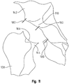
- THA involves the removal of a portion of the patient's femur 108, including the femoral ball and a portion of the femoral neck, as well revision of the acetabulum 110.
- the femoral bone removal and acetabulum reaming accommodates a femoral implant 112 and an acetabular implant 114.
- the femoral implant 112 will include a femoral stem 116 that is received within the intramedullary canal of the patient's femur, as well as a femoral neck 118 interposing a femoral ball 120.
- the femoral ball 120 is received within an acetabular cup insert 124 that is received within an acetabular cup 126 mounted to the patient's acetabulum 110.
- the spherical center of the femoral implant 112 does not coincide with the anatomical center 100 of a patient's hip joint 102
- the patient's soft tissue surrounding the femoral ball 120 will attempt, throughout the femoral ball's range of motion, to translate the femoral ball around the anatomical spherical center 100 of the hip joint 102.
- this motion of the femoral ball 120 induced by the surrounding soft tissue, which does not coincide with the implanted spherical center 104 induces shear forces that were not present in the patient's natural hip joint.
- these shear forces will induce a moment attempting to pivot the femoral ball 120 with respect to the acetabular cup insert 124, instead of rotating it within the acetabular cup insert that would mimic natural motion of the femur 108 with respect to the acetabulum 110.
- a surgeon's inability to properly position the femoral ball 120 and the acetabular cup insert 124 to replicate the anatomical spherical center during THA is a major concern. Even a small offset of less than 1.0 mm may lead to an inducement of shear forces between the femoral ball 120 and the acetabular cup insert 124.
- the implanted hip attempts to rotate around the anatomical spherical center, leading to an induced moment with respect to the anatomical sphere center, further inducing undesirable shear forces.
- common wear patterns have been observed superolateraly in polyethylene acetabular cup inserts removed from patients during a subsequent hip surgery.
- soft tissue surrounding the femoral implant 112 influences the motion of the femoral ball 120, rotating around the anatomical center of the natural hip joint and that this influenced motion causes more than 95% of all hip replacements to experience separation between the femoral ball 120 and the acetabular cup insert 124.
- this influenced motion of the femoral ball 120 may be the primary reason for dislocation of the femoral ball 120 from the acetabular cup insert 124.
- surgeons initially cut the neck 144 of the femur 108 and detach the femoral head 138 from the acetabulum 110. Then, the surgeon reams out the acetabulum 110, without guides and/or knowledge of the original orientation of the anatomical acetabulum sphere. Thereafter, the surgeon prepares the femur for insertion of the prosthetic femoral stem 116. Unfortunately, no technology is used to maintain the anatomical concentric spheres as the acetabular and femoral components are inserted into the bone (femur and pelvis) separately and then the femoral head is "popped" into place with the acetabular cup.
- numerous methodologies may be used to locate the anatomical spherical center of the hip joint, which can include computer assisted surgery, differing imaging modalities such MRI, CT, fluoroscopy, ultrasound, x-rays, and utilization of bone pin markers or other marker techniques, as well as utilization of an intra-operative jig or guide.
- Some concerns associated with certain of these techniques include, without limitation: (1) the imaging techniques and computer assisted surgery are pre-operative and require the surgeon to do pre-operative planning; (2) the techniques induce added time and complexity to the surgery; (3) the techniques add significant expense to the surgery; and (4) the techniques have an inherent error that would not permit the surgeon to accurately find the anatomical center of the hip joint.
- a novel technique and associated instruments for finding and maintaining the anatomical center of the hip joint includes utilization of a novel trial component allowing a surgeon to more easily find the anatomical center of the hip joint and to position the implanted components to mimic the anatomical center of the hip joint.
- This exemplary technique does not add significant additional time or money to the THA procedure, does not require pre-operative planning using an imaging modality, and does not require the surgeon to learn how to use a software package associated with a computer assisted surgical technique.
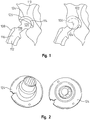
- the surgeon will assess the orientation and shape of the patient's natural femoral head 138 with respect to the pelvis 142 and locate the spherical center of the hip joint, as shown in FIG. 3 .
- the spherical center of the hip joint may be located using many different techniques. But locating the spherical center of the hip joint as described herein will preferably be done without introducing significant extra cost, excessive time, and increased complexity to the surgery.
- the surgeon keeps track of the relative orientation and position of the femur 108 with respect to the pelvis 142, which includes keeping track of the angle of the femoral neck 144 with respect to landmarks defined on the pelvis and noting distances between the femur and the pelvis at various points that are introduced by the surgeon, but not necessarily specific.
- the surgeon marks at least four points 148 (two on the femur 108 and two on the pelvis 142) on the two bones comprising the hip joint and records two distance measurements between corresponding sets of points, identified in FIG. 4 as distance A and distance B.
- more than four points 148 may be used to establish more than two distance measurements between the pelvis and femur.
- the points 148 may comprise physical or virtual pins or markers inserted into or otherwise mounted to the respective bone.
- one or more pins or markers 150 may be mounted to the femur 108 and/or pelvis 142 to record anatomical angles, such as anteversion of the femoral ball and femoral neck with respect to the acetabulum. After the distance measurements and angular measurements have been taken, any pins or markers previously mounted to the femur and pelvis may be removed. But it is preferred that any mounting location be preserved for later attachment of the pin or marker.
- each pin may be removed but its associated sleeve, having a slightly larger or smaller radius than the pin or marker, will be maintained within the respective bone. This retained sleeve within the bone allows each pin to be replaced at any time.
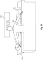
- a surgeon has a laser or some other light beam instrument above the operating room table.
- the use of light beams provides a relatively easy, less expensive, and much less complicated alternative to computer assisted orthopaedic surgery.
- an even further alternative method makes use of a laser or other light beam instrument 300 above the operating table 302 to record the orientation and position of the femur 108 and the pelvis 142 (specifically, the acetabulum 110) prior to joint separation and before any bone cuts are made.
- lasers are presently used in other industries like land development and carpentry and even in your home to hang a picture on the wall, the instant inventor is unaware of lasers being used during a surgical procedure to aid in bone cuts and implantation of prosthetic components. These lasers, for other industries, could be purchased off the shelf, but for the medical application discussed in this patent, a specialized instrument is disclosed.
- a laser is a device that emits light (electromagnetic radiation) through a process of optical amplification based on the stimulated emission of photons.
- the term "laser” originated as an acronym for Light Amplification by Stimulated Emission of Radiation.
- the emitted laser light is notable for its high degree of spatial and temporal coherence, unattainable using other technologies. Spatial coherence typically is expressed through the output being a narrow beam which is diffraction-limited, often a so-called a "pencil beam.”
- Laser beams can be focused to very tiny spots, achieving a very high irradiance. Or laser beams can be launched into a beam of very low divergence in order to concentrate its power at a large distance.
- Temporal (or longitudinal) coherence implies a polarized wave at a single frequency whose phase is correlated over a relatively large distance (the coherence length) along the beam.
- a beam produced by a thermal or other incoherent light source has an instantaneous amplitude and phase which vary randomly with respect to time and position, and thus a very short coherence length.
- Most so-called "single wavelength" lasers actually produce radiation in several modes having slightly different frequencies (wavelengths), often not in a single polarization.
- temporal coherence implies monochromaticity, there are even lasers that emit a broad spectrum of light, or emit different wavelengths of light simultaneously. There are some lasers that are not single spatial mode and consequently these light beams diverge more than required by the diffraction limit. However all such devices are classified as “lasers” based on their method of producing that light: stimulated emission.
- a laser beam or light source is focused to very small spots on the bone or very thin lines representing anatomical landmarks and/or bone or implant component angles.
- lasers are presently used for eye surgery, the application for this invention is quite different.
- the present invention does not use light to ablate or make any cuts in tissue. Rather, the light is utilized to create virtual jig or cutting guide.
- one or more laser or light beam sources or generators is housed in a projection device 300 above the operating room table 302 (see FIG. 18 ).
- the main use of lasers in other industries is to project a laser "beam”. For purposes of the instant application, what is projected is a laser "line” or laser "shape”.
- the projection device 300 also includes a shutter or a variable opening so that a line of light may be created having a variable distance, on the order of 1.0 mm to 50 cm, and be projected onto the anatomical or implanted structure.
- this line may be used to define anatomical axes, such as the mechanical axes, which might require this projected laser line to be 2.0 meters in length.
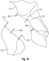
- Exemplary lines of light are shown in FIG. 5 .
- the thickness and distance of these light lines may be modified using the shutter or variable opening. In this manner, the surgeon is able to control the thickness of these lines using controls communicatively coupled to the projection device 300.
- the controls incorporate a voice recognition module in order to allow the surgeon to change the line thickness, distance, and/or orientation by verbal commands.
- the projection device 300 is not limited to projecting lines of light. Rather, the projection device 300 is also operative to project shapes (2D and 3D) including, without limitation, images replicating physical jigs and cutting guides.
- a surgeon uses a light beam instrument 300 to orient a beam of light in a line ("light line") to appear on the femoral neck 144.
- the light beam instrument 300 allows the surgeon to rotate and translate this light line until the line appears, for example, in the middle of the femoral neck 144 or other locations with respect to the femoral neck that mimic the proper rotation of the femoral neck with respect to the pelvis 142.
- the surgeon mounts two pins 152 (also marked as "C” and "D”) onto the pelvis 142 and the femur 108, passing through the light line, to allow the proper neck angle rotation to be defined at anytime.
- the surgeon could record the distance between the corresponding pins, but this is not necessary when only assessing the orientation of the neck angle.
- the surgeon may utilize the light beam instrument 300 to position additional pins 152 (marked, "A”, “B”, “E”, “F") if needed by the surgeon. Accordingly, at anytime during the THA procedure, even if the femur 108 has been re-oriented many times with respect to the pelvis 142, the surgeon is able to re-orient the femur 108 with respect to the pelvis 142 and recreate any of the lines (marked, "L1", “L2”, “L3”) by turning on the light beam instrument 300 and aligning the pins 152 with respect to the light line.
- the instant application describes the use of a light beam instrument with respect to total hip arthroplasty surgery, it should be noted that the light beam instrument may be used directly in surgical joint replacement or revision procedures, in addition to any form of procedure beyond joint replacement or revision.
- the shape of the femoral head 138 is recorded in order to locate the anatomical spherical center of the hip joint. Recordation of the shape of the femoral head 138 can be accomplished in numerous ways.
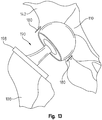
- a first method of recording the shape of the femoral head 138 is to use a series deformable plates 154 (four plates, for example) that are curved and/or spherical and repositionable along pins/rods 156 in order to wrap the deformable plates around the femoral head by compressing the plates against the femoral head using dials on a trial instrument that remains in contact with all of the plates and allows the surgeon to translate and orient the plates specifically on the surface of the femoral head.
- four plates are used, each representing one quadrant of the surface area of the femoral head. These plates may be disposable or re-usable and one or more of these plates may be securely fastened to a guided instrument (not shown).
- This guided instrument may have dials and levers that allow each plate to be translated to/from the bone surface and re-oriented on the bone surface. Therefore, the surgeon can translate and/or orient the plates towards the end of the femoral head and away from the pins/rods. Once the plates 154 are compressed against the femoral head 138, the orientation, size and angularity of the femoral head can be recorded. Depending on which femoral implant ball size a surgeon chooses, alternative plates 154 having a predefined curvature could be fixated to the pins/rods 156 and dialed in either separately or simultaneously to record the appropriate orientation, size and angularity of the femoral head.
- each of the plates 156 may be independently repositionable, it is also within the scope of the invention to have the plates repositioned in unison or systematically repositioned until the plates come in contact with the femoral head 138.
- the exact location of the spherical center of the hip joint can be located before the femoral head and neck 144 are removed from the femur.
- trial components used in THA are not aligned with one another. Instead, the surgeon routinely places the acetabular component and the femoral component in place without aligning these components with each other.
- the instant invention may make use of one or more trial components during surgery that is/are aligned according to the spherical center of the patient's natural hip joint being replaced or revised.
- the THA trial components may be either a single piece or multiple pieces and allow the trial femoral head to be securely placed into the acetabular trial component. This interaction between the trial femoral head and acetabular trial component allows the femoral head to freely rotate and be "popped" into place by inserting the head into the acetabular trial component.
- the trial components may be generic, or have limited applicability (gender or race specific), or be patient-specific.
- the trial components may be reusable or may be disposable.
- the instant invention may make use of an anatomical sphere interposing the femoral neck and pelvis in order to replicate the size and spherical curvature of at least one of the patient's femoral head bearing surface and acetabular cup bearing surface as a means to utilize a single sphere necessarily having one central point. More specifically, the correct acetabulum sphere is one whose anatomical femoral head sphere surface maintains contact with the weight-bearing portion during gait of the anatomical acetabulum sphere. Referencing FIG.
- a surgeon uses a cutting guide 160 replicating the spherical shape of the patient's natural femoral head 138.
- guides are routinely used make bone cuts.
- guides are not routinely used.
- This cutting guide 160 is mounted onto the femur 108 and provides for a spherical or uniform arcuate cut of the femur that removes the natural femoral head 138 and any potentially a portion of the femoral neck 144.
- the guide could be mounted onto the femur 108 using a clamp, pins, as, or another method for fixating the guide to the femur.
- the surgeon could change the size and shape of the circumference of the cutting guide by using a dial on the handle.
- the guide is fixated to the femur 108.
- this cut could also be straight perpendicular to axis through the femoral head, passing through the center of femoral neck. This cut may be of any shape, but it is advantageous that this cut be spherical in its arc.
- a cut to the proximal femur 108 is made to remove the femoral head 138 and a portion of the femoral neck 144.
- the surgeon can visually inspect the femoral head and view its curvature.
- a measuring instrument that measures the femoral head circumference and/or diameter and/or shape, the surgeon could then choose the proper femoral head guide.
- the measurement of the femoral head may be made with a measurement device, a digital recording device, or an instrumented jig that is placed on the femoral head, possibly in the shape of the jig in FIG.
- the proximal femur 108 includes an arcuate depression 164 that is sized to receive a sphere.
- the cut into the proximal femur 108 may be spherical, or the cut may have a constant arcuate profile from anterior to posterior. This constant arcuate profile has a uniform cross section from anterior to posterior, unlike the spherical cut, but is nonetheless operative to receive a prosthetic trial sphere given that the arcuate cut has the same radius as would be used for making a spherical cut into the femur.
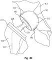
- a positional guide 170 according to the invention and having a spherical shape is inserted into the acetabulum 110 and positioned in contact with the femoral neck 144.
- the spherical shape is comprised of two semispherical sections mounted to one another and removable from one another.
- a series of holes are drilled through a series of tabs 182 (using the tabs as an axial guide for the holes) that extend radially outward from the exterior of the proximal semispherical section and into the acetabulum 110.
- the surgeon can re-orient the guide until the position and orientation matches with the position and orientation of the femoral head that was removed.
- This guide could be a perfect sphere in shape, or the inner portion of the guide could be of a shape that is anatomical with respect to the acetabulum or the inner portion of the sphere could be just a rim inserts only a small amount into the acetabulum.
- the inner portion of this sphere may take on any shape, as long as it is inserted into the acetabulum, but it may be advantageous for this shape to be spherical or anatomical.
- the outer portion of the guide be spherical to mate with a spherical cut in the proximal femur, it should be understood that the outer portion may be of any shape.
- the outer portion may have a box-like shape where the outer edge may be in contact with a straight cut on the femur. If a box-like shape is used, it is preferable for the surgeon or another to measure the diameter along the three principal axes, to ensure that the box is shaped to mimic the circumference and diameters of the femoral head.
- a series of pins 180 are inserted (one pin for each hole) through the tabs 182 and into the holes in the acetabulum 110, thereby locking the guide 170 in position with respect to the acetabulum.
- the guide 170 is removed and a reamer (not shown) is used to ream the acetabulum 110 using the pins 180 as alignment guides.
- a reamer (not shown) is used to ream the acetabulum 110 using the pins 180 as alignment guides.
- more rigid guide pins may be used to guide the reamer, or the guide pins may be used to insert a central guide pin, thereby allowing the reamer to ream out the acetabulum along the central principal axis of the acetabulum sphere.
- the inner portion of the femoral head guide is either spherical or anatomical in shape so that when the outer portion is removed, the inner portion is reminiscent of an acetabular cup so the surgeon could visible inspect the position and orientation of the femoral head guide cup, which will ultimately be the position and orientation of the implanted cup after all the final acetabulum cuts are made.
- the guide 170 may be aligned, primarily off of the proximal femur and inserted into the acetabulum. Likewise, if the proximal femur is damaged, the guide 170 may be aligned more so off of the acetabulum and then inserted next to the proximal femur.
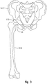
- a portion of a prosthetic trial 190 is inserted within the acetabulum 110 using the pins 180 as alignment guides.
- the size of the spherical head in this trial 190 may be variable in size and shape depending on how much bone and/or cartilage was removed during the reaming process.
- this prosthetic trial 190 includes an acetabular component 192 and a femoral ball 194 inserted therein. It is the acetabular component 192 that is temporarily inserted into and mounted to the reamed acetabulum 110.
- the femoral ball 194 of the trial 190 is coupled to a femoral neck 196 having an endplate 198.
- trials 190 may be modular so that the femoral ball 194 is repositionable with respect to the acetabular component 192 and/or the femoral neck 196 is repositionable with respect to the endplate 198.
- the trials 190 may be integrated or a single piece to inhibit movement between the respective components so that the orientation and position of the femoral ball 194 with respect to the acetabular component 192 is fixed and/or the orientation and position of the femoral neck 196 with respect to the endplate 198 is fixed.
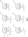
- the trails 190 may embody a neutral shape position (A) or have a thicker base (B), or have variable neck lengths (C), or have an irregular base shapes (D), or have a clockwise rotated base shape (E), or have a counterclockwise rotated base shape (F).
- the various trials 190 may be temporarily mounted to the acetabulum 110 and aligned using the pins 180 to maintain proper acetabular cup orientation.
- the femoral aspect of the trial 190 is used by the surgeon to properly maintain the orientation and position of the femur 108.
- the trial 190 After the orientation and position of the femur 108 is fixed with respect to the pelvis 142 using the trial 190, guide pins 200 inserted through the femoral endplate 198, allowing for proper cuts to be made, maintaining concentric anatomical spheres.
- the femoral portion of this trial 190 may be free to rotate around all three axes or a locking mechanism may be used so that when the proper orientation of the femoral neck coincides with anatomical femoral neck, the angle is locked into place.
- the surgeon is ready to mark the final cut of the femoral neck 144 using the trial 190.
- the trial 190 which is mounted to the pelvis 142, the resulting mark for the final cut of the proximal femur 108 accounts for the orientation and position of the trial and allows concentric spheres (anatomical acetabulum sphere and femoral sphere) to be maintained. Although it is shown in FIGS.
- the trial 190 rests on the proximal femur, it could also be inserted into the proximal femur and/or guided around the proximal femur.
- the trial 190 is removed from both the femur 108 and the pelvis 142.
- a cutting guide (not shown) is mounted onto the femur 108 using the pins 200 as a guide to ensure the alignment of the eventual femur cut.
- Various tapers may also be implemented in this trial shown in FIG. 12 . Therefore, when the acetabular cup portion of the trial is inserted into the acetabulum, it may be temporarily fixed into place using nails or other fixating devices. Then, the femoral portion of the trial may be fixated to the superior aspect of the femur. Next, the surgeon may manipulate the leg into multiple positions, visually inspecting and instrumentally measuring for impingement, possible dislocation and any other concerns that could be raised. The surgeon may then replace the femoral portion of the trial using a different taper to again inspect and measure how the femoral component is rotating with respect to the pelvis.
- a distraction device may also be used that measures the amount of pull of the acetabular cup from the bone during manipulation of the femur. If the implants have concentric spheres, then the distractive and shear forces should be very low. If during this manipulation of the femur, the acetabular cup visually attempts to pull away from the bone or if the measurement device(s) detects irregular amounts of distractive or shear forces, a different trial may be used.
- This distraction measurement device may be a spring loaded mechanism or even a measurement device that measures distractive distance and converts this distance to a force, based on a mathematical model of the human hip joint that derives intra-operative forces using Newton's equations of motion.
- the mathematical models of the human body may be derived as an inverse model that measures the three rotations and translations of either the cup from the bone and/or the femoral head from the cup. Then, this motion is entered into the mathematical model to determine the forces in three directions and the torques around three directions.
- an alternate method of marking the femur 108 includes using an alignment/trial instrument 170 positioned so the acetabular portion is seated within the acetabulum and the femoral portion overlies the femoral neck. The surgeon may then reposition the instrument 300 to align with the proper orientation of the intended proximal femoral cut.
- the alignment/trial instruments 170 may be of normal implant shape and thickness 170A, or could of proper shape and thickness for the cup and femoral ball, but much thinner for the femoral neck and proximal femoral component 170B, 170C.
- the femoral neck portion of the alignment/trial instruments 170B, 170C comprises a flat plate that is contoured to approximate the exterior contour of the patient's proximal femur so that the instrument may be easily placed directly on top of the proximal femur to ensure an accurate proximal femoral bone cut.
- the shape could also be anatomical in nature.
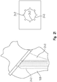
- a further alternative method of marking the femur 108 includes using the light beam instrument 300 previously discussed to superimpose various shapes upon the proximal femur and distal pelvis 142.
- Those skilled in the art will realize the virtually any two dimensional shape could be superimposed upon the proximal femur such as, without limitation, a square, a rectangle, a trapezoid, and an outline of a prosthetic hip trial.
- a computer algorithm may be used with this instrument 300 so that three-dimensional or planer two-dimensional anatomical bone shapes are stored within a virtual library of images. These images may be created using one or more imaging modality including, but not limited to, MRI, CT, ultrasound, and X-rays. These images may also be stored in various libraries for size, gender and ethnicity.
- surgeon uses a handheld instrument to generate surgical data including, but not limited to, boney landmarks, orientations, and distances.
- This surgical data is used by a computer algorithm to initially choose which image in the various libraries best matches the data entered and then, may modify one or more images stored in the virtual library to generate an image using the instrument 300 and project this image onto the patient's anatomical bone (in this case, the proximal femur).
- the library images may then be superimposed onto and compared with various images in the library, may be used to create a bone from various bones, or may be morphed from one or multiple library images.
- the image may be fine-tuned to modify the shape, size, thickness, position, and/or orientation to best match the patient's bone.
- the instrument 300 projects virtual jigs, implants, and/or bones onto the patient's bone representative of the ideal location for each bone cut.
- the instrument may project an image of the final implant or implant component onto the patient's bone.
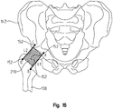
- FIG. 16 depicts a rectangular shape 210 superimposed onto the proximal femur 108 and distal pelvis 142
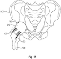
- FIG. 17 depicts an outline of a prosthetic hip trial 212 superimposed onto the proximal femur and distal pelvis.
- the surgeon may turn on the light beam instrument 300 to verify the bone cuts made or to revise the bone cuts to match a particular shape, such as the outline of the intended implant.
- a particular shape such as the outline of the intended implant.
- the surgeon may utilize one or more of the pins 152 to properly orient and position the femur with respect to the pelvis 142.
- the light beam instrument 300 may be utilized to superimpose one or more shapes that represent the best or preferred implanted femoral neck shape and/or acetabular cup and/or femoral head that maintains proper biomechanics and concentric spheres of the pelvis 142 and femur 108.
- This light beam instrument 300 provides a relatively easy, less expensive, and much less complicated alternative to computer assisted orthopaedic surgery. At present, many surgeons are attempting to use computer navigation to define the orientation and position of the hip joint, but this methodology can be cumbersome and difficult to learn.
- a light beam instrument 300 controls (such as dials and/or levers) may be used to change the position and orientation of a light beam (or image) directed from the instrument above the operating room table 302 to represent angles and/or positions of the femur and/or the pelvis during surgery.
- a surgeon can then turn on a light beam from the instrument 300 and manually and/or audibly change the position and/or orientation of the light beam to define an anatomical feature of a bone, such as the anatomical femoral neck.
- a bone such as the anatomical femoral neck.
- two or more pins may be inserted in the femur and/or pelvis. These pins may be used to define the anatomical bone or bone feature in question.
- Multiple light beams may also be used, defining as many bones or boney features as needed by the surgeon. Therefore, at anytime during the surgery, the surgeon may turn on a beam from the instrument 300 and re-orient the bones until the beam passes through the alignment pins.
- the projected images could also be three-dimensional using holographic images.
- Holographic imaging may be utilized to allow bone anatomy, bone landmarks, and implant components to be projected onto the bone using a light source.
- the light source scattered from the object of reference, will be recorded and later reconstructed so that when an imaging system (a camera or an eye) views the reconstructed beam, an image of the bone and/or implant component is seen even when it is no longer present in the surgeon's field of view.
- the image changes as the position and orientation of the surgeon changes in exactly the same way as if the object were still present, thus making the image appear three-dimensional.
- the holographic recording itself is not an image - it consists of an apparently random structure of either varying intensity, density.
- a computer algorithm is used in order to generate a three-dimensional image and superimpose this image onto the requisite one. Unlike the two dimensional image projection, the surgeon will be required to measure distances and orientations in all three directions.
- a series of preexisting three-dimensional images are stored in a virtual library. These images will contain proper bone landmarks and distances that define orientation and position with the human body structure. These images may be rigid or deformable bodies.
- the handheld device is used to define anatomical distances, positions, and orientations on the bone of the patient in question and then, the computer algorithm chooses the best initial three-dimensional bone fit and projects this three dimensional image onto the anatomical bone.
- the computer algorithm chooses the best initial three-dimensional bone fit and projects this three dimensional image onto the anatomical bone.
- distances from the light beam source of the light beam source instrument to the anatomical bone must be known to properly project the three-dimensional image. Without defining this distance, at multiple locations on the anatomical bone, the three-dimensional image may not be properly projected. Therefore, three-dimensional information along all three directions must be measured and entered into the computer algorithm.
- An exemplary method of measuring and entering the data for processing by the computer algorithm includes using a digital camera or other recording source to take multiple photos or images of the boney anatomy, such as the femoral neck and head after the surgeon opens up the joint space. These image views may be proximal, distal, anterior, posterior, medial, and/or lateral. These images, in real-time may be sent to the light beam instrument 300 and using the instant computer algorithm, a three-dimension image, either holographic or non holographic is constructed using the three-dimensional library of bone images. Then, the best fit bone image is projected onto the patient's bone. Using dials, levers or other controls, the three-dimensional image can be re-oriented, re-sized and/or re-positioned onto the anatomical bone. Once the surgeon deems the three-dimensional image to be an accurate representation of the anatomical bone, another algorithm is used to define boney landmarks and bone cuts that are ideal for that particular patient.
- Creating the three-dimensional holographic images makes use of devices that produce so-called diffraction fringes, fine patterns of light and dark that can bend the light passing through them in predictable ways.
- a dense enough array of fringe patterns, each bending light in a different direction, can simulate the effect of light bouncing off of a three-dimensional object.
- one exemplary commercially available technology uses a cylinder approximately one meter high by one-half meter in diameter. Inside the cylinder, a helix spins at high speed. A two-dimensional image is projected onto the helix and then the image is projected onto the bone. It is presumed, for purposes of this example, that the images are simple CAD-like drawings. These simple images are constructed from multiple digital camera images as discussed previously.
- An alternative method and technology that may be used incorporates a pair of lasers that emit beams that intersect one another inside of a cube of special material. The material inside the cube glows at the intersection point. Another method uses two lasers that intersect inside a cube of a special material. The material glows at the intersection, creating an image that may then be projected onto the bone.
- the surgeon points the laser of the light beam instrument 300 at a beam splitter, thereby causing the beam to be divided into two beams.
- Mirrors within the light beam instrument 300 are constructed along the path of the splitter so that the laser hits the bone in question.
- the light beam instrument 300 also includes diverging lenses in front of the mirrors so that the two beams passing through them become wide swathes of light rather than regular beams.
- One of the lights (object beam) will reflect off the bone in question and onto the holographic plate of the light beam instrument 300.
- the other light (reference beam) will hit the holographic plate only.
- the surgeon projects the three-dimensional holographic image on the bone in question at anytime during surgery.
- surgeons routinely have four to ten trays of instruments and jigs for use during the surgery. Before every surgery, these instruments and jigs need to be prepared and sterilized.
- the foregoing light beam instrument may be used to project these instruments and jigs onto the bone, as needed by the surgeon.
- Each instrument is scanned using a laser scanner or is converted into three-dimensional solid objects using three-dimensional computer models.
- the images may be re-oriented and displayed at anytime using a computer algorithm that instructs the light beam instrument to rotate and translate with respect to either a fixed or relative reference frame.
- the Newtonian reference frame is defined within the computer algorithm and relative reference frames are defined for each instrument.
- Each rotational and translational direction is defined as a function in an inverse direction model or as a generalized speed in a forward solution model.
- a change in direction or rotation of the displayed image may be made by the surgeon audibly, through the use of dials and/or levers (i.e., controls) or using a touch screen monitor.
- numerical changes to the translation matrix may also be input to define motion changes.
- a touch screen instrument the surgeon is able to touch a picture of a virtual instrument or guide and the computer algorithm instructs the light beam instrument to project it. Then a secondary library appears on the screen, whereas a surgeon can choose the correct size of the image.
- the image whether two-dimensional or three-dimensional can be repositioned. Therefore, the relative transformation matrix between the instrument and the Newtonian reference frame could be altered depending on where the instrument is in space with respect to the origin within the Newtonian reference frame.
- a stop is instituted and the relative reference frame of the instrument with respect to the Newtonian reference frame is recorded and stored for future use of the instrument. Therefore, within the computer algorithm the generalized coordinated and generalized positions, defined from the generalized speeds are changed and redefined based on global coordinate changes. This procedure may be conducted for each instrument, jig and bone, whether in two-dimensions or three-dimensions. These instruments, jigs and bones may have points, axes and cutting guides defined and positioned properly for surgical use.
- this process may be used for three-dimensional images, holographic or non-holographic.
- holography is a technique that allows the light scattered from an object to be recorded and later reconstructed so that it appears as if the object is in the same position relative to the recording medium as it was when recorded.
- the image changes as the position and orientation of the viewing system changes in exactly the same way as if the object was still present, thus making the recorded image (hologram) appear three dimensional.
- Holograms can also be made using other types of waves.
- Three-dimensional space is a geometric model of the physical universe in which we live.
- the three dimensions are commonly called length, width, and depth (or height), although any three mutually perpendicular directions can serve as the three dimensions.
- Cartesian geometry describes every point in three-dimensional space by means of three coordinates. This is the process previously described for positioning and orienting instruments, jigs and bones for surgical use. Three coordinate axes are given, each perpendicular to the other two at the origin, the point at which they cross.
- the instant inventor is a user of Kane's Dynamics.
- each body or massless frame that is defined is assigned three unit vectors (or relative axis), labeled as either the 1, 2 or 3 axis within a particular reference frame.
- the position of any point in three-dimensional space is given by an ordered triple of real numbers, each number giving the distance of that point from the origin measured along the given axis, which is equal to the distance of that point from the plane determined by the other two axes.
- the created three dimensional holographic images may be constructed using generators and/or other components purchased from companies within the "International Hologram Manufacturers Association" ( www.ihma.org ), specifically companies such as "The Hologram Company” (sales@thehologramcompany.co.uk ) and "API Holographics” ( www.apigroup.com ). If one chooses to go this route, components and even full holographic projectors may be commercially purchased.
- the holographic projector or holographic components are used with a digital device, instrumentation, and computer algorithms to create the images, as well as size, position, and orient the images into the proper location during surgery.
- a specialized holographic projector may be fabricated from commercially available components and ensuring that the resolution and quality of the holographic images is ideal for medical use.
- each light beam or point within the holographic image is defined with respect to the fixed Newtonian reference frame, defined on the light beam instrument. Unlike moving a two-dimensional image, two processes may be used to move the holographic image.
- each point could be defined and then redefined with respect to the origin in the Newtonian reference frame, or at least three points within the holographic image could be defined with respect to the Newtonian reference frame and then three relative axes with the holographic relative reference frame could be constructed and these axes could be oriented and positioned with respect to the Newtonian reference frame.
- the relative transformation matrix will be redefined. Once the three-dimensional image is positioned in place by the surgeon, the coordinates for this relative transformation matrix are locked in place and may be used at anytime during the surgery by the surgeon.
- each of the three points is defined as P1, P2 and P2 on a three dimensional image taking the shape of an ellipse in any view or an elongated sphere.
- the point O represents a fixed point in the Newtonian reference frame, within the light beam instrument or where the holographic image project is housed in the instrument.
- the image that is being projected is defined as body A and a relative reference frame with the unit vectors A1>, A2> and A3> are defined.
- a 1 > P_P 2 _P 1 > P_P 2 _P 1
- Unit vector A1> is defined by creating a line using the points P1 and P2 and the dividing this line by its magnitude.
- the second unit vector is defined by cross multiplying vector A1> with the unit vector of the line between points P2 and P3 and dividing this function by its magnitude.
- a 2 > UnitVEC P_P 2 _P 3 > ⁇ A 1 > UnitVEC P_P 2 _P 3 > ⁇ A 1 >
- the third unit vector A3> is defined by cross multiplying A1> and A2>.
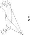
- the transformation matrix can be derived using three successive rotations defined in FIG. 26 , whereas the reference frame A represents a body, but the A' and A" reference frames are intermediate in nature and are defined as massless reference frames.
- ⁇ 1, ⁇ 2 and ⁇ 3 represent relative rotations of the three dimensional image with respect to the light beam instrument and as these angles changes, so does the three dimensional image. These angles may be previously defined before surgery, may equate to temporal or depended functions or may be changed intraoperatively either using dials and/or levers, audibly or through another measurement device.
- PA 11 C ⁇ 1 ⁇ C ⁇ 3 ⁇ S ⁇ 1 ⁇ S ⁇ 2 ⁇ S ⁇ 3
- PA 12 S ⁇ 1 ⁇ C ⁇ 3 + S ⁇ 2 ⁇ S ⁇ 3 ⁇ C ⁇ 1
- PA 13 ⁇ S ⁇ 3 ⁇ C ⁇ 2
- PA 21 S ⁇ 1 ⁇ C ⁇ 2
- PA 22 C ⁇ 1 ⁇ C ⁇ 2
- PA 23 S ⁇ 2
- PA 31 S ⁇ 3 ⁇ C ⁇ 1 + S ⁇ 1 ⁇ S ⁇ 2 ⁇ C ⁇ 3
- PA 32 S ⁇ 1 ⁇ S ⁇ 3 ⁇ S ⁇ 2 ⁇ C ⁇ 1 ⁇ C ⁇ 3
- PA 33 C ⁇ 2 ⁇ C ⁇ 3
- three-dimensional images references holographic or non-holographic images, these images could quite easily be constructed using any technique for defining and creating three-dimensional images.
- application for three dimensional images is disclosed in the context of total hip arthroplasty, however, those skilled in the art should understand that these three dimensional images and associated equipment could also be used for any joint, organ or structure within the human and animal body and could be used for other surgeries besides just total joint surgeries.
- the final femoral and acetabular implants are mounted to the pelvis 142 and the femur 108.
- Mounting of the final femoral implants may utilize the guide pins 200 or virtual instrumentation through the use of the light beam source instrument. For example, presuming any prefatory reaming of the intramedullary canal of the femur has taken place (and this reaming can also utilize the guide pins 200 for alignment), the final implanted femoral stem 220 is inserted into the intramedullary canal of the femur 108 using the guide pins 200.
- the final femoral neck 224 and femoral ball 226 are mounted to the implanted femoral stem 220.
- the femoral stem 220 includes an endplate 222 that sits upon the outer proximal surface of the femur 108.
- the femoral neck 224 also includes an endplate 228 that couples to the endplate 222 of the femoral stem to mount the neck to the stem.
- the femoral stem 220 is offset from the femoral neck 224. While an offset between the stem 220 and neck 224 may occur infrequently, it has been shown to document the ability to reposition the neck independent from the stem and the modularity of this exemplary implant. In some cases, however, the final implant will be integrated or a single piece so that variable orientation and position of the stem 220 with respect to the neck 224 is not possible.
- the final acetabular implants may be mounted to the pelvis 142 utilizing the guide pins 180.
- the final implanted acetabular cup and cup insert 232 are inserted into the reamed acetabulum 110 using the guide pins 180.
- Presuming the final acetabular cup and cup inserts are modular, minor modifications can be made to the orientation and position of each component with respect to the other. After both the final femoral and acetabular components are implanted and secured, the femoral ball 226 is seated into the acetabular cup insert 232.
- a femoral sleeve 240 for insertion into the intramedullary canal of the femur 108.
- the sleeve 240 may be either press fit into the femur 108 or cemented.
- current techniques commonly cement or press fit the femoral implant into the femur 108.
- This femoral sleeve 240 may be designed with internal grooves and projections 242 so that a femoral stem 220 (see FIG. 19 ) may be inserted into the sleeve at multiple angles.
- the sleeve could also be smooth without grooves. If grooves are used, these grooves and projections 242 may alternate or include a pattern that coincides with a pattern on the femoral stem 220 to ensure proper orientation of the femoral stem with respect to the sleeve. The implanted femoral stem 220 is locked into place within the sleeve 240.
- a sleeve 240 to interpose the femur 108 and the femoral stem 220, it provides the advantage that if the femoral stem needs to be removed for any reason, the femoral stem can be unlocked from the sleeve and then removed without causing additional damage to the intramedullary canal. Thereafter, a new or revised femoral stem may be inserted into the sleeve 240. Accordingly, the use of a permanent sleeve 240 ensures that initial femoral stem alignment is maintained in any femoral version surgery.
- the femoral implant in this in this patient may be removed and then the version angle may be changed and thereafter the femoral stem is re-positioned back into the sleeve.
- the sleeve 240 has been described as having a fixed orientation and position with respect to the femur 108, it is also within the scope of the invention for the sleeve 240 to include mobile bearing functionality. This functionality may be the result of a pair of sleeves that are telescopic, with the inner (smaller diameter) sleeve including the internal grooves and projections 242. This structure allows the inner sleeve to rotate with respect to the femur 108 and may be limited to retard a fully 360 degrees of femoral stem rotation.
- Another alternative includes a sleeve that has no internal grooves and does contain a locking mechanism.
- the sleeve may be cemented and/or press fit into the femur.
- the femoral stem may be locked in one direction so that it can be removed from the sleeve, but is free to rotate around its longitudinal axis or any defined axis that is necessary to maintain concentric spheres.
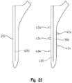
- the femoral stem 390 has an internal longitudinal screw (or gear mechanism) 400.
- the surgeon can turn the screw 400 on the superior aspect of the femoral stem, which will force elements 404 to protrude from the stem into the bone, leading to greater fixation of the femoral stem to the bone. If for some reason the implant needs to be removed during revision surgery, the surgeon can turn the screw 400 in the opposite direction, which operates to pull the elements 404 back into the stem 390 allowing for the stem to be more easily removed. If the femoral stem is to be inserted into the femoral sleeve 240 (see FIG.
- the surgeon turns the screw 400 to reposition the elements 404 to protrude away from the stem into grooves 242 in the sleeve.
- the elements 404 may take on various shapes and sizes and be located at various positions along the femoral stem and/or sleeve 240.
- the elements 404 take on a triangular profile in FIG. 22
- the elements take on a rectangular profile in FIG. 23 .
- the femoral stem and femoral sleeve may take on any number of shapes both on the interior and exterior.
- the inside of the femoral sleeve may be elliptical, while the exterior of the femoral stem is rectangular.
- the exterior of the femoral sleeve may be rectangular, elliptical, or any other cross-section.
Landscapes
- Health & Medical Sciences (AREA)
- Life Sciences & Earth Sciences (AREA)
- Surgery (AREA)
- Orthopedic Medicine & Surgery (AREA)
- Engineering & Computer Science (AREA)
- General Health & Medical Sciences (AREA)
- Biomedical Technology (AREA)
- Heart & Thoracic Surgery (AREA)
- Veterinary Medicine (AREA)
- Public Health (AREA)
- Animal Behavior & Ethology (AREA)
- Oral & Maxillofacial Surgery (AREA)
- Transplantation (AREA)
- Nuclear Medicine, Radiotherapy & Molecular Imaging (AREA)
- Medical Informatics (AREA)
- Molecular Biology (AREA)
- Dentistry (AREA)
- Vascular Medicine (AREA)
- Cardiology (AREA)
- Physical Education & Sports Medicine (AREA)
- Prostheses (AREA)
- Surgical Instruments (AREA)
Priority Applications (1)
| Application Number | Priority Date | Filing Date | Title |
|---|---|---|---|
| EP17163940.4A EP3210547A1 (en) | 2011-12-19 | 2012-12-19 | A cutting guide for use with total hip arthroplasty |
Applications Claiming Priority (2)
| Application Number | Priority Date | Filing Date | Title |
|---|---|---|---|
| US13/330,259 US9668745B2 (en) | 2011-12-19 | 2011-12-19 | Anatomical concentric spheres THA |
| PCT/US2012/070607 WO2013096440A1 (en) | 2011-12-19 | 2012-12-19 | Anatomical concentric spheres tha |
Related Child Applications (1)
| Application Number | Title | Priority Date | Filing Date |
|---|---|---|---|
| EP17163940.4A Division EP3210547A1 (en) | 2011-12-19 | 2012-12-19 | A cutting guide for use with total hip arthroplasty |
Publications (3)
| Publication Number | Publication Date |
|---|---|
| EP2793757A1 EP2793757A1 (en) | 2014-10-29 |
| EP2793757A4 EP2793757A4 (en) | 2015-06-24 |
| EP2793757B1 true EP2793757B1 (en) | 2017-04-26 |
Family
ID=48610889
Family Applications (2)
| Application Number | Title | Priority Date | Filing Date |
|---|---|---|---|
| EP12859722.6A Not-in-force EP2793757B1 (en) | 2011-12-19 | 2012-12-19 | Anatomical concentric spheres tha |
| EP17163940.4A Withdrawn EP3210547A1 (en) | 2011-12-19 | 2012-12-19 | A cutting guide for use with total hip arthroplasty |
Family Applications After (1)
| Application Number | Title | Priority Date | Filing Date |
|---|---|---|---|
| EP17163940.4A Withdrawn EP3210547A1 (en) | 2011-12-19 | 2012-12-19 | A cutting guide for use with total hip arthroplasty |
Country Status (8)
| Country | Link |
|---|---|
| US (3) | US9668745B2 (enExample) |
| EP (2) | EP2793757B1 (enExample) |
| JP (1) | JP6049754B2 (enExample) |
| KR (1) | KR101996848B1 (enExample) |
| CN (2) | CN107669305A (enExample) |
| AU (3) | AU2012359009B2 (enExample) |
| CA (2) | CA2859510C (enExample) |
| WO (1) | WO2013096440A1 (enExample) |
Families Citing this family (19)
| Publication number | Priority date | Publication date | Assignee | Title |
|---|---|---|---|---|
| US9023112B2 (en) | 2011-02-24 | 2015-05-05 | Depuy (Ireland) | Maintaining proper mechanics THA |
| US9167989B2 (en) * | 2011-09-16 | 2015-10-27 | Mako Surgical Corp. | Systems and methods for measuring parameters in joint replacement surgery |
| US9668745B2 (en) | 2011-12-19 | 2017-06-06 | Depuy Ireland Unlimited Company | Anatomical concentric spheres THA |
| EP2854701B1 (en) * | 2012-06-05 | 2018-03-21 | Corin Limited | Guide with guide indicia generation means |
| US8858645B2 (en) | 2012-06-21 | 2014-10-14 | DePuy Synthes Products, LLC | Constrained mobile bearing hip assembly |
| US9427322B1 (en) * | 2012-06-27 | 2016-08-30 | Signal Medical Corporation | Hip implant |
| US12042250B2 (en) | 2013-11-15 | 2024-07-23 | The Regents Of The University Of California | Compositions, devices and methods for diagnosing heart failure and for patient-specific modeling to predict outcomes of cardiac resynchronization therapy |
| JP6480694B2 (ja) * | 2014-09-30 | 2019-03-13 | 京セラ株式会社 | 手術支援装置およびプログラム |
| EP3337429B1 (en) * | 2015-08-21 | 2023-02-15 | HIP Innovation Technology, LLC | Surgical trays and instruments for implanting a hip replacement prosthesis |
| CA3006777A1 (en) | 2015-12-22 | 2017-06-29 | The Regents Of The University Of California | Computational localization of fibrillation sources |
| CN116650106A (zh) | 2016-03-14 | 2023-08-29 | 穆罕默德·R·马赫福兹 | 用于无线超声跟踪和通信的超宽带定位 |
| JP2018028630A (ja) * | 2016-08-19 | 2018-02-22 | アーゼッド・エレクトロニック・マテリアルズ(ルクセンブルグ)ソシエテ・ア・レスポンサビリテ・リミテ | ブラックマトリックス用組成物、およびそれを用いたブラックマトリックスの製造方法 |
| CA3034071A1 (en) * | 2016-08-30 | 2018-03-08 | Mako Surgical Corp. | Systems and methods for intra-operative pelvic registration |
| CN106344151B (zh) * | 2016-08-31 | 2019-05-03 | 北京市计算中心 | 一种手术定位系统 |
| US20190333639A1 (en) | 2018-04-26 | 2019-10-31 | Vektor Medical, Inc. | Generating a model library of models of an electromagnetic source |
| CN112639998A (zh) * | 2018-07-05 | 2021-04-09 | 加利福尼亚大学董事会 | 解剖结构与体表电极定位的计算模拟 |
| US11103367B2 (en) | 2019-02-15 | 2021-08-31 | Encore Medical, L.P. | Acetabular liner |
| WO2022056221A1 (en) * | 2020-09-10 | 2022-03-17 | Dignity Health | Systems and methods for volumetric measurement of maximal allowable working volume within a surgical corridor |
| EP4453959A1 (en) * | 2021-12-23 | 2024-10-30 | Koninklijke Philips N.V. | Methods and systems for clinical scoring a lung ultrasound |
Family Cites Families (135)
| Publication number | Priority date | Publication date | Assignee | Title |
|---|---|---|---|---|
| US3510883A (en) | 1967-10-30 | 1970-05-12 | Robert F Cathcart | Joint prosthesis |
| CA912202A (en) | 1969-03-13 | 1972-10-17 | V. Chambers Harold | Artificial hip joint |
| SE344706B (enExample) | 1970-08-21 | 1972-05-02 | Moelnlycke Ab | |
| GB1447044A (en) | 1972-11-16 | 1976-08-25 | Nat Res Dev | Endoprosthetic bone joint devices |
| FR2260980B1 (enExample) | 1974-02-20 | 1976-12-03 | Herbert Jules | |
| US4024588A (en) | 1974-10-04 | 1977-05-24 | Allo Pro A.G. | Artificial joints with magnetic attraction or repulsion |
| CH593053A5 (enExample) | 1975-06-03 | 1977-11-15 | Sulzer Ag | |
| GB1573608A (en) | 1976-12-22 | 1980-08-28 | Howse & Co Ltd D | Prosthetic hip cup assembly |
| US4068324A (en) | 1977-01-19 | 1978-01-17 | Bio-Dynamics Inc. | Platform supported hip prosthesis |
| US4318191A (en) | 1980-08-13 | 1982-03-09 | Massachusetts Institute Of Technology | Compliant head femoral endoprosthesis |
| DE3147707A1 (de) | 1981-05-18 | 1982-12-23 | Mecron Medizinische Produkte Gmbh, 1000 Berlin | Teil einer hueftgelenkprothese |
| IE55242B1 (en) | 1982-05-17 | 1990-07-18 | Nat Res Dev | Endoprosthetic bone joint devices |
| US4960427A (en) | 1983-03-08 | 1990-10-02 | Joint Medical Products Corporation | Ball and socket bearing for artifical joint |
| US4955919A (en) | 1983-05-06 | 1990-09-11 | Pappas Michael J | Multi-component joint prosthesis with increased wall flexibility facilitating component assembly |
| US4528980A (en) | 1983-10-19 | 1985-07-16 | Howmedica, Inc. | Acetabulum sizer and drill guide |
| US5047062A (en) | 1984-01-26 | 1991-09-10 | Pappas Michael J | Femoral stem-type prosthesis |
| FR2595562B1 (fr) | 1986-03-13 | 1992-08-28 | Rhenter Jean Luc | Cupule de prothese |
| DE3643815A1 (de) | 1986-12-20 | 1988-06-30 | Mohammad Dr Med Izadpanah | Kopfanordnung fuer eine hueftgelenk-endoprothese |
| AT386948B (de) | 1987-07-09 | 1988-11-10 | Menschik Alfred Dr | Kuenstliches hueftgelenk |
| US5009665A (en) | 1989-02-08 | 1991-04-23 | Boehringer Mannheim Corp. | Acetabular cup |
| FR2679611B1 (fr) | 1991-07-26 | 1993-10-08 | Snr Roulements | Roulement combine radial axial. |
| US6083263A (en) | 1991-08-23 | 2000-07-04 | Draenert; Klaus | Adjustable hip-joint endoprosthesis |
| RU2042345C1 (ru) | 1991-09-24 | 1995-08-27 | Малое производственное внедренческое предприятие "Северный ветер" | Тотальный эндопротез бедра |
| EP0585503B1 (de) | 1992-09-01 | 1998-01-07 | Sulzer Orthopädie AG | Doppelschalige Revisionshüftgelenkpfanne |
| US5326368A (en) | 1992-09-22 | 1994-07-05 | Howmedica, Inc. | Modular acetabular cup |
| CN1076104A (zh) | 1993-01-01 | 1993-09-15 | 王野平 | 带滚动体的人工髋关节 |
| US5443519A (en) | 1993-04-22 | 1995-08-22 | Implex Corporation | Prosthetic ellipsoidal acetabular cup |
| EP0639356B1 (de) | 1993-08-18 | 2000-07-05 | Sulzer Orthopädie AG | Verfahren zur Erzeugung von äusseren Verankerungsflächen an Gelenkimplantaten |
| US5522904A (en) | 1993-10-13 | 1996-06-04 | Hercules Incorporated | Composite femoral implant having increased neck strength |
| US5431657A (en) * | 1994-05-23 | 1995-07-11 | Zimmer, Inc. | Instrument for installing an acetabular cup assembly |
| US6497727B1 (en) | 2000-01-30 | 2002-12-24 | Diamicron, Inc. | Component for use in prosthetic hip, the component having a polycrystalline diamond articulation surface and a plurality of substrate layers |
| AU3867095A (en) | 1994-11-17 | 1996-06-17 | Gerd Hormansdorfer | Elastic ball head for hip joint implants |
| AU6029696A (en) * | 1995-06-07 | 1996-12-30 | St. Jude Medical Inc. | Adjustable sizing apparatus for heart annulus |
| US5593447A (en) | 1995-08-25 | 1997-01-14 | Angeli; Jose A. | Minimal contact prosthesis |
| IL115168A0 (en) | 1995-09-04 | 1995-12-31 | Steinberg Gal | Joints |
| US5676704A (en) | 1995-11-27 | 1997-10-14 | Smith & Nephew, Inc. | Acetabular cup body prosthesis |
| TW386873B (en) | 1995-12-19 | 2000-04-11 | Cerasiv Gmbh | Hip joint prosthesis |
| US5702474A (en) | 1996-01-22 | 1997-12-30 | Mccandliss; Robert | Coaxial ligamented hip prosthesis |
| RU2211008C2 (ru) | 1996-02-13 | 2003-08-27 | Массачусетс Институт Оф Текнолоджи | Протезные устройства из полиэтилена сверхвысокой молекулярной массы, обработанного облучением и плавлением |
| RU2116769C1 (ru) | 1996-02-20 | 1998-08-10 | Научно-исследовательский центр Татарстана "Восстановительная травматология и ортопедия" | Эндопротез проксимального отдела бедра |
| FR2746631B1 (fr) | 1996-03-26 | 1998-05-15 | Groupe Lepine | Ensemble d'elements pour la constitution d'une prothese totale de la hanche |
| EP1340477B1 (de) | 1996-04-12 | 2012-11-07 | Zimmer GmbH | Verfahren zur Herstellung einer Lagerschale und einer Gelenkkugel eines künstlichen Gelenks |
| US5951605A (en) | 1996-07-01 | 1999-09-14 | Rose Biomedical Research | Method and apparatus for hip prosthesis |
| US6066176A (en) | 1996-07-11 | 2000-05-23 | Oshida; Yoshiki | Orthopedic implant system |
| NL1004207C2 (nl) | 1996-10-04 | 1998-04-07 | Accis B V | Gewrichtsprothese. |
| DK0934039T3 (da) | 1996-10-23 | 2004-07-12 | Smith & Nephew Inc | Hofteledskålsprotese |
| ES2192277T3 (es) | 1996-11-21 | 2003-10-01 | Plus Endoprothetik Ag | Cotilo articular para una endoprotesis de la articulacion coxofemoral. |
| NL1005234C2 (nl) | 1997-02-10 | 1998-08-11 | Novarticulate Bv | Heupprothese en een werkwijze voor het plaatsen van een dergelijke heupprothese. |
| GB9703421D0 (en) | 1997-02-19 | 1997-04-09 | Howmedica | Profile gauge for measuring and indicating the profile of bone openings |
| US5880976A (en) | 1997-02-21 | 1999-03-09 | Carnegie Mellon University | Apparatus and method for facilitating the implantation of artificial components in joints |
| US5824108A (en) | 1997-03-26 | 1998-10-20 | Johnson & Johnson Professional, Inc. | Bipolar acetabular cup |
| US6447550B1 (en) | 1997-03-27 | 2002-09-10 | Smith & Nephew, Inc. | Method of surface oxidizing zirconium alloys and resulting product |
| US6152961A (en) | 1997-12-29 | 2000-11-28 | Depuy Orthopaedics, Inc. | Acetabular prosthesis assembly |
| US6206929B1 (en) | 1998-03-27 | 2001-03-27 | Depuy Orthopaedics, Inc. | Bipolar hip prosthesis with locking head |
| IT245363Y1 (it) | 1998-05-12 | 2002-03-20 | Tian Enrico | Protesi d'anca antilussazione |
| FR2785523B1 (fr) | 1998-11-10 | 2001-02-23 | Rech S Et De Fabrication S E R | Cupule metallique pour implant cotyloidien de prothese totale de hanche |
| US6416553B1 (en) | 1999-03-31 | 2002-07-09 | Biomet, Inc. | Method and apparatus for providing a modular acetabular prosthesis |
| WO2000064384A1 (de) | 1999-04-27 | 2000-11-02 | Steinicke Maschinen- Und Werkzeugbau Ag | Endoprothese, insbesondere für ein künstliches hüftgelenk |
| AUPQ070399A0 (en) | 1999-06-02 | 1999-06-24 | Cryptych Pty Ltd | Acetabular component of total hip replacement assembly |
| WO2000074604A1 (en) | 1999-06-02 | 2000-12-14 | Australian Surgical Design And Manufacture Pty Limited | Acetabular component of total hip replacement assembly |
| US6200350B1 (en) | 1999-10-01 | 2001-03-13 | Medidea, Llc | Anti-impingement femoral prostheses |
| US6248132B1 (en) | 1999-10-29 | 2001-06-19 | Charles C. Harris | Hip replacement prosthesis |
| AU2001236578A1 (en) | 2000-01-30 | 2001-08-07 | Diamicron, Inc. | A diamond articulation surface for use in a prosthetic joint |
| US7682398B2 (en) | 2000-03-14 | 2010-03-23 | Smith & Nephew, Inc. | Variable geometry rim surface acetabular shell liner |
| US6409768B1 (en) | 2000-03-16 | 2002-06-25 | Slobodan Tepic | Screw anchored joint prosthesis |
| DE10036987A1 (de) | 2000-07-29 | 2002-02-07 | Klaus Draenert | Modularer Pfannenersatz |
| US6503281B1 (en) | 2000-08-25 | 2003-01-07 | Thomas H. Mallory | Total hip replacement |
| US20030236572A1 (en) | 2000-10-18 | 2003-12-25 | Morton Bertram | Total joint replacements using magnetism to control instability |
| ES2301618T3 (es) | 2001-01-25 | 2008-07-01 | SMITH & NEPHEW, INC. | Sistema de contencion para restringir un componente protesico. |
| US7291177B2 (en) * | 2001-02-23 | 2007-11-06 | Biomet Manufacturing Corp. | Method and apparatus for acetabular reconstruction |
| US6726725B2 (en) | 2001-06-01 | 2004-04-27 | Smith & Nephew, Inc. | Prosthetic devices employing contacting oxidized zirconium surfaces |
| FR2827154B1 (fr) | 2001-07-16 | 2004-04-30 | Jean Yves Lazennec | Implant cotyloidien pour prothese de hanche |
| KR200264044Y1 (ko) | 2001-08-21 | 2002-02-19 | 김성곤 | 인공고관절장치 |
| WO2003047470A2 (en) | 2001-12-04 | 2003-06-12 | Discure Ltd. | Cushion bearing implants for load bearing applications |
| DE10200690B4 (de) | 2002-01-10 | 2005-03-03 | Intraplant Ag | Hilfsmittel zur Implantation einer Hüftgelenkendoprothese |
| US7494509B1 (en) | 2002-02-04 | 2009-02-24 | Biomet Manufacturing Corp. | Method and apparatus for providing a short-stemmed hip prosthesis |
| DE10212982A1 (de) | 2002-03-18 | 2003-10-02 | Merete Medical Gmbh | Verfahren zum Implantieren von Hüftgelenkendoprothesen und entsprechende Endoprothese |
| US6656187B1 (en) * | 2002-09-03 | 2003-12-02 | Depuy Products, Inc. | Adjustable orthopaedic instrument |
| US6986792B2 (en) | 2002-09-13 | 2006-01-17 | Smith & Nephew, Inc. | Prostheses |
| US20060217815A1 (en) | 2002-09-24 | 2006-09-28 | Biomet Manufacturing Corp | Modular prosthetic head having a flat portion to be implanted into a constrained liner |
| US20040078083A1 (en) | 2002-09-24 | 2004-04-22 | Gibbs Phillip Martin | Modular prosthetic head having a flat portion to be implanted into a constrained liner |
| US8545506B2 (en) * | 2003-03-31 | 2013-10-01 | DePuy Synthes Products, LLC | Cutting guide for use with an extended articulation orthopaedic implant |
| US7108720B2 (en) | 2003-03-31 | 2006-09-19 | Depuy Products, Inc. | Reduced wear orthopaedic implant apparatus and method |
| US7179296B2 (en) | 2003-04-02 | 2007-02-20 | Howmedica Osteonics Corp. | Partially constrained ball and socket |
| US7044974B2 (en) | 2003-08-27 | 2006-05-16 | Zimmer Technology, Inc. | Hip prosthesis with a modular acetabular cup assembly |
| US7004972B2 (en) | 2003-11-03 | 2006-02-28 | Taek-Rim Yoon | Two-incision minimally invasive total hip arthroplasty |
| DE10360390B4 (de) | 2003-12-22 | 2006-03-23 | Martin Imhof | Gelenkpfanne für eine Hüftendoprothese |
| US8114083B2 (en) * | 2004-01-14 | 2012-02-14 | Hudson Surgical Design, Inc. | Methods and apparatus for improved drilling and milling tools for resection |
| EP1720452A1 (en) | 2004-03-05 | 2006-11-15 | Depuy International Limited | Orthopaedic monitoring system, methods and apparatus |
| US7135044B2 (en) | 2004-03-09 | 2006-11-14 | Howmedics Osteonics Corp. | Modular prosthesis kits |
| US7211113B2 (en) | 2004-05-18 | 2007-05-01 | Lev Zelener | Hip prosthesis |
| US20050261776A1 (en) | 2004-05-19 | 2005-11-24 | Howmedica Osteonics Corp. | Prosthetic joint with annular contact bearing surface |
| US20060015188A1 (en) | 2004-07-17 | 2006-01-19 | Nexus Consulting Limited | Prosthesis and method of implantation |
| GB0420346D0 (en) | 2004-09-13 | 2004-10-13 | Finsbury Dev Ltd | Tool |
| US20060206211A1 (en) | 2005-02-22 | 2006-09-14 | Ortho Development Corporation | Bipolar hip prosthesis with free floating ring |
| GB2424187A (en) | 2005-03-17 | 2006-09-20 | Biomet Uk Ltd | A Joint prosthesis which includes a shell having a region intended to protrude beyond a bone surface |
| US20060226570A1 (en) | 2005-04-12 | 2006-10-12 | Zimmer Technology, Inc. | Method for making a metal-backed acetabular implant |
| US7179298B2 (en) | 2005-05-27 | 2007-02-20 | Greenlee Wilfred E | Hip prosthesis and the use thereof |
| FR2889446B1 (fr) | 2005-08-02 | 2009-03-06 | Amplitude Soc Par Actions Simp | Gamme de protheses femorales pour arthroplastie de la hanche. |
| GB0521406D0 (en) | 2005-10-20 | 2005-11-30 | Benoist Girard Sas | Total hip prosthesis |
| US8814810B2 (en) | 2005-12-01 | 2014-08-26 | Orthosensor Inc. | Orthopedic method and system for mapping an anatomical pivot point |
| GB0525637D0 (en) * | 2005-12-16 | 2006-01-25 | Finsbury Dev Ltd | Tool |
| US20090093887A1 (en) | 2006-01-09 | 2009-04-09 | Silesco Pty Ltd. | Implantable Joint Prosthesis |
| US9113971B2 (en) * | 2006-02-27 | 2015-08-25 | Biomet Manufacturing, Llc | Femoral acetabular impingement guide |
| US8603180B2 (en) | 2006-02-27 | 2013-12-10 | Biomet Manufacturing, Llc | Patient-specific acetabular alignment guides |
| WO2007109291A2 (en) | 2006-03-21 | 2007-09-27 | Axiom Orthopaedics, Inc. | Non-spherical articulating surfaces in shoulder and hip prosthesis |
| EP2032087A1 (en) | 2006-06-19 | 2009-03-11 | IGO Technologies Inc. | Joint placement methods and apparatuses |
| DE102007031669A1 (de) | 2006-08-04 | 2008-09-11 | Ceramtec Ag Innovative Ceramic Engineering | Asymmetrische Gestaltung von Hüftpfannen zur Verringerung der Pfannendeformationen |
| WO2008058756A2 (en) | 2006-11-17 | 2008-05-22 | Scyon Orthopaedics Ag | Wear-reducing geometry of articulations in total joint replacements |
| WO2008069800A1 (en) | 2006-12-07 | 2008-06-12 | Anatol Podolsky | Method and apparatus for total hip replacement |
| US7909882B2 (en) | 2007-01-19 | 2011-03-22 | Albert Stinnette | Socket and prosthesis for joint replacement |
| DE102007032583B3 (de) | 2007-07-09 | 2008-09-18 | Eska Implants Gmbh & Co.Kg | Set zur Erstellung eines Offset-Resurfacing-Hüftgelenksimplantates |
| US8328875B2 (en) | 2009-12-30 | 2012-12-11 | Linares Medical Devices, Llc | Combination male/female hip joint and installation kit |
| DE102007049668B3 (de) | 2007-10-17 | 2009-04-16 | Aesculap Ag | Verfahren und Vorrichtung zur Bestimmung der Winkellage einer Hüftgelenkpfanne in einem Beckenknochen |
| US8702712B2 (en) * | 2007-12-06 | 2014-04-22 | Smith & Nephew, Inc. | Systems and methods for determining the mechanical axis of a femur |
| CN201168001Y (zh) * | 2008-01-24 | 2008-12-24 | 马卫华 | 股骨颈截骨导向器 |
| US7993408B2 (en) | 2008-02-12 | 2011-08-09 | Biomet Manufacturing Corp. | Acetabular cup having an adjustable modular augment |
| US8828008B2 (en) | 2008-03-05 | 2014-09-09 | Allston J. Stubbs | Apparatus for arthroscopic assisted arthroplasty of the hip joint |
| FR2929103B1 (fr) | 2008-03-26 | 2010-04-02 | Scor Group | Prothese cotyloidienne du type dit "a double mobilite" |
| US8268383B2 (en) | 2008-09-22 | 2012-09-18 | Depuy Products, Inc. | Medical implant and production thereof |
| GB0901795D0 (en) | 2009-02-04 | 2009-03-11 | Smith & Nephew | Medical device and method |
| US8211184B2 (en) | 2009-04-20 | 2012-07-03 | Michael D. Ries | Acetabular cup |
| WO2010124164A1 (en) * | 2009-04-23 | 2010-10-28 | Ure Keith J | A device and method for achieving accurate positioning of acetabular cup during total hip replacement |
| EP2429422A1 (en) * | 2009-05-07 | 2012-03-21 | Smith&Nephew, Inc. | Patient specific alignment guide for a proximal femur |
| ES2553392T3 (es) | 2009-07-10 | 2015-12-09 | Kirk Promotion Ltd. | Dispositivo de articulación de cadera |
| US20110054628A1 (en) * | 2009-08-26 | 2011-03-03 | Banks Stephen A | Reflex fixation geometry revision and reconstruction system reverse articulation |
| US20120065737A1 (en) | 2010-09-07 | 2012-03-15 | James C. Chow | Prosthetic femoral stem for use in high offset hip replacement |
| US8398718B2 (en) | 2011-02-16 | 2013-03-19 | Rodney Ian Walter Richardson | Acetabular cup with rotatable bearing member |
| US8465549B2 (en) | 2011-02-16 | 2013-06-18 | Rodney Ian Walter Richardson | Acetabular cup with rotatable bearing |
| US9023112B2 (en) | 2011-02-24 | 2015-05-05 | Depuy (Ireland) | Maintaining proper mechanics THA |
| US9386993B2 (en) * | 2011-09-29 | 2016-07-12 | Biomet Manufacturing, Llc | Patient-specific femoroacetabular impingement instruments and methods |
| US8992531B2 (en) | 2011-12-16 | 2015-03-31 | Chow Ip, Llc | Prosthetic femoral stem for use in high impact hip replacement |
| US9301765B2 (en) | 2011-12-16 | 2016-04-05 | Chow Ip, Llc | Prosthetic femoral stem for use in high offset hip replacement |
| US9668745B2 (en) | 2011-12-19 | 2017-06-06 | Depuy Ireland Unlimited Company | Anatomical concentric spheres THA |
| US20130304225A1 (en) | 2012-05-08 | 2013-11-14 | Richard D. Komistek | Optimal contact mechanics for a tha |
-
2011
- 2011-12-19 US US13/330,259 patent/US9668745B2/en not_active Expired - Fee Related
-
2012
- 2012-12-19 EP EP12859722.6A patent/EP2793757B1/en not_active Not-in-force
- 2012-12-19 CA CA2859510A patent/CA2859510C/en not_active Expired - Fee Related
- 2012-12-19 WO PCT/US2012/070607 patent/WO2013096440A1/en not_active Ceased
- 2012-12-19 CN CN201710439267.4A patent/CN107669305A/zh active Pending
- 2012-12-19 EP EP17163940.4A patent/EP3210547A1/en not_active Withdrawn
- 2012-12-19 CA CA3087673A patent/CA3087673A1/en not_active Abandoned
- 2012-12-19 KR KR1020147020110A patent/KR101996848B1/ko not_active Expired - Fee Related
- 2012-12-19 JP JP2014548833A patent/JP6049754B2/ja not_active Expired - Fee Related
- 2012-12-19 CN CN201280070098.7A patent/CN104321036B/zh not_active Expired - Fee Related
- 2012-12-19 AU AU2012359009A patent/AU2012359009B2/en not_active Ceased
-
2017
- 2017-05-26 AU AU2017203543A patent/AU2017203543B2/en not_active Ceased
- 2017-05-31 US US15/609,396 patent/US10136901B2/en not_active Expired - Fee Related
-
2018
- 2018-10-24 US US16/168,869 patent/US20190053812A1/en not_active Abandoned
-
2019
- 2019-05-09 AU AU2019203271A patent/AU2019203271A1/en not_active Abandoned
Also Published As
| Publication number | Publication date |
|---|---|
| AU2012359009A1 (en) | 2014-07-31 |
| CN104321036A (zh) | 2015-01-28 |
| KR101996848B1 (ko) | 2019-07-05 |
| EP2793757A4 (en) | 2015-06-24 |
| AU2017203543B2 (en) | 2019-03-28 |
| AU2019203271A1 (en) | 2019-05-30 |
| US20130158557A1 (en) | 2013-06-20 |
| CA2859510A1 (en) | 2013-06-27 |
| US9668745B2 (en) | 2017-06-06 |
| US20190053812A1 (en) | 2019-02-21 |
| CA2859510C (en) | 2020-09-01 |
| KR20140119035A (ko) | 2014-10-08 |
| JP6049754B2 (ja) | 2016-12-21 |
| AU2012359009B2 (en) | 2017-03-23 |
| CN104321036B (zh) | 2017-07-18 |
| JP2015504719A (ja) | 2015-02-16 |
| EP3210547A1 (en) | 2017-08-30 |
| CN107669305A (zh) | 2018-02-09 |
| WO2013096440A1 (en) | 2013-06-27 |
| AU2017203543A1 (en) | 2017-06-15 |
| US20170258477A1 (en) | 2017-09-14 |
| CA3087673A1 (en) | 2013-06-27 |
| US10136901B2 (en) | 2018-11-27 |
| EP2793757A1 (en) | 2014-10-29 |
Similar Documents
| Publication | Publication Date | Title |
|---|---|---|
| EP2793757B1 (en) | Anatomical concentric spheres tha | |
| US12370061B2 (en) | Robotic surgery system for augmented arthroplasty procedures | |
| US8444651B2 (en) | Patient-specific surgical guidance tool and method of use | |
| US20130072940A1 (en) | Position of hip joint prostheses | |
| KR20220129534A (ko) | 3d 스캔을 구현하는 컴퓨터 지원 수술 내비게이션 시스템 및 방법 | |
| US20140343403A1 (en) | Patient-Specific Surgical Guidance Tool and Method of Use | |
| CA2859544A1 (en) | Led signal light with visible and infrared emission | |
| CA2859545A1 (en) | Polymerization initiating system and method to produce highly reactive olefin functional polymers | |
| CN105307599A (zh) | 髋臼植入物对准装置及方法 | |
| US12376868B2 (en) | Devices and methods for posterior resection in robotically assisted partial knee arthroplasties | |
| EP3815630B1 (en) | Adjustable femoral neck osteotomy guide | |
| Aminov | Developing and Verifying an Unobtrusive Surgical Navigation Procedure for Total Shoulder Arthroplasty |
Legal Events
| Date | Code | Title | Description |
|---|---|---|---|
| PUAI | Public reference made under article 153(3) epc to a published international application that has entered the european phase |
Free format text: ORIGINAL CODE: 0009012 |
|
| 17P | Request for examination filed |
Effective date: 20140616 |
|
| AK | Designated contracting states |
Kind code of ref document: A1 Designated state(s): AL AT BE BG CH CY CZ DE DK EE ES FI FR GB GR HR HU IE IS IT LI LT LU LV MC MK MT NL NO PL PT RO RS SE SI SK SM TR |
|
| DAX | Request for extension of the european patent (deleted) | ||
| RA4 | Supplementary search report drawn up and despatched (corrected) |
Effective date: 20150522 |
|
| RIC1 | Information provided on ipc code assigned before grant |
Ipc: A61F 2/32 20060101AFI20150518BHEP |
|
| GRAP | Despatch of communication of intention to grant a patent |
Free format text: ORIGINAL CODE: EPIDOSNIGR1 |
|
| RAP1 | Party data changed (applicant data changed or rights of an application transferred) |
Owner name: DEPUY IRELAND UNLIMITED COMPANY |
|
| INTG | Intention to grant announced |
Effective date: 20161130 |
|
| GRAS | Grant fee paid |
Free format text: ORIGINAL CODE: EPIDOSNIGR3 |
|
| GRAA | (expected) grant |
Free format text: ORIGINAL CODE: 0009210 |
|
| AK | Designated contracting states |
Kind code of ref document: B1 Designated state(s): AL AT BE BG CH CY CZ DE DK EE ES FI FR GB GR HR HU IE IS IT LI LT LU LV MC MK MT NL NO PL PT RO RS SE SI SK SM TR |
|
| REG | Reference to a national code |
Ref country code: GB Ref legal event code: FG4D |
|
| REG | Reference to a national code |
Ref country code: CH Ref legal event code: EP |
|
| REG | Reference to a national code |
Ref country code: AT Ref legal event code: REF Ref document number: 887222 Country of ref document: AT Kind code of ref document: T Effective date: 20170515 Ref country code: CH Ref legal event code: NV Representative=s name: E. BLUM AND CO. AG PATENT- UND MARKENANWAELTE , CH |
|
| REG | Reference to a national code |
Ref country code: IE Ref legal event code: FG4D |
|
| REG | Reference to a national code |
Ref country code: DE Ref legal event code: R096 Ref document number: 602012031765 Country of ref document: DE |
|
| REG | Reference to a national code |
Ref country code: NL Ref legal event code: MP Effective date: 20170426 |
|
| REG | Reference to a national code |
Ref country code: LT Ref legal event code: MG4D |
|
| REG | Reference to a national code |
Ref country code: AT Ref legal event code: MK05 Ref document number: 887222 Country of ref document: AT Kind code of ref document: T Effective date: 20170426 |
|
| PG25 | Lapsed in a contracting state [announced via postgrant information from national office to epo] |
Ref country code: NL Free format text: LAPSE BECAUSE OF FAILURE TO SUBMIT A TRANSLATION OF THE DESCRIPTION OR TO PAY THE FEE WITHIN THE PRESCRIBED TIME-LIMIT Effective date: 20170426 |
|
| PG25 | Lapsed in a contracting state [announced via postgrant information from national office to epo] |
Ref country code: ES Free format text: LAPSE BECAUSE OF FAILURE TO SUBMIT A TRANSLATION OF THE DESCRIPTION OR TO PAY THE FEE WITHIN THE PRESCRIBED TIME-LIMIT Effective date: 20170426 Ref country code: FI Free format text: LAPSE BECAUSE OF FAILURE TO SUBMIT A TRANSLATION OF THE DESCRIPTION OR TO PAY THE FEE WITHIN THE PRESCRIBED TIME-LIMIT Effective date: 20170426 Ref country code: LT Free format text: LAPSE BECAUSE OF FAILURE TO SUBMIT A TRANSLATION OF THE DESCRIPTION OR TO PAY THE FEE WITHIN THE PRESCRIBED TIME-LIMIT Effective date: 20170426 Ref country code: NO Free format text: LAPSE BECAUSE OF FAILURE TO SUBMIT A TRANSLATION OF THE DESCRIPTION OR TO PAY THE FEE WITHIN THE PRESCRIBED TIME-LIMIT Effective date: 20170726 Ref country code: AT Free format text: LAPSE BECAUSE OF FAILURE TO SUBMIT A TRANSLATION OF THE DESCRIPTION OR TO PAY THE FEE WITHIN THE PRESCRIBED TIME-LIMIT Effective date: 20170426 Ref country code: GR Free format text: LAPSE BECAUSE OF FAILURE TO SUBMIT A TRANSLATION OF THE DESCRIPTION OR TO PAY THE FEE WITHIN THE PRESCRIBED TIME-LIMIT Effective date: 20170727 Ref country code: HR Free format text: LAPSE BECAUSE OF FAILURE TO SUBMIT A TRANSLATION OF THE DESCRIPTION OR TO PAY THE FEE WITHIN THE PRESCRIBED TIME-LIMIT Effective date: 20170426 |
|
| REG | Reference to a national code |
Ref country code: FR Ref legal event code: PLFP Year of fee payment: 6 |
|
| PG25 | Lapsed in a contracting state [announced via postgrant information from national office to epo] |
Ref country code: LV Free format text: LAPSE BECAUSE OF FAILURE TO SUBMIT A TRANSLATION OF THE DESCRIPTION OR TO PAY THE FEE WITHIN THE PRESCRIBED TIME-LIMIT Effective date: 20170426 Ref country code: RS Free format text: LAPSE BECAUSE OF FAILURE TO SUBMIT A TRANSLATION OF THE DESCRIPTION OR TO PAY THE FEE WITHIN THE PRESCRIBED TIME-LIMIT Effective date: 20170426 Ref country code: SE Free format text: LAPSE BECAUSE OF FAILURE TO SUBMIT A TRANSLATION OF THE DESCRIPTION OR TO PAY THE FEE WITHIN THE PRESCRIBED TIME-LIMIT Effective date: 20170426 Ref country code: PL Free format text: LAPSE BECAUSE OF FAILURE TO SUBMIT A TRANSLATION OF THE DESCRIPTION OR TO PAY THE FEE WITHIN THE PRESCRIBED TIME-LIMIT Effective date: 20170426 Ref country code: BG Free format text: LAPSE BECAUSE OF FAILURE TO SUBMIT A TRANSLATION OF THE DESCRIPTION OR TO PAY THE FEE WITHIN THE PRESCRIBED TIME-LIMIT Effective date: 20170726 Ref country code: IS Free format text: LAPSE BECAUSE OF FAILURE TO SUBMIT A TRANSLATION OF THE DESCRIPTION OR TO PAY THE FEE WITHIN THE PRESCRIBED TIME-LIMIT Effective date: 20170826 |
|
| REG | Reference to a national code |
Ref country code: DE Ref legal event code: R097 Ref document number: 602012031765 Country of ref document: DE |
|
| PG25 | Lapsed in a contracting state [announced via postgrant information from national office to epo] |
Ref country code: CZ Free format text: LAPSE BECAUSE OF FAILURE TO SUBMIT A TRANSLATION OF THE DESCRIPTION OR TO PAY THE FEE WITHIN THE PRESCRIBED TIME-LIMIT Effective date: 20170426 Ref country code: EE Free format text: LAPSE BECAUSE OF FAILURE TO SUBMIT A TRANSLATION OF THE DESCRIPTION OR TO PAY THE FEE WITHIN THE PRESCRIBED TIME-LIMIT Effective date: 20170426 Ref country code: RO Free format text: LAPSE BECAUSE OF FAILURE TO SUBMIT A TRANSLATION OF THE DESCRIPTION OR TO PAY THE FEE WITHIN THE PRESCRIBED TIME-LIMIT Effective date: 20170426 Ref country code: DK Free format text: LAPSE BECAUSE OF FAILURE TO SUBMIT A TRANSLATION OF THE DESCRIPTION OR TO PAY THE FEE WITHIN THE PRESCRIBED TIME-LIMIT Effective date: 20170426 Ref country code: SK Free format text: LAPSE BECAUSE OF FAILURE TO SUBMIT A TRANSLATION OF THE DESCRIPTION OR TO PAY THE FEE WITHIN THE PRESCRIBED TIME-LIMIT Effective date: 20170426 |
|
| PG25 | Lapsed in a contracting state [announced via postgrant information from national office to epo] |
Ref country code: SM Free format text: LAPSE BECAUSE OF FAILURE TO SUBMIT A TRANSLATION OF THE DESCRIPTION OR TO PAY THE FEE WITHIN THE PRESCRIBED TIME-LIMIT Effective date: 20170426 |
|
| PLBE | No opposition filed within time limit |
Free format text: ORIGINAL CODE: 0009261 |
|
| STAA | Information on the status of an ep patent application or granted ep patent |
Free format text: STATUS: NO OPPOSITION FILED WITHIN TIME LIMIT |
|
| 26N | No opposition filed |
Effective date: 20180129 |
|
| PG25 | Lapsed in a contracting state [announced via postgrant information from national office to epo] |
Ref country code: SI Free format text: LAPSE BECAUSE OF FAILURE TO SUBMIT A TRANSLATION OF THE DESCRIPTION OR TO PAY THE FEE WITHIN THE PRESCRIBED TIME-LIMIT Effective date: 20170426 |
|
| PG25 | Lapsed in a contracting state [announced via postgrant information from national office to epo] |
Ref country code: MT Free format text: LAPSE BECAUSE OF NON-PAYMENT OF DUE FEES Effective date: 20171219 Ref country code: LU Free format text: LAPSE BECAUSE OF NON-PAYMENT OF DUE FEES Effective date: 20171219 |
|
| REG | Reference to a national code |
Ref country code: BE Ref legal event code: MM Effective date: 20171231 |
|
| PG25 | Lapsed in a contracting state [announced via postgrant information from national office to epo] |
Ref country code: BE Free format text: LAPSE BECAUSE OF NON-PAYMENT OF DUE FEES Effective date: 20171231 |
|
| PG25 | Lapsed in a contracting state [announced via postgrant information from national office to epo] |
Ref country code: HU Free format text: LAPSE BECAUSE OF FAILURE TO SUBMIT A TRANSLATION OF THE DESCRIPTION OR TO PAY THE FEE WITHIN THE PRESCRIBED TIME-LIMIT; INVALID AB INITIO Effective date: 20121219 Ref country code: MC Free format text: LAPSE BECAUSE OF FAILURE TO SUBMIT A TRANSLATION OF THE DESCRIPTION OR TO PAY THE FEE WITHIN THE PRESCRIBED TIME-LIMIT Effective date: 20170426 |
|
| PG25 | Lapsed in a contracting state [announced via postgrant information from national office to epo] |
Ref country code: CY Free format text: LAPSE BECAUSE OF FAILURE TO SUBMIT A TRANSLATION OF THE DESCRIPTION OR TO PAY THE FEE WITHIN THE PRESCRIBED TIME-LIMIT Effective date: 20170426 |
|
| PG25 | Lapsed in a contracting state [announced via postgrant information from national office to epo] |
Ref country code: MK Free format text: LAPSE BECAUSE OF FAILURE TO SUBMIT A TRANSLATION OF THE DESCRIPTION OR TO PAY THE FEE WITHIN THE PRESCRIBED TIME-LIMIT Effective date: 20170426 |
|
| PGFP | Annual fee paid to national office [announced via postgrant information from national office to epo] |
Ref country code: IE Payment date: 20191209 Year of fee payment: 8 Ref country code: DE Payment date: 20191203 Year of fee payment: 8 |
|
| PGFP | Annual fee paid to national office [announced via postgrant information from national office to epo] |
Ref country code: IT Payment date: 20191209 Year of fee payment: 8 Ref country code: FR Payment date: 20191113 Year of fee payment: 8 |
|
| PG25 | Lapsed in a contracting state [announced via postgrant information from national office to epo] |
Ref country code: TR Free format text: LAPSE BECAUSE OF FAILURE TO SUBMIT A TRANSLATION OF THE DESCRIPTION OR TO PAY THE FEE WITHIN THE PRESCRIBED TIME-LIMIT Effective date: 20170426 |
|
| PGFP | Annual fee paid to national office [announced via postgrant information from national office to epo] |
Ref country code: CH Payment date: 20191213 Year of fee payment: 8 |
|
| PGFP | Annual fee paid to national office [announced via postgrant information from national office to epo] |
Ref country code: GB Payment date: 20191219 Year of fee payment: 8 |
|
| PG25 | Lapsed in a contracting state [announced via postgrant information from national office to epo] |
Ref country code: PT Free format text: LAPSE BECAUSE OF FAILURE TO SUBMIT A TRANSLATION OF THE DESCRIPTION OR TO PAY THE FEE WITHIN THE PRESCRIBED TIME-LIMIT Effective date: 20170426 |
|
| PG25 | Lapsed in a contracting state [announced via postgrant information from national office to epo] |
Ref country code: AL Free format text: LAPSE BECAUSE OF FAILURE TO SUBMIT A TRANSLATION OF THE DESCRIPTION OR TO PAY THE FEE WITHIN THE PRESCRIBED TIME-LIMIT Effective date: 20170426 |
|
| REG | Reference to a national code |
Ref country code: DE Ref legal event code: R119 Ref document number: 602012031765 Country of ref document: DE |
|
| REG | Reference to a national code |
Ref country code: CH Ref legal event code: PL |
|
| GBPC | Gb: european patent ceased through non-payment of renewal fee |
Effective date: 20201219 |
|
| PG25 | Lapsed in a contracting state [announced via postgrant information from national office to epo] |
Ref country code: IT Free format text: LAPSE BECAUSE OF NON-PAYMENT OF DUE FEES Effective date: 20201219 Ref country code: IE Free format text: LAPSE BECAUSE OF NON-PAYMENT OF DUE FEES Effective date: 20201219 Ref country code: FR Free format text: LAPSE BECAUSE OF NON-PAYMENT OF DUE FEES Effective date: 20201231 |
|
| PG25 | Lapsed in a contracting state [announced via postgrant information from national office to epo] |
Ref country code: CH Free format text: LAPSE BECAUSE OF NON-PAYMENT OF DUE FEES Effective date: 20201231 Ref country code: DE Free format text: LAPSE BECAUSE OF NON-PAYMENT OF DUE FEES Effective date: 20210701 Ref country code: GB Free format text: LAPSE BECAUSE OF NON-PAYMENT OF DUE FEES Effective date: 20201219 Ref country code: LI Free format text: LAPSE BECAUSE OF NON-PAYMENT OF DUE FEES Effective date: 20201231 |