EP2790569B1 - Druckmesssystem und -verfahren - Google Patents
Druckmesssystem und -verfahren Download PDFInfo
- Publication number
- EP2790569B1 EP2790569B1 EP12808352.4A EP12808352A EP2790569B1 EP 2790569 B1 EP2790569 B1 EP 2790569B1 EP 12808352 A EP12808352 A EP 12808352A EP 2790569 B1 EP2790569 B1 EP 2790569B1
- Authority
- EP
- European Patent Office
- Prior art keywords
- pressure
- rhinitis
- curve
- inflatable member
- tissue
- Prior art date
- Legal status (The legal status is an assumption and is not a legal conclusion. Google has not performed a legal analysis and makes no representation as to the accuracy of the status listed.)
- Active
Links
- 238000000034 method Methods 0.000 title claims description 59
- 206010039083 rhinitis Diseases 0.000 claims description 123
- 230000004044 response Effects 0.000 claims description 103
- 210000003928 nasal cavity Anatomy 0.000 claims description 59
- 230000007423 decrease Effects 0.000 claims description 41
- 238000001514 detection method Methods 0.000 claims description 16
- 238000013480 data collection Methods 0.000 claims description 6
- 230000008859 change Effects 0.000 claims description 5
- 210000001519 tissue Anatomy 0.000 description 130
- 239000012530 fluid Substances 0.000 description 15
- 230000036541 health Effects 0.000 description 14
- 238000009530 blood pressure measurement Methods 0.000 description 9
- 238000011161 development Methods 0.000 description 7
- 230000018109 developmental process Effects 0.000 description 7
- 230000007170 pathology Effects 0.000 description 7
- 230000006870 function Effects 0.000 description 6
- 238000012544 monitoring process Methods 0.000 description 6
- 210000001331 nose Anatomy 0.000 description 6
- 210000005070 sphincter Anatomy 0.000 description 6
- 238000003745 diagnosis Methods 0.000 description 5
- 230000000638 stimulation Effects 0.000 description 5
- 206010039085 Rhinitis allergic Diseases 0.000 description 4
- 201000010105 allergic rhinitis Diseases 0.000 description 4
- 238000006243 chemical reaction Methods 0.000 description 4
- 239000003814 drug Substances 0.000 description 4
- 208000037916 non-allergic rhinitis Diseases 0.000 description 4
- 238000011084 recovery Methods 0.000 description 4
- 206010041232 sneezing Diseases 0.000 description 4
- 230000003068 static effect Effects 0.000 description 4
- 208000024891 symptom Diseases 0.000 description 4
- 238000005259 measurement Methods 0.000 description 3
- 210000002850 nasal mucosa Anatomy 0.000 description 3
- 230000028327 secretion Effects 0.000 description 3
- 241000282412 Homo Species 0.000 description 2
- 206010020751 Hypersensitivity Diseases 0.000 description 2
- 239000013566 allergen Substances 0.000 description 2
- 208000026935 allergic disease Diseases 0.000 description 2
- 230000007815 allergy Effects 0.000 description 2
- 239000008280 blood Substances 0.000 description 2
- 210000004369 blood Anatomy 0.000 description 2
- 238000004891 communication Methods 0.000 description 2
- 230000003292 diminished effect Effects 0.000 description 2
- 229940079593 drug Drugs 0.000 description 2
- 229920001971 elastomer Polymers 0.000 description 2
- 210000003238 esophagus Anatomy 0.000 description 2
- 238000011156 evaluation Methods 0.000 description 2
- 239000002085 irritant Substances 0.000 description 2
- 231100000021 irritant Toxicity 0.000 description 2
- 210000004379 membrane Anatomy 0.000 description 2
- 239000012528 membrane Substances 0.000 description 2
- 238000012986 modification Methods 0.000 description 2
- 230000004048 modification Effects 0.000 description 2
- 229940127234 oral contraceptive Drugs 0.000 description 2
- 239000003539 oral contraceptive agent Substances 0.000 description 2
- 239000004033 plastic Substances 0.000 description 2
- 230000001681 protective effect Effects 0.000 description 2
- 238000005086 pumping Methods 0.000 description 2
- 239000005060 rubber Substances 0.000 description 2
- 208000011580 syndromic disease Diseases 0.000 description 2
- 238000002560 therapeutic procedure Methods 0.000 description 2
- 238000012549 training Methods 0.000 description 2
- 208000001319 vasomotor rhinitis Diseases 0.000 description 2
- FUFLCEKSBBHCMO-UHFFFAOYSA-N 11-dehydrocorticosterone Natural products O=C1CCC2(C)C3C(=O)CC(C)(C(CC4)C(=O)CO)C4C3CCC2=C1 FUFLCEKSBBHCMO-UHFFFAOYSA-N 0.000 description 1
- BSYNRYMUTXBXSQ-UHFFFAOYSA-N Aspirin Chemical compound CC(=O)OC1=CC=CC=C1C(O)=O BSYNRYMUTXBXSQ-UHFFFAOYSA-N 0.000 description 1
- 201000008283 Atrophic Rhinitis Diseases 0.000 description 1
- 208000025678 Ciliary Motility disease Diseases 0.000 description 1
- MFYSYFVPBJMHGN-ZPOLXVRWSA-N Cortisone Chemical compound O=C1CC[C@]2(C)[C@H]3C(=O)C[C@](C)([C@@](CC4)(O)C(=O)CO)[C@@H]4[C@@H]3CCC2=C1 MFYSYFVPBJMHGN-ZPOLXVRWSA-N 0.000 description 1
- MFYSYFVPBJMHGN-UHFFFAOYSA-N Cortisone Natural products O=C1CCC2(C)C3C(=O)CC(C)(C(CC4)(O)C(=O)CO)C4C3CCC2=C1 MFYSYFVPBJMHGN-UHFFFAOYSA-N 0.000 description 1
- 206010014950 Eosinophilia Diseases 0.000 description 1
- 206010028735 Nasal congestion Diseases 0.000 description 1
- 206010028980 Neoplasm Diseases 0.000 description 1
- 208000003251 Pruritus Diseases 0.000 description 1
- 206010039088 Rhinitis atrophic Diseases 0.000 description 1
- 206010039094 Rhinitis perennial Diseases 0.000 description 1
- 208000036284 Rhinitis seasonal Diseases 0.000 description 1
- 229960001138 acetylsalicylic acid Drugs 0.000 description 1
- 230000001154 acute effect Effects 0.000 description 1
- 230000032683 aging Effects 0.000 description 1
- 230000000172 allergic effect Effects 0.000 description 1
- 238000004458 analytical method Methods 0.000 description 1
- 230000003466 anti-cipated effect Effects 0.000 description 1
- 229940125715 antihistaminic agent Drugs 0.000 description 1
- 239000000739 antihistaminic agent Substances 0.000 description 1
- 229940127088 antihypertensive drug Drugs 0.000 description 1
- 210000001367 artery Anatomy 0.000 description 1
- 208000010668 atopic eczema Diseases 0.000 description 1
- 201000011510 cancer Diseases 0.000 description 1
- 238000012512 characterization method Methods 0.000 description 1
- 230000001684 chronic effect Effects 0.000 description 1
- 230000000052 comparative effect Effects 0.000 description 1
- 238000002591 computed tomography Methods 0.000 description 1
- 239000003246 corticosteroid Substances 0.000 description 1
- 229960001334 corticosteroids Drugs 0.000 description 1
- 229960004544 cortisone Drugs 0.000 description 1
- 230000001066 destructive effect Effects 0.000 description 1
- 230000000694 effects Effects 0.000 description 1
- 230000002996 emotional effect Effects 0.000 description 1
- 230000001667 episodic effect Effects 0.000 description 1
- 230000008020 evaporation Effects 0.000 description 1
- 238000001704 evaporation Methods 0.000 description 1
- 208000021302 gastroesophageal reflux disease Diseases 0.000 description 1
- 239000003292 glue Substances 0.000 description 1
- 230000001339 gustatory effect Effects 0.000 description 1
- 229940088597 hormone Drugs 0.000 description 1
- 239000005556 hormone Substances 0.000 description 1
- 208000003532 hypothyroidism Diseases 0.000 description 1
- 230000002989 hypothyroidism Effects 0.000 description 1
- 238000009169 immunotherapy Methods 0.000 description 1
- 208000015181 infectious disease Diseases 0.000 description 1
- 230000002458 infectious effect Effects 0.000 description 1
- 230000000977 initiatory effect Effects 0.000 description 1
- 239000004816 latex Substances 0.000 description 1
- 229920000126 latex Polymers 0.000 description 1
- 239000007788 liquid Substances 0.000 description 1
- 230000007774 longterm Effects 0.000 description 1
- 238000002595 magnetic resonance imaging Methods 0.000 description 1
- 239000000463 material Substances 0.000 description 1
- 238000002483 medication Methods 0.000 description 1
- 239000007769 metal material Substances 0.000 description 1
- 229940021182 non-steroidal anti-inflammatory drug Drugs 0.000 description 1
- 230000010355 oscillation Effects 0.000 description 1
- 230000027758 ovulation cycle Effects 0.000 description 1
- 239000012188 paraffin wax Substances 0.000 description 1
- 230000002093 peripheral effect Effects 0.000 description 1
- 230000035479 physiological effects, processes and functions Effects 0.000 description 1
- 230000001144 postural effect Effects 0.000 description 1
- 230000035935 pregnancy Effects 0.000 description 1
- 201000009266 primary ciliary dyskinesia Diseases 0.000 description 1
- 238000012545 processing Methods 0.000 description 1
- 230000011514 reflex Effects 0.000 description 1
- 238000010992 reflux Methods 0.000 description 1
- 238000005070 sampling Methods 0.000 description 1
- 230000035807 sensation Effects 0.000 description 1
- 201000009890 sinusitis Diseases 0.000 description 1
- 238000001356 surgical procedure Methods 0.000 description 1
- 238000012360 testing method Methods 0.000 description 1
- 230000003612 virological effect Effects 0.000 description 1
- 238000000207 volumetry Methods 0.000 description 1
Images

Classifications
-
- A—HUMAN NECESSITIES
- A61—MEDICAL OR VETERINARY SCIENCE; HYGIENE
- A61B—DIAGNOSIS; SURGERY; IDENTIFICATION
- A61B5/00—Measuring for diagnostic purposes; Identification of persons
- A61B5/03—Detecting, measuring or recording fluid pressure within the body other than blood pressure, e.g. cerebral pressure; Measuring pressure in body tissues or organs
- A61B5/036—Detecting, measuring or recording fluid pressure within the body other than blood pressure, e.g. cerebral pressure; Measuring pressure in body tissues or organs by means introduced into body tracts
-
- A—HUMAN NECESSITIES
- A61—MEDICAL OR VETERINARY SCIENCE; HYGIENE
- A61B—DIAGNOSIS; SURGERY; IDENTIFICATION
- A61B17/00—Surgical instruments, devices or methods, e.g. tourniquets
- A61B17/12—Surgical instruments, devices or methods, e.g. tourniquets for ligaturing or otherwise compressing tubular parts of the body, e.g. blood vessels, umbilical cord
- A61B17/12022—Occluding by internal devices, e.g. balloons or releasable wires
- A61B17/12099—Occluding by internal devices, e.g. balloons or releasable wires characterised by the location of the occluder
- A61B17/12104—Occluding by internal devices, e.g. balloons or releasable wires characterised by the location of the occluder in an air passage
-
- A—HUMAN NECESSITIES
- A61—MEDICAL OR VETERINARY SCIENCE; HYGIENE
- A61B—DIAGNOSIS; SURGERY; IDENTIFICATION
- A61B17/00—Surgical instruments, devices or methods, e.g. tourniquets
- A61B17/12—Surgical instruments, devices or methods, e.g. tourniquets for ligaturing or otherwise compressing tubular parts of the body, e.g. blood vessels, umbilical cord
- A61B17/12022—Occluding by internal devices, e.g. balloons or releasable wires
- A61B17/12131—Occluding by internal devices, e.g. balloons or releasable wires characterised by the type of occluding device
- A61B17/12136—Balloons
-
- A—HUMAN NECESSITIES
- A61—MEDICAL OR VETERINARY SCIENCE; HYGIENE
- A61B—DIAGNOSIS; SURGERY; IDENTIFICATION
- A61B17/00—Surgical instruments, devices or methods, e.g. tourniquets
- A61B17/24—Surgical instruments, devices or methods, e.g. tourniquets for use in the oral cavity, larynx, bronchial passages or nose; Tongue scrapers
-
- A—HUMAN NECESSITIES
- A61—MEDICAL OR VETERINARY SCIENCE; HYGIENE
- A61B—DIAGNOSIS; SURGERY; IDENTIFICATION
- A61B5/00—Measuring for diagnostic purposes; Identification of persons
- A61B5/01—Measuring temperature of body parts ; Diagnostic temperature sensing, e.g. for malignant or inflamed tissue
-
- A—HUMAN NECESSITIES
- A61—MEDICAL OR VETERINARY SCIENCE; HYGIENE
- A61B—DIAGNOSIS; SURGERY; IDENTIFICATION
- A61B5/00—Measuring for diagnostic purposes; Identification of persons
- A61B5/05—Detecting, measuring or recording for diagnosis by means of electric currents or magnetic fields; Measuring using microwaves or radio waves
- A61B5/053—Measuring electrical impedance or conductance of a portion of the body
- A61B5/0538—Measuring electrical impedance or conductance of a portion of the body invasively, e.g. using a catheter
-
- A—HUMAN NECESSITIES
- A61—MEDICAL OR VETERINARY SCIENCE; HYGIENE
- A61B—DIAGNOSIS; SURGERY; IDENTIFICATION
- A61B5/00—Measuring for diagnostic purposes; Identification of persons
- A61B5/103—Detecting, measuring or recording devices for testing the shape, pattern, colour, size or movement of the body or parts thereof, for diagnostic purposes
- A61B5/107—Measuring physical dimensions, e.g. size of the entire body or parts thereof
- A61B5/1076—Measuring physical dimensions, e.g. size of the entire body or parts thereof for measuring dimensions inside body cavities, e.g. using catheters
-
- A—HUMAN NECESSITIES
- A61—MEDICAL OR VETERINARY SCIENCE; HYGIENE
- A61B—DIAGNOSIS; SURGERY; IDENTIFICATION
- A61B5/00—Measuring for diagnostic purposes; Identification of persons
- A61B5/145—Measuring characteristics of blood in vivo, e.g. gas concentration, pH value; Measuring characteristics of body fluids or tissues, e.g. interstitial fluid, cerebral tissue
- A61B5/14539—Measuring characteristics of blood in vivo, e.g. gas concentration, pH value; Measuring characteristics of body fluids or tissues, e.g. interstitial fluid, cerebral tissue for measuring pH
-
- A—HUMAN NECESSITIES
- A61—MEDICAL OR VETERINARY SCIENCE; HYGIENE
- A61B—DIAGNOSIS; SURGERY; IDENTIFICATION
- A61B5/00—Measuring for diagnostic purposes; Identification of persons
- A61B5/68—Arrangements of detecting, measuring or recording means, e.g. sensors, in relation to patient
- A61B5/6846—Arrangements of detecting, measuring or recording means, e.g. sensors, in relation to patient specially adapted to be brought in contact with an internal body part, i.e. invasive
- A61B5/6847—Arrangements of detecting, measuring or recording means, e.g. sensors, in relation to patient specially adapted to be brought in contact with an internal body part, i.e. invasive mounted on an invasive device
- A61B5/6852—Catheters
- A61B5/6853—Catheters with a balloon
-
- A—HUMAN NECESSITIES
- A61—MEDICAL OR VETERINARY SCIENCE; HYGIENE
- A61B—DIAGNOSIS; SURGERY; IDENTIFICATION
- A61B5/00—Measuring for diagnostic purposes; Identification of persons
- A61B5/68—Arrangements of detecting, measuring or recording means, e.g. sensors, in relation to patient
- A61B5/6846—Arrangements of detecting, measuring or recording means, e.g. sensors, in relation to patient specially adapted to be brought in contact with an internal body part, i.e. invasive
- A61B5/6867—Arrangements of detecting, measuring or recording means, e.g. sensors, in relation to patient specially adapted to be brought in contact with an internal body part, i.e. invasive specially adapted to be attached or implanted in a specific body part
-
- A—HUMAN NECESSITIES
- A61—MEDICAL OR VETERINARY SCIENCE; HYGIENE
- A61B—DIAGNOSIS; SURGERY; IDENTIFICATION
- A61B5/00—Measuring for diagnostic purposes; Identification of persons
- A61B5/72—Signal processing specially adapted for physiological signals or for diagnostic purposes
- A61B5/7271—Specific aspects of physiological measurement analysis
- A61B5/7282—Event detection, e.g. detecting unique waveforms indicative of a medical condition
-
- A—HUMAN NECESSITIES
- A61—MEDICAL OR VETERINARY SCIENCE; HYGIENE
- A61B—DIAGNOSIS; SURGERY; IDENTIFICATION
- A61B5/00—Measuring for diagnostic purposes; Identification of persons
- A61B5/74—Details of notification to user or communication with user or patient ; user input means
- A61B5/742—Details of notification to user or communication with user or patient ; user input means using visual displays
-
- A—HUMAN NECESSITIES
- A61—MEDICAL OR VETERINARY SCIENCE; HYGIENE
- A61B—DIAGNOSIS; SURGERY; IDENTIFICATION
- A61B2562/00—Details of sensors; Constructional details of sensor housings or probes; Accessories for sensors
- A61B2562/02—Details of sensors specially adapted for in-vivo measurements
- A61B2562/0247—Pressure sensors
-
- A—HUMAN NECESSITIES
- A61—MEDICAL OR VETERINARY SCIENCE; HYGIENE
- A61B—DIAGNOSIS; SURGERY; IDENTIFICATION
- A61B2562/00—Details of sensors; Constructional details of sensor housings or probes; Accessories for sensors
- A61B2562/02—Details of sensors specially adapted for in-vivo measurements
- A61B2562/0261—Strain gauges
-
- A—HUMAN NECESSITIES
- A61—MEDICAL OR VETERINARY SCIENCE; HYGIENE
- A61B—DIAGNOSIS; SURGERY; IDENTIFICATION
- A61B2562/00—Details of sensors; Constructional details of sensor housings or probes; Accessories for sensors
- A61B2562/02—Details of sensors specially adapted for in-vivo measurements
- A61B2562/028—Microscale sensors, e.g. electromechanical sensors [MEMS]
Definitions
- the present invention relates to devices, systems and methods for detecting rhinitis.
- the present invention moreover relates to methods for predicting the efficacy of a rhinitis treatment to be performed, as well as to methods for evaluating the efficacy of a previously performed rhinitis treatment.
- Rhinitis commonly referred to as a stuffy nose
- Differentiating allergic rhinitis from other causes of rhinitis can be difficult because the diagnostic criteria for various forms of rhinitis are not always clear-cut.
- Accurate diagnosis is however important because therapies that are effective for allergic rhinitis (i.e. antihistamines and nasal corticosteroids) may be less effective for other types of rhinitis.
- Allergic rhinitis includes episodic rhinitis; occupational rhinitis (allergen); perennial rhinitis and seasonal rhinitis.
- Non-allergic rhinitis includes atrophic rhinitis; chemical- or irritant-induced rhinitis; drug-induced rhinitis such as induced by antihypertensive medications, aspirin, non-steroidal anti-inflammatory drugs and oral contraceptives, and rhinitis medicamentosa; emotional rhinitis; exercise-induced rhinitis; gustatory rhinitis; hormone-induced rhinitis such as induced by hypothyroidism, menstrual cycle, oral contraceptives and pregnancy; infectious rhinitis such as acute (usually viral) rhinitis, chronic (rhinosinusitis); non-allergic rhinitis with eosinophilia syndrome; occupational rhinitis (irritant); perennial non-allergic rhinitis such as vasomotor rhinitis; postural reflexes primary ciliary dyskinesia, and reflux-induced rhinitis or gastroesophageal reflux disease
- Devices and methods are known for generally measuring an inner diameter of a body lumen, such as the devices and methods disclosed in U.S. Application Publication No. 2010/0234840 .
- the method includes inserting a balloon in a body lumen, such as the esophagus, inflating the balloon inside the body lumen using an expansion medium; and monitoring a mass of the expansion medium inside the balloon.
- Wall compliance of an esophagus can moreover be determined by measuring the total fluid within the balloon at two different static pressures and calculating the wall compliance based on the variation in fluid between the first and the second static pressure.
- WO 2004/047675 there are disclosed devices and methods for measuring changes in tissue elasticity.
- the disclosed device includes a catheter with an expandable element at a proximal end.
- the catheter is moved longitudinally and circumferentially within a cavity such as an artery and changes in elasticity are detected by measuring changes in pressure.
- the catheter may be further equipped with sensors for measuring temperature and pH. This method is described to be useful for characterizing vulnerable plaque and cancer tissue.
- J.-F. PAPON "Nasal wall compliance in vasomotor rhinitis", JOURNAL OF APPLIED PHYSIOLOGY, vol. 100, no. 1, pages 107-111, ISSN: 8750-7587, DOI: 10.1152/japplphysiol.00575.2005 , discloses a system / method for detecting rhinitis.
- KLINGER M ET AL "UNTERSUCHUNGEN ZUR MIKROZIRKULATION DE NASENSCHLEIMHAUT BEI VERWENDUNG VON BALLON-TAMPONADEN", LARYNGO-RHINO-OTOLOGIE, THIEME, STUTTGART, DE, vol. 76, no. 3, (1997), pages 127-130, ISSN: 0935-8943 , shows a system / method for pressure measurement exerted by nasal tissue on an inflatable balloon.
- the invention is defined by the claims.
- a device for detecting rhinitis in a human subject comprising: an inflatable member that, in a first state, is configured to be introducible into the nasal cavity of the human subject; an expansion member configured to expand the inflatable member to an expanded, second state within the nasal cavity such that the inflatable member abuts against the tissue of the nasal cavity; and a pressure sensing member configured to measure a pressure exerted on the inflatable member by the tissue of the nasal cavity.
- the expansion member may comprise a tubular structure comprising an end portion arranged freely within said inflatable member and comprising at least one opening for fluid communication with the inflatable member.
- a pressure is applied onto the tissue.
- Both healthy subjects and subjects suffering from a form of rhinitis respond to the applied pressure.
- the response to the applied pressure is monitored by the pressure sensing member as changes in the pressure exerted on the inflatable member by the tissue over a period of time.
- a steep decrease in the measured pressure is initially observed. Thereafter, sudden pressure decreases are observed in all subjects until a saturation pressure is reached. In between the pressure decreases, there are periods of nearly constant pressure. These pressure decreases are believed to correspond to sphincters opening up and, as a consequence, a corresponding decrease in blood filling of the nasal mucosa.
- the applied pressure may be reduced. This leads to a smooth recovery in the measured pressure to a second saturation pressure. This is believed to correspond to refilling of the vessels and resumed function of the sphincters.
- the tissue response pressure in the nasal cavity over time is different in a subject suffering from rhinitis than in a healthy subject.
- a device according to the first aspect of the present invention By measuring the tissue response pressure over time with a device according to the first aspect of the present invention, rhinitis may consequently be detected.
- the device may be used for evaluating the efficacy of a previously performed rhinitis treatment, i.e. for evaluating whether or not a patient has been cured from his/her rhinitis or whether the symptoms have been alleviated.
- the device may moreover be used for predicting efficacy of a planned rhinitis treatment, i.e. for predicting e.g. the probability of a certain patient responding to the treatment.
- tissue response pressure curve reflecting the changes in measured tissue response pressure over time
- reference pressure curve reflecting for example the changes in tissue response pressure over time in the nasal cavity of a healthy human subject.
- the tissue response to an applied static pressure e.g. as exerted on the inflatable member as described above, is herein generally referred to as a measured pressure or a tissue response pressure.
- a curve reflecting the changes in measured tissue response pressure over time is herein generally referred to as a measured pressure curve.
- the pressure exerted by tissue onto the inflatable member can be measured as the pressure within the inflatable member in embodiments wherein the circumference of the inflatable member defines an inner chamber. Such a pressure is referred to as the inner pressure of the inflatable member.
- a device wherein said inflatable member in the second state is configured to abut against the tissue of the nasal cavity at a pressure of between approximately 100 and 180 mbar.
- This pressure represents the initially applied pressure on the tissue.
- the initially applied pressure may lie in the range of from 120 to 160 mbar, such as from 130 to 150 mbar. In some cases, the applied pressure may be 140 mbar.
- the pressure sensing member may for instance be positioned within the inflatable member, such that the inflatable member comprises at least a portion of the pressure sensing member.
- Such a pressure sensing member may for example be located on the surface of the inflatable member.
- the device may further comprise a display member configured to display the pressure measured by the pressure sensing member, i.e. the tissue response pressure.
- a display member such as an LCD panel, facilitates monitoring of the tissue response pressure by an operator. Such display may either show a current value of the tissue response pressure only, or may alternatively or also show how the tissue response pressure develops over time.
- the display member is in one embodiment configured to display the pressure measured by the pressure sensing member as a function of time.
- the display member may be digital or analog.
- the display member only shows a current value of the tissue response pressure, the operator has to monitor the time development of the signal in order to be able to draw any conclusions regarding the nasal pathology. If the development of the tissue response pressure over time is shown, e.g. on a computer screen or on an XY-plotter, the evaluation of nasal pathology for the operator is facilitated. In both cases however, it is the operator who, based on experience and/or training, draws conclusions regarding the health of the patient.
- the expansion member comprises a pressure generator for increasing the pressure within the inflatable member, and a closing valve.
- the closing valve is used to form a closed system of the inflatable member and at least a part of the expansion member when the desired pressure has been applied.
- the pressure sensing member may be arranged externally of and/or separately from the stimulation member, for example such that it is integrated with the expansion member, while being configured to measure the internal air pressure in the closed system.
- the inflatable member is connectable to a vibration generating member which is configured to bring the inflatable member to vibrate such that vibrations are imparted to the tissue of the nasal cavity. Vibrations may be imparted to the nasal tissue for different purposes. Not only may vibrations be applied for treatment of the nasal mucosa, but also for studying tissue compliance. Monitoring changes in measured tissue pressure during vibration stimulation in the nasal cavity may give an indication of the progress of vibration treatment, and possibly recovery of the nasal tissue, as well as an estimate of tissue compliance.
- a system for detecting rhinitis comprising: a data collection module configured to obtain an input signal reflecting a tissue response pressure of the nasal cavity of a human subject; a pressure analyzing module configured to analyze said input signal to identify plateaus and decreases in the signal over a period of time; and a rhinitis detection module configured to detect rhinitis by comparing said plateaus and decreases in the signal over time with at least one predetermined boundary condition.
- the rhinitis detecting system of the second aspect may be used for detecting rhinitis in a human subject, and, in similarity to the above defined device, be useful for predicting the efficacy of a planned rhinitis treatment as well as for evaluating the efficacy of a previously conducted rhinitis treatment.
- the data collection module is arranged to obtain an input signal reflecting a tissue response pressure and to collect the individual values of the input signal over time.
- the pressure analyzing module analyzes the signal in order to identify changes. Such changes are pressure plateaus and decreases, whereas the pressure plateaus correspond to periods of nearly constant pressure in between the pressure decreases as discussed in connection with the device aspect.
- the collected tissue response pressure of a human subject exhibits pressure plateaus and decreases that are characteristic for the health condition of the human subject in question.
- the pressure plateaus and decreases corresponding to a certain patient suffering from rhinitis are different from those of a healthy subject. This enables detection of rhinitis by comparing the plateaus and decreases of a certain human subject with a boundary condition.
- a boundary condition may for example correspond to a calculated value or an average value obtained from a number of measurements of tissue response pressure.
- boundary conditions useful for the detection of rhinitis are, among others, a tissue response pressure corresponding to a final saturation plateau, a slope of a specific decrease in tissue response pressure, a length of a specific tissue response plateau, a tissue response pressure obtained after a predetermined period of time, the time period for reaching a predetermined pressure plateau, the number of pressure decreases before reaching a saturation pressure and the number of plateaus before reaching a saturation pressure.
- the system according to the present invention may further comprise a boundary determining module configured to determine from at least one reference pressure curve at least one boundary condition.
- the pressure analyzing module is configured to characterize said plateaus and decreases of the signal by at least one curve property selected from amplitude, rate of change and frequency.
- the amplitude here refers to the length of the pressure decreases, expressed in pressure units or in time.
- the rate of change is the slope of the decreases, whereas the frequency refers to the number of decreases per time unit.
- the curve properties of a tissue response pressure curve of a healthy subject may be distinguished from the curve properties of tissue response pressure curves of subjects suffering from rhinitis.
- the curve properties of the measured tissue response pressure curve may consequently be compared to specific boundary conditions for detection of rhinitis.
- boundary conditions specific for the curve properties amplitude, rate of change and frequency are a threshold max for a specific curve property and a threshold min for a specific curve property.
- the rhinitis detection module is configured to detect a first and second subtype of rhinitis by finding portions of at least one of the curve properties having individual values above a predetermined threshold max for that particular curve property to detect a first subtype of rhinitis, and by finding portions of at least one of the curve properties having individual values below a predetermined threshold min for that particular curve property to detect a second subtype of rhinitis.
- the pressure analyzing module thus has the capability to detect the above mentioned features of the input signal.
- the pressure analyzing module may have further processing capability which may allow the module to recognize and compare curve patterns.
- the pressure analyzing module is further configured to detect peaks corresponding to sneezes in the input signal. Imparting vibrations to the nasal cavity may provoke sneezing. Such sneezes are registered as peaks in the measured tissue response pressure. The frequency of sneezes can give further indication of the health condition of the human subject in question.
- the input signal reflecting a tissue response pressure of the nasal cavity of a human subject corresponds, in another embodiment, to the pressure exerted by tissue of the nasal cavity on a device according to the definition in connection with the first aspect of the present invention. More specifically, the tissue response pressure may correspond to the pressure exerted on a device connectable to a vibration generating member. Thus, the input signal reflects a tissue pressure influenced by vibrations as exerted on a vibrating inflatable member.
- Such an example system may further comprise a compliance determining module configured to determine the compliance of the tissue to imparted vibrations.
- the term compliance refers to a measure of the tendency of the nasal cavity to resist recoiling toward its original dimensions upon removal of, e.g. an inflatable member and is the reciprocal of "elastance.”
- system comprises a device as defined in relation to the device aspect of the present invention.
- the number of peaks in the pressure curve may be observed. Those peaks correspond, as previously discussed, to the human subject sneezing and may typically be observed in human subjects suffering from rhinitis. The number of peaks may thus be utilized for further specifying the subject's health condition.
- the pressure analyzing module of the system may for instance be configured to determine whether the peak frequency surpasses a predetermined peak threshold.
- the system may in addition comprise a control member configured to terminate the vibration stimulation and pressure measurement when said peak threshold is surpassed.
- the system may moreover comprise a storing module configured to store, e.g. boundary conditions, thresholds and reference curves.
- a storing module may moreover enable storing of tissue response pressure curves and derived curve properties for a particular human subject.
- a method for analyzing tissue response pressure comprising: providing a tissue response pressure curve reflecting the tissue response pressure of a nasal cavity of a human subject over a period of time; providing a reference pressure curve reflecting a reference tissue response pressure of the nasal cavity over a reference period of time; and comparing said tissue response pressure curve with said reference pressure curve to assess correspondence between said tissue response pressure curve and reference pressure curve.
- This aspect of the invention is referred to as the first method aspect of the invention.
- tissue response pressure curve By assessing the correspondence between a tissue response pressure curve and a reference curve, one might identify deviation from a certain condition of a human subject as represented by the reference curve.
- the analyzing method can function as a preparatory method for identifying deviation prior to actually determining the condition of a human subject.
- a suitable reference curve may be provided depending on the desired assessment for a particular patient.
- the method further comprises one of: detecting rhinitis by comparing a tissue response pressure curve obtained from a human subject possibly suffering from rhinitis to said reference pressure curve; predicting efficacy of a rhinitis treatment by comparing a tissue response pressure curve obtained from a human subject prior to rhinitis treatment to said reference pressure curve, or evaluating the efficacy of a previously performed rhinitis treatment by comparing a tissue response pressure curve obtained from a human subject previously subjected to rhinitis treatment to said reference pressure curve.
- the reference pressure curve may be different depending on the purpose of the determination. If the comparison is made to detect rhinitis, then the reference pressure curve may represent a healthy condition.
- the reference pressure curve may be representative of a health condition known to respond well to the planned treatment in question. If the comparison on the other hand is made to evaluate the efficacy of any previously performed rhinitis treatment, the reference pressure curve may also represent a healthy condition or correspond to a pressure response curve obtained prior to said treatment. It should be noted that the method may be useful for evaluating or predicting the efficacy of any previous or planned rhinitis treatment.
- a rhinitis treatment may be recommended.
- Such rhinitis treatment is hence performed separately from the method of the present invention, and may for example be performed in accordance with the method as described in WO 2008/138997 , which is incorporated herein by reference and which includes vibration stimulation of the nasal passage, among other body cavities, in order to treat, for example rhinitis.
- the method according to the present invention thus provides objective quantitative measures of the various conditions collectively referred to as rhinitis. This is lacking in the clinical practice today. Being able to find the right diagnosis may even restrain or stop patients from (over) using inefficient medications. Furthermore, it is possible to follow the development of the condition over time and thus to determine whether a specific treatment is effective or not.
- said reference pressure curve is selected from a previously obtained tissue response pressure curve; an average of at least two previously obtained tissue response pressure curves; a fit of a model to at least one measured tissue response pressure curve, and a theoretically calculated reference pressure curve.
- the reference pressure curve is thus selected from a predetermined reference pressure curve, but may in some instances be created, while performing the method, from any of the above listed curves or models.
- the previously obtained tissue response pressure curves may derive from the same human subject or from another human subject, depending on the circumstances.
- the theoretically calculated reference pressure curve is calculated without directly relying upon a measured tissue response pressure, thus, it might e.g. be calculated from any known pressure curve.
- a model that can be fit to measured data is a parameterized representation of the expected general shape of a tissue response pressure curve. Use of such a model may eliminate noise from the curve and consequently make the characteristics of the curve more clear.
- the comparative step of the method comprises, in another embodiment, at least one of the following: determining that the tissue response pressure curve corresponds to said reference pressure curve or lies within a predetermined tolerance interval; determining that at least parts of the tissue response pressure curve exceed said tolerance interval, and determining that at least parts of the tissue response pressure curve fall below said tolerance interval. Should the tissue response pressure curve fall outside of the defined tolerance interval of a healthy condition, it can, e.g. be concluded that the human subject suffers from rhinitis or has not been efficiently treated for his or her rhinitis.
- a tissue response pressure curve that at least partly surpasses the tolerance interval may indicate a subtype of rhinitis, whereas a tissue response pressure curve that at least partly falls below the tolerance interval may indicate another subtype of rhinitis.
- the tolerance interval may reflect a normal distribution around a particular health condition.
- said providing a tissue response pressure curve is selected from obtaining time and tissue response pressure value pairs, and fitting a model to individual values.
- the comparison to a reference curve may be easier to perform, especially if the reference curve is formulated in the same way. This can furthermore be an efficient way to remove noise from the signal.
- the tissue response pressure curve is created by collecting an input signal reflecting a tissue response pressure of the nasal cavity of a human subject over a period of time.
- a method for detecting rhinitis comprising: introducing an inflatable member into a nasal cavity of a human subject; expanding the inflatable member within the nasal cavity such that the inflatable member abuts against a tissue of the nasal cavity; measuring a pressure exerted on the inflatable member by the tissue of the nasal cavity over a period of time to create a measured pressure curve; and analyzing the measured pressure curve to detect rhinitis.
- This aspect of the invention is referred to as the second method aspect.
- a method for evaluating the efficacy of a previously performed rhinitis treatment comprising: introducing an inflatable member into a nasal cavity of a human subject; expanding the inflatable member within the nasal cavity such that the inflatable member abuts against a tissue of the nasal cavity; measuring a pressure exerted on the inflatable member by the tissue of the nasal cavity over a period of time to create a measured pressure curve; and analyzing the measured pressure curve to evaluate the efficacy of the previous rhinitis treatment.
- This aspect of the invention is referred to as the third method aspect.
- a method for predicting the efficacy of a rhinitis treatment comprising: introducing an inflatable member into a nasal cavity of a human subject; expanding the inflatable member within the nasal cavity such that the inflatable member abuts against a tissue of the nasal cavity; measuring a pressure exerted on the inflatable member by the tissue of the nasal cavity over a period of time to create a measured pressure curve; and analyzing the measured pressure curve to predict the efficacy of rhinitis treatment.
- This aspect of the invention is referred to as the fourth method aspect of the invention. This method may be useful for predicting the outcome of a specific rhinitis treatment and consequently for selecting the most suitable treatment for a particular human subject.
- said analyzing comprises identifying plateaus and decreases in said measured pressure curve, and comparing said plateaus and decreases to at least one predetermined boundary condition.
- the collected tissue response pressure from a human subject exhibits pressure plateaus and decreases that are characteristic for the health condition of the subject in question.
- detection of rhinitis is enabled by comparing the plateaus and decreases of a certain human subject with the boundary condition.
- the boundary condition may correspond to a calculated value or an average value obtained from a number of measurements of tissue response pressure as previously discussed.
- boundary conditions are however equally relevant for predicting the efficacy of a planned rhinitis treatment and for evaluating the efficacy of a previously conducted rhinitis treatment.
- the methods may moreover comprise determining from at least one reference pressure curve at least one boundary condition.
- the methods may comprise characterizing said plateaus and decreases by at least one curve property selected from amplitude, rate of change and frequency. This may enable an alternative, possibly more precise, determination of the health condition of the human subject, in accordance with the pressure analysis of the system aspect as described above. Consequently, in another embodiment, a subtype of rhinitis is detected by determining whether any individual values of any one of the curve properties surpasses a predetermined threshold max for that particular curve property. Similarly, in another embodiment, a subtype of rhinitis is detected by determining whether any individual values of any one of the curve properties goes below a predetermined threshold min for that particular curve property.
- a reference pressure curve may be provided and the measured pressure curve may be compared to the reference pressure curve.
- the reference pressure curve may be selected from a previously obtained measured pressure curve; an average of at least two previously obtained measured pressure curves; a fit of a model to at least one measured pressure curve, or a theoretically calculated reference pressure curve, in accordance with the description in connection to the first method aspect.
- the comparison between the measured pressure curve and the reference pressure curve may be done in order to either determine whether the measured pressure curve corresponds to the reference pressure curve or lies within a predetermined tolerance interval; determine whether at least parts of the measured pressure curve exceed the tolerance interval, or determine whether at least parts of the measured pressure curve fall below the tolerance interval.
- said creating of a measured pressure curve comprises either storing time and pressure value pairs or fitting a model to time and pressure value pairs.
- the measured pressure curve may thus be obtained from pressure measurements conducted in the nasal cavity of a human subject.
- the methods may further comprise imparting vibrations to the tissue in the nasal cavity via the inflatable member.
- the measured pressure will not only provide information on a subject's health condition, but also information on tissue compliance to imparted vibrations. Therefore, in another embodiment of the method aspects, the methods comprise determining compliance of the tissue to the imparted vibrations.
- the methods comprise detecting peaks corresponding to sneezes in the tissue response pressure curve or in the pressure exerted on the inflatable member. As previously discussed, should the peak frequency surpass a predetermined peak threshold, this may be an indication of a particular health condition of the human subject.
- an inflatable member When expanded within the nasal cavity, an inflatable member may abut against the tissue of the nasal cavity at a pressure of between approximately 100 and 180 mbar, for instance from 120 to 160 mbar, such as from 130 to 150 mbar. This corresponds to the pressure applied when initiating the pressure measurements in the nasal cavity.
- Pressure measurements may conveniently be conducted in the nasal cavity during a time period of between approximately 1 and 10 minutes.
- the inflatable member may be comprised within a device or a system as defined in the device and system aspects of the present invention.
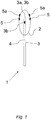
- the device 1 for detection of rhinitis in a human subject has two configurations, or states, wherein Figure 1 depicts a second configuration, or state, of the device.
- the inflatable member 2 is, in its expanded state, arranged to partly surround an expansion member 3, such that the end portion of the expansion member 3 is located inside the inflatable member 2.
- the inflatable member 2 is for example a balloon made of a material such as plastic or rubber. In some instances, the inflatable member is made of latex.
- the expansion member 3 comprises at least one channel 4 for supply of fluid to the inflatable member 2.
- the inflatable member 2 thus comprises a chamber for containing fluid, e.g. gas or liquid, supplied by the expansion member 3.
- the chamber walls are defined by the inner surface of the inflatable member 2.
- the supply of fluid to the inflatable member 2 via the expansion member 3 thus influences the volume and degree of expansion of the inflatable member 2.
- the end portion 3a of the expansion member 3 comprises at least one opening 3b. If the end portion 3a of the expansion member 3 is arranged freely within the inflatable member 2, as for example depicted in Figure 1 , the end portion 3a may comprise more than one opening 3b for supply of fluid to the inflatable member 2.
- the opening(s) 3b can be arranged around a perimeter of the end portion 3a of the expansion member 3 and/or can be arranged in an axial direction at the terminus of end portion 3a of the expansion member 3.
- the opening(s) 3b can be distributed along a longitudinal direction of the portion of the expansion member 3 that is located within the inflatable member 2.
- Examples of an expansion member comprising at least one channel 4 include a pipe, a tubing, a conduit, a cylinder, a tube, etc.
- the expansion member 3 may for instance be made of a plastic, rubber or metal material.
- an inflatable member 2 and an expansion member 3 are anticipated, wherein the inflatable member 2, for example is connected adjacent to the end portion 3a of the expansion member 3 or arranged as a sleeve around the expansion member 3 some distance away from the end portion 3a.
- the parts of the expansion member 3 and inflatable member 2 in contact with the human body typically define a closed system to prevent leakage of fluid to the human body.
- Two pressure sensing members 5 are optionally arranged on the outer surface of the inflatable member 2. This arrangement of pressure sensing members 5 enables accurate measuring of a tissue response pressure as exerted on the surface of the inflatable member 2 when the inflatable member 2 is arranged in its second expanded state within the nasal cavity of a human subject.
- the device 1 may comprise any suitable number of pressure sensing members 5, such as a plurality of pressure sensing members 5 arranged around the circumference of the inflatable member.
- a pressure sensing member 5 that may be arranged on the surface of the inflatable member is a strain gauge. Such a strain gauge may be applied onto the surface, e.g. with glue or by evaporation.
- a pressure sensing member 5 may be integrated within the inflatable member 2.
- the pressure inside the inflatable member 2 is proportional to the pressure exerted by the tissue onto the outer surface of the inflatable member 2 and a pressure sensing member 5 may thus measure the inner pressure of the inflatable member 2.
- An integrated pressure sensing member is a MEMS (Micro-Electro-Mechanical System) device.
- Expansion of the inflatable member 2 may, for example be achieved by increasing the air pressure within the inflatable member 2.
- the expansion member 3 may comprise a pressure generator, e.g. a syringe, a balloon, or a pump, arranged to increase the air pressure within the inflatable member.
- the tissue response pressure may be measured by monitoring the air pressure within the inflatable member 2.
- a pressure sensing member 5 may for example be arranged externally of the inflatable member 2 and in fluid communication with the channel 4.
- a manually operated pumping bulb equipped with a manometer and a closing valve may be used as a pressure generator.
- An exemplary mode of operation is to inflate the inflatable member 2 to a pressure in the range of 100 to 180 mbar by manually squeezing the pumping bulb, closing the valve, and observing the time evolution of the air pressure within the inflatable member 2 as shown on the manometer.
- vibrations may be applied by changing the air volume within the device 1.
- the tissue response pressure as registered by the pressure sensing members 5 can thus give an estimate of the compliance of the tissue surrounding the inflatable member 2. This may give an indication on how the human subject in question would respond to a rhinitis treatment, e.g. a vibrational rhinitis treatment as disclosed in WO 2008/138997 .
- the inflatable member 2 can, for example be provided with separate sensors 5a for either one of temperature, pH, and/or electrical conductivity. Such sensors can be attached to the outside surface of the inflatable member 2 or be integral with the inflatable member 2 as described above with regard to the pressure sensing members 5. By receiving such data in addition to the measured pressure, further characterization of nasal pathology may be possible.
- the device 1 may further comprise a display member 18 configured to display the pressure measured by the pressure sensing member, i.e. the tissue response pressure.
- the display member can be an LCD panel, which can be separate from or part of the control unit 13.
- the display member 18 facilitates monitoring of the tissue response pressure by an operator.
- Such display member 18 may either show a current value of the tissue response pressure only, or may alternatively or also show how the tissue response pressure develops over time.
- the display member 18 is in one embodiment configured to display the pressure measured by the pressure sensing member as a function of time.
- the display member may be digital or analog.
- the display member only shows a current value of the tissue response pressure the operator has to monitor the time development of the signal in order to be able to draw any conclusions regarding the nasal pathology. If the development of the tissue response pressure over time is shown, e.g. on a computer screen or on an XY-plotter, the evaluation of nasal pathology for the operator is facilitated. In both cases however, it is the operator who, based on experience and/or training, draws conclusions regarding the health of the patient.
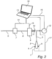
- the system comprises a device 1 having an inflatable member 2 optionally provided with pressure sensing members 5 at the surface.
- the inflatable member 2 is arranged around an expansion member 3 as described above.
- Fluid such as air enters the system via an inlet 6.
- a pressure regulator 7 the fluid is pressurized before being supplied to the device 1 via tubing 8.
- a pressure regulator 7 is a pressure pump.
- the fluid may optionally pass a frequency and amplitude regulator 9.
- a frequency and amplitude regulator 9 is an oscillation pump.
- the frequency and amplitude regulator 9 provides vibrations having a desired frequency and amplitude to the pressurized fluid, which subsequently via tubing 10 and expansion member 3 is supplied to the device 1.
- Tubing 10 is provided with a safety valve 11 for releasing fluid should the pressure within the inflatable member 2 exceed a certain maximum value.
- an external pressure sensor 12 may be provided for controlling the system pressure, and in some instances measure the inner pressure of the inflatable member 2 representing the tissue response pressure.
- the control unit 13 comprises a data collection module (not shown) for obtaining an input signal reflecting a measure of the tissue response pressure exerted on the inflatable member 2 of the device 1 according to the invention.
- the control unit 13 may in some embodiments receive the input signal via line 17 from the pressure sensing members 5 arranged on the device 1.
- the pressure exerted by the nasal tissue onto the inflatable member 2 may be monitored continuously or according to a predetermined schedule.
- the measured pressure may furthermore be stored in the data collection module.
- the system may comprise a display member 18 that is configured to display the pressure measured by the pressure sensing members 5.
- the display member 18 may be integrated with control unit 13, as shown in Figure 2 , or may be arranged as a separate unit.
- the display member 18 may be configured to display the pressure measured by the pressure sensing member as a current value, as a distinct value at a certain time point, or as a function of time.
- the measured pressure is further analyzed by a pressure analyzing module (not shown), optionally arranged within the control unit 13.
- the pressure analyzing module identifies plateaus and decreases in the measured pressure signal, collected for example during a period of from 1 to 10 minutes.
- a rhinitis detection module (not shown) is further provided for comparison of identified plateaus and decreases in the measured pressure to e.g. a predetermined boundary condition or to a reference pressure curve. Rhinitis is hence detected.
- control unit 13 of the system is further connected to the pressure regulator 7 via line 14. Information regarding the applied pressure is thus forwarded from the pressure regulator 7 to the control unit 13 via said line 14.
- the application of pressure may in addition be centrally controlled from control unit 13.
- the frequency and amplitude regulator 9 communicates with the control unit 13 via line 15. Information is forwarded from the optional frequency and amplitude regulator 9 to the control unit via the line 15, and commands are transmitted from the control unit 13 to the frequency and amplitude regulator 9 via said line 15.
- the data collection module, the pressure analyzing module and the rhinitis detection module may be integrated within a common control unit 13 as described above, or can be arranged separately from each other in, e.g. separate control units.
- control unit 13 is a microprocessor comprising suitable peripheral I/O capability executing software, e.g. for analyzing the input signal and for determining how to adjust the pressure and optionally the frequency and the amplitude. It is contemplated that other types of a control unit 13 may be used, such as e.g. a personal computer.
- a tissue response pressure curve is firstly provided.
- the tissue response pressure curve reflects the tissue response pressure of the nasal cavity of a human subject over a period of time.
- the tissue response pressure has thus been measured and collected separately from the current exemplary method.
- an input signal reflecting a tissue response pressure is obtained and a tissue response pressure curve is created by adapting a curve to individual values of the input signal obtained over a period of time, or by sampling said input signal over a period of time.
- the comparison to a reference curve may be easier to perform, especially if the reference curve is formulated in the same way. This can furthermore be an efficient way to remove noise from the signal.
- Use of sampled values eliminates the need for a parameterized representation.
- a reference pressure curve is thereafter provided.
- This reference pressure curve reflects a reference tissue response pressure of the nasal cavity over a reference period of time.
- This reference pressure curve can be obtained according to procedures described herein.
- the tissue response pressure curve is compared to said reference pressure curve in order to assess correspondence between the two.
- the comparison may be of relevance for a subsequent detection step wherein rhinitis is detected by, e.g. determining whether there is correspondence or whether the tissue response pressure curve lies within a predetermined tolerance interval; determining whether at least parts of the tissue response pressure curve exceeds said tolerance interval, and determining whether at least parts of the tissue response pressure curve falls below said tolerance interval.
- rhinitis By applying a static pressure in a balloon inserted into the nasal cavity and monitoring the resulting pressure over time, rhinitis can be detected. Observations from tissue response pressure measurements in the nasal cavities of human patients are accounted for in the following.
- the patients subjected to the measurements have been categorized into three general groups, B), C) and D).
- the first group A) represents healthy patients (i.e. not suffering from rhinitis).
- the second group B represents patients suffering from a subtype of rhinitis.
- This group of patients is commonly referred to as blockers.
- Blockers experience a stuffy nose, sometimes in combination with sneezes.
- These patients have typically been treated with pharmaceuticals (e.g. cortisone) with a success rate below 50% in the non-allergic cases.
- An alternative treatment option is invasive tissue destructive surgery. This group constitutes about 80% of the rhinitis patients.
- the third group C) also represents patients suffering from a subtype of rhinitis, and this group is commonly referred to as sneezers. Sneezers, as the name implies, sneeze a lot. Sneezing is often accompanied by increased secretion in the nose. This group constitutes about 10% of the rhinitis patients.
- the fourth group D also represents patients suffering from a subtype of rhinitis. This group is commonly denoted runners. Typical symptoms include a lot of secretion in the nose. The runners represent the remaining 10% of the rhinitis patients and are the most problematic to treat. There are most likely several pathologies contributing to this type of syndrome, for instance connected to aging. These patients are often therapy resistant.
- the inflatable member used was a balloon which in an expanded state had a diameter of approximately 1.5 cm and a length of 5 cm.
- the balloon was connected with a tubing having a length of approximately 15 cm.
- the tubing and the balloon were connected to each other such that one end of the tubing resided within the balloon, having a length of maximally 4 cm to simplify introduction into the nasal cavity.
- the tubing supplied air to the balloon for expanding the same.
- the other end of the tubing was connected via a three-way cock to a graduated syringe (20 ml) as well as to another tubing, which was connected to a closed air system.
- the closed air system was connected to a flexible membrane, which during some pressure measurements was oscillated with a variable frequency in the interval 10-100 Hz by means of a motor.
- the air pressure could be varied in a controlled manner within a pressure interval of 5-180 mbar.
- the amplitude of the oscillating membrane could be varied in a controlled manner (in arbitrary but reproducible units).
- the balloon Prior to use, the balloon was provided with a hygienic protective cover, consisting of a finger from a disposable glove. The hygienic protective cover was dipped in a paraffin solution prior to each introduction into a nasal cavity.
- the initial pressure decrease was slower compared to the healthy reference, see Figure 4 b) .
- the relatively small decreases and long plateaus are hypothesized to be due to sphincters being stuck and unable to open in the way they do in healthy subjects.
- tissue response pressure dropped comparatively fast with relatively short plateau periods between the pressure drops.
- the reason for this might be that the sphincters could only withstand the applied pressure for a short period of time.
- the rhinitis patients After being subjected to vibration administration, essentially as described in WO 2008/138997 , the rhinitis patients displayed the same type of tissue response pressure curves as those of group A). It is believed that when the initially strong reaction of the rhinitis patients diminished, the patients were relieved of his/her symptoms.
Landscapes
- Health & Medical Sciences (AREA)
- Life Sciences & Earth Sciences (AREA)
- Surgery (AREA)
- Engineering & Computer Science (AREA)
- Veterinary Medicine (AREA)
- Biomedical Technology (AREA)
- Heart & Thoracic Surgery (AREA)
- Medical Informatics (AREA)
- Molecular Biology (AREA)
- Animal Behavior & Ethology (AREA)
- General Health & Medical Sciences (AREA)
- Public Health (AREA)
- Physics & Mathematics (AREA)
- Pathology (AREA)
- Biophysics (AREA)
- Nuclear Medicine, Radiotherapy & Molecular Imaging (AREA)
- Dentistry (AREA)
- Oral & Maxillofacial Surgery (AREA)
- Reproductive Health (AREA)
- Vascular Medicine (AREA)
- Hematology (AREA)
- Pulmonology (AREA)
- Otolaryngology (AREA)
- Radiology & Medical Imaging (AREA)
- Optics & Photonics (AREA)
- Artificial Intelligence (AREA)
- Computer Vision & Pattern Recognition (AREA)
- Physiology (AREA)
- Psychiatry (AREA)
- Signal Processing (AREA)
- Measuring And Recording Apparatus For Diagnosis (AREA)
Claims (15)
- System zum Detektieren von Rhinitis, umfassend:eine Vorrichtung (1) zum Detektieren von Rhinitis bei einem menschlichen Individuum, umfassend:ein aufblasbares Element (2), das in einem ersten Zustand so konfiguriert ist, dass es in die Nasenhöhle des menschlichen Individuums einführbar ist;ein Ausdehnungselement (3), das konfiguriert ist, das aufblasbare Element in einen ausgedehnten zweiten Zustand innerhalb der Nasenhöhle derart auszudehnen, dass das aufblasbare Element (2) gegen das Gewebe der Nasenhöhle stößt;wobei das System ferner ein Druckerfassungselement (5) umfasst, das konfiguriert ist, um einen Druck zu messen, der in dem zweiten Zustand durch das Gewebe der Nasenhöhle auf das aufblasbare Element (2) ausgeübt wird; unddas System ferner umfasst:ein Datensammelmodul, das konfiguriert ist, um ein Eingangssignal zu erhalten, das einen Gewebereaktionsdruck der Nasenhöhle des menschlichen Individuums widerspiegelt, wobei der Gewebereaktionsdruck dem Druck entspricht, der durch Gewebe der Nasenhöhle auf das aufblasbare Element (2) in dem ausgedehnten zweiten Zustand ausgeübt wird;das gekennzeichnet ist durchein Druckanalysemodul, das konfiguriert ist, das Eingangssignal zu analysieren, um Plateaus und Abnahmen des Signals über eine Zeitspanne hinweg zu identifizieren, undein Rhinitisdetektionsmodul, das konfiguriert ist, um Rhinitis durch Vergleichen der Plateaus und der Abnahmen des Signals über die Zeit mit mindestens einer vorbestimmten Randbedingung zu detektieren.
- System nach Anspruch 1, wobei das Druckanalysemodul konfiguriert ist, die Plateaus und die Abnahmen des Signals durch mindestens eine Kurveneigenschaft zu charakterisieren, die ausgewählt ist aus Amplitude, Änderungsrate und Häufigkeit.
- System nach Anspruch 2, wobei das Rhinitisdetektionsmodul konfiguriert ist, um einen ersten und einen zweiten Subtyp von Rhinitis durch Auffinden von Abschnitten von mindestens einer der Kurveneigenschaften zu detektieren, die individuelle Werte oberhalb von einem vorbestimmten Schwellenwertmax für diese bestimmte Kurveneigenschaft aufweisen, um einen ersten Subtyp von Rhinitis zu detektieren, und durch Auffinden von Abschnitten von mindestens einer der Kurveneigenschaften, die individuelle Werte unter einem vorbestimmten Schwellenwertmin für diese bestimmte Kurveneigenschaft aufweisen, um einen zweiten Subtyp der Rhinitis zu detektieren.
- System gemäß einem der Ansprüche 1 bis 3, wobei das Druckanalysemodul konfiguriert ist, um Spitzen zu detektieren, die Niesen im Eingangssignal entsprechen.
- System gemäß einem der Ansprüche 1 bis 4, wobei das aufblasbare Element (2) in dem zweiten Zustand so konfiguriert ist, dass es gegen das Gewebe der Nasenhöhle bei einem Druck zwischen 100 und 180 mbar stößt.
- System nach einem der vorhergehenden Ansprüche, wobei die Vorrichtung zwei oder mehr Druckerfassungselemente (5) aufweist, die auf der Oberfläche des aufblasbaren Elements (2) angeordnet sind.
- System gemäß Anspruch 6, wobei die Druckerfassungselemente (5) Dehnungsmesser sind.
- System gemäß Anspruch einem der vorhergehenden Ansprüche, wobei das Druckerfassungselement (5) in dem aufblasbaren Element (2) integriert ist.
- System nach einem der vorhergehenden Ansprüche, wobei das aufblasbare Element (2) mit einem schwingungserzeugenden Element verbindbar ist, das konfiguriert ist, um das aufblasbare Element (2) derart zum Vibrieren zu bringen, dass Vibrationen auf das Gewebe der Nasenhöhle übertragen werden.
- System nach einem der vorhergehenden Ansprüche , wobei die Vorrichtung (1) ferner ein Anzeigeelement umfasst, das konfiguriert ist, den durch das Druckerfassungselement gemessenen Druck anzuzeigen.
- System nach einem der vorhergehenden Ansprüche, wobei die Vorrichtung (1) ferner andere Arten von Sensorelementen umfasst, wie etwa Sensoren (5a) zum Messen der Temperatur, des pH-Wertes und / oder der elektrischen Leitfähigkeit.
- System nach einem der Ansprüche 9 bis 11, ferner umfassend ein Nachgiebigkeitsbestimmungsmodul, das konfiguriert ist, um die Nachgiebigkeit des Gewebes auf die übertragenen Schwingungen zu bestimmen.
- Verfahren zum Detektieren von Rhinitis, zum Beurteilen der Wirksamkeit einer vorher durchgeführten Rhinitis-Behandlung oder zum Prognostizieren der Wirksamkeit einer Rhinitis-Behandlung, wobei das Verfahren die Schritte umfasst:Einführen eines aufblasbaren Elements (2) in die Nasenhöhle eines menschlichen Subjekts;Ausdehnen des aufblasbaren Elements (2) innerhalb der Nasenhöhle derart, dass das aufblasbare Element (2) gegen ein Gewebe der Nasenhöhle stößt;wobei ein Druck, der auf das aufblasbare Element (2) durch das Gewebe der Nasenhöhle ausgeübt wird, über einen Zeitraum gemessen wird, um eine gemessene Druckkurve zu erzeugen; unddie gemessene Druckkurve analysiert wird, um Rhinitis zu detektieren, die Wirksamkeit einer Rhinitis-Behandlung zu prognostizieren oder die Wirksamkeit der vorhergehenden Rhinitis-Behandlung zu beurteilen,wobei der Schritt des Analysierens ferner das Identifizieren von Plateaus und Abnahmen in der gemessenen Druckkurve und das Vergleichen des Plateaus und Abnahmen mit mindestens einer vorbestimmten Randbedingung umfasst.
- Verfahren nach Anspruch 13, ferner umfassend das Vergleichen der gemessenen Druckkurve mit einer Referenzdruckkurve, wobei die Referenzdruckkurve ausgewählt ist aus
einer vorher erhaltenen Gewebereaktionsdruckkurve;
einem Mittelwert von mindestens zwei vorher erhaltenen Gewebereaktionsdruckkurven;
einer Anpassung eines Modells an mindestens eine gemessene Gewebereaktionsdruckkurve, und
einer theoretisch berechneten Referenzdruckkurve. - Verfahren nach Anspruch 14, wobei das Vergleichen mindestens eines der Folgenden umfasst
Bestimmen, dass die Gewebereaktionsdruckkurve der Referenzdruckkurve entspricht oder innerhalb eines vorbestimmten Toleranzintervalls liegt;
Bestimmen, dass mindestens Teile der Gewebereaktionsdruckkurve das Toleranzintervall überschreiten, und
Bestimmen, dass mindestens Teile der Gewebereaktionsdruckkurve das Toleranzintervall unterschreiten.
Priority Applications (1)
| Application Number | Priority Date | Filing Date | Title |
|---|---|---|---|
| EP12808352.4A EP2790569B1 (de) | 2011-12-16 | 2012-12-14 | Druckmesssystem und -verfahren |
Applications Claiming Priority (4)
| Application Number | Priority Date | Filing Date | Title |
|---|---|---|---|
| US201161576804P | 2011-12-16 | 2011-12-16 | |
| EP11194062 | 2011-12-16 | ||
| EP12808352.4A EP2790569B1 (de) | 2011-12-16 | 2012-12-14 | Druckmesssystem und -verfahren |
| PCT/EP2012/075638 WO2013087883A1 (en) | 2011-12-16 | 2012-12-14 | Pressure sensing system and method |
Publications (2)
| Publication Number | Publication Date |
|---|---|
| EP2790569A1 EP2790569A1 (de) | 2014-10-22 |
| EP2790569B1 true EP2790569B1 (de) | 2018-01-10 |
Family
ID=48610843
Family Applications (1)
| Application Number | Title | Priority Date | Filing Date |
|---|---|---|---|
| EP12808352.4A Active EP2790569B1 (de) | 2011-12-16 | 2012-12-14 | Druckmesssystem und -verfahren |
Country Status (5)
| Country | Link |
|---|---|
| US (2) | US9198618B2 (de) |
| EP (1) | EP2790569B1 (de) |
| JP (1) | JP6134734B2 (de) |
| CN (1) | CN104144635B (de) |
| WO (2) | WO2013087883A1 (de) |
Families Citing this family (9)
| Publication number | Priority date | Publication date | Assignee | Title |
|---|---|---|---|---|
| CN103877656B (zh) * | 2014-04-09 | 2016-02-17 | 济南市第四人民医院 | 一种喉罩、喉罩的制作方法以及喉罩的插管方法 |
| GB201415649D0 (en) * | 2014-09-04 | 2014-10-22 | Univ Heriot Watt | A membrane sensor for dynamic instrumented palpatation of soft materials |
| WO2016185322A1 (en) * | 2015-05-20 | 2016-11-24 | Thd S.P.A. | An apparatus for manometric measurements and a method of measurement thereof |
| CN106264497A (zh) * | 2015-06-10 | 2017-01-04 | 武汉左点科技有限公司 | 基于智能化鼻炎治疗仪的健康信息管理系统及方法 |
| US20180064392A1 (en) * | 2016-09-07 | 2018-03-08 | Empire Technology Development Llc | Detection of foot edema through in-shoe pressure sensors |
| CN107782523B (zh) * | 2017-10-31 | 2019-05-24 | 中国空气动力研究与发展中心高速空气动力研究所 | 一种空腔模态噪声驻波分解方法 |
| CN108187238A (zh) * | 2018-02-08 | 2018-06-22 | 东莞艮顺电子科技有限公司 | 一种用于治疗鼻炎的光鼻器 |
| KR102056541B1 (ko) | 2018-07-06 | 2019-12-16 | 임화목 | 비염 또는 중이염 예방 및 치료를 위한 광 파장 발생기 |
| CN109497946B (zh) * | 2018-11-14 | 2021-05-04 | 山东师范大学 | 一种鼻炎分型判定系统 |
Family Cites Families (89)
| Publication number | Priority date | Publication date | Assignee | Title |
|---|---|---|---|---|
| US901376A (en) | 1907-09-06 | 1908-10-20 | Harvey H Roberts | Massage and vibratory dilator. |
| US912205A (en) | 1908-06-09 | 1909-02-09 | Solox Chemical Company | Apparatus for applying internal massage. |
| US961034A (en) | 1909-09-02 | 1910-06-07 | Siebert Welch Company | Massage apparatus. |
| FR592104A (fr) | 1924-03-20 | 1925-07-28 | Préparateur dilatateur périnéal | |
| US1735519A (en) | 1926-07-17 | 1929-11-12 | Arlyn T Vance | Physician's dilator |
| US1764838A (en) | 1928-11-03 | 1930-06-17 | Newton H Horne | Hydraulic pulsator |
| GB385992A (en) | 1931-07-04 | 1933-01-04 | Georges Klass | A device to relieve and soothe nervous headache and insomnia |
| US2052321A (en) | 1934-07-25 | 1936-08-25 | Smart Harry Vincent | Treatment of sinuses |
| US2101273A (en) | 1935-01-09 | 1937-12-07 | Wallace D Smith | Massage instrument for treating the prostate gland |
| FR838034A (fr) | 1938-05-16 | 1939-02-24 | Perfectionnements apportés aux dispositifs pour le traitement du grand sympathique à l'aide de touches nasales | |
| FR920885A (fr) | 1945-10-22 | 1947-04-21 | Appareil éducateur et contrôleur de muscles organiques | |
| CH329193A (de) | 1954-07-24 | 1958-04-15 | Maurice Dr Med Fuchs | Massagevorrichtung |
| US3496932A (en) | 1967-12-22 | 1970-02-24 | Gen Motors Corp | Method and apparatus for substernal cardiac massage |
| US3612211A (en) | 1969-07-02 | 1971-10-12 | William T Clark | Method of producing locally occurring infrasound |
| US3848607A (en) | 1971-10-29 | 1974-11-19 | M Clair | Therapeutic apparatus |
| US4462411A (en) | 1981-01-07 | 1984-07-31 | The University Of Melbourne | Evoked response audiometer |
| SU1148614A1 (ru) | 1982-03-25 | 1985-04-07 | Пензенский государственный институт усовершенствования врачей | Способ лечени хронического атрофического ринита |
| US4911149A (en) | 1984-06-18 | 1990-03-27 | Urological Instruments Research, Inc. | Vibratory treatment method and apparatus |
| SE8404375D0 (sv) | 1984-08-31 | 1984-08-31 | Jerzy Antowski | Behandlingsapparat for menieer-sjukdom |
| SU1560205A1 (ru) | 1987-04-27 | 1990-04-30 | Пензенский государственный институт усовершенствования врачей | Устройство дл внутриносового вибромассажа |
| US5139510A (en) | 1991-02-22 | 1992-08-18 | Xomed-Treace Inc. | Nasal packing device |
| RU2099039C1 (ru) | 1992-03-13 | 1997-12-20 | Зеленкин Евгений Михайлович | Способ лечения нейровегетативной формы вазомоторного ринита |
| DE69417465T2 (de) | 1993-02-05 | 1999-07-22 | Joe W And Dorothy Dorsett Brow | Ultraschallballonkatheter für Angioplastik |
| US5545133A (en) * | 1994-09-16 | 1996-08-13 | Scimed Life Systems, Inc. | Balloon catheter with improved pressure source |
| DE29508077U1 (de) | 1995-05-16 | 1995-08-10 | Wilden Lutz Dr Med | Mundpflegegerät |
| WO1996039218A1 (en) | 1995-06-06 | 1996-12-12 | Hogle Gregory A | Inflatable nasal packing device |
| US5903516A (en) | 1996-05-08 | 1999-05-11 | Mayo Foundation For Medical Education And Research | Acoustic force generator for detection, imaging and information transmission using the beat signal of multiple intersecting sonic beams |
| CA2255622A1 (en) | 1996-06-18 | 1997-12-24 | Robert H. Niemeyer | Intrathoracic cardiac compression |
| US5846218A (en) | 1996-09-05 | 1998-12-08 | Pharmasonics, Inc. | Balloon catheters having ultrasonically driven interface surfaces and methods for their use |
| US5682881A (en) | 1996-10-21 | 1997-11-04 | Winthrop; Neil | Nasal CPAP/Cannula and securement apparatus |
| US6159170A (en) | 1997-03-13 | 2000-12-12 | Borodulin; German | Universal mechanical dilator combined with massaging action |
| US6647296B2 (en) | 1997-10-27 | 2003-11-11 | Neuropace, Inc. | Implantable apparatus for treating neurological disorders |
| US20040230252A1 (en) | 1998-10-21 | 2004-11-18 | Saul Kullok | Method and apparatus for affecting the autonomic nervous system |
| US6748275B2 (en) | 1999-05-05 | 2004-06-08 | Respironics, Inc. | Vestibular stimulation system and method |
| JP2001017500A (ja) | 1999-07-07 | 2001-01-23 | Shintou Something:Kk | 鼻炎治療具 |
| JP2001037883A (ja) | 1999-07-27 | 2001-02-13 | Olympus Optical Co Ltd | ダイレータ |
| WO2001035846A1 (en) | 1999-11-16 | 2001-05-25 | Ganz Robert A | System and method of treating abnormal tissue in the human esophagus |
| US20060095032A1 (en) | 1999-11-16 | 2006-05-04 | Jerome Jackson | Methods and systems for determining physiologic characteristics for treatment of the esophagus |
| CA2395146A1 (en) | 1999-12-13 | 2001-06-14 | Theracardia, Inc. | Minimally-invasive direct massage apparatus and method |
| AU2001275921A1 (en) | 2000-07-14 | 2002-01-30 | Hill-Rom Services, Inc. | Pulmonary therapy apparatus |
| ZA200306564B (en) | 2001-02-26 | 2004-10-15 | Optinose As | Nasal devices. |
| US7011629B2 (en) * | 2001-05-14 | 2006-03-14 | American Doctors On-Line, Inc. | System and method for delivering medical examination, treatment and assistance over a network |
| RU2199303C1 (ru) | 2001-06-19 | 2003-02-27 | Научно-клинический центр оториноларингологии | Способ вибротерапии нейровегетативной формы вазомоторного ринита |
| AU2002324574A1 (en) | 2001-07-27 | 2003-02-17 | Wit Ip Corporation | Methods for treating prostatitis |
| US20030087734A1 (en) | 2001-11-02 | 2003-05-08 | Kring Robert S. | Vaginal-pelvic muscle exerciser and birthing trainer |
| US8317816B2 (en) | 2002-09-30 | 2012-11-27 | Acclarent, Inc. | Balloon catheters and methods for treating paranasal sinuses |
| CA2449093C (en) | 2002-11-13 | 2009-01-20 | Dymedso Inc. | Acoustic therapeutic device and method for treating cystic fibrosis and other respiratory pathologies |
| US7077812B2 (en) * | 2002-11-22 | 2006-07-18 | The Board Regents Of The University System | Apparatus and method for palpographic characterization of vulnerable plaque and other biological tissue |
| JP3966468B2 (ja) * | 2003-02-12 | 2007-08-29 | 学校法人日本大学 | 生体組織の弾力特性測定装置 |
| US7108706B2 (en) | 2003-05-28 | 2006-09-19 | Rose Biomedical Development Corporation | Inflatable nasal packing device with two non-elastic, flexible bags oversized relative to nasal cavities |
| US7149574B2 (en) | 2003-06-09 | 2006-12-12 | Palo Alto Investors | Treatment of conditions through electrical modulation of the autonomic nervous system |
| US7066180B2 (en) | 2003-07-09 | 2006-06-27 | Airmatrix Technologies, Inc. | Method and system for measuring airflow of nares |
| CA2439667A1 (en) | 2003-09-04 | 2005-03-04 | Andrew Kenneth Hoffmann | Low frequency vibration assisted blood perfusion system and apparatus |
| US7419497B2 (en) * | 2004-04-21 | 2008-09-02 | Acclarent, Inc. | Methods for treating ethmoid disease |
| US9101384B2 (en) * | 2004-04-21 | 2015-08-11 | Acclarent, Inc. | Devices, systems and methods for diagnosing and treating sinusitis and other disorders of the ears, Nose and/or throat |
| US20060063973A1 (en) * | 2004-04-21 | 2006-03-23 | Acclarent, Inc. | Methods and apparatus for treating disorders of the ear, nose and throat |
| US20050267388A1 (en) | 2004-05-26 | 2005-12-01 | Hanna Joseph P | Method and apparatus for relief of headache |
| CA2574013A1 (en) * | 2004-07-14 | 2006-01-19 | By-Pass, Inc. | Material delivery system |
| GB0421215D0 (en) | 2004-09-23 | 2004-10-27 | Procyon Instr Ltd | Pupillometers |
| US20060095065A1 (en) * | 2004-09-24 | 2006-05-04 | Tetsuaki Tanimura | Fluid occluding devices and methods |
| US7510537B2 (en) | 2004-11-02 | 2009-03-31 | Ethan Frederic Imboden | Personal vibrator with replaceable motor having the appearance of a battery |
| US7364573B2 (en) | 2004-11-30 | 2008-04-29 | Anthony Garabet | Method and apparatus for pressurizing a body cavity for diagnostic and rehabilitative purposes |
| WO2006114783A2 (en) * | 2005-04-28 | 2006-11-02 | Bypass, Inc. | Material delivery system |
| CN101208127A (zh) | 2005-04-28 | 2008-06-25 | 旁路公司 | 材料输送系统 |
| ES2379383T3 (es) | 2005-06-02 | 2012-04-25 | Ads&B Investment Fund L.P. | Un dispositivo vibratorio para tratar síntomas de congestión nasal y de sinusitis |
| US8758294B2 (en) * | 2005-12-27 | 2014-06-24 | Acist Medical Systems, Inc. | Balloon inflation device |
| US20070269385A1 (en) * | 2006-05-18 | 2007-11-22 | Mercator Medsystems, Inc | Devices, methods, and systems for delivering therapeutic agents for the treatment of sinusitis, rhinitis, and other disorders |
| US20100004709A1 (en) | 2006-10-26 | 2010-01-07 | Hans Alois Mische | Physiologic stimulation for stroke treatment |
| US20080172033A1 (en) * | 2007-01-16 | 2008-07-17 | Entellus Medical, Inc. | Apparatus and method for treatment of sinusitis |
| US20090005713A1 (en) | 2007-02-12 | 2009-01-01 | Podrazhansky Yury M | Method and Device for Using Vibroacoustical Stimulation to Treat Target Tissue Areas of Living Organisms |
| JP4572214B2 (ja) | 2007-05-09 | 2010-11-04 | 株式会社アクション・リサーチ | 振動呈示装置 |
| SE531172C2 (sv) * | 2007-05-16 | 2009-01-13 | Rhinomed Ab | Vibrationsanordning avsedd att användas i kroppskaviteter, företrädesvis i näshålan |
| WO2008152639A2 (en) * | 2007-06-12 | 2008-12-18 | Bypass, Inc. | Pressure pulse actuating device for delivery systems |
| US20090076439A1 (en) * | 2007-09-14 | 2009-03-19 | Dollar Michael L | Inflation System for Balloon Catheter |
| US7722544B2 (en) * | 2007-10-17 | 2010-05-25 | Datascope Investment Corp. | Calibration of in vivo blood pressure sensors |
| US20100274188A1 (en) * | 2007-12-20 | 2010-10-28 | Acclarent, Inc. | Method and System for Treating Target Tissue Within the Eustachian Tube |
| US8483831B1 (en) * | 2008-02-15 | 2013-07-09 | Holaira, Inc. | System and method for bronchial dilation |
| WO2009136931A1 (en) | 2008-05-08 | 2009-11-12 | Lotus Magnus, Llc. | Systems, devices, and methods for treating restless leg syndrome and periodic limb movement disorder |
| US8777870B2 (en) * | 2008-05-15 | 2014-07-15 | Michel H. Malek | Functional discography catheter |
| WO2010033055A1 (en) | 2008-09-17 | 2010-03-25 | Handmedic Hb | A system for applying controlled selective vibration stimuli to the hand |
| US7951111B2 (en) * | 2008-10-10 | 2011-05-31 | Intervalve, Inc. | Valvuloplasty catheter and methods |
| US8226601B2 (en) * | 2008-11-12 | 2012-07-24 | Sanovas, Inc. | Resector balloon system |
| CA2753870C (en) | 2009-03-06 | 2017-06-13 | Neuralieve | Method and apparatus to record and analyze tms treatments and results |
| US20100286576A1 (en) | 2009-05-06 | 2010-11-11 | Bwt Property, Inc. | Photo Therapy and Massage Apparatus for Relieving Pain in Body Cavities |
| CN102573617B (zh) | 2009-07-29 | 2014-09-10 | 梅奥医学教育和研究基金会 | 用于评估体腔压力的系统、设备和方法 |
| US20110190668A1 (en) | 2010-02-03 | 2011-08-04 | Mishelevich David J | Ultrasound neuromodulation of the sphenopalatine ganglion |
| US20110270138A1 (en) | 2010-05-02 | 2011-11-03 | Mishelevich David J | Ultrasound macro-pulse and micro-pulse shapes for neuromodulation |
| KR101019957B1 (ko) | 2010-09-08 | 2011-03-09 | 박충식 | 휴대용 비염치료기 |
| US9238126B2 (en) * | 2011-04-08 | 2016-01-19 | Sanovas Inc. | Biofeedback controlled deformation of sinus ostia |
-
2012
- 2012-12-14 EP EP12808352.4A patent/EP2790569B1/de active Active
- 2012-12-14 CN CN201280069146.0A patent/CN104144635B/zh active Active
- 2012-12-14 WO PCT/EP2012/075638 patent/WO2013087883A1/en active Application Filing
- 2012-12-14 JP JP2014546547A patent/JP6134734B2/ja active Active
- 2012-12-14 WO PCT/EP2012/075624 patent/WO2013087877A1/en active Application Filing
- 2012-12-14 US US13/714,636 patent/US9198618B2/en active Active
-
2015
- 2015-10-22 US US14/920,614 patent/US9451889B2/en active Active
Also Published As
| Publication number | Publication date |
|---|---|
| EP2790569A1 (de) | 2014-10-22 |
| US20160038046A1 (en) | 2016-02-11 |
| CN104144635B (zh) | 2017-03-08 |
| JP2015500112A (ja) | 2015-01-05 |
| WO2013087883A1 (en) | 2013-06-20 |
| WO2013087877A1 (en) | 2013-06-20 |
| US9451889B2 (en) | 2016-09-27 |
| US20130158426A1 (en) | 2013-06-20 |
| CN104144635A (zh) | 2014-11-12 |
| US9198618B2 (en) | 2015-12-01 |
| JP6134734B2 (ja) | 2017-05-24 |
Similar Documents
| Publication | Publication Date | Title |
|---|---|---|
| US9451889B2 (en) | Pressure sensing system and method | |
| US9358038B2 (en) | Spinal canal access and probe positioning, devices and methods | |
| US6338719B1 (en) | Method and system for detecting vascular conditions using an occlusive arm cuff plethysmograph | |
| US10506965B2 (en) | Bladder health monitoring system and related methods and devices | |
| EP2818106B1 (de) | Gerät zur Bestimmung eines Atemzustandes | |
| CN108135506B (zh) | 用于评估哺乳动物中的内皮功能的方法和装置 | |
| CN103501693B (zh) | 采用血压袖带的内皮功能评价 | |
| US7955278B1 (en) | Aspiration methods and devices for assessment of viscoelastic properties of soft tissues | |
| JP3882084B2 (ja) | 動脈硬化解析システム、動脈硬化解析方法及び動脈硬化解析プログラム | |
| JP2015167685A (ja) | 血管内皮機能検査装置 | |
| JP7170646B2 (ja) | 術後出血を早期検出するためのシステム | |
| US11166676B2 (en) | Real-time kidney monitoring medical device | |
| US9730629B2 (en) | Vaginal biomechanics analyzer | |
| KR101069489B1 (ko) | 말초 혈관 및 혈류상태 진단장치 및 방법 | |
| US20070055162A1 (en) | Method for obtaining the valid systolic blood pressure of patients with hardened arteries | |
| US9730630B2 (en) | Vaginal biomechanics analyzer | |
| KR20080043545A (ko) | 휴대용 맥진기 및 그 맥진방법 | |
| JP7158473B2 (ja) | ユーザの視野の低下の進行をモニタするための装置および同装置の作動方法 | |
| EP2900122B1 (de) | Vorrichtung zur messung des brachialisblutdrucks bei einer person | |
| KR100904751B1 (ko) | 요실금 진단 시스템 | |
| US20060116630A1 (en) | Method & apparatus for pressurizing a body cavity for diagnostic and rehabilitative purposes | |
| CN103705205B (zh) | 下睑缘压力检测仪 | |
| US20110034788A1 (en) | Methods and apparatus for using multiple sensors to measure differential blood transport time in a patient |
Legal Events
| Date | Code | Title | Description |
|---|---|---|---|
| PUAI | Public reference made under article 153(3) epc to a published international application that has entered the european phase |
Free format text: ORIGINAL CODE: 0009012 |
|
| 17P | Request for examination filed |
Effective date: 20140702 |
|
| AK | Designated contracting states |
Kind code of ref document: A1 Designated state(s): AL AT BE BG CH CY CZ DE DK EE ES FI FR GB GR HR HU IE IS IT LI LT LU LV MC MK MT NL NO PL PT RO RS SE SI SK SM TR |
|
| DAX | Request for extension of the european patent (deleted) | ||
| 17Q | First examination report despatched |
Effective date: 20150831 |
|
| GRAP | Despatch of communication of intention to grant a patent |
Free format text: ORIGINAL CODE: EPIDOSNIGR1 |
|
| STAA | Information on the status of an ep patent application or granted ep patent |
Free format text: STATUS: GRANT OF PATENT IS INTENDED |
|
| INTG | Intention to grant announced |
Effective date: 20170725 |
|
| GRAS | Grant fee paid |
Free format text: ORIGINAL CODE: EPIDOSNIGR3 |
|
| GRAA | (expected) grant |
Free format text: ORIGINAL CODE: 0009210 |
|
| STAA | Information on the status of an ep patent application or granted ep patent |
Free format text: STATUS: THE PATENT HAS BEEN GRANTED |
|
| RAP1 | Party data changed (applicant data changed or rights of an application transferred) |
Owner name: CHORDATE MEDICAL AB |
|
| AK | Designated contracting states |
Kind code of ref document: B1 Designated state(s): AL AT BE BG CH CY CZ DE DK EE ES FI FR GB GR HR HU IE IS IT LI LT LU LV MC MK MT NL NO PL PT RO RS SE SI SK SM TR |
|
| REG | Reference to a national code |
Ref country code: CH Ref legal event code: EP Ref country code: AT Ref legal event code: REF Ref document number: 961501 Country of ref document: AT Kind code of ref document: T Effective date: 20180115 |
|
| REG | Reference to a national code |
Ref country code: IE Ref legal event code: FG4D |
|
| REG | Reference to a national code |
Ref country code: DE Ref legal event code: R096 Ref document number: 602012041996 Country of ref document: DE |
|
| REG | Reference to a national code |
Ref country code: NL Ref legal event code: MP Effective date: 20180110 |
|
| REG | Reference to a national code |
Ref country code: AT Ref legal event code: MK05 Ref document number: 961501 Country of ref document: AT Kind code of ref document: T Effective date: 20180110 |
|
| PG25 | Lapsed in a contracting state [announced via postgrant information from national office to epo] |
Ref country code: NL Free format text: LAPSE BECAUSE OF FAILURE TO SUBMIT A TRANSLATION OF THE DESCRIPTION OR TO PAY THE FEE WITHIN THE PRESCRIBED TIME-LIMIT Effective date: 20180110 |
|
| PG25 | Lapsed in a contracting state [announced via postgrant information from national office to epo] |
Ref country code: NO Free format text: LAPSE BECAUSE OF FAILURE TO SUBMIT A TRANSLATION OF THE DESCRIPTION OR TO PAY THE FEE WITHIN THE PRESCRIBED TIME-LIMIT Effective date: 20180410 Ref country code: FI Free format text: LAPSE BECAUSE OF FAILURE TO SUBMIT A TRANSLATION OF THE DESCRIPTION OR TO PAY THE FEE WITHIN THE PRESCRIBED TIME-LIMIT Effective date: 20180110 Ref country code: LT Free format text: LAPSE BECAUSE OF FAILURE TO SUBMIT A TRANSLATION OF THE DESCRIPTION OR TO PAY THE FEE WITHIN THE PRESCRIBED TIME-LIMIT Effective date: 20180110 Ref country code: HR Free format text: LAPSE BECAUSE OF FAILURE TO SUBMIT A TRANSLATION OF THE DESCRIPTION OR TO PAY THE FEE WITHIN THE PRESCRIBED TIME-LIMIT Effective date: 20180110 Ref country code: ES Free format text: LAPSE BECAUSE OF FAILURE TO SUBMIT A TRANSLATION OF THE DESCRIPTION OR TO PAY THE FEE WITHIN THE PRESCRIBED TIME-LIMIT Effective date: 20180110 Ref country code: CY Free format text: LAPSE BECAUSE OF FAILURE TO SUBMIT A TRANSLATION OF THE DESCRIPTION OR TO PAY THE FEE WITHIN THE PRESCRIBED TIME-LIMIT Effective date: 20180110 |
|
| PG25 | Lapsed in a contracting state [announced via postgrant information from national office to epo] |
Ref country code: GR Free format text: LAPSE BECAUSE OF FAILURE TO SUBMIT A TRANSLATION OF THE DESCRIPTION OR TO PAY THE FEE WITHIN THE PRESCRIBED TIME-LIMIT Effective date: 20180411 Ref country code: BG Free format text: LAPSE BECAUSE OF FAILURE TO SUBMIT A TRANSLATION OF THE DESCRIPTION OR TO PAY THE FEE WITHIN THE PRESCRIBED TIME-LIMIT Effective date: 20180410 Ref country code: IS Free format text: LAPSE BECAUSE OF FAILURE TO SUBMIT A TRANSLATION OF THE DESCRIPTION OR TO PAY THE FEE WITHIN THE PRESCRIBED TIME-LIMIT Effective date: 20180510 Ref country code: PL Free format text: LAPSE BECAUSE OF FAILURE TO SUBMIT A TRANSLATION OF THE DESCRIPTION OR TO PAY THE FEE WITHIN THE PRESCRIBED TIME-LIMIT Effective date: 20180110 Ref country code: LV Free format text: LAPSE BECAUSE OF FAILURE TO SUBMIT A TRANSLATION OF THE DESCRIPTION OR TO PAY THE FEE WITHIN THE PRESCRIBED TIME-LIMIT Effective date: 20180110 Ref country code: SE Free format text: LAPSE BECAUSE OF FAILURE TO SUBMIT A TRANSLATION OF THE DESCRIPTION OR TO PAY THE FEE WITHIN THE PRESCRIBED TIME-LIMIT Effective date: 20180110 Ref country code: RS Free format text: LAPSE BECAUSE OF FAILURE TO SUBMIT A TRANSLATION OF THE DESCRIPTION OR TO PAY THE FEE WITHIN THE PRESCRIBED TIME-LIMIT Effective date: 20180110 Ref country code: AT Free format text: LAPSE BECAUSE OF FAILURE TO SUBMIT A TRANSLATION OF THE DESCRIPTION OR TO PAY THE FEE WITHIN THE PRESCRIBED TIME-LIMIT Effective date: 20180110 |
|
| REG | Reference to a national code |
Ref country code: DE Ref legal event code: R097 Ref document number: 602012041996 Country of ref document: DE |
|
| PG25 | Lapsed in a contracting state [announced via postgrant information from national office to epo] |
Ref country code: EE Free format text: LAPSE BECAUSE OF FAILURE TO SUBMIT A TRANSLATION OF THE DESCRIPTION OR TO PAY THE FEE WITHIN THE PRESCRIBED TIME-LIMIT Effective date: 20180110 Ref country code: AL Free format text: LAPSE BECAUSE OF FAILURE TO SUBMIT A TRANSLATION OF THE DESCRIPTION OR TO PAY THE FEE WITHIN THE PRESCRIBED TIME-LIMIT Effective date: 20180110 Ref country code: IT Free format text: LAPSE BECAUSE OF FAILURE TO SUBMIT A TRANSLATION OF THE DESCRIPTION OR TO PAY THE FEE WITHIN THE PRESCRIBED TIME-LIMIT Effective date: 20180110 Ref country code: RO Free format text: LAPSE BECAUSE OF FAILURE TO SUBMIT A TRANSLATION OF THE DESCRIPTION OR TO PAY THE FEE WITHIN THE PRESCRIBED TIME-LIMIT Effective date: 20180110 |
|
| PLBE | No opposition filed within time limit |
Free format text: ORIGINAL CODE: 0009261 |
|
| STAA | Information on the status of an ep patent application or granted ep patent |
Free format text: STATUS: NO OPPOSITION FILED WITHIN TIME LIMIT |
|
| PG25 | Lapsed in a contracting state [announced via postgrant information from national office to epo] |
Ref country code: CZ Free format text: LAPSE BECAUSE OF FAILURE TO SUBMIT A TRANSLATION OF THE DESCRIPTION OR TO PAY THE FEE WITHIN THE PRESCRIBED TIME-LIMIT Effective date: 20180110 Ref country code: SM Free format text: LAPSE BECAUSE OF FAILURE TO SUBMIT A TRANSLATION OF THE DESCRIPTION OR TO PAY THE FEE WITHIN THE PRESCRIBED TIME-LIMIT Effective date: 20180110 Ref country code: SK Free format text: LAPSE BECAUSE OF FAILURE TO SUBMIT A TRANSLATION OF THE DESCRIPTION OR TO PAY THE FEE WITHIN THE PRESCRIBED TIME-LIMIT Effective date: 20180110 Ref country code: DK Free format text: LAPSE BECAUSE OF FAILURE TO SUBMIT A TRANSLATION OF THE DESCRIPTION OR TO PAY THE FEE WITHIN THE PRESCRIBED TIME-LIMIT Effective date: 20180110 |
|
| 26N | No opposition filed |
Effective date: 20181011 |
|
| PG25 | Lapsed in a contracting state [announced via postgrant information from national office to epo] |
Ref country code: SI Free format text: LAPSE BECAUSE OF FAILURE TO SUBMIT A TRANSLATION OF THE DESCRIPTION OR TO PAY THE FEE WITHIN THE PRESCRIBED TIME-LIMIT Effective date: 20180110 |
|
| REG | Reference to a national code |
Ref country code: CH Ref legal event code: PL |
|
| PG25 | Lapsed in a contracting state [announced via postgrant information from national office to epo] |
Ref country code: MC Free format text: LAPSE BECAUSE OF FAILURE TO SUBMIT A TRANSLATION OF THE DESCRIPTION OR TO PAY THE FEE WITHIN THE PRESCRIBED TIME-LIMIT Effective date: 20180110 Ref country code: LU Free format text: LAPSE BECAUSE OF NON-PAYMENT OF DUE FEES Effective date: 20181214 |
|
| REG | Reference to a national code |
Ref country code: IE Ref legal event code: MM4A |
|
| REG | Reference to a national code |
Ref country code: BE Ref legal event code: MM Effective date: 20181231 |
|
| PG25 | Lapsed in a contracting state [announced via postgrant information from national office to epo] |
Ref country code: IE Free format text: LAPSE BECAUSE OF NON-PAYMENT OF DUE FEES Effective date: 20181214 |
|
| PG25 | Lapsed in a contracting state [announced via postgrant information from national office to epo] |
Ref country code: BE Free format text: LAPSE BECAUSE OF NON-PAYMENT OF DUE FEES Effective date: 20181231 |
|
| PG25 | Lapsed in a contracting state [announced via postgrant information from national office to epo] |
Ref country code: CH Free format text: LAPSE BECAUSE OF NON-PAYMENT OF DUE FEES Effective date: 20181231 Ref country code: LI Free format text: LAPSE BECAUSE OF NON-PAYMENT OF DUE FEES Effective date: 20181231 |
|
| PG25 | Lapsed in a contracting state [announced via postgrant information from national office to epo] |
Ref country code: MT Free format text: LAPSE BECAUSE OF NON-PAYMENT OF DUE FEES Effective date: 20181214 |
|
| PG25 | Lapsed in a contracting state [announced via postgrant information from national office to epo] |
Ref country code: TR Free format text: LAPSE BECAUSE OF FAILURE TO SUBMIT A TRANSLATION OF THE DESCRIPTION OR TO PAY THE FEE WITHIN THE PRESCRIBED TIME-LIMIT Effective date: 20180110 |
|
| PG25 | Lapsed in a contracting state [announced via postgrant information from national office to epo] |
Ref country code: PT Free format text: LAPSE BECAUSE OF FAILURE TO SUBMIT A TRANSLATION OF THE DESCRIPTION OR TO PAY THE FEE WITHIN THE PRESCRIBED TIME-LIMIT Effective date: 20180110 |
|
| PG25 | Lapsed in a contracting state [announced via postgrant information from national office to epo] |
Ref country code: HU Free format text: LAPSE BECAUSE OF FAILURE TO SUBMIT A TRANSLATION OF THE DESCRIPTION OR TO PAY THE FEE WITHIN THE PRESCRIBED TIME-LIMIT; INVALID AB INITIO Effective date: 20121214 Ref country code: MK Free format text: LAPSE BECAUSE OF NON-PAYMENT OF DUE FEES Effective date: 20180110 |
|
| P01 | Opt-out of the competence of the unified patent court (upc) registered |
Effective date: 20230525 |
|
| PGFP | Annual fee paid to national office [announced via postgrant information from national office to epo] |
Ref country code: GB Payment date: 20231220 Year of fee payment: 12 |
|
| PGFP | Annual fee paid to national office [announced via postgrant information from national office to epo] |
Ref country code: FR Payment date: 20231229 Year of fee payment: 12 Ref country code: DE Payment date: 20231208 Year of fee payment: 12 |