EP2789909B1 - Dampferzeuger - Google Patents
Dampferzeuger Download PDFInfo
- Publication number
- EP2789909B1 EP2789909B1 EP13461526.9A EP13461526A EP2789909B1 EP 2789909 B1 EP2789909 B1 EP 2789909B1 EP 13461526 A EP13461526 A EP 13461526A EP 2789909 B1 EP2789909 B1 EP 2789909B1
- Authority
- EP
- European Patent Office
- Prior art keywords
- combustion chamber
- lower housing
- steam generator
- hole
- exhaust gases
- Prior art date
- Legal status (The legal status is an assumption and is not a legal conclusion. Google has not performed a legal analysis and makes no representation as to the accuracy of the status listed.)
- Active
Links
Images


Classifications
-
- F—MECHANICAL ENGINEERING; LIGHTING; HEATING; WEAPONS; BLASTING
- F22—STEAM GENERATION
- F22B—METHODS OF STEAM GENERATION; STEAM BOILERS
- F22B1/00—Methods of steam generation characterised by form of heating method
- F22B1/02—Methods of steam generation characterised by form of heating method by exploitation of the heat content of hot heat carriers
- F22B1/18—Methods of steam generation characterised by form of heating method by exploitation of the heat content of hot heat carriers the heat carrier being a hot gas, e.g. waste gas such as exhaust gas of internal-combustion engines
-
- A—HUMAN NECESSITIES
- A21—BAKING; EDIBLE DOUGHS
- A21B—BAKERS' OVENS; MACHINES OR EQUIPMENT FOR BAKING
- A21B3/00—Parts or accessories of ovens
- A21B3/04—Air-treatment devices for ovens, e.g. regulating humidity
-
- F—MECHANICAL ENGINEERING; LIGHTING; HEATING; WEAPONS; BLASTING
- F22—STEAM GENERATION
- F22B—METHODS OF STEAM GENERATION; STEAM BOILERS
- F22B13/00—Steam boilers of fire-box type, i.e. the combustion of fuel being performed in a chamber or fire-box with subsequent flue(s) or fire tube(s), both chamber or fire-box and flues or fire tubes being built-in in the boiler body
- F22B13/04—Steam boilers of fire-box type, i.e. the combustion of fuel being performed in a chamber or fire-box with subsequent flue(s) or fire tube(s), both chamber or fire-box and flues or fire tubes being built-in in the boiler body mounted in fixed position with the boiler body disposed substantially horizontally
-
- F—MECHANICAL ENGINEERING; LIGHTING; HEATING; WEAPONS; BLASTING
- F22—STEAM GENERATION
- F22B—METHODS OF STEAM GENERATION; STEAM BOILERS
- F22B9/00—Steam boilers of fire-tube type, i.e. the flue gas from a combustion chamber outside the boiler body flowing through tubes built-in in the boiler body
-
- F—MECHANICAL ENGINEERING; LIGHTING; HEATING; WEAPONS; BLASTING
- F28—HEAT EXCHANGE IN GENERAL
- F28D—HEAT-EXCHANGE APPARATUS, NOT PROVIDED FOR IN ANOTHER SUBCLASS, IN WHICH THE HEAT-EXCHANGE MEDIA DO NOT COME INTO DIRECT CONTACT
- F28D21/00—Heat-exchange apparatus not covered by any of the groups F28D1/00 - F28D20/00
- F28D21/0001—Recuperative heat exchangers
- F28D21/0003—Recuperative heat exchangers the heat being recuperated from exhaust gases
-
- F—MECHANICAL ENGINEERING; LIGHTING; HEATING; WEAPONS; BLASTING
- F28—HEAT EXCHANGE IN GENERAL
- F28D—HEAT-EXCHANGE APPARATUS, NOT PROVIDED FOR IN ANOTHER SUBCLASS, IN WHICH THE HEAT-EXCHANGE MEDIA DO NOT COME INTO DIRECT CONTACT
- F28D7/00—Heat-exchange apparatus having stationary tubular conduit assemblies for both heat-exchange media, the media being in contact with different sides of a conduit wall
- F28D7/08—Heat-exchange apparatus having stationary tubular conduit assemblies for both heat-exchange media, the media being in contact with different sides of a conduit wall the conduits being otherwise bent, e.g. in a serpentine or zig-zag
- F28D7/082—Heat-exchange apparatus having stationary tubular conduit assemblies for both heat-exchange media, the media being in contact with different sides of a conduit wall the conduits being otherwise bent, e.g. in a serpentine or zig-zag with serpentine or zig-zag configuration
-
- F—MECHANICAL ENGINEERING; LIGHTING; HEATING; WEAPONS; BLASTING
- F28—HEAT EXCHANGE IN GENERAL
- F28D—HEAT-EXCHANGE APPARATUS, NOT PROVIDED FOR IN ANOTHER SUBCLASS, IN WHICH THE HEAT-EXCHANGE MEDIA DO NOT COME INTO DIRECT CONTACT
- F28D7/00—Heat-exchange apparatus having stationary tubular conduit assemblies for both heat-exchange media, the media being in contact with different sides of a conduit wall
- F28D7/16—Heat-exchange apparatus having stationary tubular conduit assemblies for both heat-exchange media, the media being in contact with different sides of a conduit wall the conduits being arranged in parallel spaced relation
- F28D7/1684—Heat-exchange apparatus having stationary tubular conduit assemblies for both heat-exchange media, the media being in contact with different sides of a conduit wall the conduits being arranged in parallel spaced relation the conduits having a non-circular cross-section
- F28D7/1692—Heat-exchange apparatus having stationary tubular conduit assemblies for both heat-exchange media, the media being in contact with different sides of a conduit wall the conduits being arranged in parallel spaced relation the conduits having a non-circular cross-section with particular pattern of flow of the heat exchange media, e.g. change of flow direction
-
- F—MECHANICAL ENGINEERING; LIGHTING; HEATING; WEAPONS; BLASTING
- F28—HEAT EXCHANGE IN GENERAL
- F28F—DETAILS OF HEAT-EXCHANGE AND HEAT-TRANSFER APPARATUS, OF GENERAL APPLICATION
- F28F9/00—Casings; Header boxes; Auxiliary supports for elements; Auxiliary members within casings
- F28F9/02—Header boxes; End plates
- F28F9/04—Arrangements for sealing elements into header boxes or end plates
- F28F9/16—Arrangements for sealing elements into header boxes or end plates by permanent joints, e.g. by rolling
- F28F9/165—Arrangements for sealing elements into header boxes or end plates by permanent joints, e.g. by rolling by using additional preformed parts, e.g. sleeves, gaskets
-
- F—MECHANICAL ENGINEERING; LIGHTING; HEATING; WEAPONS; BLASTING
- F28—HEAT EXCHANGE IN GENERAL
- F28D—HEAT-EXCHANGE APPARATUS, NOT PROVIDED FOR IN ANOTHER SUBCLASS, IN WHICH THE HEAT-EXCHANGE MEDIA DO NOT COME INTO DIRECT CONTACT
- F28D9/00—Heat-exchange apparatus having stationary plate-like or laminated conduit assemblies for both heat-exchange media, the media being in contact with different sides of a conduit wall
- F28D9/0062—Heat-exchange apparatus having stationary plate-like or laminated conduit assemblies for both heat-exchange media, the media being in contact with different sides of a conduit wall the conduits for one heat-exchange medium being formed by spaced plates with inserted elements
- F28D9/0068—Heat-exchange apparatus having stationary plate-like or laminated conduit assemblies for both heat-exchange media, the media being in contact with different sides of a conduit wall the conduits for one heat-exchange medium being formed by spaced plates with inserted elements with means for changing flow direction of one heat exchange medium, e.g. using deflecting zones
Definitions
- the present invention relates to a steam generator, containing heat exchanger, used especially in baking equipment.
- a steam generator containing a housing, inside of which a heat exchanger, a combustion chamber and collectors are located, is characterized in that at least one heat exchanger is located inside of a lower housing, closed with an upper cover.
- Said heat exchanger consists of a rectangular lower housing, closed with an upper cover.
- baffles and a directing baffle in the form of rectangular plates with L-shaped section are alternately fixed by means of said L-shaped section.
- the length of the baffles is smaller than the width of the lower housing, and the directing baffle has an oblique section, located opposite to the inlet of exhaust gases coming from the combustion chamber through the connector.
- the baffles create zigzag channel for exhaust gases.
- the exhaust gases collector is connected through a coupler.
- the lower box of the generator has a supplying hole in a side wall, a hole in a front wall for receiving the combustion chamber and an outlet hole for steam, whereas an outlet hole for exhaust gases in a bottom wall, connected with outlet collector, is located.
- the combustion chamber has a shape of a solid, made from welded sheets and equipped with connecting holes.
- the combustion chamber has a shape of a solid, made from tube segment and equipped with connecting holes.
- the one end of the combustion chamber has a shape of casting with exhaust channels.
- Steam generator thanks to usage of heat exchanger, which has a form of tight box with baffles, is characterized by significantly higher efficiency and power, which may be adjusted by changing the number of baffles. Design of generator allows for reduction of production costs, also by elimination of production waste.
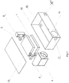
- fig. 1 presents exploded view of generator
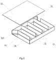
- the heat exchanger consists rectangular lower housing 12, closed by upper plate 11, to bottom of which baffles 13 are alternately fixed, beneficially parallel, whose length is smaller than width of lower housing 12, and directing baffle 14, with oblique section 141 located opposite inlet hole 15 of exhaust gases, coming out from combustion chamber 2 through the coupler 5.
- Baffles create zigzag channel for the flow of exhaust gases, whereas to outlet hole 16 of lower housing 12, by coupler 4 outlet collector 6 of exhaust gases is connected.
- the lower box 22 of generator has in side wall supplying hole 17, in front wall the hole 18 for combustion chamber 3 and the steam outlet hole 41 whereas in lower wall the exhaust outlet hole 19, connected to outlet collector 6, is located.
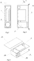
- Combustion chamber 3 has a form of 3D solid, welded from sheets, equipped with connecting holes 31 or made from segment of tube, equipped with connecting holes 31.
- combustion chamber 3 has form of casting 32 with outlet channels 33.
Claims (5)
- Der Dampferzeuger, bestehend aus einem Gehäuse, in dem sich befinden: der Wärmeaustauscher, die Verbrennungskammer und die Kollektoren, wobei sich mindestens ein Wärmeaustauscher (1) mit einem Zick-Zack-Kanalsystem zum Ableiten der Verbrennungsgase innerhalb des unteren Gehäuses (22) befindet, das von oben mit einer Abdeckung (21) geschlossen und durch ein rechteckiges Anschluß (5) mit der Verbrennungskammer (3) verbunden ist, der erwähnte Wärmeaustauscher besteht aus dem quaderförmigen unteren Gehäuse (12) mit einer Abdeckung (11) von oben geschlossen, wobei die Trennwände (13) in Form von rechtwinkligen Platten mit einem Abschnitt in Form des Buchstabens L im Wechsel mit eben diesem Abschnitt in Form des Buchstabens L zum Boden des erwähnten quaderförmigen unteren Gehäuses (12) befestigt werden, und gleichzeitig die Länge der Trennwände geringer als die Breite des quaderförmigen unteren Gehäuses (12) ist, und die Richtungstrennwand (14) einen schrägen Abschnitt (141) hat, der gegenüber der Einlassöffnung (15) für die aus der Verbrennungskammer (3) durch den Anschluß (5) abgeleiteten Abgase angeordnet ist, dagegen der Abgaskollektor (6) an die Auslassöffnung (16) des erwähnten quaderförmigen unteren Gehäuses (12) mit Hilfe des Anschlusses (4) angeschlossen wird.
- Der Dampferzeuger gemäß Anspruch 1 dadurch gekennzeichnet, dass das untere Gehäuse (22) des Dampferzeugers die untere Kammer (22) darstellt und in der Seitenwand ein Zuführungsloch (17), in der Vorderwand das Loch (18), in das die Verbrennungskammer eingeht sowie die Auslassöffnung des Dampfes (41) hat, die Auslassöffnung der Abgase (19) in der unteren Wand wird dagegen an den Abgaskollektor (6) angeschlossen.
- Der Dampferzeuger gemäß Anspruch 1 dadurch gekennzeichnet, dass die Verbrennungskammer (3) die Form eines aus Blechen zusammengeschweißten Körpers hat und mit den Anschlussöffnungen (31) ausgerüstet ist.
- Der Dampferzeuger gemäß Anspruch 1 dadurch gekennzeichnet, dass die Verbrennungskammer (3) die Form eines aus einem Rohrabschnitt gefertigten Körpers hat und mit den Anschlussöffnungen (31) ausgerüstet ist.
- Der Dampferzeuger gemäß Anspruch 3 oder 4 dadurch gekennzeichnet, dass ein Ende der Verbrennungskammer (3) die Form einen Gusses (32) mit Auslasskanälen (33) hat.
Priority Applications (2)
| Application Number | Priority Date | Filing Date | Title |
|---|---|---|---|
| PL13461526T PL2789909T3 (pl) | 2013-04-12 | 2013-04-12 | Wytwornica pary |
| EP13461526.9A EP2789909B1 (de) | 2013-04-12 | 2013-04-12 | Dampferzeuger |
Applications Claiming Priority (1)
| Application Number | Priority Date | Filing Date | Title |
|---|---|---|---|
| EP13461526.9A EP2789909B1 (de) | 2013-04-12 | 2013-04-12 | Dampferzeuger |
Publications (2)
| Publication Number | Publication Date |
|---|---|
| EP2789909A1 EP2789909A1 (de) | 2014-10-15 |
| EP2789909B1 true EP2789909B1 (de) | 2017-09-20 |
Family
ID=48143579
Family Applications (1)
| Application Number | Title | Priority Date | Filing Date |
|---|---|---|---|
| EP13461526.9A Active EP2789909B1 (de) | 2013-04-12 | 2013-04-12 | Dampferzeuger |
Country Status (2)
| Country | Link |
|---|---|
| EP (1) | EP2789909B1 (de) |
| PL (1) | PL2789909T3 (de) |
Families Citing this family (2)
| Publication number | Priority date | Publication date | Assignee | Title |
|---|---|---|---|---|
| CN105444142A (zh) * | 2015-12-28 | 2016-03-30 | 窦杰龙 | 高效密闭蒸汽循环传热装置 |
| CN107411539A (zh) * | 2017-08-23 | 2017-12-01 | 卢红兵 | 双圆式发热火盘 |
Family Cites Families (7)
| Publication number | Priority date | Publication date | Assignee | Title |
|---|---|---|---|---|
| US374615A (en) * | 1887-12-13 | mckinlay | ||
| US1558493A (en) * | 1923-08-14 | 1925-10-27 | Charles D Mosher | Air-heating apparatus |
| PL329018A1 (en) | 1998-10-02 | 2000-04-10 | Ibis Sp Z Oo | Steam generator in particular that for baking ovens |
| US6237469B1 (en) * | 2000-05-03 | 2001-05-29 | Crown Food Service Equipment Ltd. | Gas powered pressureless steam cooker |
| WO2002069065A2 (en) * | 2001-02-28 | 2002-09-06 | Porter Instrument Company, Inc. | Flow controller |
| EP1876390A1 (de) * | 2006-07-05 | 2008-01-09 | Aalborg Industries A/S | Verfahren für die Erzeugung von Dampf in einem Gasrohr-Dampfkessel und Gasrohr-Dampfkessel für die Anwendung dieses Verfahrens |
| CN101539287B (zh) | 2009-05-06 | 2011-01-05 | 清华大学 | 一种蒸汽发生器 |
-
2013
- 2013-04-12 EP EP13461526.9A patent/EP2789909B1/de active Active
- 2013-04-12 PL PL13461526T patent/PL2789909T3/pl unknown
Non-Patent Citations (1)
| Title |
|---|
| None * |
Also Published As
| Publication number | Publication date |
|---|---|
| PL2789909T3 (pl) | 2018-02-28 |
| EP2789909A1 (de) | 2014-10-15 |
Similar Documents
| Publication | Publication Date | Title |
|---|---|---|
| US10473407B2 (en) | Water heater having secondary heat exchanger | |
| JP2011506896A (ja) | 内燃機関用再循環排気ガス冷却器 | |
| EP2469215B1 (de) | Röhrenwärmetauscher | |
| RU2018130211A (ru) | Конденсационный теплообменник, оснащенный теплообменным устройством | |
| EP2241848A3 (de) | Wärmetauscher | |
| US20120145373A1 (en) | Firetube having thermal conducting passageways | |
| EP2789909B1 (de) | Dampferzeuger | |
| ITBO20130632A1 (it) | Scambiatore di calore a piastre, in particolare per caldaie a condensazione | |
| US10094619B2 (en) | Heat exchanger having arcuately and linearly arranged heat exchange tubes | |
| KR101031101B1 (ko) | 분할형 열교환기 | |
| JP5619511B2 (ja) | 間接型熱風発生機 | |
| CN102405392A (zh) | 热交换器和适用于热交换器的鳍片 | |
| CN103673723B (zh) | 壳程整体包壳结构的换热器 | |
| WO2015146286A1 (ja) | 湿分分離加熱器 | |
| CN104534667A (zh) | 冷凝式燃气采暖热水炉换热器 | |
| CN103868094A (zh) | 一种板式空气预热器及具有该预热器的烟气热能回收系统 | |
| RU162675U1 (ru) | Спиральный теплообменник | |
| RU141420U1 (ru) | Пластинчатый теплообменник | |
| CN210922246U (zh) | 一种用于石化设备的冷凝式换热器 | |
| RU126814U1 (ru) | Пластинчатый теплообменник | |
| CN107543143A (zh) | 一种净化装置 | |
| RU97478U1 (ru) | Подогреватель высокого давления для турбоустановок | |
| KR20100093276A (ko) | 수관 연관 복합 보일러 | |
| CN207703068U (zh) | 一种列管式换热器 | |
| CN203703938U (zh) | 省煤器 |
Legal Events
| Date | Code | Title | Description |
|---|---|---|---|
| PUAI | Public reference made under article 153(3) epc to a published international application that has entered the european phase |
Free format text: ORIGINAL CODE: 0009012 |
|
| 17P | Request for examination filed |
Effective date: 20130412 |
|
| AK | Designated contracting states |
Kind code of ref document: A1 Designated state(s): AL AT BE BG CH CY CZ DE DK EE ES FI FR GB GR HR HU IE IS IT LI LT LU LV MC MK MT NL NO PL PT RO RS SE SI SK SM TR |
|
| AX | Request for extension of the european patent |
Extension state: BA ME |
|
| R17P | Request for examination filed (corrected) |
Effective date: 20150409 |
|
| RBV | Designated contracting states (corrected) |
Designated state(s): AL AT BE BG CH CY CZ DE DK EE ES FI FR GB GR HR HU IE IS IT LI LT LU LV MC MK MT NL NO PL PT RO RS SE SI SK SM TR |
|
| RIC1 | Information provided on ipc code assigned before grant |
Ipc: F22B 9/00 20060101ALI20170113BHEP Ipc: F28D 21/00 20060101ALI20170113BHEP Ipc: F22B 13/04 20060101ALI20170113BHEP Ipc: F28F 9/22 20060101ALI20170113BHEP Ipc: F28F 9/16 20060101ALI20170113BHEP Ipc: F28D 9/00 20060101ALI20170113BHEP Ipc: F22B 1/18 20060101AFI20170113BHEP Ipc: F28D 7/16 20060101ALI20170113BHEP Ipc: F28D 7/08 20060101ALI20170113BHEP |
|
| GRAP | Despatch of communication of intention to grant a patent |
Free format text: ORIGINAL CODE: EPIDOSNIGR1 |
|
| STAA | Information on the status of an ep patent application or granted ep patent |
Free format text: STATUS: GRANT OF PATENT IS INTENDED |
|
| INTG | Intention to grant announced |
Effective date: 20170405 |
|
| GRAS | Grant fee paid |
Free format text: ORIGINAL CODE: EPIDOSNIGR3 |
|
| GRAA | (expected) grant |
Free format text: ORIGINAL CODE: 0009210 |
|
| STAA | Information on the status of an ep patent application or granted ep patent |
Free format text: STATUS: THE PATENT HAS BEEN GRANTED |
|
| AK | Designated contracting states |
Kind code of ref document: B1 Designated state(s): AL AT BE BG CH CY CZ DE DK EE ES FI FR GB GR HR HU IE IS IT LI LT LU LV MC MK MT NL NO PL PT RO RS SE SI SK SM TR |
|
| REG | Reference to a national code |
Ref country code: GB Ref legal event code: FG4D |
|
| REG | Reference to a national code |
Ref country code: CH Ref legal event code: EP |
|
| REG | Reference to a national code |
Ref country code: AT Ref legal event code: REF Ref document number: 930448 Country of ref document: AT Kind code of ref document: T Effective date: 20171015 |
|
| REG | Reference to a national code |
Ref country code: IE Ref legal event code: FG4D |
|
| REG | Reference to a national code |
Ref country code: DE Ref legal event code: R096 Ref document number: 602013026813 Country of ref document: DE |
|
| REG | Reference to a national code |
Ref country code: NL Ref legal event code: MP Effective date: 20170920 |
|
| PG25 | Lapsed in a contracting state [announced via postgrant information from national office to epo] |
Ref country code: HR Free format text: LAPSE BECAUSE OF FAILURE TO SUBMIT A TRANSLATION OF THE DESCRIPTION OR TO PAY THE FEE WITHIN THE PRESCRIBED TIME-LIMIT Effective date: 20170920 Ref country code: NO Free format text: LAPSE BECAUSE OF FAILURE TO SUBMIT A TRANSLATION OF THE DESCRIPTION OR TO PAY THE FEE WITHIN THE PRESCRIBED TIME-LIMIT Effective date: 20171220 Ref country code: SE Free format text: LAPSE BECAUSE OF FAILURE TO SUBMIT A TRANSLATION OF THE DESCRIPTION OR TO PAY THE FEE WITHIN THE PRESCRIBED TIME-LIMIT Effective date: 20170920 Ref country code: FI Free format text: LAPSE BECAUSE OF FAILURE TO SUBMIT A TRANSLATION OF THE DESCRIPTION OR TO PAY THE FEE WITHIN THE PRESCRIBED TIME-LIMIT Effective date: 20170920 Ref country code: LT Free format text: LAPSE BECAUSE OF FAILURE TO SUBMIT A TRANSLATION OF THE DESCRIPTION OR TO PAY THE FEE WITHIN THE PRESCRIBED TIME-LIMIT Effective date: 20170920 |
|
| REG | Reference to a national code |
Ref country code: LT Ref legal event code: MG4D |
|
| REG | Reference to a national code |
Ref country code: AT Ref legal event code: MK05 Ref document number: 930448 Country of ref document: AT Kind code of ref document: T Effective date: 20170920 |
|
| PG25 | Lapsed in a contracting state [announced via postgrant information from national office to epo] |
Ref country code: GR Free format text: LAPSE BECAUSE OF FAILURE TO SUBMIT A TRANSLATION OF THE DESCRIPTION OR TO PAY THE FEE WITHIN THE PRESCRIBED TIME-LIMIT Effective date: 20171221 Ref country code: RS Free format text: LAPSE BECAUSE OF FAILURE TO SUBMIT A TRANSLATION OF THE DESCRIPTION OR TO PAY THE FEE WITHIN THE PRESCRIBED TIME-LIMIT Effective date: 20170920 Ref country code: LV Free format text: LAPSE BECAUSE OF FAILURE TO SUBMIT A TRANSLATION OF THE DESCRIPTION OR TO PAY THE FEE WITHIN THE PRESCRIBED TIME-LIMIT Effective date: 20170920 Ref country code: BG Free format text: LAPSE BECAUSE OF FAILURE TO SUBMIT A TRANSLATION OF THE DESCRIPTION OR TO PAY THE FEE WITHIN THE PRESCRIBED TIME-LIMIT Effective date: 20171220 |
|
| PG25 | Lapsed in a contracting state [announced via postgrant information from national office to epo] |
Ref country code: NL Free format text: LAPSE BECAUSE OF FAILURE TO SUBMIT A TRANSLATION OF THE DESCRIPTION OR TO PAY THE FEE WITHIN THE PRESCRIBED TIME-LIMIT Effective date: 20170920 |
|
| PG25 | Lapsed in a contracting state [announced via postgrant information from national office to epo] |
Ref country code: RO Free format text: LAPSE BECAUSE OF FAILURE TO SUBMIT A TRANSLATION OF THE DESCRIPTION OR TO PAY THE FEE WITHIN THE PRESCRIBED TIME-LIMIT Effective date: 20170920 Ref country code: ES Free format text: LAPSE BECAUSE OF FAILURE TO SUBMIT A TRANSLATION OF THE DESCRIPTION OR TO PAY THE FEE WITHIN THE PRESCRIBED TIME-LIMIT Effective date: 20170920 Ref country code: CZ Free format text: LAPSE BECAUSE OF FAILURE TO SUBMIT A TRANSLATION OF THE DESCRIPTION OR TO PAY THE FEE WITHIN THE PRESCRIBED TIME-LIMIT Effective date: 20170920 |
|
| PG25 | Lapsed in a contracting state [announced via postgrant information from national office to epo] |
Ref country code: EE Free format text: LAPSE BECAUSE OF FAILURE TO SUBMIT A TRANSLATION OF THE DESCRIPTION OR TO PAY THE FEE WITHIN THE PRESCRIBED TIME-LIMIT Effective date: 20170920 Ref country code: SK Free format text: LAPSE BECAUSE OF FAILURE TO SUBMIT A TRANSLATION OF THE DESCRIPTION OR TO PAY THE FEE WITHIN THE PRESCRIBED TIME-LIMIT Effective date: 20170920 Ref country code: SM Free format text: LAPSE BECAUSE OF FAILURE TO SUBMIT A TRANSLATION OF THE DESCRIPTION OR TO PAY THE FEE WITHIN THE PRESCRIBED TIME-LIMIT Effective date: 20170920 Ref country code: IS Free format text: LAPSE BECAUSE OF FAILURE TO SUBMIT A TRANSLATION OF THE DESCRIPTION OR TO PAY THE FEE WITHIN THE PRESCRIBED TIME-LIMIT Effective date: 20180120 Ref country code: IT Free format text: LAPSE BECAUSE OF FAILURE TO SUBMIT A TRANSLATION OF THE DESCRIPTION OR TO PAY THE FEE WITHIN THE PRESCRIBED TIME-LIMIT Effective date: 20170920 Ref country code: AT Free format text: LAPSE BECAUSE OF FAILURE TO SUBMIT A TRANSLATION OF THE DESCRIPTION OR TO PAY THE FEE WITHIN THE PRESCRIBED TIME-LIMIT Effective date: 20170920 |
|
| REG | Reference to a national code |
Ref country code: DE Ref legal event code: R097 Ref document number: 602013026813 Country of ref document: DE |
|
| PLBE | No opposition filed within time limit |
Free format text: ORIGINAL CODE: 0009261 |
|
| STAA | Information on the status of an ep patent application or granted ep patent |
Free format text: STATUS: NO OPPOSITION FILED WITHIN TIME LIMIT |
|
| PG25 | Lapsed in a contracting state [announced via postgrant information from national office to epo] |
Ref country code: DK Free format text: LAPSE BECAUSE OF FAILURE TO SUBMIT A TRANSLATION OF THE DESCRIPTION OR TO PAY THE FEE WITHIN THE PRESCRIBED TIME-LIMIT Effective date: 20170920 |
|
| 26N | No opposition filed |
Effective date: 20180621 |
|
| REG | Reference to a national code |
Ref country code: DE Ref legal event code: R119 Ref document number: 602013026813 Country of ref document: DE |
|
| PG25 | Lapsed in a contracting state [announced via postgrant information from national office to epo] |
Ref country code: SI Free format text: LAPSE BECAUSE OF FAILURE TO SUBMIT A TRANSLATION OF THE DESCRIPTION OR TO PAY THE FEE WITHIN THE PRESCRIBED TIME-LIMIT Effective date: 20170920 Ref country code: MC Free format text: LAPSE BECAUSE OF FAILURE TO SUBMIT A TRANSLATION OF THE DESCRIPTION OR TO PAY THE FEE WITHIN THE PRESCRIBED TIME-LIMIT Effective date: 20170920 |
|
| REG | Reference to a national code |
Ref country code: CH Ref legal event code: PL |
|
| REG | Reference to a national code |
Ref country code: BE Ref legal event code: MM Effective date: 20180430 |
|
| GBPC | Gb: european patent ceased through non-payment of renewal fee |
Effective date: 20180412 |
|
| REG | Reference to a national code |
Ref country code: IE Ref legal event code: MM4A |
|
| PG25 | Lapsed in a contracting state [announced via postgrant information from national office to epo] |
Ref country code: DE Free format text: LAPSE BECAUSE OF NON-PAYMENT OF DUE FEES Effective date: 20181101 Ref country code: LU Free format text: LAPSE BECAUSE OF NON-PAYMENT OF DUE FEES Effective date: 20180412 |
|
| PG25 | Lapsed in a contracting state [announced via postgrant information from national office to epo] |
Ref country code: LI Free format text: LAPSE BECAUSE OF NON-PAYMENT OF DUE FEES Effective date: 20180430 Ref country code: GB Free format text: LAPSE BECAUSE OF NON-PAYMENT OF DUE FEES Effective date: 20180412 Ref country code: BE Free format text: LAPSE BECAUSE OF NON-PAYMENT OF DUE FEES Effective date: 20180430 Ref country code: CH Free format text: LAPSE BECAUSE OF NON-PAYMENT OF DUE FEES Effective date: 20180430 |
|
| PG25 | Lapsed in a contracting state [announced via postgrant information from national office to epo] |
Ref country code: IE Free format text: LAPSE BECAUSE OF NON-PAYMENT OF DUE FEES Effective date: 20180412 Ref country code: FR Free format text: LAPSE BECAUSE OF NON-PAYMENT OF DUE FEES Effective date: 20180430 |
|
| PG25 | Lapsed in a contracting state [announced via postgrant information from national office to epo] |
Ref country code: MT Free format text: LAPSE BECAUSE OF NON-PAYMENT OF DUE FEES Effective date: 20180412 |
|
| PG25 | Lapsed in a contracting state [announced via postgrant information from national office to epo] |
Ref country code: TR Free format text: LAPSE BECAUSE OF FAILURE TO SUBMIT A TRANSLATION OF THE DESCRIPTION OR TO PAY THE FEE WITHIN THE PRESCRIBED TIME-LIMIT Effective date: 20170920 |
|
| PG25 | Lapsed in a contracting state [announced via postgrant information from national office to epo] |
Ref country code: PT Free format text: LAPSE BECAUSE OF FAILURE TO SUBMIT A TRANSLATION OF THE DESCRIPTION OR TO PAY THE FEE WITHIN THE PRESCRIBED TIME-LIMIT Effective date: 20170920 Ref country code: HU Free format text: LAPSE BECAUSE OF FAILURE TO SUBMIT A TRANSLATION OF THE DESCRIPTION OR TO PAY THE FEE WITHIN THE PRESCRIBED TIME-LIMIT; INVALID AB INITIO Effective date: 20130412 |
|
| PG25 | Lapsed in a contracting state [announced via postgrant information from national office to epo] |
Ref country code: MK Free format text: LAPSE BECAUSE OF NON-PAYMENT OF DUE FEES Effective date: 20170920 Ref country code: CY Free format text: LAPSE BECAUSE OF FAILURE TO SUBMIT A TRANSLATION OF THE DESCRIPTION OR TO PAY THE FEE WITHIN THE PRESCRIBED TIME-LIMIT Effective date: 20170920 |
|
| PG25 | Lapsed in a contracting state [announced via postgrant information from national office to epo] |
Ref country code: AL Free format text: LAPSE BECAUSE OF FAILURE TO SUBMIT A TRANSLATION OF THE DESCRIPTION OR TO PAY THE FEE WITHIN THE PRESCRIBED TIME-LIMIT Effective date: 20170920 |
|
| PGFP | Annual fee paid to national office [announced via postgrant information from national office to epo] |
Ref country code: PL Payment date: 20230323 Year of fee payment: 11 |