EP2789909B1 - Steam generator - Google Patents
Steam generator Download PDFInfo
- Publication number
- EP2789909B1 EP2789909B1 EP13461526.9A EP13461526A EP2789909B1 EP 2789909 B1 EP2789909 B1 EP 2789909B1 EP 13461526 A EP13461526 A EP 13461526A EP 2789909 B1 EP2789909 B1 EP 2789909B1
- Authority
- EP
- European Patent Office
- Prior art keywords
- combustion chamber
- lower housing
- steam generator
- hole
- exhaust gases
- Prior art date
- Legal status (The legal status is an assumption and is not a legal conclusion. Google has not performed a legal analysis and makes no representation as to the accuracy of the status listed.)
- Active
Links
Images


Classifications
-
- F—MECHANICAL ENGINEERING; LIGHTING; HEATING; WEAPONS; BLASTING
- F22—STEAM GENERATION
- F22B—METHODS OF STEAM GENERATION; STEAM BOILERS
- F22B1/00—Methods of steam generation characterised by form of heating method
- F22B1/02—Methods of steam generation characterised by form of heating method by exploitation of the heat content of hot heat carriers
- F22B1/18—Methods of steam generation characterised by form of heating method by exploitation of the heat content of hot heat carriers the heat carrier being a hot gas, e.g. waste gas such as exhaust gas of internal-combustion engines
-
- A—HUMAN NECESSITIES
- A21—BAKING; EDIBLE DOUGHS
- A21B—BAKERS' OVENS; MACHINES OR EQUIPMENT FOR BAKING
- A21B3/00—Parts or accessories of ovens
- A21B3/04—Air-treatment devices for ovens, e.g. regulating humidity
-
- F—MECHANICAL ENGINEERING; LIGHTING; HEATING; WEAPONS; BLASTING
- F22—STEAM GENERATION
- F22B—METHODS OF STEAM GENERATION; STEAM BOILERS
- F22B13/00—Steam boilers of fire-box type, i.e. the combustion of fuel being performed in a chamber or fire-box with subsequent flue(s) or fire tube(s), both chamber or fire-box and flues or fire tubes being built-in in the boiler body
- F22B13/04—Steam boilers of fire-box type, i.e. the combustion of fuel being performed in a chamber or fire-box with subsequent flue(s) or fire tube(s), both chamber or fire-box and flues or fire tubes being built-in in the boiler body mounted in fixed position with the boiler body disposed substantially horizontally
-
- F—MECHANICAL ENGINEERING; LIGHTING; HEATING; WEAPONS; BLASTING
- F22—STEAM GENERATION
- F22B—METHODS OF STEAM GENERATION; STEAM BOILERS
- F22B9/00—Steam boilers of fire-tube type, i.e. the flue gas from a combustion chamber outside the boiler body flowing through tubes built-in in the boiler body
-
- F—MECHANICAL ENGINEERING; LIGHTING; HEATING; WEAPONS; BLASTING
- F28—HEAT EXCHANGE IN GENERAL
- F28D—HEAT-EXCHANGE APPARATUS, NOT PROVIDED FOR IN ANOTHER SUBCLASS, IN WHICH THE HEAT-EXCHANGE MEDIA DO NOT COME INTO DIRECT CONTACT
- F28D21/00—Heat-exchange apparatus not covered by any of the groups F28D1/00 - F28D20/00
- F28D21/0001—Recuperative heat exchangers
- F28D21/0003—Recuperative heat exchangers the heat being recuperated from exhaust gases
-
- F—MECHANICAL ENGINEERING; LIGHTING; HEATING; WEAPONS; BLASTING
- F28—HEAT EXCHANGE IN GENERAL
- F28D—HEAT-EXCHANGE APPARATUS, NOT PROVIDED FOR IN ANOTHER SUBCLASS, IN WHICH THE HEAT-EXCHANGE MEDIA DO NOT COME INTO DIRECT CONTACT
- F28D7/00—Heat-exchange apparatus having stationary tubular conduit assemblies for both heat-exchange media, the media being in contact with different sides of a conduit wall
- F28D7/08—Heat-exchange apparatus having stationary tubular conduit assemblies for both heat-exchange media, the media being in contact with different sides of a conduit wall the conduits being otherwise bent, e.g. in a serpentine or zig-zag
- F28D7/082—Heat-exchange apparatus having stationary tubular conduit assemblies for both heat-exchange media, the media being in contact with different sides of a conduit wall the conduits being otherwise bent, e.g. in a serpentine or zig-zag with serpentine or zig-zag configuration
-
- F—MECHANICAL ENGINEERING; LIGHTING; HEATING; WEAPONS; BLASTING
- F28—HEAT EXCHANGE IN GENERAL
- F28D—HEAT-EXCHANGE APPARATUS, NOT PROVIDED FOR IN ANOTHER SUBCLASS, IN WHICH THE HEAT-EXCHANGE MEDIA DO NOT COME INTO DIRECT CONTACT
- F28D7/00—Heat-exchange apparatus having stationary tubular conduit assemblies for both heat-exchange media, the media being in contact with different sides of a conduit wall
- F28D7/16—Heat-exchange apparatus having stationary tubular conduit assemblies for both heat-exchange media, the media being in contact with different sides of a conduit wall the conduits being arranged in parallel spaced relation
- F28D7/1684—Heat-exchange apparatus having stationary tubular conduit assemblies for both heat-exchange media, the media being in contact with different sides of a conduit wall the conduits being arranged in parallel spaced relation the conduits having a non-circular cross-section
- F28D7/1692—Heat-exchange apparatus having stationary tubular conduit assemblies for both heat-exchange media, the media being in contact with different sides of a conduit wall the conduits being arranged in parallel spaced relation the conduits having a non-circular cross-section with particular pattern of flow of the heat exchange media, e.g. change of flow direction
-
- F—MECHANICAL ENGINEERING; LIGHTING; HEATING; WEAPONS; BLASTING
- F28—HEAT EXCHANGE IN GENERAL
- F28F—DETAILS OF HEAT-EXCHANGE AND HEAT-TRANSFER APPARATUS, OF GENERAL APPLICATION
- F28F9/00—Casings; Header boxes; Auxiliary supports for elements; Auxiliary members within casings
- F28F9/02—Header boxes; End plates
- F28F9/04—Arrangements for sealing elements into header boxes or end plates
- F28F9/16—Arrangements for sealing elements into header boxes or end plates by permanent joints, e.g. by rolling
- F28F9/165—Arrangements for sealing elements into header boxes or end plates by permanent joints, e.g. by rolling by using additional preformed parts, e.g. sleeves, gaskets
-
- F—MECHANICAL ENGINEERING; LIGHTING; HEATING; WEAPONS; BLASTING
- F28—HEAT EXCHANGE IN GENERAL
- F28D—HEAT-EXCHANGE APPARATUS, NOT PROVIDED FOR IN ANOTHER SUBCLASS, IN WHICH THE HEAT-EXCHANGE MEDIA DO NOT COME INTO DIRECT CONTACT
- F28D9/00—Heat-exchange apparatus having stationary plate-like or laminated conduit assemblies for both heat-exchange media, the media being in contact with different sides of a conduit wall
- F28D9/0062—Heat-exchange apparatus having stationary plate-like or laminated conduit assemblies for both heat-exchange media, the media being in contact with different sides of a conduit wall the conduits for one heat-exchange medium being formed by spaced plates with inserted elements
- F28D9/0068—Heat-exchange apparatus having stationary plate-like or laminated conduit assemblies for both heat-exchange media, the media being in contact with different sides of a conduit wall the conduits for one heat-exchange medium being formed by spaced plates with inserted elements with means for changing flow direction of one heat exchange medium, e.g. using deflecting zones
Definitions
- the present invention relates to a steam generator, containing heat exchanger, used especially in baking equipment.
- a steam generator containing a housing, inside of which a heat exchanger, a combustion chamber and collectors are located, is characterized in that at least one heat exchanger is located inside of a lower housing, closed with an upper cover.
- Said heat exchanger consists of a rectangular lower housing, closed with an upper cover.
- baffles and a directing baffle in the form of rectangular plates with L-shaped section are alternately fixed by means of said L-shaped section.
- the length of the baffles is smaller than the width of the lower housing, and the directing baffle has an oblique section, located opposite to the inlet of exhaust gases coming from the combustion chamber through the connector.
- the baffles create zigzag channel for exhaust gases.
- the exhaust gases collector is connected through a coupler.
- the lower box of the generator has a supplying hole in a side wall, a hole in a front wall for receiving the combustion chamber and an outlet hole for steam, whereas an outlet hole for exhaust gases in a bottom wall, connected with outlet collector, is located.
- the combustion chamber has a shape of a solid, made from welded sheets and equipped with connecting holes.
- the combustion chamber has a shape of a solid, made from tube segment and equipped with connecting holes.
- the one end of the combustion chamber has a shape of casting with exhaust channels.
- Steam generator thanks to usage of heat exchanger, which has a form of tight box with baffles, is characterized by significantly higher efficiency and power, which may be adjusted by changing the number of baffles. Design of generator allows for reduction of production costs, also by elimination of production waste.
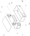
- fig. 1 presents exploded view of generator
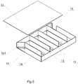
- the heat exchanger consists rectangular lower housing 12, closed by upper plate 11, to bottom of which baffles 13 are alternately fixed, beneficially parallel, whose length is smaller than width of lower housing 12, and directing baffle 14, with oblique section 141 located opposite inlet hole 15 of exhaust gases, coming out from combustion chamber 2 through the coupler 5.
- Baffles create zigzag channel for the flow of exhaust gases, whereas to outlet hole 16 of lower housing 12, by coupler 4 outlet collector 6 of exhaust gases is connected.
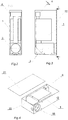
- the lower box 22 of generator has in side wall supplying hole 17, in front wall the hole 18 for combustion chamber 3 and the steam outlet hole 41 whereas in lower wall the exhaust outlet hole 19, connected to outlet collector 6, is located.
- Combustion chamber 3 has a form of 3D solid, welded from sheets, equipped with connecting holes 31 or made from segment of tube, equipped with connecting holes 31.
- combustion chamber 3 has form of casting 32 with outlet channels 33.
Description
- The present invention relates to a steam generator, containing heat exchanger, used especially in baking equipment.
- There is known from the Polish application No P.
329018 - There is known from description of the European application No
EP 2428728 a steam generator consisting of heat exchanger, liquid collector and steam collector. Heat exchanger is connected with few heat exchange subassemblies with the same structure. The heat exchange subassembly contains spiral tubes, central cylinder and a sleeve. Spiral tubes are concentric, with different radii and are helically located in annular space between the central cylinder and the sleeve, to create at least one concentric heat exchanging pillar. One end of liquid collector is connected with the main pipe, feeding water tubes, and the other end of liquid collector is connected with bundle of spiral tubes. One end of steam collector is connected with the main steam pipe, and the other end with a bundle of spiral tubes. - Document
US 6 237 469 B1 discloses a steam generator with a lower housing and baffles. - A steam generator, according to the invention, containing a housing, inside of which a heat exchanger, a combustion chamber and collectors are located, is characterized in that at least one heat exchanger is located inside of a lower housing, closed with an upper cover. Said heat exchanger consists of a rectangular lower housing, closed with an upper cover. To the bottom of said lower housing, baffles and a directing baffle in the form of rectangular plates with L-shaped section are alternately fixed by means of said L-shaped section. The length of the baffles is smaller than the width of the lower housing, and the directing baffle has an oblique section, located opposite to the inlet of exhaust gases coming from the combustion chamber through the connector. The baffles create zigzag channel for exhaust gases. To the outlet hole of the lower housing, the exhaust gases collector is connected through a coupler.
- The lower box of the generator has a supplying hole in a side wall, a hole in a front wall for receiving the combustion chamber and an outlet hole for steam, whereas an outlet hole for exhaust gases in a bottom wall, connected with outlet collector, is located.
- Preferably, the combustion chamber has a shape of a solid, made from welded sheets and equipped with connecting holes.
- Preferably, the combustion chamber has a shape of a solid, made from tube segment and equipped with connecting holes.
- Preferably, the one end of the combustion chamber has a shape of casting with exhaust channels.
- Steam generator, according to invention, thanks to usage of heat exchanger, which has a form of tight box with baffles, is characterized by significantly higher efficiency and power, which may be adjusted by changing the number of baffles. Design of generator allows for reduction of production costs, also by elimination of production waste.
- The subject of invention is presented on the drawing, where
fig. 1 presents exploded view of generator,fig. 2 - section A-A fromfig. 3, fig. 3 - top view of generator without upper cover,fig. 4 - view of generator with removed upper cover,fig. 5 - exploded view of heat exchanger,fig. 6 - top view of exchanger with shown media flow direction,fig. 7 - rear view of heat exchanger,fig. 8 - section A-A fromfig. 6, fig. 9 - detail B fromfig. 8 ,fig. 10 up tofig. 13 - shapes of combustion chamber. - Inside
lower box 22, closed withupper cover 21, are located twoheat exchangers 1, connected byrectangular couplers 5 tocombustion chamber 3. The heat exchanger consists rectangularlower housing 12, closed byupper plate 11, to bottom of whichbaffles 13 are alternately fixed, beneficially parallel, whose length is smaller than width oflower housing 12, and directingbaffle 14, withoblique section 141 located oppositeinlet hole 15 of exhaust gases, coming out from combustion chamber 2 through thecoupler 5. Baffles create zigzag channel for the flow of exhaust gases, whereas tooutlet hole 16 oflower housing 12, bycoupler 4outlet collector 6 of exhaust gases is connected. - The
lower box 22 of generator has in sidewall supplying hole 17, in front wall thehole 18 forcombustion chamber 3 and thesteam outlet hole 41 whereas in lower wall theexhaust outlet hole 19, connected tooutlet collector 6, is located. -
Combustion chamber 3 has a form of 3D solid, welded from sheets, equipped with connectingholes 31 or made from segment of tube, equipped with connectingholes 31. - Preferably,
combustion chamber 3 has form ofcasting 32 withoutlet channels 33.
Claims (5)
- A steam generator containing a housing, inside of which a heat exchanger, a combustion chamber and collectors are located, wherein at least one heat exchanger (1) with zigzag channels for exhaust gases is located inside of a lower housing (22), closed with an upper cover (21), and connected by a rectangular coupler (5) with the combustion chamber (3), said heat exchanger consists of a cuboid lower housing (12) closed with an upper cover (11), wherein to the bottom of said cuboid lower housing (12), baffles (13) in the form of rectangular plates with L-shaped section are alternately fixed by means of said L-shaped section, and at the same time the length of the baffles is smaller than the width of the cuboid lower housing (12), and a directing baffle (14) has an oblique section (141) located opposite to the inlet hole (15) of exhaust gases coming from the combustion chamber (3) through the coupler (5), whereas to the outlet hole (16) of said cuboid lower housing (12), the exhaust gases collector (6) is connected through a coupler (4).
- A steam generator, according to claim 1, characterized in that the lower housing (22) of the generator is a lower box (22) and has a supplying hole (17) in a side wall, a hole (18) in a front wall for receiving the combustion chamber (3) and a steam outlet hole (41), whereas an exhaust gases outlet hole (19) in lower wall is connected with the exhaust collector (6).
- A steam generator, according to claim 1, characterized in that the combustion chamber (3) has a form of solid, made of welded sheets and equipped with connecting holes (31).
- A steam generator, according to claim 1, characterized in that the combustion chamber (3) has a shape of solid, made from segment of tube and equipped with connecting holes (31).
- A steam generator, according to claim 3 or 4, characterized in that the one end of the combustion chamber (3) has a form of casting (32) with outlet channels (33).
Priority Applications (2)
| Application Number | Priority Date | Filing Date | Title |
|---|---|---|---|
| EP13461526.9A EP2789909B1 (en) | 2013-04-12 | 2013-04-12 | Steam generator |
| PL13461526T PL2789909T3 (en) | 2013-04-12 | 2013-04-12 | Steam generator |
Applications Claiming Priority (1)
| Application Number | Priority Date | Filing Date | Title |
|---|---|---|---|
| EP13461526.9A EP2789909B1 (en) | 2013-04-12 | 2013-04-12 | Steam generator |
Publications (2)
| Publication Number | Publication Date |
|---|---|
| EP2789909A1 EP2789909A1 (en) | 2014-10-15 |
| EP2789909B1 true EP2789909B1 (en) | 2017-09-20 |
Family
ID=48143579
Family Applications (1)
| Application Number | Title | Priority Date | Filing Date |
|---|---|---|---|
| EP13461526.9A Active EP2789909B1 (en) | 2013-04-12 | 2013-04-12 | Steam generator |
Country Status (2)
| Country | Link |
|---|---|
| EP (1) | EP2789909B1 (en) |
| PL (1) | PL2789909T3 (en) |
Families Citing this family (2)
| Publication number | Priority date | Publication date | Assignee | Title |
|---|---|---|---|---|
| CN105444142A (en) * | 2015-12-28 | 2016-03-30 | 窦杰龙 | Efficient closed steam cycle heat transfer device |
| CN107411539A (en) * | 2017-08-23 | 2017-12-01 | 卢红兵 | Double-circul type heating fiery disk |
Family Cites Families (7)
| Publication number | Priority date | Publication date | Assignee | Title |
|---|---|---|---|---|
| US374615A (en) * | 1887-12-13 | mckinlay | ||
| US1558493A (en) * | 1923-08-14 | 1925-10-27 | Charles D Mosher | Air-heating apparatus |
| PL329018A1 (en) | 1998-10-02 | 2000-04-10 | Ibis Sp Z Oo | Steam generator in particular that for baking ovens |
| US6237469B1 (en) * | 2000-05-03 | 2001-05-29 | Crown Food Service Equipment Ltd. | Gas powered pressureless steam cooker |
| AU2002242304A1 (en) * | 2001-02-28 | 2002-09-12 | Porter Instrument Company, Inc. | Manifolded fluid delivery system |
| EP1876390A1 (en) * | 2006-07-05 | 2008-01-09 | Aalborg Industries A/S | Method of producing steam in a gas tube steam boiler and gas tube steam boiler for implementing said method |
| CN101539287B (en) | 2009-05-06 | 2011-01-05 | 清华大学 | Steam generator |
-
2013
- 2013-04-12 EP EP13461526.9A patent/EP2789909B1/en active Active
- 2013-04-12 PL PL13461526T patent/PL2789909T3/en unknown
Non-Patent Citations (1)
| Title |
|---|
| None * |
Also Published As
| Publication number | Publication date |
|---|---|
| PL2789909T3 (en) | 2018-02-28 |
| EP2789909A1 (en) | 2014-10-15 |
Similar Documents
| Publication | Publication Date | Title |
|---|---|---|
| US10473407B2 (en) | Water heater having secondary heat exchanger | |
| JP2011506896A (en) | Recirculation exhaust gas cooler for internal combustion engines | |
| EP2469215B1 (en) | Tube heat exchanger | |
| RU2018130211A (en) | CONDENSATION HEAT EXCHANGER EQUIPPED WITH A HEAT EXCHANGER | |
| CN100559076C (en) | Subcritical pressure pouring boiler furnace | |
| EP2241848A3 (en) | Heat exchanger | |
| US20120145373A1 (en) | Firetube having thermal conducting passageways | |
| EP2789909B1 (en) | Steam generator | |
| US10094619B2 (en) | Heat exchanger having arcuately and linearly arranged heat exchange tubes | |
| KR101031101B1 (en) | separation type heat exchanger | |
| ITBO20130632A1 (en) | PLATE HEAT EXCHANGER, IN PARTICULAR FOR CONDENSING BOILERS | |
| JP5619511B2 (en) | Indirect hot air generator | |
| CN102405392A (en) | Heat exchanger and fin suitable for use in a heat exchanger | |
| CN103673723B (en) | The heat exchanger of the overall containment structure of shell side | |
| CN104534667A (en) | Condensing gas heating water heating furnace heat exchanger | |
| RU162986U1 (en) | SPIRAL HEAT EXCHANGER | |
| CN103868094A (en) | Plate-type air pre-heater and flue gas heat energy recovery system with plate-type air pre-heater | |
| RU162675U1 (en) | SPIRAL HEAT EXCHANGER | |
| RU141420U1 (en) | PLATE HEAT EXCHANGER | |
| CN210922246U (en) | Condensing heat exchanger for petrochemical equipment | |
| RU126814U1 (en) | PLATE HEAT EXCHANGER | |
| CN107543143A (en) | A kind of purifier | |
| US20180058775A1 (en) | Heat exchanger constructive arrangement | |
| RU97478U1 (en) | HIGH PRESSURE HEATER FOR TURBO INSTALLATIONS | |
| KR20100093276A (en) | Boiler |
Legal Events
| Date | Code | Title | Description |
|---|---|---|---|
| PUAI | Public reference made under article 153(3) epc to a published international application that has entered the european phase |
Free format text: ORIGINAL CODE: 0009012 |
|
| 17P | Request for examination filed |
Effective date: 20130412 |
|
| AK | Designated contracting states |
Kind code of ref document: A1 Designated state(s): AL AT BE BG CH CY CZ DE DK EE ES FI FR GB GR HR HU IE IS IT LI LT LU LV MC MK MT NL NO PL PT RO RS SE SI SK SM TR |
|
| AX | Request for extension of the european patent |
Extension state: BA ME |
|
| R17P | Request for examination filed (corrected) |
Effective date: 20150409 |
|
| RBV | Designated contracting states (corrected) |
Designated state(s): AL AT BE BG CH CY CZ DE DK EE ES FI FR GB GR HR HU IE IS IT LI LT LU LV MC MK MT NL NO PL PT RO RS SE SI SK SM TR |
|
| RIC1 | Information provided on ipc code assigned before grant |
Ipc: F22B 9/00 20060101ALI20170113BHEP Ipc: F28D 21/00 20060101ALI20170113BHEP Ipc: F22B 13/04 20060101ALI20170113BHEP Ipc: F28F 9/22 20060101ALI20170113BHEP Ipc: F28F 9/16 20060101ALI20170113BHEP Ipc: F28D 9/00 20060101ALI20170113BHEP Ipc: F22B 1/18 20060101AFI20170113BHEP Ipc: F28D 7/16 20060101ALI20170113BHEP Ipc: F28D 7/08 20060101ALI20170113BHEP |
|
| GRAP | Despatch of communication of intention to grant a patent |
Free format text: ORIGINAL CODE: EPIDOSNIGR1 |
|
| STAA | Information on the status of an ep patent application or granted ep patent |
Free format text: STATUS: GRANT OF PATENT IS INTENDED |
|
| INTG | Intention to grant announced |
Effective date: 20170405 |
|
| GRAS | Grant fee paid |
Free format text: ORIGINAL CODE: EPIDOSNIGR3 |
|
| GRAA | (expected) grant |
Free format text: ORIGINAL CODE: 0009210 |
|
| STAA | Information on the status of an ep patent application or granted ep patent |
Free format text: STATUS: THE PATENT HAS BEEN GRANTED |
|
| AK | Designated contracting states |
Kind code of ref document: B1 Designated state(s): AL AT BE BG CH CY CZ DE DK EE ES FI FR GB GR HR HU IE IS IT LI LT LU LV MC MK MT NL NO PL PT RO RS SE SI SK SM TR |
|
| REG | Reference to a national code |
Ref country code: GB Ref legal event code: FG4D |
|
| REG | Reference to a national code |
Ref country code: CH Ref legal event code: EP |
|
| REG | Reference to a national code |
Ref country code: AT Ref legal event code: REF Ref document number: 930448 Country of ref document: AT Kind code of ref document: T Effective date: 20171015 |
|
| REG | Reference to a national code |
Ref country code: IE Ref legal event code: FG4D |
|
| REG | Reference to a national code |
Ref country code: DE Ref legal event code: R096 Ref document number: 602013026813 Country of ref document: DE |
|
| REG | Reference to a national code |
Ref country code: NL Ref legal event code: MP Effective date: 20170920 |
|
| PG25 | Lapsed in a contracting state [announced via postgrant information from national office to epo] |
Ref country code: HR Free format text: LAPSE BECAUSE OF FAILURE TO SUBMIT A TRANSLATION OF THE DESCRIPTION OR TO PAY THE FEE WITHIN THE PRESCRIBED TIME-LIMIT Effective date: 20170920 Ref country code: NO Free format text: LAPSE BECAUSE OF FAILURE TO SUBMIT A TRANSLATION OF THE DESCRIPTION OR TO PAY THE FEE WITHIN THE PRESCRIBED TIME-LIMIT Effective date: 20171220 Ref country code: SE Free format text: LAPSE BECAUSE OF FAILURE TO SUBMIT A TRANSLATION OF THE DESCRIPTION OR TO PAY THE FEE WITHIN THE PRESCRIBED TIME-LIMIT Effective date: 20170920 Ref country code: FI Free format text: LAPSE BECAUSE OF FAILURE TO SUBMIT A TRANSLATION OF THE DESCRIPTION OR TO PAY THE FEE WITHIN THE PRESCRIBED TIME-LIMIT Effective date: 20170920 Ref country code: LT Free format text: LAPSE BECAUSE OF FAILURE TO SUBMIT A TRANSLATION OF THE DESCRIPTION OR TO PAY THE FEE WITHIN THE PRESCRIBED TIME-LIMIT Effective date: 20170920 |
|
| REG | Reference to a national code |
Ref country code: LT Ref legal event code: MG4D |
|
| REG | Reference to a national code |
Ref country code: AT Ref legal event code: MK05 Ref document number: 930448 Country of ref document: AT Kind code of ref document: T Effective date: 20170920 |
|
| PG25 | Lapsed in a contracting state [announced via postgrant information from national office to epo] |
Ref country code: GR Free format text: LAPSE BECAUSE OF FAILURE TO SUBMIT A TRANSLATION OF THE DESCRIPTION OR TO PAY THE FEE WITHIN THE PRESCRIBED TIME-LIMIT Effective date: 20171221 Ref country code: RS Free format text: LAPSE BECAUSE OF FAILURE TO SUBMIT A TRANSLATION OF THE DESCRIPTION OR TO PAY THE FEE WITHIN THE PRESCRIBED TIME-LIMIT Effective date: 20170920 Ref country code: LV Free format text: LAPSE BECAUSE OF FAILURE TO SUBMIT A TRANSLATION OF THE DESCRIPTION OR TO PAY THE FEE WITHIN THE PRESCRIBED TIME-LIMIT Effective date: 20170920 Ref country code: BG Free format text: LAPSE BECAUSE OF FAILURE TO SUBMIT A TRANSLATION OF THE DESCRIPTION OR TO PAY THE FEE WITHIN THE PRESCRIBED TIME-LIMIT Effective date: 20171220 |
|
| PG25 | Lapsed in a contracting state [announced via postgrant information from national office to epo] |
Ref country code: NL Free format text: LAPSE BECAUSE OF FAILURE TO SUBMIT A TRANSLATION OF THE DESCRIPTION OR TO PAY THE FEE WITHIN THE PRESCRIBED TIME-LIMIT Effective date: 20170920 |
|
| PG25 | Lapsed in a contracting state [announced via postgrant information from national office to epo] |
Ref country code: RO Free format text: LAPSE BECAUSE OF FAILURE TO SUBMIT A TRANSLATION OF THE DESCRIPTION OR TO PAY THE FEE WITHIN THE PRESCRIBED TIME-LIMIT Effective date: 20170920 Ref country code: ES Free format text: LAPSE BECAUSE OF FAILURE TO SUBMIT A TRANSLATION OF THE DESCRIPTION OR TO PAY THE FEE WITHIN THE PRESCRIBED TIME-LIMIT Effective date: 20170920 Ref country code: CZ Free format text: LAPSE BECAUSE OF FAILURE TO SUBMIT A TRANSLATION OF THE DESCRIPTION OR TO PAY THE FEE WITHIN THE PRESCRIBED TIME-LIMIT Effective date: 20170920 |
|
| PG25 | Lapsed in a contracting state [announced via postgrant information from national office to epo] |
Ref country code: EE Free format text: LAPSE BECAUSE OF FAILURE TO SUBMIT A TRANSLATION OF THE DESCRIPTION OR TO PAY THE FEE WITHIN THE PRESCRIBED TIME-LIMIT Effective date: 20170920 Ref country code: SK Free format text: LAPSE BECAUSE OF FAILURE TO SUBMIT A TRANSLATION OF THE DESCRIPTION OR TO PAY THE FEE WITHIN THE PRESCRIBED TIME-LIMIT Effective date: 20170920 Ref country code: SM Free format text: LAPSE BECAUSE OF FAILURE TO SUBMIT A TRANSLATION OF THE DESCRIPTION OR TO PAY THE FEE WITHIN THE PRESCRIBED TIME-LIMIT Effective date: 20170920 Ref country code: IS Free format text: LAPSE BECAUSE OF FAILURE TO SUBMIT A TRANSLATION OF THE DESCRIPTION OR TO PAY THE FEE WITHIN THE PRESCRIBED TIME-LIMIT Effective date: 20180120 Ref country code: IT Free format text: LAPSE BECAUSE OF FAILURE TO SUBMIT A TRANSLATION OF THE DESCRIPTION OR TO PAY THE FEE WITHIN THE PRESCRIBED TIME-LIMIT Effective date: 20170920 Ref country code: AT Free format text: LAPSE BECAUSE OF FAILURE TO SUBMIT A TRANSLATION OF THE DESCRIPTION OR TO PAY THE FEE WITHIN THE PRESCRIBED TIME-LIMIT Effective date: 20170920 |
|
| REG | Reference to a national code |
Ref country code: DE Ref legal event code: R097 Ref document number: 602013026813 Country of ref document: DE |
|
| PLBE | No opposition filed within time limit |
Free format text: ORIGINAL CODE: 0009261 |
|
| STAA | Information on the status of an ep patent application or granted ep patent |
Free format text: STATUS: NO OPPOSITION FILED WITHIN TIME LIMIT |
|
| PG25 | Lapsed in a contracting state [announced via postgrant information from national office to epo] |
Ref country code: DK Free format text: LAPSE BECAUSE OF FAILURE TO SUBMIT A TRANSLATION OF THE DESCRIPTION OR TO PAY THE FEE WITHIN THE PRESCRIBED TIME-LIMIT Effective date: 20170920 |
|
| 26N | No opposition filed |
Effective date: 20180621 |
|
| REG | Reference to a national code |
Ref country code: DE Ref legal event code: R119 Ref document number: 602013026813 Country of ref document: DE |
|
| PG25 | Lapsed in a contracting state [announced via postgrant information from national office to epo] |
Ref country code: SI Free format text: LAPSE BECAUSE OF FAILURE TO SUBMIT A TRANSLATION OF THE DESCRIPTION OR TO PAY THE FEE WITHIN THE PRESCRIBED TIME-LIMIT Effective date: 20170920 Ref country code: MC Free format text: LAPSE BECAUSE OF FAILURE TO SUBMIT A TRANSLATION OF THE DESCRIPTION OR TO PAY THE FEE WITHIN THE PRESCRIBED TIME-LIMIT Effective date: 20170920 |
|
| REG | Reference to a national code |
Ref country code: CH Ref legal event code: PL |
|
| REG | Reference to a national code |
Ref country code: BE Ref legal event code: MM Effective date: 20180430 |
|
| GBPC | Gb: european patent ceased through non-payment of renewal fee |
Effective date: 20180412 |
|
| REG | Reference to a national code |
Ref country code: IE Ref legal event code: MM4A |
|
| PG25 | Lapsed in a contracting state [announced via postgrant information from national office to epo] |
Ref country code: DE Free format text: LAPSE BECAUSE OF NON-PAYMENT OF DUE FEES Effective date: 20181101 Ref country code: LU Free format text: LAPSE BECAUSE OF NON-PAYMENT OF DUE FEES Effective date: 20180412 |
|
| PG25 | Lapsed in a contracting state [announced via postgrant information from national office to epo] |
Ref country code: LI Free format text: LAPSE BECAUSE OF NON-PAYMENT OF DUE FEES Effective date: 20180430 Ref country code: GB Free format text: LAPSE BECAUSE OF NON-PAYMENT OF DUE FEES Effective date: 20180412 Ref country code: BE Free format text: LAPSE BECAUSE OF NON-PAYMENT OF DUE FEES Effective date: 20180430 Ref country code: CH Free format text: LAPSE BECAUSE OF NON-PAYMENT OF DUE FEES Effective date: 20180430 |
|
| PG25 | Lapsed in a contracting state [announced via postgrant information from national office to epo] |
Ref country code: IE Free format text: LAPSE BECAUSE OF NON-PAYMENT OF DUE FEES Effective date: 20180412 Ref country code: FR Free format text: LAPSE BECAUSE OF NON-PAYMENT OF DUE FEES Effective date: 20180430 |
|
| PG25 | Lapsed in a contracting state [announced via postgrant information from national office to epo] |
Ref country code: MT Free format text: LAPSE BECAUSE OF NON-PAYMENT OF DUE FEES Effective date: 20180412 |
|
| PG25 | Lapsed in a contracting state [announced via postgrant information from national office to epo] |
Ref country code: TR Free format text: LAPSE BECAUSE OF FAILURE TO SUBMIT A TRANSLATION OF THE DESCRIPTION OR TO PAY THE FEE WITHIN THE PRESCRIBED TIME-LIMIT Effective date: 20170920 |
|
| PG25 | Lapsed in a contracting state [announced via postgrant information from national office to epo] |
Ref country code: PT Free format text: LAPSE BECAUSE OF FAILURE TO SUBMIT A TRANSLATION OF THE DESCRIPTION OR TO PAY THE FEE WITHIN THE PRESCRIBED TIME-LIMIT Effective date: 20170920 Ref country code: HU Free format text: LAPSE BECAUSE OF FAILURE TO SUBMIT A TRANSLATION OF THE DESCRIPTION OR TO PAY THE FEE WITHIN THE PRESCRIBED TIME-LIMIT; INVALID AB INITIO Effective date: 20130412 |
|
| PG25 | Lapsed in a contracting state [announced via postgrant information from national office to epo] |
Ref country code: MK Free format text: LAPSE BECAUSE OF NON-PAYMENT OF DUE FEES Effective date: 20170920 Ref country code: CY Free format text: LAPSE BECAUSE OF FAILURE TO SUBMIT A TRANSLATION OF THE DESCRIPTION OR TO PAY THE FEE WITHIN THE PRESCRIBED TIME-LIMIT Effective date: 20170920 |
|
| PG25 | Lapsed in a contracting state [announced via postgrant information from national office to epo] |
Ref country code: AL Free format text: LAPSE BECAUSE OF FAILURE TO SUBMIT A TRANSLATION OF THE DESCRIPTION OR TO PAY THE FEE WITHIN THE PRESCRIBED TIME-LIMIT Effective date: 20170920 |
|
| PGFP | Annual fee paid to national office [announced via postgrant information from national office to epo] |
Ref country code: PL Payment date: 20230323 Year of fee payment: 11 |