EP2789569A2 - Installationseinrichtung für eine leistungselektronische Vorrichtung - Google Patents
Installationseinrichtung für eine leistungselektronische Vorrichtung Download PDFInfo
- Publication number
- EP2789569A2 EP2789569A2 EP20140160799 EP14160799A EP2789569A2 EP 2789569 A2 EP2789569 A2 EP 2789569A2 EP 20140160799 EP20140160799 EP 20140160799 EP 14160799 A EP14160799 A EP 14160799A EP 2789569 A2 EP2789569 A2 EP 2789569A2
- Authority
- EP
- European Patent Office
- Prior art keywords
- support
- ramp
- enclosure
- arrangement
- arrangement according
- Prior art date
- Legal status (The legal status is an assumption and is not a legal conclusion. Google has not performed a legal analysis and makes no representation as to the accuracy of the status listed.)
- Withdrawn
Links
Images
Classifications
-
- B—PERFORMING OPERATIONS; TRANSPORTING
- B65—CONVEYING; PACKING; STORING; HANDLING THIN OR FILAMENTARY MATERIAL
- B65G—TRANSPORT OR STORAGE DEVICES, e.g. CONVEYORS FOR LOADING OR TIPPING, SHOP CONVEYOR SYSTEMS OR PNEUMATIC TUBE CONVEYORS
- B65G69/00—Auxiliary measures taken, or devices used, in connection with loading or unloading
-
- H—ELECTRICITY
- H05—ELECTRIC TECHNIQUES NOT OTHERWISE PROVIDED FOR
- H05K—PRINTED CIRCUITS; CASINGS OR CONSTRUCTIONAL DETAILS OF ELECTRIC APPARATUS; MANUFACTURE OF ASSEMBLAGES OF ELECTRICAL COMPONENTS
- H05K7/00—Constructional details common to different types of electric apparatus
- H05K7/14—Mounting supporting structure in casing or on frame or rack
- H05K7/1422—Printed circuit boards receptacles, e.g. stacked structures, electronic circuit modules or box like frames
- H05K7/1427—Housings
- H05K7/1432—Housings specially adapted for power drive units or power converters
- H05K7/14325—Housings specially adapted for power drive units or power converters for cabinets or racks
-
- H—ELECTRICITY
- H05—ELECTRIC TECHNIQUES NOT OTHERWISE PROVIDED FOR
- H05K—PRINTED CIRCUITS; CASINGS OR CONSTRUCTIONAL DETAILS OF ELECTRIC APPARATUS; MANUFACTURE OF ASSEMBLAGES OF ELECTRICAL COMPONENTS
- H05K7/00—Constructional details common to different types of electric apparatus
- H05K7/14—Mounting supporting structure in casing or on frame or rack
- H05K7/1422—Printed circuit boards receptacles, e.g. stacked structures, electronic circuit modules or box like frames
- H05K7/1427—Housings
- H05K7/1432—Housings specially adapted for power drive units or power converters
Definitions
- the object of the present invention is an arrangement for installing a structural unit belonging to a power electronics device or forming a power electronics device into an electrical installation enclosure.
- High-powered power electronics devices such as frequency converters or their separate structural units, are normally installed into electrical installation enclosures that function as, inter alia, a protection against contact guaranteeing the electrical safety of the user.
- the enclosures generally comprise for these prefabricated mechanical supporting structures and electrical connections to other submodules and to external connectors.
- a plinth space in which, inter alia, electric cables are disposed.
- a plinth can be e.g. 10cm high, and the aforementioned electrical devices are installed above it.
- Lifting high-powered structural units, which can weigh up to many hundreds of kilograms, to this height can be problematic, particularly in a servicing situation in which the space available in front of the installation enclosure can be cramped.
- a corresponding hindrance to installation can also be a support bar, situated at floor level, belonging to the enclosure structure, which bar forms a step in the passage leading inside the enclosure.
- a known solution for getting a heavy structural unit to installation height is collaborative lifting by a number of people. In cramped spaces, however, generally at most 2 people can simultaneously grip the device, so that this method is sufficient for up to perhaps approx. 100 kg. For lifting heavier devices a crane is needed. For a servicing situation both arrangements - getting a number of people to the site, and transporting a crane to the installation spaces - are problematic.
- One problem is also the long period of servicing work required by conventional methods, during which period the process in which the device being serviced is used generally has to be stopped.
- the aim of the present invention is to solve the aforementioned problem and to provide a novel arrangement that facilitates the installation work of a heavy power electronics device, especially in on-site conditions.
- the aim is achieved with the arrangement according to the invention, which is characterized by what is stated in the characterization part of the independent claim.
- Other preferred embodiments of the invention are the objects of the dependent claims.
- a sloping support ramp is utilized, along which a heavy structural unit of a power electronics device is moved into position in an enclosure or moved out of it.
- a structural unit can slide along the support ramp or it can be provided with wheels for making the moving easier.
- the support ramp can be detachable, and it can be used only during installation work. According to a preferred embodiment of the invention some part belonging to the enclosure structure is used as a support ramp, which part is partly or wholly detached from its original position for the duration of a servicing situation.
- This type of part can be e.g. a protection against contact plate installable in front of the bare connections of a device or a detachable bottom part of the front door of the installation enclosure, which bottom part can be a perforated part of the ventilation system of the enclosure.
- the support ramp can, of course, also be a separate part that does not belong to the enclosure structure.
- a structural unit is lowered down along the support ramp, or lifted upwards along it towards an enclosure, by the aid of an elongated screw, in which case very little use of manual force is needed.
- the invention makes it possible for only one fitter to replace a heavy structural unit in on-site conditions, and with very little use of force.
- the time needed for the replacement work is short when compared to prior art.
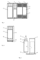
- Fig. 1 presents a typical row of installation enclosures of a power electronics device, e.g. of a frequency converter, and the placement of its various structural units inside the enclosures.
- a power electronics device e.g. of a frequency converter
- this figure, as well as the other figures in this document, have been presented in a simplified form without e.g. the fixing arrangements for devices, which are obvious to a person skilled in the art.
- the height dimensions and depth dimensions of installation enclosures 11 - 14 disposed in the same row are normally same, e.g. height 2000 mm and depth 600 mm, respectively, and the width dimension varies according to the need of the structural unit disposed inside the enclosure.
- a large-sized structural unit 15 is installed inside the wide (e.g. 800 mm) enclosure 11, and a structural unit 16 of smaller size inside the narrow (e.g. 600 mm) enclosure 12.
- the enclosures 11 and 12 are described without front doors, the enclosures 13 and 14 correspondingly with front doors.
- the forced air ventilation possibly required by the device inside an installation enclosure, is normally accomplished via the perforated front panels 17, 19 disposed in the front doors 18.
- FIG. 2 presents in more detail the placement of a structural unit 15 inside an enclosure 11.
- An installation enclosure is generally of rectangular prism shape, the edges functioning as the frame of which prism are assembled from straight metal frame bars, an example of one of which is the front bar 21 presented in the figure.
- Walls that are generally fabricated from thin metal sheets, such as the side wall 23 according to the figure, and that protect the inside spaces of the enclosure are fixed to these frame bars.
- a base plate 22, e.g. according to the figure, for supporting the device disposed inside the enclosure can be fixed to the frame bars.
- connection of power electronics devices to an external circuit are normally situated in the bottom part of the device, owing to which a perforated plate-shaped part 20 according to the figure is often disposed in front of the bottom part of a device, which plate-shaped part functions as a protection against contact and protects the user from inadvertently touching electrically live parts also when the enclosure door is open.
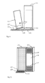
- Fig. 3 presents a method according to prior art, with which a heavy device is lifted inside an installation enclosure.
- a crane (not presented) raises, by the aid of a rope arrangement 24 and lifting lugs 25 fixed to the device, the structural unit 15 into the air, in which case it can be pushed inside the enclosure 11, in the direction of the arrow drawn with a dashed line in the figure, onto the base plate 22 into its final position marked with a dashed line.
- Fig. 4 presents an arrangement according to the present invention for moving a heavy device into or out of an enclosure.
- a sloping support ramp 126 is used in the arrangement, on top of which ramp the transfer of the structural unit 115 takes place.
- the support ramp is placed between the floor 125 and a support point that belongs to the installation enclosure and is situated above the floor level, such as the base plate 122, the support bar ( Fig. 2 , part 21) of the front part 121 of the base plate, said bar functioning as a step, or a corresponding support point.
- the bottom part of the device can have small wheels 127, or e.g. roller bearings with the outer rims rolling against the metal edge of the support ramp can be used as such.
- the moving can, of course, take place also by sliding, without wheels.
- the support ramp according to the invention can be a separate part that the servicing personnel bring with them.
- a part of the enclosure structure is used as a support ramp, which part is partly or wholly detached from its original position.
- Fig. 5 presents two installation enclosures 111, 112, the forced air ventilation possibly needed by the devices disposed inside which enclosures can be accomplished via the perforated front panels 117, 119 disposed in the front doors 118.
- the protection against contact plate 120 is used as a support ramp, the top end of which plate is detached from its fastenings and after that is turned against the floor while the fasteners 132, 133 of the bottom end remain in their position.
- the arrangement is useful in that a separate part, and therefore one easily lost accidentally, is not needed, but instead a support ramp is always available in a servicing situation.
Landscapes
- Engineering & Computer Science (AREA)
- Mechanical Engineering (AREA)
- Microelectronics & Electronic Packaging (AREA)
- Handcart (AREA)
- Casings For Electric Apparatus (AREA)
- Automatic Cycles, And Cycles In General (AREA)
- Current-Collector Devices For Electrically Propelled Vehicles (AREA)
Applications Claiming Priority (1)
| Application Number | Priority Date | Filing Date | Title |
|---|---|---|---|
| FIU20134089U FI10539U1 (fi) | 2013-04-11 | 2013-04-11 | Tehoelektroniikkalaitteen asennusjärjestely |
Publications (2)
| Publication Number | Publication Date |
|---|---|
| EP2789569A2 true EP2789569A2 (de) | 2014-10-15 |
| EP2789569A3 EP2789569A3 (de) | 2015-01-21 |
Family
ID=50442333
Family Applications (1)
| Application Number | Title | Priority Date | Filing Date |
|---|---|---|---|
| EP20140160799 Withdrawn EP2789569A3 (de) | 2013-04-11 | 2014-03-20 | Installationseinrichtung für eine leistungselektronische Vorrichtung |
Country Status (3)
| Country | Link |
|---|---|
| US (1) | US20140304927A1 (de) |
| EP (1) | EP2789569A3 (de) |
| FI (1) | FI10539U1 (de) |
Cited By (1)
| Publication number | Priority date | Publication date | Assignee | Title |
|---|---|---|---|---|
| CN104214487A (zh) * | 2014-08-29 | 2014-12-17 | 成都市晶林科技有限公司 | 便于移动的摄像头安装机构 |
Families Citing this family (1)
| Publication number | Priority date | Publication date | Assignee | Title |
|---|---|---|---|---|
| JP2017103857A (ja) * | 2015-11-30 | 2017-06-08 | 富士電機株式会社 | 電力変換装置 |
Family Cites Families (12)
| Publication number | Priority date | Publication date | Assignee | Title |
|---|---|---|---|---|
| US3210456A (en) * | 1963-02-26 | 1965-10-05 | Mc Graw Edison Co | Ground level housing for electrical apparatus |
| US4078678A (en) * | 1976-10-12 | 1978-03-14 | Tordella Joseph R | Van platform housing |
| US5133459A (en) * | 1990-09-20 | 1992-07-28 | Dell Usa Corporation | Shipping container for an article including a ramp and cushion assembly |
| US5299511A (en) * | 1992-06-03 | 1994-04-05 | Dallman Industrial Corporation | Bellcrank assembly for moving an ATM module |
| US5443312A (en) * | 1994-04-07 | 1995-08-22 | Schluter; Robert J. | Rack assembly for facilitating access to wall and cabinet-mounted serviceable equipment |
| US20070164540A1 (en) * | 2003-03-21 | 2007-07-19 | Ron Van Dijk | Container |
| US7310843B1 (en) * | 2006-05-12 | 2007-12-25 | Eagle Manufacturing Company | Loading ramp for standardized intermodal freight containers |
| US20080217949A1 (en) * | 2007-03-09 | 2008-09-11 | Kobrehel Michael D | Powered Tailgate Ramp |
| US20080277391A1 (en) * | 2007-05-07 | 2008-11-13 | International Business Machines Corporation | Mobile, Robotic Crate |
| US20090064428A1 (en) * | 2007-09-11 | 2009-03-12 | William Dale Hoffman | Cabana tailgate ramp |
| US8091942B2 (en) * | 2008-11-19 | 2012-01-10 | Gumbo Product Development, Inc. | Recreational vehicle with ramp door |
| TW201137568A (en) * | 2010-04-21 | 2011-11-01 | Hon Hai Prec Ind Co Ltd | Server cabinet |
-
2013
- 2013-04-11 FI FIU20134089U patent/FI10539U1/fi active IP Right Grant
-
2014
- 2014-03-20 EP EP20140160799 patent/EP2789569A3/de not_active Withdrawn
- 2014-04-02 US US14/243,312 patent/US20140304927A1/en not_active Abandoned
Non-Patent Citations (1)
| Title |
|---|
| None |
Cited By (1)
| Publication number | Priority date | Publication date | Assignee | Title |
|---|---|---|---|---|
| CN104214487A (zh) * | 2014-08-29 | 2014-12-17 | 成都市晶林科技有限公司 | 便于移动的摄像头安装机构 |
Also Published As
| Publication number | Publication date |
|---|---|
| EP2789569A3 (de) | 2015-01-21 |
| US20140304927A1 (en) | 2014-10-16 |
| FI10539U1 (fi) | 2014-07-11 |
Similar Documents
| Publication | Publication Date | Title |
|---|---|---|
| EP2789569A2 (de) | Installationseinrichtung für eine leistungselektronische Vorrichtung | |
| JP2010208764A (ja) | エレベータの制御装置 | |
| KR101466137B1 (ko) | 인입형 특고압 전력케이블의 변전소 설치형 절연트레이 | |
| EP2110907B1 (de) | Elektrische Versorgungsvorrichtungsanordnung | |
| CN202888708U (zh) | 一种可移固定式低压开关柜 | |
| CN108400531A (zh) | 一种便于拆卸安装的配电柜 | |
| CA2994754C (en) | CONVERSION SYSTEM FOR AN ELECTRICAL DISTRIBUTION INSTALLATION | |
| US20150162727A1 (en) | Withdrawable control compartment for switchgear | |
| US11165228B2 (en) | Dynamic track end stop | |
| US8432666B2 (en) | Method of manufacturing a switchgear panel | |
| JP2017046458A (ja) | 制御装置取替方法 | |
| KR100947842B1 (ko) | 변압기의 외함 구조 | |
| JP2016050102A (ja) | エレベータの仮設作業床装置 | |
| KR20170060840A (ko) | 제어반 수납캐비넷 | |
| JP6509161B2 (ja) | エレベーターのリニューアル方法 | |
| DE102015014712A1 (de) | Wand -und systemkomponententragendes Elektrifizierungssystem mit integrierter Schnellmontagefunktion von elektrischen Systemkomponenten | |
| JP5869844B2 (ja) | 屋外形閉鎖配電盤 | |
| CN205623002U (zh) | 一种电力工控信息安全整机装置 | |
| CN211240454U (zh) | 自动检测设备电控箱 | |
| JP2014064399A (ja) | 制御装置取替方法および制御装置 | |
| CN217509214U (zh) | 一种快装机柜 | |
| KR20090005371U (ko) | 전장 제어 실습 장치 | |
| JP7159930B2 (ja) | 制御装置用架台および制御装置取替方法 | |
| KR101379276B1 (ko) | 수배전반의 중전기 이송 장치 | |
| KR101316886B1 (ko) | 수배전반 구조 |
Legal Events
| Date | Code | Title | Description |
|---|---|---|---|
| PUAI | Public reference made under article 153(3) epc to a published international application that has entered the european phase |
Free format text: ORIGINAL CODE: 0009012 |
|
| 17P | Request for examination filed |
Effective date: 20140320 |
|
| AK | Designated contracting states |
Kind code of ref document: A2 Designated state(s): AL AT BE BG CH CY CZ DE DK EE ES FI FR GB GR HR HU IE IS IT LI LT LU LV MC MK MT NL NO PL PT RO RS SE SI SK SM TR |
|
| AX | Request for extension of the european patent |
Extension state: BA ME |
|
| R17P | Request for examination filed (corrected) |
Effective date: 20141110 |
|
| RBV | Designated contracting states (corrected) |
Designated state(s): AL AT BE BG CH CY CZ DE DK EE ES FI FR GB GR HR HU IE IS IT LI LT LU LV MC MK MT NL NO PL PT RO RS SE SI SK SM TR |
|
| PUAL | Search report despatched |
Free format text: ORIGINAL CODE: 0009013 |
|
| R17P | Request for examination filed (corrected) |
Effective date: 20140320 |
|
| AK | Designated contracting states |
Kind code of ref document: A3 Designated state(s): AL AT BE BG CH CY CZ DE DK EE ES FI FR GB GR HR HU IE IS IT LI LT LU LV MC MK MT NL NO PL PT RO RS SE SI SK SM TR |
|
| AX | Request for extension of the european patent |
Extension state: BA ME |
|
| RIC1 | Information provided on ipc code assigned before grant |
Ipc: B60B 33/00 20060101ALI20141215BHEP Ipc: H05K 7/14 20060101ALI20141215BHEP Ipc: B65G 69/30 20060101ALI20141215BHEP Ipc: B66F 9/00 20060101AFI20141215BHEP Ipc: B65G 69/28 20060101ALI20141215BHEP |
|
| R17P | Request for examination filed (corrected) |
Effective date: 20150702 |
|
| RBV | Designated contracting states (corrected) |
Designated state(s): AL AT BE BG CH CY CZ DE DK EE ES FI FR GB GR HR HU IE IS IT LI LT LU LV MC MK MT NL NO PL PT RO RS SE SI SK SM TR |
|
| RAP1 | Party data changed (applicant data changed or rights of an application transferred) |
Owner name: VACON OY |
|
| STAA | Information on the status of an ep patent application or granted ep patent |
Free format text: STATUS: THE APPLICATION IS DEEMED TO BE WITHDRAWN |
|
| 18D | Application deemed to be withdrawn |
Effective date: 20171003 |