EP2789554A1 - Container with lid - Google Patents
Container with lid Download PDFInfo
- Publication number
- EP2789554A1 EP2789554A1 EP14450012.1A EP14450012A EP2789554A1 EP 2789554 A1 EP2789554 A1 EP 2789554A1 EP 14450012 A EP14450012 A EP 14450012A EP 2789554 A1 EP2789554 A1 EP 2789554A1
- Authority
- EP
- European Patent Office
- Prior art keywords
- lid
- bearing
- container
- container according
- friction
- Prior art date
- Legal status (The legal status is an assumption and is not a legal conclusion. Google has not performed a legal analysis and makes no representation as to the accuracy of the status listed.)
- Granted
Links
- 230000007704 transition Effects 0.000 claims abstract description 5
- 230000015572 biosynthetic process Effects 0.000 claims 12
- 238000005755 formation reaction Methods 0.000 claims 12
- 235000015095 lager Nutrition 0.000 description 10
- 238000013016 damping Methods 0.000 description 1
- 230000001419 dependent effect Effects 0.000 description 1
- 210000005069 ears Anatomy 0.000 description 1
Images


Classifications
-
- B—PERFORMING OPERATIONS; TRANSPORTING
- B65—CONVEYING; PACKING; STORING; HANDLING THIN OR FILAMENTARY MATERIAL
- B65F—GATHERING OR REMOVAL OF DOMESTIC OR LIKE REFUSE
- B65F1/00—Refuse receptacles; Accessories therefor
- B65F1/14—Other constructional features; Accessories
- B65F1/16—Lids or covers
- B65F1/1646—Lids or covers provided with means for mounting on receptacles, e.g. hinges
-
- B—PERFORMING OPERATIONS; TRANSPORTING
- B65—CONVEYING; PACKING; STORING; HANDLING THIN OR FILAMENTARY MATERIAL
- B65F—GATHERING OR REMOVAL OF DOMESTIC OR LIKE REFUSE
- B65F1/00—Refuse receptacles; Accessories therefor
- B65F1/14—Other constructional features; Accessories
- B65F2001/1653—Constructional features of lids or covers
- B65F2001/1661—Constructional features of lids or covers relating to noise reduction, e.g. during opening or closing
-
- B—PERFORMING OPERATIONS; TRANSPORTING
- B65—CONVEYING; PACKING; STORING; HANDLING THIN OR FILAMENTARY MATERIAL
- B65F—GATHERING OR REMOVAL OF DOMESTIC OR LIKE REFUSE
- B65F1/00—Refuse receptacles; Accessories therefor
- B65F1/14—Other constructional features; Accessories
- B65F2001/1653—Constructional features of lids or covers
- B65F2001/1669—Constructional features of lids or covers relating to means for fixing or latching the lid or cover in a certain angle
Landscapes
- Engineering & Computer Science (AREA)
- Mechanical Engineering (AREA)
- Closures For Containers (AREA)
- Table Devices Or Equipment (AREA)
- Devices For Use In Laboratory Experiments (AREA)
Abstract
Um einen Deckel (3) eines Behälters (1), insbesondere eines Müllbehälters, am Ende seiner Schließbewegung durch Reibung in seinem Lager (4) zu dämpfen, sodass dieser ohne lautes Geräusch auf den Rand der Öffnung des Körpers (2) des Behälters in Anlage kommt, sind im Bereich des Lagers (4) des Deckels (3) am Behälter (1) Flächen (9, 10) vorgesehen, die vorspringende Bereiche (Berge 12) und rückspringende Bereiche (Täler 13), zwischen denen kontinuierliche Übergänge vorgesehen sind, vorgesehen. Im Endabschnitt der Schließbewegung des Deckels (3) gelangen Berge (12) an den einander zugekehrten Flächen (9, 10) der Lager (4) des Deckels (3) am Behälter (1) Reibung erzeugend in Anlage aneinander, sodass die Bewegung des Deckels (3) in seine Schließstellung gedämpft ist.To dampen a cover (3) of a container (1), in particular a refuse container, at the end of its closing movement by friction in its bearing (4) so that it rests without loud noise on the edge of the opening of the body (2) of the container comes, in the area of the bearing (4) of the lid (3) on the container (1) surfaces (9, 10) are provided, the projecting areas (mountains 12) and recessed areas (valleys 13), between which continuous transitions are provided, intended. In the end portion of the closing movement of the lid (3) reach mountains (12) on the mutually facing surfaces (9, 10) of the bearing (4) of the lid (3) on the container (1) generating friction in abutment against each other, so that the movement of the lid (3) is damped to its closed position.
Description
Die Erfindung betrifft einen Behälter mit einem Deckel mit den Merkmalen des einleitenden Teils von Anspruch 1.The invention relates to a container with a lid having the features of the introductory part of
Derartige Behälter sind beispielsweise als Müllbehälter bekannt.Such containers are known for example as refuse containers.
Beim Schließen des Behälters, wobei der Deckel über die Öffnung des Behälters geklappt wird, entsteht ein nicht unbeträchtliches Geräusch, wenn der Deckel nicht gehalten, sondern frei fallen gelassen wird. Ein ähnliches lautes Geräusch entsteht durch Aufprallen des Deckels am Behälter, wenn der Deckel nicht langsam und vorsichtig vollständig geöffnet wird, also in die Stellung geschwenkt wird, in der er neben der Rückwand des Behälters nach unten hängt.When closing the container, wherein the lid is folded over the opening of the container, a not inconsiderable noise, if the lid is not held, but is dropped freely. A similar loud noise is produced by the lid bouncing off the container if the lid is not opened slowly and carefully, ie pivoted to the position in which it hangs down next to the rear wall of the container.
Aus der
Die außen liegende Scheibe der Scheibenbremse ist an dem Deckel - dessen Verbindungssteg - und die innen liegende Scheibe ist am Rumpfsteg des Behälterkörpers befestigt.The outer disc of the disc brake is on the lid - whose connecting web - and the inner disc is attached to the fuselage of the container body.
Der aus der
Bei der
Der Erfindung liegt die Aufgabe zugrunde, einen Behälter der eingangs genannten Gattung zur Verfügung zu stellen, bei dem die Geräuschentwicklung wenigstens beim Schließen des Deckels vermieden oder wenigstens verringert ist.The invention has for its object to provide a container of the type mentioned available in which the noise is avoided or at least reduced at least when closing the lid.
Gelöst wird diese Aufgabe erfindungsgemäß mit einem Behälter, welcher die Merkmale von Anspruch 1 aufweist.This object is achieved according to the invention with a container having the features of
Bevorzugte und vorteilhafte Ausgestaltungen der Erfindung sind Gegenstand der Unteransprüche.Preferred and advantageous embodiments of the invention are the subject of the dependent claims.
Da bei dem erfindungsgemäßen Behälter wenigstens die Bewegung des Deckels in die Schließstellung (der Deckel ist die Öffnung des Behälters abdeckend angeordnet) und gegebenenfalls auch die Bewegung des Deckels in die vollständig geöffnete Stellung (der Deckel hängt an der Rückseite des Behälters nach unten) wenigstens im Endbereich der jeweiligen Bewegung des Deckels in die genannten Stellungen durch einen Bremsvorgang gedämpft wird, ist die Geräuschentwicklung verringert, wenn nicht zur Gänze vermieden.Since in the container according to the invention at least the movement of the lid in the closed position (the lid is arranged covering the opening of the container) and optionally also the movement of the lid in the fully open position (the lid depends on the back of the container down) at least in End region of the respective movement of the lid is damped in the said positions by a braking operation, the noise is reduced, if not completely avoided.
Reibung, die das Bewegen des Deckels in die Schließstellung und gegebenenfalls auch in die vollständig geöffnete Stellung dämpfend bremst, kann dadurch erreicht werden, dass im Bereich der Lager des Deckels am Behälter bereichsweise einander gegenüberliegende Flächen vorgesehen sind, die insbesondere im Endbereich der Bewegungen des Deckels in die Schließstellung und in die vollständig geöffnete Stellung aneinander Reibung erzeugend in Anlage gelangen.Friction, which dampens the movement of the lid in the closed position and optionally also in the fully open position, can be achieved that in the region of the bearings of the lid on the container partially opposite surfaces are provided, in particular in the end region of the movements of the lid in the closed position and in the fully open position to each other generate friction in abutment.
Dies kann beispielsweise dadurch erreicht werden, dass an einander zugekehrten Flächen des Lagers des Deckels und des Behälters vorspringende Bereiche ("Berge") und gegebenenfalls auch rückspringende Bereiche ("Täler") vorgesehen sind. Wenn im Lager des Deckels Berge, die an einerseits am Deckel und andererseits an am Behälter angeordneten Teilen des Lagers des Deckels am Behälter vorgesehen sind, aneinander anliegen, entsteht Reibung, die das Bewegen des Deckels dämpft, sodass dieser beispielsweise gebremst und geräuschlos geschlossen wird.This can be achieved, for example, by providing surfaces of the bearing of the lid and of the Container projecting areas ("mountains") and possibly also recessed areas ("valleys") are provided. If in the camp of the lid mountains, which are provided on the one hand on the lid and on the other hand arranged on the container parts of the bearing of the lid on the container, abut each other, creates friction that damps the movement of the lid so that it is braked and closed silently, for example.
Insbesondere können Berge (und ggf. Täler) an einander zugekehrten Flächen von Lageraugen des Deckels und Flanschen im Bereich von Lagerzapfen am Körper des Behälters vorgesehen sein. Daher sind gesonderte Bauteile (wie bei der
Die einander zugekehrten Flächen der Lageraugen am Behälter können als zu der Schwenkachse des Deckels (definiert durch die Lagerzapfen) im Wesentlichen konzentrische Ringflächen, also nach Art von Zylindermantelflächen, ausgebildet sein.The mutually facing surfaces of the bearing eyes on the container can be formed as to the pivot axis of the lid (defined by the bearing pin) substantially concentric annular surfaces, ie in the manner of cylinder jacket surfaces.
Es besteht auch die Möglichkeit, die Berge (und ggf. die Täler) an Kreisringflächen vorzusehen, die zur durch die Lagerzapfen definierten Schwenkachse des Deckels im Wesentlichen senkrecht stehen.There is also the possibility of providing the mountains (and possibly the valleys) on annular surfaces which are substantially perpendicular to the pivot axis of the cover defined by the bearing pin.
Vorteilhaft bei der erfindungsgemäßen Ausbildung des Behälters ist es, dass das Schwenken des Deckels in den Teilen seines Schwenkbereiches, in denen einander keine Berge, sondern insbesondere Täler in den einander zugekehrten Flächen gegenüberliegen, nicht gebremst wird, also die Bewegung des Deckels nicht behindert ist.An advantage of the inventive design of the container is that the pivoting of the lid in the parts of its pivoting range in which no mountains, but in particular opposite valleys in the facing surfaces, is not slowed down, so the movement of the lid is not hindered.
Die die Bewegung des Deckels dämpfende und bremsende Reibung zwischen Bergen an Lagerteilen am Deckel und am Behälter tritt beim erfindungsgemäßen Behälter insbesondere und bevorzugt im Endbereich der Bewegungen des Deckels in die Schließstellung oder die vollständig geöffnete Stellung auf.The movement of the lid dampening and braking friction between mountains on bearing parts on the lid and the container occurs in the container according to the invention in particular and preferably in the end of the movements of the lid in the closed position or the fully open position.
Die Erfindung ermöglicht es auch, den Deckel durch Reibung in einer Stellung zu halten, in der dieser quer zur Öffnung nach oben ab steht, indem in dieser Stellung des Deckels Berge der einander zugekehrten Flächen an Lagerteilen am Behälter und am Deckel einander gegenüberliegen.The invention also makes it possible to hold the lid by friction in a position in which this is transverse to the opening from above by mountains of the facing surfaces of bearing parts on the container and the lid opposite each other in this position of the lid.
Wenn im Vorliegenden in Zusammenhang mit dem erfindungsgemäßen Behälter von "rückspringenden Bereichen" oder "Tälern" in einander zugekehrten Teilen oder Flächen an Teilen des Lagers des Deckels am Körper des Behälters gesprochen wird, sind damit Bereich in einander zugekehrten Teilen oder an einander zugekehrten Flächen von Teilen des Lagers des Deckels am Körper des erfindungsgemäßen Behälters gemeint, die, wenn sie einander gegenüberliegend angeordnet sind, voneinander Abstand ("Spiel") haben. Es ist bei der Erfindung vorteilhaft, wenn die "rückspringenden Bereiche" oder "Täler" in den einander zugekehrten Teilen oder an einander zugekehrten Flächen von Teilen des Lagers des Deckels am Körper des Behälters "körperlich" verwirklicht sind. Diese Bereiche können auch Unterbrechungen in einander zugekehrten Flächen des Lagers des Deckels am Körper des Behälters sein, die zwischen/neben "vorspringenden Bereichen" oder "Bergen" in diesen Flächen angeordnet sind. In dieser Ausführungsform sind es Teile des Lagers des Deckels am Körper des Behälters, welche die "vorspringenden Bereiche" oder "Berge" bilden.When in the present context in connection with the container according to the invention of "recessed areas" or "valleys" in facing parts or surfaces on parts of the bearing of the lid on the body of the container is spoken, so are area in facing parts or facing surfaces of Meaning of the bearing of the lid on the body of the container according to the invention, which, when they are arranged opposite each other, have a mutual distance ("play"). It is advantageous in the invention, when the "recessed areas" or "valleys" in the facing parts or on mutually facing surfaces of parts of the bearing of the lid on the body of the container "physically" are realized. These areas can also be interruptions in mutually facing surfaces of the bearing of the lid on the body of the container, which are arranged between / next to "projecting areas" or "mountains" in these areas. In this embodiment, there are parts of the bearing of the lid on the body of the container, which form the "projecting areas" or "mountains".
Weitere Einzelheiten und Merkmale der Erfindung ergeben sich aus der nachstehenden Beschreibung bevorzugter Ausführungsbeispiele anhand der Zeichnungen. Es zeigt:
- Fig. 1
- den oberen Bereich eines Müllbehälters mit dem Lager des Deckels,
- Fig. 2
- eine Einzelheit des Lagers des Deckels bei geschlossenem Deckel,
- Fig. 3
- das Lager von rechts der
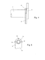
Fig. 2 aus gesehen, - Fig. 4
- eine Einzelheit des Lagers bei nach oben abstehendem Deckel,
- Fig. 5
- das Lager von rechts der
Fig. 4 aus gesehen, - Fig. 6
- eine Einzelheit des Lagers bei vollständig geöffnetem Deckel,
- Fig. 7
- das Lager von rechts der
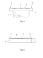
Fig. 6 aus gesehen, - Fig. 8
- einen Flansch im Bereich des Lagerzapfens und
- Fig. 9
- ein Lagerauge.
- Fig. 1
- the upper portion of a garbage container with the bearing of the lid,
- Fig. 2
- a detail of the bearing of the lid with the lid closed,
- Fig. 3
- the camp from the right
Fig. 2 seen from - Fig. 4
- a detail of the warehouse with upwardly projecting lid,
- Fig. 5
- the camp from the right
Fig. 4 seen from - Fig. 6
- a detail of the warehouse with the lid fully open,
- Fig. 7
- the camp from the right
Fig. 6 seen from - Fig. 8
- a flange in the area of the journal and
- Fig. 9
- a bearing eye.
Ein Behälter 1, der im Beispiel als Müllbehälter ausgebildet ist, besitzt einen Körper 2, dessen - in Gebrauchlage oben liegender-Öffnung ein Deckel 3 zugeordnet ist.A
Der Deckel 3 ist über ein Lager 4 mit Lageraugen 5 und Lagerzapfen 6 gegenüber dem Körper 2 des Behälters 1 schwenkbar. Die Lagerzapfen 6 sind durch die Lageraugen 5 von beiden Enden her in ein Rohr 7 gesteckt, das über mehrere Arme 8 am Körper 2 des Behälters 1 befestigt ist. Die Lageraugen 5 sind mit aufeinander zu ("nach innen") weisenden, kreisringförmigen Flächen 9 nach außen weisenden Flächen 10 an Flanschen 11 an den freien Enden der das Rohr 7 haltenden Arme 8 zugekehrt, die im Bereich der Lagerzapfen 6 am Rohr 7 angeordnet sind. In
Der Deckel 1 kann aus seiner (in
Im Beispiel weist der Deckel 3 des Behälters 1 (Müllbehälters) im Bereich seiner - durch die Lagerzapfen 6 definierten - Achse, um die er gegenüber dem Körper 2 des Behälters zum Öffnen und Schließen verschwenkt werden kann, die zwei Lageraugen 5 auf. Mit diesen Lageraugen 5 sitzt der Deckel 3 schwenkbar auf den Lagerzapfen 6, wobei innerhalb der Lageraugen 5 die Flansche 11 an den äußeren Armen 8 vorgesehen sind, über welche das die Lagerzapfen 6 aufnehmende Rohr 7 mit dem Körper 2 des Behälters 1 verbunden ist. Die den Lageraugen 5 unmittelbar benachbarten Arme 8 weisen die Flansche 11 auf, an welchen den inneren Flächen 9 der Lageraugen 5 zugekehrte Flächen 10 vorgesehen sind (vgl.
Ziel ist es, den Deckel 3 beim Schließen, insbesondere im Endbereich der Schließbewegung, zu "bremsen", damit dieser auch dann möglichst geräuschlos und gedämpft in seine die Öffnung im Körper 2 des Behälters 1 verschließende Stellung gelangt, wenn er nicht mit der Hand gehalten/geführt wird. In gleicher Weise soll der zur Gänze geöffnete Deckel 3, also wenn er auf die Seite des Lagers 4 des Deckels 3 am Behälter 1 nach unten geschwenkt wird, im Endbereich dieser Schwenkbewegung gebremst werden, und nicht ungebremst auf den Körper 2 des Behälters 1 aufprallen, auch wenn er nicht gehalten/geführt wird.The aim is to "slow down" the
Um dies zu erreichen, sind die Lageraugen 5 einerseits und die ihnen zugeordneten Flansche 11 andererseits an ihren einander zugekehrten und bereichsweise aneinander anliegenden Flächen 9 und 10 im Ausführungsbeispiel wie folgt ausgebildet:
- Die einander zugekehrten Flächen 9, 10
der Lageraugen 5 einerseits und der Flansche 11 andererseits sind "gewellt", weisen also erhöhte, vorspringende Bereiche 12 ("Berge") und vertiefte, rückspringende Bereiche 13 ("Täler") auf, wobei die Übergänge zwischenden Bergen 12 und Tälern 13 fließend, also kontinuierlich (stetig, stufenfrei), sind, sodass sich insgesamt gewellte Flächen 9 und 10 ergeben, die beispielsweise ähnlich einer gewellten Federscheibe geformt sind.
- The facing surfaces 9, 10 of the bearing lugs 5 on the one hand and the
flanges 11 on the other hand are "wavy", ie have raised, projecting areas 12 ("mountains") and recessed, recessed areas 13 ("valleys"), wherein the transitions between Themountains 12 andvalleys 13 are flowing, that is, continuous (continuous, step-free), resulting in a total ofwavy surfaces
Im Ausführungsbeispiel sind je zwei Berge 12 und Täler 13 bezüglich der Schwenkachse des Deckels 3 (definiert durch die Lagerzapfen 6) einander diametral gegenüberliegend angeordnet.In the exemplary embodiment, two
Wie schon weiter oben ausgeführt, ist für die Lösung der der Erfindung zu Grunde liegenden Aufgabe in erster Linie die Anordnung von erhöhten/vorspringenden Bereichen, beispielsweise von Bergen 12, wesentlich, da die Berge 12, wenn sie einander gegenüberliegen, die erfindungsgemäß beabsichtigte, die Bewegung des Deckels 3 bremsende und dämpfende Reibung ergeben. Die zwischen Bergen 12 in der in den Zeichnungen gezeigten beispielhaften Ausführungsform vorgesehenen Täler 13 sind als solches für die Lösung der der Erfindung zu Grunde liegenden Aufgabe nicht entscheidend. Vorteilhaft ist für die Erfindung bloß, wenn die einander zugekehrten Teile des Lagers 14 und die dort vorgesehenen, einander zugekehrten Flächen an Teilen des Lagers 14 in Bereichen zwischen den Bergen 12 voneinander Abstand haben, wenn Berge 12 einander gegenüberliegen und beim Bewegen des Deckels 3 Reibung erzeugend aneinander anliegen.As stated above, is for the solution of the problem underlying the invention primarily the arrangement of raised / projecting areas, for example of
Dabei ist im gezeigten Ausführungsbeispiel die Anordnung der Berge 12 und Täler 13 wie folgt gewählt:
- In der geschlossenen Stellung des
Deckels 3, wenn also derDeckel 3 dieÖffnung im Körper 2 desBehälters 1 verschließt, sind (vgl.Fig. 1 bis 3 ) in den Bereichen A (Fig. 3 ) vorspringende Bereiche (Berge 12)der Flächen 9 und 10von Lageraugen 5 und Flanschen 11 einander gegenüberliegend und aneinander Reibung erzeugend anliegend angeordnet. Zwischen diesen Bereichen A mit aneinander anliegendenBergen 12, also im oberen, mittleren Bereich B, liegt zwischen den einander zugekehrten Flächen 9 und 10von Lageraugen 5 und Flanschen 11 Spiel vor, da dort einander Täler 13 der einander zugekehrten Flächen 9 und 10 gegenüberliegen. In diesem Bereich B haben die einander zugekehrten Flächen 9 und 10von Lageraugen 5 und Flanschen 11 also voneinander Abstand.
- In the closed position of the
lid 3, so if thelid 3 closes the opening in thebody 2 of thecontainer 1, are (see.Fig. 1 to 3 ) in the areas A (Fig. 3 ) projecting portions (mountains 12) of thesurfaces flanges 11 opposite to each other and arranged friction generating fitting. Between these areas A with abuttingmountains 12, ie in the upper, middle region B, is between the facingsurfaces flanges 11 game before, there opposite eachother valleys 13 of the facingsurfaces surfaces eyes 5 andflanges 11 thus have a distance from each other.
In der von der Öffnung im Körper 2 des Behälters 1 im Wesentlichen senkrecht nach oben abstehenden Stellung des Deckels 3 (
In der Stellung des Deckels 3, in welcher der Behälter 1 ganz geöffnet ist (der Deckel 3 hängt neben dem Behälter 1 im Bereich des Rohres 7 der Lagerung des Deckels 3 nach unten, vlg.
Die in ausgewählten Teilen (Abschnitten) des Schwenkbereiches des Deckels 2 Reibung ergebenden Berge 12 an einander im Lager 4 des Deckels 2 zugekehrten Flächen 9, 10, können, abgesehen von den in den
Die Erfindung hat beispielsweise bei der Ausführungsform von Flanschen 11 und Lageraugen 5 mit gewellten Flächen 9, 10 mit erhöhten Bereichen (Bergen 12) und rückspringenden Bereichen (Tälern 13) den Vorteil, dass beim Bewegen des Deckels 3 aus der Stellung "Deckel 3 senkrecht zu Behälter 1" (
In gleicher Weise wird die Bewegung des Deckels 3 gebremst, wenn er aus der offenen Stellung (Deckel 3 senkrecht zum Behälter 1,
Zusammenfassend kann ein Ausführungsbeispiel der Erfindung wie folgt beschrieben werden:
Um einen Deckel 3eines Behälters 1, insbesondere eines Müllbehälters, am Ende seiner Schließbewegung durch Reibung inseinem Lager 4 zu dämpfen, sodass dieser ohne lautes Geräusch auf den Rand der Öffnung desKörpers 2 des Behälters in Anlage kommt, sind im Bereich desLagers 4 desDeckels 3am Behälter 1Flächen gelangen Berge 12 an den einander zugekehrten Flächen 9, 10der Lager 4 desDeckels 3am Behälter 1 Reibung erzeugend in Anlage aneinander, sodass die Bewegung des Deckels 3 in seine Schließstellung gedämpft ist.
- In order to dampen a
cover 3 of acontainer 1, in particular a refuse container, at the end of its closing movement by friction in itsbearing 4, so that it comes without loud noise on the edge of the opening of thebody 2 of the container in Appendix, are in the region of the bearing. 4 thecover 3 on thecontainer 1surfaces lid 3reach mountains 12 on the mutually facingsurfaces bearing 3 of thelid 3 friction generating in abutment against each other, so that the movement of thelid 3 is damped in its closed position.
Claims (15)
Priority Applications (3)
| Application Number | Priority Date | Filing Date | Title |
|---|---|---|---|
| RS20210373A RS61629B1 (en) | 2013-04-08 | 2014-04-07 | Container with lid |
| PL14450012T PL2789554T3 (en) | 2013-04-08 | 2014-04-07 | Container with lid |
| HRP20210554TT HRP20210554T1 (en) | 2013-04-08 | 2021-04-08 | Container with lid |
Applications Claiming Priority (1)
| Application Number | Priority Date | Filing Date | Title |
|---|---|---|---|
| AT2632013 | 2013-04-08 |
Publications (2)
| Publication Number | Publication Date |
|---|---|
| EP2789554A1 true EP2789554A1 (en) | 2014-10-15 |
| EP2789554B1 EP2789554B1 (en) | 2021-01-20 |
Family
ID=50841720
Family Applications (1)
| Application Number | Title | Priority Date | Filing Date |
|---|---|---|---|
| EP14450012.1A Active EP2789554B1 (en) | 2013-04-08 | 2014-04-07 | Container with lid |
Country Status (4)
| Country | Link |
|---|---|
| EP (1) | EP2789554B1 (en) |
| HR (1) | HRP20210554T1 (en) |
| PL (1) | PL2789554T3 (en) |
| RS (1) | RS61629B1 (en) |
Citations (4)
| Publication number | Priority date | Publication date | Assignee | Title |
|---|---|---|---|---|
| US5071024A (en) * | 1990-08-23 | 1991-12-10 | Rubbermaid Commercial Products Inc. | Cover latch for a container |
| US5141124A (en) | 1990-04-09 | 1992-08-25 | The Heil Co. | Refuse container with snap-on cover |
| DE9217421U1 (en) | 1992-12-19 | 1993-02-25 | Fritz Schaefer Gmbh, 5908 Neunkirchen, De | |
| DE20301291U1 (en) * | 2003-01-28 | 2003-05-08 | Gruener Helmut | Cover brake for MGB holder with flat lid has axis which moves relative to the body and allows damping and prevents hitting of the cover on the body |
-
2014
- 2014-04-07 PL PL14450012T patent/PL2789554T3/en unknown
- 2014-04-07 EP EP14450012.1A patent/EP2789554B1/en active Active
- 2014-04-07 RS RS20210373A patent/RS61629B1/en unknown
-
2021
- 2021-04-08 HR HRP20210554TT patent/HRP20210554T1/en unknown
Patent Citations (4)
| Publication number | Priority date | Publication date | Assignee | Title |
|---|---|---|---|---|
| US5141124A (en) | 1990-04-09 | 1992-08-25 | The Heil Co. | Refuse container with snap-on cover |
| US5071024A (en) * | 1990-08-23 | 1991-12-10 | Rubbermaid Commercial Products Inc. | Cover latch for a container |
| DE9217421U1 (en) | 1992-12-19 | 1993-02-25 | Fritz Schaefer Gmbh, 5908 Neunkirchen, De | |
| DE20301291U1 (en) * | 2003-01-28 | 2003-05-08 | Gruener Helmut | Cover brake for MGB holder with flat lid has axis which moves relative to the body and allows damping and prevents hitting of the cover on the body |
Also Published As
| Publication number | Publication date |
|---|---|
| RS61629B1 (en) | 2021-04-29 |
| EP2789554B1 (en) | 2021-01-20 |
| PL2789554T3 (en) | 2021-07-12 |
| HRP20210554T1 (en) | 2021-05-14 |
Similar Documents
| Publication | Publication Date | Title |
|---|---|---|
| EP1538293B1 (en) | Combination of a damping device with hinges for pieces of furniture | |
| EP1725727B1 (en) | Damping device for furniture hinges | |
| EP3527762B1 (en) | Multi-link hinge | |
| DE202010000308U1 (en) | A furniture hinge with damping | |
| DE202012012706U1 (en) | Hinge for a device | |
| DE102006062724A1 (en) | Door hinge for mounting a revolving door | |
| DE3808585A1 (en) | SNAP HINGE FOR FURNITURE DOORS | |
| WO2019091969A1 (en) | Wing fitting for a piece of furniture, side wall of a body of a piece of furniture and piece of furniture comprising a side wall | |
| DE102011121864A1 (en) | Cabinet has door leaves and articulated lever that are connected together through links, and coupling gear that is engaged with control rod supported at cabinet structure portion | |
| DE102006044873A1 (en) | Furniture or built-in unit for building into furniture has upper and lower levers connecting upper and lower swivel bearings respectively and connected by connecting lever | |
| EP2789554B1 (en) | Container with lid | |
| DE102005017085A1 (en) | Hinge for an oven flap, or other appliance, has a housing with a spring and spring guide and brake surfaces against each other to take up the flap weight and hold it at the swung position | |
| WO2007093191A1 (en) | Damping device for movable parts, in particular for hinges or extendable or pivotable furniture parts | |
| AT13838U1 (en) | Container with lid | |
| AT524448B1 (en) | Furniture and method for opening and closing a hinged flap | |
| DE4430519A1 (en) | Hinge for lid of mains electric supply socket | |
| DE202008011372U1 (en) | damping device | |
| DE102008021343A1 (en) | household appliance | |
| DE202004003159U1 (en) | Hinge for hob cover, chest freezer lid etc comprises housing with brake sleeve containing rotatable brake pin with viscous lubricant filling out gap inbetween | |
| DE102004019784B3 (en) | Faltklappenbeschlag | |
| DE102021202921A1 (en) | refrigerator | |
| DE102020209896B4 (en) | MOBILE COOLER BOX WITH HANDLE MODULE | |
| DE102005022584B4 (en) | Coupled knee endoprosthesis | |
| DE102013215404A1 (en) | corner bearing | |
| DE102011001626B4 (en) | revolving door |
Legal Events
| Date | Code | Title | Description |
|---|---|---|---|
| PUAI | Public reference made under article 153(3) epc to a published international application that has entered the european phase |
Free format text: ORIGINAL CODE: 0009012 |
|
| 17P | Request for examination filed |
Effective date: 20140407 |
|
| AK | Designated contracting states |
Kind code of ref document: A1 Designated state(s): AL AT BE BG CH CY CZ DE DK EE ES FI FR GB GR HR HU IE IS IT LI LT LU LV MC MK MT NL NO PL PT RO RS SE SI SK SM TR |
|
| AX | Request for extension of the european patent |
Extension state: BA ME |
|
| R17P | Request for examination filed (corrected) |
Effective date: 20150105 |
|
| RBV | Designated contracting states (corrected) |
Designated state(s): AL AT BE BG CH CY CZ DE DK EE ES FI FR GB GR HR HU IE IS IT LI LT LU LV MC MK MT NL NO PL PT RO RS SE SI SK SM TR |
|
| STAA | Information on the status of an ep patent application or granted ep patent |
Free format text: STATUS: EXAMINATION IS IN PROGRESS |
|
| 17Q | First examination report despatched |
Effective date: 20180720 |
|
| RAP1 | Party data changed (applicant data changed or rights of an application transferred) |
Owner name: EUROPLAST KUNSTSTOFFBEHAELTERINDUSTRIE GMBH |
|
| RIN1 | Information on inventor provided before grant (corrected) |
Inventor name: SEIFTER, MICHAEL |
|
| GRAP | Despatch of communication of intention to grant a patent |
Free format text: ORIGINAL CODE: EPIDOSNIGR1 |
|
| STAA | Information on the status of an ep patent application or granted ep patent |
Free format text: STATUS: GRANT OF PATENT IS INTENDED |
|
| INTG | Intention to grant announced |
Effective date: 20200923 |
|
| GRAS | Grant fee paid |
Free format text: ORIGINAL CODE: EPIDOSNIGR3 |
|
| GRAA | (expected) grant |
Free format text: ORIGINAL CODE: 0009210 |
|
| STAA | Information on the status of an ep patent application or granted ep patent |
Free format text: STATUS: THE PATENT HAS BEEN GRANTED |
|
| AK | Designated contracting states |
Kind code of ref document: B1 Designated state(s): AL AT BE BG CH CY CZ DE DK EE ES FI FR GB GR HR HU IE IS IT LI LT LU LV MC MK MT NL NO PL PT RO RS SE SI SK SM TR |
|
| REG | Reference to a national code |
Ref country code: GB Ref legal event code: FG4D Free format text: NOT ENGLISH |
|
| REG | Reference to a national code |
Ref country code: CH Ref legal event code: EP |
|
| REG | Reference to a national code |
Ref country code: DE Ref legal event code: R096 Ref document number: 502014015210 Country of ref document: DE |
|
| REG | Reference to a national code |
Ref country code: AT Ref legal event code: REF Ref document number: 1356212 Country of ref document: AT Kind code of ref document: T Effective date: 20210215 |
|
| REG | Reference to a national code |
Ref country code: IE Ref legal event code: FG4D Free format text: LANGUAGE OF EP DOCUMENT: GERMAN |
|
| REG | Reference to a national code |
Ref country code: RO Ref legal event code: EPE |
|
| REG | Reference to a national code |
Ref country code: HR Ref legal event code: TUEP Ref document number: P20210554T Country of ref document: HR |
|
| REG | Reference to a national code |
Ref country code: NL Ref legal event code: FP |
|
| REG | Reference to a national code |
Ref country code: HR Ref legal event code: ODRP Ref document number: P20210554T Country of ref document: HR Payment date: 20210407 Year of fee payment: 8 |
|
| REG | Reference to a national code |
Ref country code: SE Ref legal event code: TRGR |
|
| REG | Reference to a national code |
Ref country code: HR Ref legal event code: T1PR Ref document number: P20210554 Country of ref document: HR |
|
| REG | Reference to a national code |
Ref country code: NO Ref legal event code: T2 Effective date: 20210120 |
|
| REG | Reference to a national code |
Ref country code: LT Ref legal event code: MG9D |
|
| PG25 | Lapsed in a contracting state [announced via postgrant information from national office to epo] |
Ref country code: FI Free format text: LAPSE BECAUSE OF FAILURE TO SUBMIT A TRANSLATION OF THE DESCRIPTION OR TO PAY THE FEE WITHIN THE PRESCRIBED TIME-LIMIT Effective date: 20210120 Ref country code: GR Free format text: LAPSE BECAUSE OF FAILURE TO SUBMIT A TRANSLATION OF THE DESCRIPTION OR TO PAY THE FEE WITHIN THE PRESCRIBED TIME-LIMIT Effective date: 20210421 Ref country code: LT Free format text: LAPSE BECAUSE OF FAILURE TO SUBMIT A TRANSLATION OF THE DESCRIPTION OR TO PAY THE FEE WITHIN THE PRESCRIBED TIME-LIMIT Effective date: 20210120 Ref country code: PT Free format text: LAPSE BECAUSE OF FAILURE TO SUBMIT A TRANSLATION OF THE DESCRIPTION OR TO PAY THE FEE WITHIN THE PRESCRIBED TIME-LIMIT Effective date: 20210520 |
|
| PG25 | Lapsed in a contracting state [announced via postgrant information from national office to epo] |
Ref country code: LV Free format text: LAPSE BECAUSE OF FAILURE TO SUBMIT A TRANSLATION OF THE DESCRIPTION OR TO PAY THE FEE WITHIN THE PRESCRIBED TIME-LIMIT Effective date: 20210120 |
|
| PG25 | Lapsed in a contracting state [announced via postgrant information from national office to epo] |
Ref country code: IS Free format text: LAPSE BECAUSE OF FAILURE TO SUBMIT A TRANSLATION OF THE DESCRIPTION OR TO PAY THE FEE WITHIN THE PRESCRIBED TIME-LIMIT Effective date: 20210520 |
|
| REG | Reference to a national code |
Ref country code: DE Ref legal event code: R097 Ref document number: 502014015210 Country of ref document: DE |
|
| PG25 | Lapsed in a contracting state [announced via postgrant information from national office to epo] |
Ref country code: EE Free format text: LAPSE BECAUSE OF FAILURE TO SUBMIT A TRANSLATION OF THE DESCRIPTION OR TO PAY THE FEE WITHIN THE PRESCRIBED TIME-LIMIT Effective date: 20210120 Ref country code: SM Free format text: LAPSE BECAUSE OF FAILURE TO SUBMIT A TRANSLATION OF THE DESCRIPTION OR TO PAY THE FEE WITHIN THE PRESCRIBED TIME-LIMIT Effective date: 20210120 |
|
| PLBE | No opposition filed within time limit |
Free format text: ORIGINAL CODE: 0009261 |
|
| STAA | Information on the status of an ep patent application or granted ep patent |
Free format text: STATUS: NO OPPOSITION FILED WITHIN TIME LIMIT |
|
| PG25 | Lapsed in a contracting state [announced via postgrant information from national office to epo] |
Ref country code: MC Free format text: LAPSE BECAUSE OF FAILURE TO SUBMIT A TRANSLATION OF THE DESCRIPTION OR TO PAY THE FEE WITHIN THE PRESCRIBED TIME-LIMIT Effective date: 20210120 Ref country code: DK Free format text: LAPSE BECAUSE OF FAILURE TO SUBMIT A TRANSLATION OF THE DESCRIPTION OR TO PAY THE FEE WITHIN THE PRESCRIBED TIME-LIMIT Effective date: 20210120 Ref country code: ES Free format text: LAPSE BECAUSE OF FAILURE TO SUBMIT A TRANSLATION OF THE DESCRIPTION OR TO PAY THE FEE WITHIN THE PRESCRIBED TIME-LIMIT Effective date: 20210120 Ref country code: SK Free format text: LAPSE BECAUSE OF FAILURE TO SUBMIT A TRANSLATION OF THE DESCRIPTION OR TO PAY THE FEE WITHIN THE PRESCRIBED TIME-LIMIT Effective date: 20210120 |
|
| 26N | No opposition filed |
Effective date: 20211021 |
|
| GBPC | Gb: european patent ceased through non-payment of renewal fee |
Effective date: 20210420 |
|
| PG25 | Lapsed in a contracting state [announced via postgrant information from national office to epo] |
Ref country code: LU Free format text: LAPSE BECAUSE OF NON-PAYMENT OF DUE FEES Effective date: 20210407 |
|
| REG | Reference to a national code |
Ref country code: BE Ref legal event code: MM Effective date: 20210430 |
|
| PG25 | Lapsed in a contracting state [announced via postgrant information from national office to epo] |
Ref country code: AL Free format text: LAPSE BECAUSE OF FAILURE TO SUBMIT A TRANSLATION OF THE DESCRIPTION OR TO PAY THE FEE WITHIN THE PRESCRIBED TIME-LIMIT Effective date: 20210120 Ref country code: CH Free format text: LAPSE BECAUSE OF NON-PAYMENT OF DUE FEES Effective date: 20210430 Ref country code: LI Free format text: LAPSE BECAUSE OF NON-PAYMENT OF DUE FEES Effective date: 20210430 Ref country code: GB Free format text: LAPSE BECAUSE OF NON-PAYMENT OF DUE FEES Effective date: 20210420 Ref country code: FR Free format text: LAPSE BECAUSE OF NON-PAYMENT OF DUE FEES Effective date: 20210430 |
|
| PG25 | Lapsed in a contracting state [announced via postgrant information from national office to epo] |
Ref country code: SI Free format text: LAPSE BECAUSE OF FAILURE TO SUBMIT A TRANSLATION OF THE DESCRIPTION OR TO PAY THE FEE WITHIN THE PRESCRIBED TIME-LIMIT Effective date: 20210120 |
|
| PG25 | Lapsed in a contracting state [announced via postgrant information from national office to epo] |
Ref country code: IE Free format text: LAPSE BECAUSE OF NON-PAYMENT OF DUE FEES Effective date: 20210407 |
|
| REG | Reference to a national code |
Ref country code: HR Ref legal event code: ODRP Ref document number: P20210554 Country of ref document: HR Payment date: 20220330 Year of fee payment: 9 |
|
| PG25 | Lapsed in a contracting state [announced via postgrant information from national office to epo] |
Ref country code: IS Free format text: LAPSE BECAUSE OF FAILURE TO SUBMIT A TRANSLATION OF THE DESCRIPTION OR TO PAY THE FEE WITHIN THE PRESCRIBED TIME-LIMIT Effective date: 20210520 |
|
| PG25 | Lapsed in a contracting state [announced via postgrant information from national office to epo] |
Ref country code: BE Free format text: LAPSE BECAUSE OF NON-PAYMENT OF DUE FEES Effective date: 20210430 |
|
| REG | Reference to a national code |
Ref country code: HR Ref legal event code: ODRP Ref document number: P20210554 Country of ref document: HR Payment date: 20230403 Year of fee payment: 10 |
|
| PGFP | Annual fee paid to national office [announced via postgrant information from national office to epo] |
Ref country code: CZ Payment date: 20230330 Year of fee payment: 10 |
|
| PG25 | Lapsed in a contracting state [announced via postgrant information from national office to epo] |
Ref country code: HU Free format text: LAPSE BECAUSE OF FAILURE TO SUBMIT A TRANSLATION OF THE DESCRIPTION OR TO PAY THE FEE WITHIN THE PRESCRIBED TIME-LIMIT; INVALID AB INITIO Effective date: 20140407 |
|
| PGFP | Annual fee paid to national office [announced via postgrant information from national office to epo] |
Ref country code: RS Payment date: 20230330 Year of fee payment: 10 Ref country code: PL Payment date: 20230321 Year of fee payment: 10 |
|
| P01 | Opt-out of the competence of the unified patent court (upc) registered |
Effective date: 20230517 |
|
| PG25 | Lapsed in a contracting state [announced via postgrant information from national office to epo] |
Ref country code: CY Free format text: LAPSE BECAUSE OF FAILURE TO SUBMIT A TRANSLATION OF THE DESCRIPTION OR TO PAY THE FEE WITHIN THE PRESCRIBED TIME-LIMIT Effective date: 20210120 |
|
| PGFP | Annual fee paid to national office [announced via postgrant information from national office to epo] |
Ref country code: NL Payment date: 20230419 Year of fee payment: 10 |
|
| PGFP | Annual fee paid to national office [announced via postgrant information from national office to epo] |
Ref country code: RO Payment date: 20230405 Year of fee payment: 10 Ref country code: NO Payment date: 20230421 Year of fee payment: 10 Ref country code: IT Payment date: 20230426 Year of fee payment: 10 Ref country code: DE Payment date: 20230420 Year of fee payment: 10 Ref country code: BG Payment date: 20230420 Year of fee payment: 10 |
|
| PGFP | Annual fee paid to national office [announced via postgrant information from national office to epo] |
Ref country code: SE Payment date: 20230420 Year of fee payment: 10 Ref country code: HR Payment date: 20230403 Year of fee payment: 10 Ref country code: AT Payment date: 20230427 Year of fee payment: 10 |
|
| REG | Reference to a national code |
Ref country code: HR Ref legal event code: ODRP Ref document number: P20210554 Country of ref document: HR Payment date: 20240402 Year of fee payment: 11 |
|
| PG25 | Lapsed in a contracting state [announced via postgrant information from national office to epo] |
Ref country code: MK Free format text: LAPSE BECAUSE OF FAILURE TO SUBMIT A TRANSLATION OF THE DESCRIPTION OR TO PAY THE FEE WITHIN THE PRESCRIBED TIME-LIMIT Effective date: 20210120 |