EP2789134B1 - Systems and methods for traffic aggregation on multiple wan backhauls and multiple distinct lan networks - Google Patents
Systems and methods for traffic aggregation on multiple wan backhauls and multiple distinct lan networks Download PDFInfo
- Publication number
- EP2789134B1 EP2789134B1 EP11802826.5A EP11802826A EP2789134B1 EP 2789134 B1 EP2789134 B1 EP 2789134B1 EP 11802826 A EP11802826 A EP 11802826A EP 2789134 B1 EP2789134 B1 EP 2789134B1
- Authority
- EP
- European Patent Office
- Prior art keywords
- lan
- wan
- access device
- lan access
- traffic
- Prior art date
- Legal status (The legal status is an assumption and is not a legal conclusion. Google has not performed a legal analysis and makes no representation as to the accuracy of the status listed.)
- Active
Links
- 238000004220 aggregation Methods 0.000 title claims description 123
- 230000002776 aggregation Effects 0.000 title claims description 117
- 238000000034 method Methods 0.000 title claims description 49
- 238000004891 communication Methods 0.000 claims description 131
- 238000012546 transfer Methods 0.000 claims description 30
- 230000005540 biological transmission Effects 0.000 claims description 14
- 230000000694 effects Effects 0.000 claims description 4
- 238000000060 site-specific infrared dichroism spectroscopy Methods 0.000 claims description 3
- 238000007726 management method Methods 0.000 description 155
- 238000012545 processing Methods 0.000 description 45
- 238000004458 analytical method Methods 0.000 description 42
- 230000008859 change Effects 0.000 description 30
- 230000015654 memory Effects 0.000 description 18
- 230000000977 initiatory effect Effects 0.000 description 12
- 239000000835 fiber Substances 0.000 description 11
- 230000000875 corresponding effect Effects 0.000 description 10
- 238000009826 distribution Methods 0.000 description 9
- 230000006870 function Effects 0.000 description 9
- 238000003860 storage Methods 0.000 description 9
- 238000005516 engineering process Methods 0.000 description 7
- 230000007246 mechanism Effects 0.000 description 7
- 230000003287 optical effect Effects 0.000 description 6
- 230000002093 peripheral effect Effects 0.000 description 6
- 230000008901 benefit Effects 0.000 description 4
- 230000001413 cellular effect Effects 0.000 description 4
- 230000001419 dependent effect Effects 0.000 description 4
- 230000007774 longterm Effects 0.000 description 4
- 230000006855 networking Effects 0.000 description 4
- RYGMFSIKBFXOCR-UHFFFAOYSA-N Copper Chemical compound [Cu] RYGMFSIKBFXOCR-UHFFFAOYSA-N 0.000 description 3
- 230000003044 adaptive effect Effects 0.000 description 3
- 229910052802 copper Inorganic materials 0.000 description 3
- 239000010949 copper Substances 0.000 description 3
- 238000012544 monitoring process Methods 0.000 description 3
- 230000002085 persistent effect Effects 0.000 description 3
- 230000003068 static effect Effects 0.000 description 3
- 230000001360 synchronised effect Effects 0.000 description 3
- 230000009471 action Effects 0.000 description 2
- 230000004931 aggregating effect Effects 0.000 description 2
- 238000013459 approach Methods 0.000 description 2
- 238000012508 change request Methods 0.000 description 2
- 238000004590 computer program Methods 0.000 description 2
- 230000007423 decrease Effects 0.000 description 2
- 238000010586 diagram Methods 0.000 description 2
- 238000012423 maintenance Methods 0.000 description 2
- 239000000463 material Substances 0.000 description 2
- 238000012986 modification Methods 0.000 description 2
- 230000004048 modification Effects 0.000 description 2
- 230000004044 response Effects 0.000 description 2
- 238000013519 translation Methods 0.000 description 2
- RWSOTUBLDIXVET-UHFFFAOYSA-N Dihydrogen sulfide Chemical compound S RWSOTUBLDIXVET-UHFFFAOYSA-N 0.000 description 1
- 108700010388 MIBs Proteins 0.000 description 1
- 230000002159 abnormal effect Effects 0.000 description 1
- 101150065510 adsl-1 gene Proteins 0.000 description 1
- 239000011230 binding agent Substances 0.000 description 1
- 230000015572 biosynthetic process Effects 0.000 description 1
- 230000003139 buffering effect Effects 0.000 description 1
- 230000000295 complement effect Effects 0.000 description 1
- 238000001816 cooling Methods 0.000 description 1
- 230000002596 correlated effect Effects 0.000 description 1
- 230000006735 deficit Effects 0.000 description 1
- 238000003745 diagnosis Methods 0.000 description 1
- 230000005611 electricity Effects 0.000 description 1
- 230000001747 exhibiting effect Effects 0.000 description 1
- 238000013467 fragmentation Methods 0.000 description 1
- 238000006062 fragmentation reaction Methods 0.000 description 1
- 230000007274 generation of a signal involved in cell-cell signaling Effects 0.000 description 1
- 238000009499 grossing Methods 0.000 description 1
- 238000010438 heat treatment Methods 0.000 description 1
- 239000004973 liquid crystal related substance Substances 0.000 description 1
- 238000013507 mapping Methods 0.000 description 1
- 238000005457 optimization Methods 0.000 description 1
- 230000008520 organization Effects 0.000 description 1
- 238000011176 pooling Methods 0.000 description 1
- 239000000523 sample Substances 0.000 description 1
- 229920006395 saturated elastomer Polymers 0.000 description 1
- 230000035945 sensitivity Effects 0.000 description 1
- 239000007787 solid Substances 0.000 description 1
- 238000001228 spectrum Methods 0.000 description 1
- 238000012360 testing method Methods 0.000 description 1
- 238000000411 transmission spectrum Methods 0.000 description 1
- 230000001960 triggered effect Effects 0.000 description 1
- 239000002699 waste material Substances 0.000 description 1
Images


Classifications
-
- H—ELECTRICITY
- H04—ELECTRIC COMMUNICATION TECHNIQUE
- H04L—TRANSMISSION OF DIGITAL INFORMATION, e.g. TELEGRAPHIC COMMUNICATION
- H04L47/00—Traffic control in data switching networks
- H04L47/10—Flow control; Congestion control
- H04L47/13—Flow control; Congestion control in a LAN segment, e.g. ring or bus
-
- H—ELECTRICITY
- H04—ELECTRIC COMMUNICATION TECHNIQUE
- H04L—TRANSMISSION OF DIGITAL INFORMATION, e.g. TELEGRAPHIC COMMUNICATION
- H04L12/00—Data switching networks
- H04L12/28—Data switching networks characterised by path configuration, e.g. LAN [Local Area Networks] or WAN [Wide Area Networks]
- H04L12/2854—Wide area networks, e.g. public data networks
-
- H—ELECTRICITY
- H04—ELECTRIC COMMUNICATION TECHNIQUE
- H04L—TRANSMISSION OF DIGITAL INFORMATION, e.g. TELEGRAPHIC COMMUNICATION
- H04L41/00—Arrangements for maintenance, administration or management of data switching networks, e.g. of packet switching networks
- H04L41/06—Management of faults, events, alarms or notifications
- H04L41/0654—Management of faults, events, alarms or notifications using network fault recovery
- H04L41/0659—Management of faults, events, alarms or notifications using network fault recovery by isolating or reconfiguring faulty entities
-
- H—ELECTRICITY
- H04—ELECTRIC COMMUNICATION TECHNIQUE
- H04L—TRANSMISSION OF DIGITAL INFORMATION, e.g. TELEGRAPHIC COMMUNICATION
- H04L41/00—Arrangements for maintenance, administration or management of data switching networks, e.g. of packet switching networks
- H04L41/08—Configuration management of networks or network elements
- H04L41/0893—Assignment of logical groups to network elements
-
- H—ELECTRICITY
- H04—ELECTRIC COMMUNICATION TECHNIQUE
- H04L—TRANSMISSION OF DIGITAL INFORMATION, e.g. TELEGRAPHIC COMMUNICATION
- H04L45/00—Routing or path finding of packets in data switching networks
- H04L45/22—Alternate routing
-
- H—ELECTRICITY
- H04—ELECTRIC COMMUNICATION TECHNIQUE
- H04L—TRANSMISSION OF DIGITAL INFORMATION, e.g. TELEGRAPHIC COMMUNICATION
- H04L45/00—Routing or path finding of packets in data switching networks
- H04L45/24—Multipath
- H04L45/245—Link aggregation, e.g. trunking
-
- H—ELECTRICITY
- H04—ELECTRIC COMMUNICATION TECHNIQUE
- H04L—TRANSMISSION OF DIGITAL INFORMATION, e.g. TELEGRAPHIC COMMUNICATION
- H04L47/00—Traffic control in data switching networks
- H04L47/10—Flow control; Congestion control
- H04L47/12—Avoiding congestion; Recovering from congestion
- H04L47/125—Avoiding congestion; Recovering from congestion by balancing the load, e.g. traffic engineering
-
- H—ELECTRICITY
- H04—ELECTRIC COMMUNICATION TECHNIQUE
- H04L—TRANSMISSION OF DIGITAL INFORMATION, e.g. TELEGRAPHIC COMMUNICATION
- H04L47/00—Traffic control in data switching networks
- H04L47/70—Admission control; Resource allocation
- H04L47/76—Admission control; Resource allocation using dynamic resource allocation, e.g. in-call renegotiation requested by the user or requested by the network in response to changing network conditions
- H04L47/762—Admission control; Resource allocation using dynamic resource allocation, e.g. in-call renegotiation requested by the user or requested by the network in response to changing network conditions triggered by the network
-
- H—ELECTRICITY
- H04—ELECTRIC COMMUNICATION TECHNIQUE
- H04L—TRANSMISSION OF DIGITAL INFORMATION, e.g. TELEGRAPHIC COMMUNICATION
- H04L47/00—Traffic control in data switching networks
- H04L47/70—Admission control; Resource allocation
- H04L47/78—Architectures of resource allocation
- H04L47/781—Centralised allocation of resources
-
- H—ELECTRICITY
- H04—ELECTRIC COMMUNICATION TECHNIQUE
- H04L—TRANSMISSION OF DIGITAL INFORMATION, e.g. TELEGRAPHIC COMMUNICATION
- H04L47/00—Traffic control in data switching networks
- H04L47/70—Admission control; Resource allocation
- H04L47/82—Miscellaneous aspects
- H04L47/822—Collecting or measuring resource availability data
-
- H—ELECTRICITY
- H04—ELECTRIC COMMUNICATION TECHNIQUE
- H04L—TRANSMISSION OF DIGITAL INFORMATION, e.g. TELEGRAPHIC COMMUNICATION
- H04L61/00—Network arrangements, protocols or services for addressing or naming
- H04L61/09—Mapping addresses
- H04L61/25—Mapping addresses of the same type
- H04L61/2503—Translation of Internet protocol [IP] addresses
- H04L61/2514—Translation of Internet protocol [IP] addresses between local and global IP addresses
-
- H—ELECTRICITY
- H04—ELECTRIC COMMUNICATION TECHNIQUE
- H04L—TRANSMISSION OF DIGITAL INFORMATION, e.g. TELEGRAPHIC COMMUNICATION
- H04L45/00—Routing or path finding of packets in data switching networks
- H04L45/28—Routing or path finding of packets in data switching networks using route fault recovery
-
- Y—GENERAL TAGGING OF NEW TECHNOLOGICAL DEVELOPMENTS; GENERAL TAGGING OF CROSS-SECTIONAL TECHNOLOGIES SPANNING OVER SEVERAL SECTIONS OF THE IPC; TECHNICAL SUBJECTS COVERED BY FORMER USPC CROSS-REFERENCE ART COLLECTIONS [XRACs] AND DIGESTS
- Y02—TECHNOLOGIES OR APPLICATIONS FOR MITIGATION OR ADAPTATION AGAINST CLIMATE CHANGE
- Y02D—CLIMATE CHANGE MITIGATION TECHNOLOGIES IN INFORMATION AND COMMUNICATION TECHNOLOGIES [ICT], I.E. INFORMATION AND COMMUNICATION TECHNOLOGIES AIMING AT THE REDUCTION OF THEIR OWN ENERGY USE
- Y02D30/00—Reducing energy consumption in communication networks
- Y02D30/50—Reducing energy consumption in communication networks in wire-line communication networks, e.g. low power modes or reduced link rate
Definitions
- the subject matter described herein relates generally to the field of computing, and more particularly, to systems and methods for traffic aggregation on multiple WAN backhauls and multiple distinct LAN networks; to systems and methods for traffic load balancing on multiple WAN backhauls and multiple distinct LAN networks; and to systems and methods for performing self-healing operations utilizing multiple WAN backhauls serving multiple distinct LAN networks.
- the "Internet” is a Wide Area Network that joins together many other networks, providing a communications path between devices operating within distinct and often geographically dispersed networks.
- a Local Area Network LAN
- Home LAN technologies include wired Ethernet, WiFi, power line, coax, phoneline and other transmission systems.
- An end-user's LAN is often connected to the Internet via a WAN backhaul connection to an Internet Service Provider (ISP) that provides the end-user consumer with Internet connectivity and Internet Bandwidth.
- ISP Internet Service Provider
- WAN backhaul technologies include DSL, cable modems, fiber, and wireless.
- Devices within the end-user's LAN may communicate with devices external to the LAN over the WAN backhaul connection provided by the end-user's ISP.
- a LAN is typically managed and maintained at a customer's premises by end users/customers, which may be residential users or commercial/business customers. Moreover, operators and service providers typically refrain from addressing any LAN related problems, notwithstanding the fact that, at times, some problems and issues exhibited via the LAN may be related to WAN configurations and settings. Opportunities for enhanced management of the LAN to WAN interfaces may benefit LANs, LAN devices, and end-to-end service delivery. However, such enhanced management opportunities have not yet been made available to the relevant consuming public and have not yet been explored in earnest by relevant Service Providers.
- WO2007/116411 discloses an Ethernet Aggregation network which is located between the DSLAM and Broadband Network Gateway.
- the present state of the art may therefore benefit from systems and methods for traffic aggregation on multiple WAN backhauls and multiple distinct LAN networks; systems and methods for traffic load balancing on multiple WAN backhauls and multiple distinct LAN networks; and systems and methods for performing self-healing operations utilizing multiple WAN backhauls serving multiple distinct LAN networks, each of which are described herein.
- Described herein are systems and methods for traffic aggregation on multiple WAN backhauls and multiple distinct LAN networks; systems and methods for traffic load balancing on multiple WAN backhauls and multiple distinct LAN networks; and systems and methods for performing self-healing operations utilizing multiple WAN backhauls serving multiple distinct LAN networks.
- Demand for data traffic is bursty, with frequent large changes in traffic.
- Demand for streaming services such as video can also vary substantially as sessions come and go, such as when turning a TV on and off.
- the supply of bandwidth can vary considerably, with different LAN connections such as wireless proving different bit rates, and different WAN connections such as broadband access backhaul also providing different bit rates. It is often the case that when one line is heavily loaded, an adjacent line is lightly loaded. Traffic aggregation takes advantage of this, statistically smoothing demand and supply by pooling multiple users together into a single logically created connection.
- Traffic aggregation mechanisms disclosed herein are more dynamic in nature and allow for combining traffic across different WAN backhauls and LAN networks in an adaptive fashion. Traffic aggregation might include, among other things, techniques such as packet reordering, classification by packet type (control or data), etc. Traffic can also be aggregated across devices in different subnets, networks being serviced by different service providers, etc. Certain traffic aggregation mechanisms do not differentiate incoming traffic on the basis of traffic flows, so that resources are allocated to the whole set of flows. There are also traffic aggregation mechanisms that do not treat all incoming traffic as the same and each flow can be allocated its own dedicated resources.
- Any traffic handling scheme presents different requirements in terms of link capacity and also has its own sensitivity to changes in the traffic load offered to the network.
- This interdependency between the performance of traffic aggregation schemes and link status is present regardless of whether aggregation is performed by aggregating traffic over a single connection or by switching or routing physically or logically distinct traffic sources and sinks over different connections, and in both cases requires to adapt configuration to the specific scenario at hand. Traffic aggregation is thus more adaptive and may be adapted to suit the situation at hand where as bonding tends to be more static.
- a first Local Area Network (LAN) access device is to establish a first LAN; a second LAN access device is to establish a second LAN; a first Wide Area Network (WAN) backhaul connection is to provide the first LAN access device with WAN connectivity; a second WAN backhaul connection is to provide the second LAN access device with WAN connectivity; and a traffic aggregation unit is to form a logically bonded WAN interface over the first WAN backhaul and the second WAN backhaul.
- WAN Wide Area Network
- a traffic aggregation unit is to form a logically bonded WAN interface over the first WAN backhaul and the second WAN backhaul.
- an optional traffic de-aggregation unit may be used.
- a first Local Area Network (LAN) access device is to establish a first LAN; a second LAN access device is to establish a second LAN; a first Wide Area Network (WAN) backhaul connection is to provide the first LAN access device with WAN connectivity; a second WAN backhaul connection to provide the second LAN access device with WAN connectivity; a management device is communicatively interfaced with each of the first LAN access device, the second LAN access device, the first WAN backhaul connection, and the second WAN backhaul connection; and the management device routes a first portion of traffic originating from the first LAN over the first WAN backhaul connection and routes a second portion of the traffic originating from the first LAN over the second WAN backhaul connection.
- LAN Local Area Network
- WAN Wide Area Network
- a first Local Area Network (LAN) access device is to establish a first LAN; a second LAN access device is to establish a second LAN; a first Wide Area Network (WAN) backhaul connection is to provide the first LAN access device with WAN connectivity; a second WAN backhaul connection is to provide the second LAN access device with WAN connectivity; a management device is communicatively interfaced with each of the first LAN access device, the second LAN access device, the first WAN backhaul connection, and the second WAN backhaul connection; and the management device, responsive to a failure event, re-routes traffic associated with the first LAN onto the second WAN backhaul connection or re-routes traffic associated with the second LAN onto the first WAN backhaul connection.
- LAN Local Area Network
- WAN Wide Area Network
- end-user consumers may connect to the Internet by way of a Wide Area Network (WAN) backhaul connection to a Service Provider (SP), such as an Internet Service Provider (ISP), or to a Service Provider that provides one or more of data connectivity, voice connectivity, video connectivity, and mobile device connectivity to a plurality of subscribers.
- SP Wide Area Network
- ISP Internet Service Provider
- Service Provider provides one or more of data connectivity, voice connectivity, video connectivity, and mobile device connectivity to a plurality of subscribers.
- Such Service Providers may include a Digital Subscriber Line (DSL) internet service provider which provides its subscribing end-users with Internet bandwidth at least partially over copper twisted pair telephone lines, such as that conventionally utilized to carry analog telephone service (e.g., Plain Old Telephone Service (POTS); a coaxial cable internet service provider which provides end-users with Internet bandwidth at least partially over coaxial cable, such as that conventionally utilized to carry "cable" television signals; or a fiber optics internet service provider which provides end-users with Internet bandwidth at over fiber optic cable that terminates at a customer's premises.
- DSL Digital Subscriber Line
- POTS Plain Old Telephone Service
- coaxial cable internet service provider which provides end-users with Internet bandwidth at least partially over coaxial cable, such as that conventionally utilized to carry "cable" television signals
- fiber optics internet service provider which provides end-users with Internet bandwidth at over fiber optic cable that terminates at a customer's premises.
- ISPs which provide Internet bandwidth as an analog signal over an analog telephone based connection
- ISPs that provide Internet bandwidth over a one-way or two-way satellite connection and ISPs that provide Internet bandwidth at least partially over power lines, such as power lines conventionally utilized to transmit utility power (e.g., electricity) to an end-user's premises
- ISPs that provide Internet bandwidth at least partially over wireless channels such as wireless (e.g., WiFi) connectivity at hotspots, or mobile data connectivity via technologies and standards such as WiMax, 3G/4G, LTE, etc.
- Internet bandwidth and other compatible services provided via a WAN backhaul connection to an ISP is commonly distributed amongst multiple devices within the end-user's premises via a Local Area Network (LAN), which may be established via a LAN device. Distribution of the Internet Bandwidth and other services provided via the WAN backhaul may further extend to an area around an end-user's premises, such as to an area outside a home, to a space or area outside of or around a business in which the Internet Bandwidth is accessible via the end-user's LAN wirelessly.
- LAN Local Area Network
- network traffic may be distributed within the LAN via wired connections or wireless connections, for example, over coaxial wiring, electrical power wiring, twisted-pair telephone wiring, variants of Ethernet/Category-5 type wiring, and various types of wireless radio signals using licensed and unlicensed spectrum and various protocols.
- access to Internet bandwidth and other services provided by the WAN backhaul may be secured.
- Some network traffic associated with the end-user's premises remains local to the LAN, while other traffic destined for locations external to the LAN traverse the LAN onto the WAN interface and onto the Internet via the WAN backhaul.
- the management device described herein may collect information collected from the WAN and LAN networks via respective WAN and LAN interfaces to such networks, and perform or enable various enhancements, such as performing self-healing operations utilizing multiple WAN backhauls serving multiple distinct LAN networks; and load balancing traffic utilizing multiple WAN backhauls serving multiple distinct LAN networks.
- the management device may further coordinate or instruct the formation of a logical WAN backhaul connection over multiple underlying physical or wireless WAN backhauls.
- a traffic aggregation unit which may form a logically bonded WAN interface from two or more underlying WAN interfaces.
- a traffic de-aggregation unit may optionally be employed. Traffic aggregation may use inverse multiplexing, Ethernet switching, IP routing, Asynchronous Transfer Mode (ATM), Time-Division Multiplexing (TDM), Point-to-Point Protocol (PPP), PPP Multi-Link Protocol (MLPPP), or other technologies.
- ATM Asynchronous Transfer Mode
- TDM Time-Division Multiplexing
- PPP Point-to-Point Protocol
- MLPPP PPP Multi-Link Protocol
- An alternative to classic traffic aggregation is to selectively aggregate traffic by switching or routing physically or logically distinct traffic sources and sinks over different connections. For example, traffic from a first subnet on a LAN can travel over a first WAN connection, while traffic from a second subnet on a LAN can travel over a second WAN connection.
- This selective aggregation mechanism can switch or route traffic according to physical port, priority level, Ethernet VLAN or MAC identities, IP number, subnet, TCP/UDP port number, protocol, type of service (TOS), DiffServ Code Point (DSCP), IP precedence, MPLS tag, application layer, etc.
- Aggregation via selectively switching or routing traffic may be performed with no physical aggregation element, for example, an aggregation element may be either physical entity or a logically defined entity in accordance with the various described embodiments.
- Aggregation and selection of connections may be varied adaptively, as traffic demands and connection bandwidths change over time. For example, a high traffic demand from a first LAN may be routed over both a first and a second WAN, but when the traffic demand from the first LAN decreases the traffic ceases to be routed over the second WAN. If traffic demand increases on the second LAN such traffic may then be routed over the first WAN. More involved real-time load balancing may be incorporated to match overall traffic demands with bandwidth supply in an adaptive fashion.
- Disclosed embodiments may also be extended to cases with more than two LANs or more than two WAN connections.
- traffic aggregation schemes have multiple traffic inputs and multiple choices on how to aggregate traffic, for example, over a single connection or multiple connections each with its own link quality, capacity. Since there is interdependency between the performances of traffic aggregation schemes and input flow characteristics and link quality, traffic can be aggregated taking a weighted approach to better serve the scenario at hand. Traffic can be weighted to account for the fact that not all access point conditions are equal, therefore when connections are made to more than two access points, the connections to different access points may be weighted accordingly, for example, to compensate for the different speeds, throughput, latency, or other characteristics associated with the distinct access points.
- weighting is dependent upon the supply of bandwidth on the different WAN connections, and further dependent upon the traffic demand from the different LANs.
- the weighting may further vary with the type or priority of traffic, different service levels, different services, etc.
- the weighting may also be time varying as a consequence of the fact that channel quality also changes over time. This applies also the LAN case where it is well known that in-home power line communications (PLC) faces time varying impairments.
- PLC power line communications
- Disclosed embodiments may also be extended to cases where the same LAN extends over multiple physically separated channels. For example, such as the case of having a LAN where G.hn (ITU-T standardized unified high-speed wire-line based home networking) nodes operate over phoneline, power lines, and coax; or in the case of a hybrid wireline/wireless LAN.
- traffic aggregation over the WAN may apply different weights on input flows originating on coax or phoneline or power line or wireless.
- traffic handling schemes may split the input traffic and simultaneously transmit the input traffic over multiple channels. This can be accomplished using possibly unequal weights depending on link conditions and then re-aggregate the input traffic over the WAN or eventually at the sink within the LAN.
- the way in which incoming traffic is simultaneously transmitted over multiple channels can change over time with link condition and traffic requirements.
- embodiments further include various operations which are described below.
- the operations described in accordance with such embodiments may be performed by hardware components or may be embodied in machine-executable instructions, which may be used to cause a general-purpose or special-purpose processor programmed with the instructions to perform the operations.
- the operations may be performed by a combination of hardware and software, including software instructions that perform the operations described herein via memory and one or more processors of a computing platform.
- Embodiments also relate to a system or apparatus for performing the operations herein.
- the disclosed system or apparatus may be specially constructed for the required purposes, or it may comprise a general purpose computer selectively activated or reconfigured by a computer program stored in the computer.
- a computer program may be stored in a non-transitory computer readable storage medium, such as, but not limited to, any type of disk including floppy disks, optical disks, flash, NAND, solid state drives (SSDs), CD-ROMs, and magnetic-optical disks, read-only memories (ROMs), random access memories (RAMs), EPROMs, EEPROMs, magnetic or optical cards, or any type of media suitable for storing non-transitory electronic instructions, each coupled to a computer system bus.
- a non-transitory computer readable storage medium having instructions stored thereon causes one or more processors within a Management Device, a traffic aggregation unit, and/or a traffic de-aggregator to perform the methods and operations which are described herein.
- the instructions to perform such methods and operations are stored upon a non-transitory computer readable medium for later execution.
- FIG 1 illustrates an exemplary architecture 100 in which embodiments may operate.
- Asymmetric Digital Subscriber Line (ADSL) systems (one form of Digital Subscriber Line (DSL) systems), which may or may not include splitters, operate in compliance with the various applicable standards such as ADSL1 (G.992.1), ADSL-Lite (G.992.2), ADSL2 (G.992.3), ADSL2-Lite G.992.4, ADSL2+ (G.992.5) and the G.993.x emerging Very-high-speed Digital Subscriber Line or Very-high-bitrate Digital Subscriber Line (VDSL) standards, as well as the G.991.1 and G.991.2 Single-Pair High-speed Digital Subscriber Line (SHDSL) standards, all with and without bonding, and/or the G.997.1 standard (also known as G.ploam).
- VDSL Very-high-speed Digital Subscriber Line
- SHDSL Single-Pair High-speed Digital Subscriber Line
- systems may utilize a variety of operational data (which includes performance data) that is available at an Access Node (AN).
- AN Access Node
- NT unit 108 DSL Transceiver Units
- NT unit 108 includes a TU-R (TU Remote), 122 (for example, a transceiver defined by one of the ADSL or VDSL standards) or any other suitable network termination modem, transceiver or other communication unit.
- TU-R TU Remote
- NT unit 108 also includes a Management Entity (ME) 124.
- Management Entity 124 can be any suitable hardware device, such as a microprocessor, microcontroller, or circuit state machine in firmware or hardware, capable of performing as required by any applicable standards and/or other criteria.
- Management Entity 124 collects and stores, among other things, operational data in its Management Information Base (MIB), which is a database of information maintained by each ME capable of being accessed via network management protocols such as Simple Network Management Protocol (SNMP), an administration protocol used to gather information from a network device to provide to an administrator console/program or via Transaction Language 1 (TL1) commands, TL1 being a long-established command language used to program responses and commands between telecommunication network elements.
- MIB Management Information Base
- SNMP Simple Network Management Protocol
- TL1 Transaction Language 1
- Network Termination Unit 108 is communicably interfaced with a management device 170 as described herein.
- TU-R 122 is communicably interfaced with management device 170.
- Each TU-R 122 in a system may be coupled with an TU-C (TU Central) in a Central Office (CO) or other central location.
- TU-C 142 is located at an Access Node (AN) 114 in Central Office 146.
- a Management Entity 144 likewise maintains an MIB of operational data pertaining to TU-C 142.
- the Access Node 114 may be coupled to a broadband network 106 or other network, as will be appreciated by those skilled in the art.
- TU-R 122 and TU-C 142 are coupled together by a loop 112, which in the case of ADSL may be a twisted pair line, such as a telephone line, which may carry other communication services besides DSL based communications.
- Either management entity 124 or management entity 144 may implement and incorporate a management device 170 as described herein. Management entity 124 or management entity 144 may further store collected WAN information and collected LAN information within an associated MIB.
- the Q interface 126 provides the interface between the Network Management System (NMS) 116 of the operator and ME 144 in Access Node 114. Parameters specified in the G.997.1 standard apply at the Q interface 126.
- NMS Network Management System
- the near-end parameters supported in Management Entity 144 may be derived from TU-C 142, while far-end parameters from TU-R 122 may be derived by either of two interfaces over the UA interface.
- Indicator bits and EOC messages may be sent using embedded channel 132 and provided at the Physical Medium Dependent (PMD) layer, and may be used to generate the required TU-R 122 parameters in ME 144.
- PMD Physical Medium Dependent
- the operations, Administration and Maintenance (OAM) channel and a suitable protocol may be used to retrieve the parameters from TU-R 122 when requested by Management Entity 144.
- the far-end parameters from TU-C 142 may be derived by either of two interfaces over the U-interface. Indicator bits and EOC message provided at the PMD layer may be used to generate the required TU-C 142 parameters in Management Entity 124 of NT unit 108.
- the OAM channel and a suitable protocol may be used to retrieve the parameters from TU-C 142 when requested by Management Entity 124.
- the U interface also referred to as loop 112
- there are two management interfaces one at TU-C 142 (the U-C interface 157) and one at TU-R 122 (the U-R interface 158).
- Interface 157 provides TU-C near-end parameters for TU-R 122 to retrieve over the U interface/loop 112.
- U-R interface 158 provides TU-R near-end parameters for TU-C 142 to retrieve over the U interface/loop 112.
- the parameters that apply may be dependent upon the transceiver standard being used (for example, G.992.1 or G.992.2).
- the G.997.1 standard specifies an optional Operation, Administration, and Maintenance (OAM) communication channel across the U interface. If this channel is implemented, TU-C and TU-R pairs may use it for transporting physical layer OAM messages.
- OAM Operation, Administration, and Maintenance
- management device 170 operating at various optional locations in accordance with several alternative embodiments.
- management device 170 is located within home network 104, such as within a LAN.
- management device 170 is located at central office 146 and interfaced to home network 104 (e.g., a LAN) and broadband network 106 (e.g., a WAN) via NMS 116.
- home network 104 e.g., a LAN
- broadband network 106 e.g., a WAN
- management device 170 operates on the broadband network 106 (e.g., on the WAN or Internet).
- traffic aggregation unit 180 operating at various optional locations in accordance with several embodiments.
- traffic aggregation unit 180 may reside within TE 102, may reside within a LAN device 103 which is connected with TE 102, traffic aggregation unit 180 may recite on the loop 112 at the CPE or CO side.
- traffic aggregation unit 180 is placed on the loop 112 at NT 108.
- the terms "user,” “subscriber,” and/or “customer” refer to a person, business and/or organization to which communication services and/or equipment are and/or may potentially be provided by any of a variety of service provider(s).
- the term “customer premises” refers to the location to which communication services are being provided by a service provider.
- PSTN Public Switched Telephone Network
- customer premises are located at, near and/or are associated with the network termination (NT) side of the telephone lines.
- Example customer premises include a residence or an office building.
- service provider refers to any of a variety of entities that provide, sell, provision, troubleshoot and/or maintain communication services and/or communication equipment.
- Example service providers include a telephone operating company, a cable operating company, a wireless operating company, an internet service provider, or any service that may independently or in conjunction with a broadband communications service provider offer services that diagnose or improve broadband communications services (DSL, DSL services, cable, etc.).
- DSL refers to any of a variety and/or variant of DSL technology such as, for example, Asymmetric DSL (ADSL), High-speed DSL (HDSL), Symmetric DSL (SDSL), and/or Very high-speed/Very high-bit-rate DSL (VDSL).
- ADSL Asymmetric DSL
- HDSL High-speed DSL
- SDSL Symmetric DSL
- VDSL Very high-speed/Very high-bit-rate DSL
- Such DSL technologies are commonly implemented in accordance with an applicable standard such as, for example, the International Telecommunications Union (I.T.U.) standard G.992.1 (a.k.a. G.dmt) for ADSL modems, the I.T.U. standard G.992.3 (a.k.a. G.dmt.bis, or G.adsl2) for ADSL2 modems, I.T.U.
- I.T.U. International Telecommunications Union
- G.992.1 a.k.a. G.dm
- G.992.5 (a.k.a. G.adsl2plus) for ADSL2+ modems
- I.T.U. standard G.993.1 (a.k.a. G.vdsl) for VDSL modems
- I.T.U. standard G.993.2 for VDSL2 modems
- I.T.U. standard G.994.1 (G.hs) for modems implementing handshake
- I.T.U. G.997.1 (a.k.a. G.ploam) standard for management of DSL modems.
- references to connecting a DSL modem and/or a DSL communication service to a customer are made with respect to exemplary Digital Subscriber Line (DSL) equipment, DSL services, DSL systems and/or the use of ordinary twisted-pair copper telephone lines for distribution of DSL services, it should be understood that the disclosed methods and apparatus to characterize and/or test a transmission medium for communication systems disclosed herein may be applied to many other types and/or variety of communication equipment, services, technologies and/or systems.
- DSL Digital Subscriber Line
- ⁇ examples include wireless distribution systems, wired or cable distribution systems, coaxial cable distribution systems, Ultra High Frequency (UHF) / Very High Frequency (VHF) radio frequency systems, satellite or other extra-terrestrial systems, cellular distribution systems, broadband power-line systems and/or fiber optic networks.
- UHF Ultra High Frequency
- VHF Very High Frequency
- combinations of these devices, systems and/or networks may also be used.
- a combination of twisted-pair and coaxial cable interfaced via a balun connector, or any other physical-channel-continuing combination such as an analog fiber to copper connection with linear optical-to-electrical connection at an Optical Network Unit (ONU) may be used.
- ONU Optical Network Unit
- Coupled to means coupled/connected either directly together, or indirectly, for example via one or more intervening elements or via a wired/wireless connection.
- References to a "communication system” are intended, where applicable, to include reference to any other type of data transmission system.
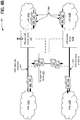
- Figure 2A illustrates an alternative exemplary architecture 200 in which embodiments may operate.
- Figure 2A depicts a first Wide Area Network (WAN) at element 205A, a second WAN 205B, a first Local Area Network (LAN) at element 210A, and a second LAN 210B.
- LAN access device 220A connects LAN 210A with WAN 205A through traffic aggregation unit 225.
- LAN 210B is connected with WAN 205B through LAN access device 220B.
- LAN access device 230 provides a communications interface between traffic aggregation unit 225 and LAN access device 220B.
- such an architecture 200 or system includes a first Local Area Network (LAN) access device 220A to establish a first LAN 210A and a second LAN access device 220B to establish a second LAN 210B which is operationally distinct from the first LAN 210A.
- the architecture 200 or system further includes a first Wide Area Network (WAN) backhaul connection 211 to provide the first LAN access device 220A with WAN connectivity.
- the architecture 200 or system further includes a second WAN backhaul connection 212 to provide the second LAN access device 210A with WAN connectivity.
- each of the first WAN backhaul connection 211 and the second WAN backhaul connection 212 are physically distinct.
- the architecture 200 or system of this embodiment further includes traffic aggregation unit 225 to form a logically bonded WAN interface 213 over the first WAN backhaul connection 211 and the second WAN backhaul connection 212.
- the logically bonded WAN interface 213 provides the first LAN access device 220A and the second LAN access device 220B with WAN connectivity via a combination of first bandwidth accessible via the first WAN backhaul connection 211 and second bandwidth accessible via the second WAN backhaul connection 212.
- the logically bonded WAN interface 213 provides the first LAN access device 220A with WAN connectivity and further provides the second LAN access device 220B with WAN connectivity.
- the logically bonded WAN interface 213 supplants (e.g., is used in place of, replaces, supersedes, etc.) the first WAN backhaul connection 211 for providing the first LAN access device 220A with its respective WAN connectivity and further supplants the second WAN backhaul connection 212 for providing the second LAN access device 220B with its respective WAN connectivity.
- both LAN access devices 220A-B communicate via logically bonded WAN interface 213 once established, rather than their respective WAN interfaces 211 and 212 respectively.
- the first WAN backhaul connection 211 provides the first LAN access device 220A with WAN connectivity via the first WAN backhaul connection 211 to a Service Provider that provides one or more of data connectivity, voice connectivity, video connectivity, and mobile device connectivity to a plurality of subscribers.
- the second WAN backhaul connection 212 provides the second LAN access device 220B with WAN connectivity via the second WAN backhaul connection 212 to the same Service Provider via a physically distinct communications link to the same Service Provider.
- WAN backhaul connections 211 and 212 may represent physically distinct communications links, yet both communicably link to the same service provider.
- Such a service provider may implement or establish the Wide Area Networks 205A-B.
- the physically distinct communications link to the same Service Provider associated with the second WAN backhaul connection is identified by an Internet Protocol (IP) address distinct from an IP address for the first WAN backhaul connection.
- IP Internet Protocol
- the physically distinct communications link to the same Service Provider associated with the second WAN backhaul connection 212 is associated with a subscriber's account distinct from a subscriber's account associated with the first WAN backhaul connection 211.
- the first WAN backhaul connection 211 may lead to one house or office
- the second WAN backhaul connection 212 may lead to a separate and distinct house or office. Nevertheless, both may trace back to the same service provider.
- the first WAN backhaul connection 211 provides the first LAN access device 220A with WAN connectivity via the first WAN backhaul connection 211 to a first Service Provider that provides one or more of data connectivity, voice connectivity, video connectivity, and mobile device connectivity to a plurality of subscribers and the second WAN backhaul connection 212 provides the second LAN access device 220B with WAN connectivity via the second WAN backhaul connection 212 to a second Service Provider separate and distinct from the first Service Provider.
- each of the first and second WAN backhaul connections 211 and 212 may lead to completely different service providers.
- At least a portion of traffic originating from the first LAN 210A and at least a portion of traffic originating from the second LAN 210B traverses the logically bonded WAN interface 213.
- a first plurality of traffic packets originating from the first LAN 210A traverses the logically bonded WAN interface 213 via the first WAN backhaul 211 through the traffic aggregation unit 225;
- a second plurality of traffic packets originating from the first LAN 210A traverses the logically bonded WAN interface 213 via the second WAN backhaul 212 through the traffic aggregation unit 225;
- a third plurality of traffic packets originating from the second LAN 210B traverses the logically bonded WAN interface 213 via the first WAN backhaul 211 through the traffic aggregation unit 225;
- a fourth plurality of traffic packets originating from the second LAN 210B traverses the logically bonded WAN interface 213 via the second WAN backhaul 212 through the traffic aggregation unit 225.
- packets originating from either LAN 210A-B may traverse the logically bonded WAN interface 213 via either or both underlying WAN backhaul connection 211 and/or 212.
- LAN devices within either LAN 210A-B may operate wholly agnostic or unaware of which underlying backhaul connection is being utilized for any given packet, as the traffic aggregation unit 225 provides the necessary coordination for the plurality of packets sent to, or designated for, various locations accessible within the WANs 205A-B (e.g., such as packets which must be routed to a location over the Internet, etc.).
- the first LAN 210A includes a first plurality of interconnected LAN nodes 238.
- each of the first plurality of interconnected LAN nodes 238 are identifiable within the first LAN 210A by a private Internet Protocol (IP) address managed by the first LAN access device 220A.
- the second LAN 210B includes a second plurality of interconnected LAN nodes 239, in which each of the second plurality of interconnected LAN nodes 239 are identifiable within the second LAN 210B by a private IP address managed by the second LAN access device 220B.
- the first LAN access device 220A is identifiable via a first unique Public IP address assigned to the first LAN access device 220A and the second LAN access device 220B is identifiable via a second unique Public IP address assigned to the second LAN access device 220B.
- the LAN nodes 238 and 239 may associate with the LAN access devices 220A and 220B, respectively according to their respective selection criteria. For example, LAN nodes 238 and 239 might associate with the LAN access device with the highest received power as indicated for example by RSSI (Received Signal Strength Indication). Alternatively, nodes might associate with LAN access devices based on the bandwidth that the LAN access devices can service the respective LAN node with, after servicing existing nodes. The WAN backhaul capacity of a LAN access device might also be taken into account to make this choice or selection. Another selection criterion might be that a LAN node associates with the LAN access device servicing fewer existing nodes. In other cases, the security requirements to associate with a LAN access device might leave the node with only one LAN access device to associate with.
- RSSI Receiveived Signal Strength Indication
- each of the unique Public IP addresses may be assigned by an ISP or service provider which provides internet connectivity to the respective LAN access devices 220A-B.
- each of the first and second unique Public IP address are directly addressable via a public Internet.
- the private Internet Protocol (IP) addresses managed by the LAN access device 220A-B are not directly addressable via the Internet, but instead, must rely upon Network Address Translation (NAT) or some forwarding mechanism, for example, a forwarding mechanism provided by a modem, a router, etc.
- NAT Network Address Translation
- none of the first or second plurality of interconnected LAN nodes 238 and 239 are directly addressable via the public Internet as each of the first or second plurality of interconnected LAN nodes 238 and 239 require address translation to a corresponding private IP address associated with the respective one of the first or second plurality of interconnected LAN nodes 238 and 239 to receive traffic from the public Internet.
- the LAN access devices may be Internet facing, whereas the interconnected LAN nodes 238 and 239 are not, and are thus protected to some extent as traffic must first traverse at least the LAN access device before any of the plurality of interconnected LAN nodes 238 and 239 can be accessed.
- the first LAN 210A includes a first plurality of interconnected LAN nodes 238, each of which are identifiable within the first LAN 210A by one or more Virtual Local Area Network (VLAN) tags managed by the first LAN access device 220A and the second LAN 210B includes a second plurality of interconnected LAN nodes 239, each of which are identifiable within the second LAN 210B by a second one or more VLAN tags which are managed by the second LAN access device 220B.
- VLAN Virtual Local Area Network
- the first LAN access device 220A provides Voice over Internet Protocol (VoIP) services and/or Internet Protocol Television (IPTV) services to one or more of the interconnected LAN nodes 238 within the first LAN 220A based on Ethernet level addressing using the one or more VLAN tags and the second LAN access device 220B provides VoIP services and/or IPTV services to one or more of the interconnected LAN nodes 239 within the second LAN 210B based on Ethernet level addressing using the second one or more VLAN tags.
- VoIP Voice over Internet Protocol
- IPTV Internet Protocol Television
- the second LAN access device 220B provides VoIP services and/or IPTV services to one or more of the interconnected LAN nodes 239 within the second LAN 210B based on Ethernet level addressing using the second one or more VLAN tags.
- any of the first and second plurality of interconnected LAN nodes 238 and 239 may be uniquely identifiable based at least on the one or more VLAN tags respectively managed by the first or second LAN access device 220A-B.
- the traffic aggregation unit 225 includes or is allocated or assigned a Public Internet Protocol (IP) address distinct from a public IP address associated with the first LAN access device 220A and distinct from a public IP address associated with the second LAN access device 220B.
- IP Internet Protocol
- the first WAN backhaul connection 211 includes or corresponds to a first transfer rate with the first LAN 210A and the second WAN backhaul connection 212 includes or corresponds to a second average transfer rate with the second LAN 210B.
- the bonded WAN interface 213 includes or corresponds to an aggregate transfer rate with the first LAN 210A and with the second LAN 210B which is greater than the first transfer rate and is greater than the second transfer rate of the first and second WAN backhaul connections 211 and 212 respectively.
- a client device within one of the LANs 210A-B may attain greater transfer rates using the logically bonded WAN interface 213 than would be possible using only one of the underlying first or second WAN backhaul connections 211 and 212.
- the first and second transfer rates may constitute one of an instantaneous data rate, an average peak data rate, or a peak transfer rate, and further in which the aggregate transfer rate results in data throughput capability which is greater than either of the first or the second respective transfer rates individually.
- the traffic aggregation unit 225 operates physically separate and distinct from each of the first LAN access device 220A and the second LAN access device 220B.
- the traffic aggregation unit 225 is communicatively interfaced between the first LAN access device 220A and the first WAN backhaul connection 211, in which the traffic aggregation unit has a direct communications link to each of the first LAN access device 220A and the first WAN backhaul connection 211.
- the traffic aggregation unit 225 is further communicatively interfaced with the second LAN access device 220B, in which the traffic aggregation unit 225 has an indirect communications link to the second WAN backhaul connection 212 through the second LAN access device 220B which operates in direct communication with the second WAN backhaul connection 212.
- the direct communications link communicably interfacing the traffic aggregation unit 225 between the first LAN access device 220A and the first WAN backhaul connection 211 may constitute a communications link with no other intermediate nodes, whereas the indirect communication link to the second WAN backhaul connection 212 includes at least one intermediate node before the indirect connection reaches the second WAN backhaul connection 212.
- LAN access device 230 is an intermediate node.
- LAN access device 220B may also serve as an intermediate node as the depicted route traverses the second LAN access device 220B to reach the second WAN backhaul connection 212.
- the system or architecture 200 further includes a third LAN access device 230 which is communicatively interfaced between the traffic aggregation unit 225 and the second LAN access device 220B.
- the third LAN access device 230 has a direct communications link to each of the traffic aggregation unit 225 and the second LAN access device 220B.
- the traffic aggregation unit 225 has an indirect communications link to the second LAN access device 220B through the third LAN access device 230, in which the third LAN access device 230 provides an alternate backup communications path to the logically bonded WAN interface 213 over the first WAN backhaul connection 211 and the second WAN backhaul connection 212 responsive to a failure event at one of the first LAN access device 220A or the second LAN access device 220B.
- Figure 2B illustrates an alternative exemplary architecture 201 in which embodiments may operate.
- Figure 2B additionally introduces traffic de-aggregator unit 235.
- such an architecture 201 or system further includes a traffic de-aggregator unit 235 communicatively interfaced between the first WAN backhaul connection 211 and the second WAN backhaul connection 212.
- the traffic aggregation unit 225 (forming the logically bonded WAN interface 213) bonds Internet Protocol (IP) addresses associated with traffic originating from both the first LAN 210A and the second LAN 210B.
- IP Internet Protocol
- the traffic aggregation unit 225 further routes the traffic having the bonded IP addresses through the traffic de-aggregator unit 235.
- the traffic de-aggregator unit 235 is managed by a Service Provider that provides one or more of data connectivity, voice connectivity, video connectivity, and mobile device connectivity to a plurality of subscribers via the first and second WAN backhaul connections 211 and 212.
- the traffic de-aggregator unit 235 operates physically separate and distinct from each of the first LAN access device 220A, the second LAN access device 220B, the third LAN access device 230, and the traffic aggregation unit 225.
- Figure 2C illustrates an alternative exemplary architecture 202 in which embodiments may operate.
- Figure 2C introduces the traffic aggregation unit 225 as an integrated sub-component of a LAN access device 220A.
- the traffic aggregation unit 225 operates as an integrated sub-component of the first LAN access device 220A, in which the first LAN access device 220A operates physically separate and distinct from the second LAN access device 220B.
- the traffic aggregation unit 225 is communicatively interfaced with the first WAN backhaul connection 211 via a communications interface of the first LAN access device 220A (e.g., internal circuitry of 220A, etc.).
- the traffic aggregation unit 225 is communicatively interfaced with the second LAN access device 220B, in which the traffic aggregation unit 225 uses an indirect communications link to the second WAN backhaul connection 212 through the second LAN access device 220B which operates in direct communication with the second WAN backhaul connection 212.
- Figure 2D illustrates an alternative exemplary architecture 203 in which embodiments may operate.
- Figure 2D introduces the traffic aggregation unit 225 as an integrated sub-component of a LAN access device 220A in communication with a traffic de-aggregator unit 235.
- the described architecture 203 or system includes a traffic de-aggregator unit 235 which is communicatively interfaced between the first WAN backhaul connection 211 and the second WAN backhaul connection 212, in which the traffic aggregation unit 225 forms a logically bonded WAN interface 213 over the first WAN backhaul 211 and the second WAN backhaul 212 by bonding Internet Protocol (IP) addresses associated with traffic originating from the first LAN 210A and the second LAN 210B and by further routing the traffic having the bonded IP addresses through the traffic de-aggregator unit 235.
- IP Internet Protocol
- the first WAN 205A and the second WAN 205B and the corresponding first WAN backhaul connection 211 and second WAN backhaul connection 212 form an aggregation network via the traffic de-aggregator 235, the traffic de-aggregator 235 being connected with Internet WAN 299 as shown.
- Figure 2E illustrates an alternative exemplary architecture 204 in which embodiments may operate.
- Figure 2E introduces LAN devices 240 having one or more wireless transceiver 241 (e.g., each with one or more antennas) to establish one or more wireless communication paths 242A and 242B.
- Wireless coverage areas 243 are further depicted as are wireless transceivers 244A and 244B at the LAN access devices 220A-B.
- At least one of a plurality of LAN devices 240 operating within the first LAN 210A use a first communication path to the first WAN backhaul connection 211 through the first LAN access device 220A and in such an embodiment, at least one of a plurality of LAN devices 240 operating within the first LAN 210A also use a second communication path to the second WAN backhaul connection 212 through the second LAN access device 220B.
- At least one LAN device 240 includes at least one of: a multiplexing wireless transceiver 241 capable to simultaneously maintain a first wireless communication path 242A to the first LAN access device 220A and a second wireless communication path 242B to the second LAN access device 220B by multiplexing between the first and second wireless communication paths 242A-B respectively; a wireless transceiver 241 capable to establish the first wireless communication path 242A to the first LAN access device 220A and capable to establish the wireless second communication path 242B to the second LAN access device 220B by terminating the first wireless communication path 242A and switching to the second wireless communication path 242B; and a first wireless transceiver 241 and a second wireless transceiver 241, the first and second wireless transceivers 241 capable to establish the first wireless communication path 242A to the first LAN access device 220A and capable to establish the wireless second communication path 242B to the second LAN access device 220B either concurrently or not concurrently with the first wireless
- the first LAN access 220A device is within a residential premises common to the at least one of a plurality of LAN devices 240 operating within the first LAN 210A and the second LAN access device 220B is within a second residential premises in a neighboring vicinity to the first residential premises.
- a wireless coverage area 243 associated with the second LAN access device 220B overlaps with the first residential premises and the at least one of a plurality of LAN devices 240 operating within the first LAN 210A.
- the at least one of a plurality of LAN devices 240 operating within the first LAN 210A establishes connectivity with the second WAN backhaul connection 212 through the second LAN access device 220B responsive to a failure event associated with the first LAN access device 220A.
- At least one of a plurality of LAN devices 240 operating within the first LAN 210A responsive to a failure event associated with the first LAN access device 220A, establishes connectivity to the second WAN backhaul connection 212 via a wireless connection path 242B between an transceiver 241 of the at least one of the plurality of LAN devices 240 within the first plurality of LAN devices 240 and an transceiver 244B of the second LAN access device 220B which is external to, and operationally distinct from, the first LAN access device 220A.
- the failure event corresponds to a hard failure event characterized by a total loss of connectivity between the first LAN access device 220A and the corresponding first WAN backhaul connection 211 or a soft failure event characterized by degraded connectivity, based on a threshold, between the first LAN access device 220A and the corresponding first WAN backhaul connection 211.
- the wireless connection between the transceiver 241 of at least one of the plurality of LAN devices 240 within the first LAN 210A and the transceiver 244B of the second LAN access device 220B constitutes at least one of the plurality of LAN devices 240 connecting with the second LAN access device 220B using a guest SSID (Service Set Identification) on the second LAN access device 220B.
- the guest SSID on the second LAN access device 220B enables guest devices (e.g., such as one of LAN devices 240 from the distinct LAN 210A) to communicate with the second WAN backhaul connection 212 through the second LAN access device 220B.
- the guest SSID on the second LAN access device 220B further restricts the guest devices from communicating with any devices operating within the second LAN 210B without first traversing the second WAN backhaul connection 212.
- the guest devices must nevertheless communicate through the WAN 205A-B, for example, by establishing communication via the Internet, as if the guest devices were still connected to their originating LAN access device 220A. In so doing, security can be maintained for the secondary network infrastructure while allowing the guest devices to utilize the second WAN backhaul 212 resource.
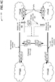
- Figure 2F illustrates an alternative exemplary architecture 206 in which embodiments may operate.
- Figure 2F introduces a traffic aggregation unit 225 as an integrated sub-component within one of a plurality of LAN devices 240A.
- the traffic aggregation unit 225 operates as an integrated sub-component within one of a plurality of LAN devices 240A operating within the first LAN 210A.
- the traffic aggregation unit 225 is communicatively interfaced with the first WAN backhaul connection 211 via a communications path to the first LAN access device 220A which in turn is interfaced via a communications path to the first WAN backhaul connection 211.
- the traffic aggregation unit 225 integrated as a sub-component within the one of the plurality of LAN devices 240A operating within the first LAN 210A, further is communicatively interfaced with the second LAN access device 220B, in which the traffic aggregation unit 225 uses an indirect communications link to the second WAN backhaul connection 212 through the second LAN access device 220B which operates in direct communication with the second WAN backhaul connection 212.
- the traffic aggregation unit 225 communicates with the first LAN access device 220A through a wireless communication path 242A from the one of the plurality of LAN devices 240A to the first LAN access device 220A and further wherein the traffic aggregation unit 225 communicates with the second LAN access device 220B through a second wireless communication path 242B from the one of the plurality of LAN devices 240A to the second LAN access device 220B.
- the first and second wireless communication paths 242A-B from the one of the plurality of LAN devices 240A to the first and second LAN access devices 220A-B respectively include at least one of: wireless connectivity via a multiplexing wireless transceiver 241 that simultaneously maintains the first wireless communication path 242A to the first LAN access device 220A and the second wireless communication path 242B to the second LAN access device 220B by multiplexing between the first and second wireless communication paths 242A-B respectively; wireless connectivity via a wireless transceiver 241 capable to establish the first wireless communication path 242A to the first LAN access device 220A and capable to establish the wireless second communication path 242B to the second LAN access device 220B by terminating the first wireless communication path 242A and switching to the second wireless communication path 242A; and wireless connectivity via a first wireless transceiver 241 and a second wireless transceiver 241, the first and second wireless transceivers 241 capable to establish the first wireless communication path 242A to the first
- Figure 2G illustrates an alternative exemplary architecture 207 in which embodiments may operate.
- Figure 2G re-introduces the traffic de-aggregator unit 235.
- the architecture 207 or system further includes a traffic de-aggregator unit 235 communicatively interfaced between the first WAN backhaul connection 211 and the second WAN backhaul connection 212, in which the traffic aggregation unit 225 (which is integrated as a sub-component of one of the LAN devices 240A) forms a logically bonded WAN interface 213 over the first WAN backhaul connection 211 and the second WAN backhaul connection 212 by bonding Internet Protocol (IP) addresses associated with traffic originating from both the first LAN 210A and the second LAN 210B and further by routing the traffic having the bonded IP addresses through the traffic de-aggregator unit 235.
- IP Internet Protocol
- the traffic de-aggregator may be managed by a Service Provider that provides one or more of data connectivity, voice connectivity, video connectivity, and mobile device connectivity to a plurality of subscribers via the first and second WAN backhaul connections.
- the traffic de-aggregator unit 235 may be physically separate and distinct from each of the first LAN access device 220A, the second LAN access device 220B, a third LAN access device 230 (if one is present), and the traffic aggregation unit 225.
- each of the first WAN backhaul connection 211 and the second WAN backhaul connection 212 are selected from the group of WAN backhaul connections which includes: a broadband connection; a Digital Subscriber Line (DSL) connection; a cable connection; a femtocell connection; a mobile connection; a fiber connection; a wireless connection; and an access Broadband over Power Line (BPL) connection.
- DSL Digital Subscriber Line
- BPL Broadband over Power Line
- each of the first and second LANs 210A and 210B include at least a user device.
- each of the first and second LAN access devices 220A-B communicably link each of the respective user devices with one of the first WAN backhaul connection 211 or the second WAN backhaul connection 212.
- any one of the interconnected LAN nodes 238 and 239 or the LAN devices 240 from Figure 2E , 240A and 240B may be a user device.
- each of the first LAN 210A and the second LAN 210B include a plurality of interconnected LAN nodes 238 and 239.
- each of the plurality of interconnected LAN nodes 238 and 239 communicate via at least one of: an Ethernet based network connection; a wireless based network connection; an Institute of Electrical and Electronics Engineers (IEEE) 802.11 standards based network connection; an 802.11a, 802.11b, 802.11g, and/or 802.11n wireless compatible network connection; a femto network connection transmitting via a mobile cellular compatible protocol including at least one of a third generation (3G) compatible protocol, a fourth generation (4G) compatible protocol, and a Long Term Evolution (LTE) compatible protocol; a power line connection; a telephone system connection; a Plain Old Telephone Service (POTS) connection; a G.hn (ITU-T standardized unified high-speed wire-line based home networking) connection; and a Coa
- each of the first LAN access device 220A and the second LAN access device 220B are selected from the group of access devices which includes: a base station; an access point; a modem; a router; a gateway; a Digital Subscriber Line (DSL) Customer Premises Equipment (CPE) modem; an in-home power line device; a Home Phoneline Network Alliance (HPNA) based device; an in-home coax distribution device; a G.hn compatible device; an in-home metering communication device; an in-home appliance communicatively interfaced with the LAN; a wireless femtocell base station; a wireless compatible base station; a wireless mobile device repeater; a wireless mobile device base station; a set-top box (STB)/set-top unit (STU) customer electronics device; an Internet Protocol (IP) enabled television; an IP enabled media player; an IP enabled gaming console; an Ethernet gateway; a computing device connected to the LAN; a HomePlug device
- DSL Digital Subscriber Line
- Figure 2H illustrates an alternative exemplary architecture 208 in which embodiments may operate.
- Figure 2H introduces a traffic aggregation unit 225 as an integrated sub-component within one a third LAN access device 230.
- the architecture 208 or system further includes a third LAN access device 230 which is communicably interfaced between the first LAN access device 220A and the second LAN access device 220B.
- the traffic aggregation unit 225 operates as an integrated sub-component of the third LAN access device 230, in which the third LAN access device 230 operates physically separate and distinct from each of the first LAN access device 220A and the second LAN access device 220B.
- the traffic aggregation unit uses a first connection, via a device communicably interfaced with the second LAN access device 220B and uses a second connection to communicably interface the traffic aggregation unit 225 with the first WAN backhaul connection 211.
- a data aggregation unit 231 combines traffic from the first connection and traffic from the second connection into aggregated traffic.
- a data de-aggregation unit 236 is communicably interfaced with the first WAN backhaul connection 211 and communicably interfaced with the second WAN backhaul connection 212.
- the data de-aggregation unit 236 de-aggregates traffic onto the first connection and onto the second connection as de-aggregated traffic.
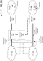
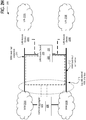
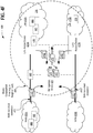
- FIG. 3A illustrates an alternative exemplary architecture 300 in which embodiments may operate. Depicted are a first Wide Area Network (WAN) at element 305A and a second WAN at 305B. WAN 305A being connected with Local Area Network (LAN) 310A via WAN backhaul connection 311 and WAN 305B being connected with LAN 310B via WAN backhaul connection 312.
- WAN Wide Area Network
- LAN Local Area Network
- such an architecture 300 or system includes a first Local Area Network (LAN) access device 320A to establish a first LAN 310A and a second LAN access device 320B to establish a second LAN 310B which is operationally distinct from the first LAN 310A.
- a first Wide Area Network (WAN) backhaul connection 311 provides the first LAN access device 320A with WAN connectivity and a second WAN backhaul connection 312 provides the second LAN access device 320B with WAN connectivity, in which each of the first WAN backhaul connection 311 and the second WAN backhaul connection 312 are physically distinct.
- WAN Wide Area Network
- This embodiment further includes a management device 325 communicatively interfaced with each of the first LAN access device 310A, the second LAN access device 310B, the first WAN backhaul connection 311, and the second WAN backhaul connection 312.
- the management device 325 responsive to a failure event, re-routes traffic associated with the first LAN 310A onto the second WAN backhaul connection 312 or re-routes traffic associated with the second LAN 310B onto the first WAN backhaul connection 311.
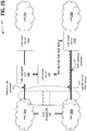
- Figure 3B illustrates an alternative exemplary architecture 301 in which embodiments may operate.
- the management device 325 is implemented within the first LAN access device 320A and communicatively interfaced with the LAN access device 320A via an internal communications bus of the first LAN access device (e.g., via internal circuitry).
- the management device 325 is communicatively interfaced with each of the second LAN access device 320B, the first WAN backhaul connection 311, and the second WAN backhaul connection 312 via one or more communication paths 350 external to the first LAN access device 320A.
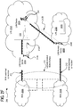
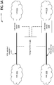
- FIG. 3C illustrates an alternative exemplary architecture 302 in which embodiments may operate.
- the management device 325 is implemented within a WAN access device 335A communicatively coupled with the first WAN backhaul connection 311 via an internal communications bus of the first WAN access device (e.g., via internal circuitry).
- the management device 325 is communicatively interfaced with each of the first LAN access device 320A, the second LAN access device 320B, and the second WAN backhaul connection 312 via one or more communication paths 350 external to the first WAN access device 335A.
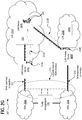
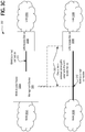
- FIG. 3D illustrates an alternative exemplary architecture 303 in which embodiments may operate.
- the management device 325 is implemented as an externally separate and physically distinct device from a first WAN access device 335A communicatively coupled with the first WAN backhaul connection 311, as an externally separate and physically distinct device from a second WAN access device 335B communicatively coupled with the second WAN backhaul connection 312, as an externally separate and physically distinct device from the first LAN access device 320A, and as an externally separate and physically distinct device from the second LAN access device 320B.
- the management device 325 is communicatively interfaced with each of the first WAN access device 335A, the second WAN access device 335B, the first LAN access device 320A, and the second LAN access device 320B, via one or more communication paths 350 external to the externally separate and physically distinct implementation of the management device 325.
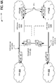
- FIG. 3E illustrates an alternative exemplary architecture 304 in which embodiments may operate.
- such an architecture 304 or system further includes a traffic aggregation unit 345 which operates externally separate and physically distinct from each of the first LAN access device 320A and the second LAN access device 320B.
- the traffic aggregation unit 345 forms a logically bonded WAN interface 313 over the first WAN backhaul 311 and the second WAN backhaul 312.
- the management device 325 is implemented within the traffic aggregation unit 345 and is communicatively interfaced with each of the first LAN access device 320A, the second LAN access device 320B, the first WAN backhaul connection 311, and the second WAN backhaul connection 312 via one or more communication paths 350 external to the traffic aggregation unit 345.
- the traffic aggregation unit 345 or the management device 325 operates in accordance with Synchronous optical networking (SONET) or synchronous digital hierarchy (SDH) multiplexing protocols.
- SONET Synchronous optical networking
- SDH synchronous digital hierarchy
- the traffic aggregation unit 345 or the management device 325 responsive to a failure event, re-routes the traffic by performing a SONET or SDH compatible rapid re-route function.
- the traffic aggregation unit 345 or the management device 325 responsive to a failure event, re-routes the traffic via an Ethernet Resilient Packet Ring (RPR) implementation.
- RPR Ethernet Resilient Packet Ring
- the management device 345 responsive to a failure event, re-routes the traffic by instituting one or more of the following events: (a) performing a first traffic re-route operation responsive to a hard failure event characterized by a total loss of connectivity for one of the first LAN access device 320A and the second LAN access device 320B with the corresponding first or second WAN backhaul connection 311 or 312; or (b) performing a second traffic re-route operation responsive to a soft failure event characterized by degraded connectivity as determined by a threshold for one of the first LAN access device 320A and the second LAN access device 320B with the corresponding first or second WAN backhaul connection 311 or 312.
- the first traffic re-route operation may be different than the second traffic re-route operation.
- FIG. 4A illustrates an alternative exemplary architecture 400 in which embodiments may operate. Depicted are a first Wide Area Network (WAN) at element 405A and a second WAN at 405B. WAN 405A being connected with Local Area Network (LAN) 410A via WAN backhaul connection 411 and WAN 405B being connected with LAN 410B via WAN backhaul connection 412.
- WAN Wide Area Network
- LAN Local Area Network
- such an architecture 400 or system includes a first Local Area Network (LAN) access device 420A to establish a first LAN 410A and a second LAN access device 420B to establish a second LAN 410B operationally distinct from the first LAN 410A.
- LAN Local Area Network
- a first Wide Area Network (WAN) backhaul connection 411 provides the first LAN access device 420A with WAN connectivity
- WAN backhaul connection 412 provides the second LAN access device 420B with WAN connectivity, in which each of the first WAN backhaul connection 411 and the second WAN backhaul connection 412 are physically distinct.
- a management device 425 is communicatively interfaced with each of the first LAN access device 420A, the second LAN access device 420B, the first WAN backhaul connection 411, and the second WAN backhaul connection 412.
- the management device 425 routes a first portion 498 of traffic originating from the first LAN 410A over the first WAN backhaul connection 411 and the management device 425 further routes a second portion 499 of the traffic originating from the first LAN 410A over the second WAN backhaul connection 412.
- the management device 425 routes the first portion 498 of traffic over the first WAN backhaul connection 411 and further routes the second portion 499 of the traffic over the second WAN backhaul connection 412 to implement load-balancing for the first LAN 410A.
- the management device 425 implements load balancing for the second LAN 410B by routing a first portion 444 of traffic originating from the second LAN 410B over the second WAN backhaul connection 412 and by further routing a second portion 445 of the traffic originating from the second LAN 410B over the first WAN backhaul connection 411.
- Management device 425 may implement load balancing for the respective first and/or second LANs regardless of whether the management device is internal to LAN access device 420A or 420B.
- the management device 425 implementing load balancing includes determining what portions of traffic 498 and 499 to route over the first and second WAN backhauls, respectively, based on factors such as bandwidth capacity of the first and second WAN backhauls, or based on other factors such as payment options chosen by the first and second subscribers, or conditions imposed by their internet service providers, based on a number of nodes associated with each of the LAN access devices, based on traffic patterns of each of the nodes, the security options, or the capacity and capabilities of the LAN access devices etc. These factors, among others, will cause the management device 425 to vary the portion of traffic to route across the first and second WAN backhauls.
- traffic portion 498 includes control and management traffic and traffic portion 499 includes the payload portion of traffic corresponding to traffic portion 498.
- the management device 425 implements load balancing for the first LAN 410A by routing the first portion 498 of traffic over the first WAN backhaul connection 411 and further routes the second portion 499 of the traffic over the second WAN backhaul connection 412. Separating or splitting the payload and control traffic portions in such a way reduces the overhead caused due to the control and management traffic. For example, when an IEEE 802.11n LAN access device is operating in the presence of a legacy station operating on IEEE 802.11b, there will be substantial overhead due to control frames such as RTS/CTS and ACK. In such an event, routing all the control traffic over the second WAN backhaul can help reduce overhead and improve throughput.
- first LAN access device is a wireless LAN access device 421 having a first transfer rate for the first LAN 410A which is greater than a second transfer rate for the first WAN backhaul connection 411, in which the second transfer rate for the first WAN backhaul connection 411 results (e.g., causes) a bottleneck to the traffic (e.g., the first and second portions 498 and 499) originating from the wireless LAN access device 421 directed to the first WAN backhaul connection 411.
- the traffic e.g., the first and second portions 498 and 49
- the management device 425 implements load-balancing for the first LAN 410A by routing the first portion 498 of traffic over the first WAN backhaul connection 411 at a rate which is less than the second transfer rate for the first WAN backhaul connection 411 and further by routing the second portion of the traffic 499 over the second WAN backhaul connection 412, in which the second portion 499 of the traffic is a remaining portion of the traffic originating from the first LAN 410A.
- the management device 425 implements load-balancing for the first LAN 410A by implementing an aggregate transfer rate for WAN connectivity provided to the first LAN 410A by the wireless LAN access device 421 and by implementing an aggregate transfer rate for WAN connectivity provided to the second LAN 410B, in which the aggregate transfer rate for WAN connectivity is greater than the second transfer rate for the first WAN backhaul connection 411.
- an aggregate transfer rate for WAN connectivity can be realized for the LANs 410A-B which is greater than they would otherwise attain from using only their respective single WAN backhaul connections (e.g., either 411 or 412, but not both).
- the management device 425 implements load-balancing for the first LAN 410A by assigning incoming flows to the most lightly-loaded WAN connection. For example, the management device 425 may assign, route, or otherwise place a new incoming flow, such as a new VoIP connection or Internet TV stream, onto the most lightly-loaded WAN connection.
- the management device 425 routes the first portion 498 of traffic over the first WAN backhaul connection 411 and further routes the second portion 499 of the traffic over the second WAN backhaul connection 412 by allocating a portion of bandwidth associated with the second WAN backhaul connection 412 to the first LAN access device (e.g., 420A from Figure 4A or the wireless LAN access device 421 of Figure 4B ), in which the allocation is based on a paid subscription tier or a service level tier associated with the first LAN access device (420A or 421).
- the paid subscription tier or a service level tier may be chosen by a user when signing up for service from a service provider.
- a user may elect to pay an increased subscription fee to enable a higher aggregate transfer rate than is otherwise attainable from using only a single WAN backhaul connection 411 or 412.
- a user might obtain a subsidized subscription fee to allow other users access to his unused WAN bandwidth.
- FIG. 4C illustrates an alternative exemplary architecture 402 in which embodiments may operate.
- the architecture 402 or system further includes a wireless communications link 422 between the first LAN access device operating as a wireless LAN access device 421 and the second LAN access device operating as a second wireless LAN access device 423.
- the management device 425 instructs the wireless LAN access device 421 to route or switch the second portion of traffic 499 over the wireless communications link 422 from the first wireless LAN access device 421 to the second wireless LAN access device 423 and onto the second WAN backhaul connection 412.
- the second LAN access device 423 can operate as a wireless LAN access device, distinct from the first wireless LAN access device 421.
- the communication link 422 may be a wireless communication link between the first LAN access device operating as a wireless LAN access device 421 and the second LAN access device operating as a second wireless LAN access device 423.
- the first WAN backhaul connection 411 provides the first LAN access device (e.g., 420A at Figure 4A or 421 at Figure 4C ) with WAN connectivity via the first WAN backhaul connection 411 to a Service Provider that provides one or more of data connectivity, voice connectivity, video connectivity, and mobile device connectivity to a plurality of subscribers.
- the second WAN backhaul connection 412 provides the second LAN access device (e.g., 420B at Figure 4A or 423 at Figure 4C ) with WAN connectivity via the second WAN backhaul connection 412 to the same Service Provider via a physically distinct communications link to the same Service Provider.
- the first WAN backhaul connection 411 provides the first LAN access device (420A or 421) with WAN connectivity via the first WAN backhaul connection 411 to a first Service Provider that provides one or more of data connectivity, voice connectivity, video connectivity, and mobile device connectivity to a plurality of subscribers and in this embodiment, the second WAN backhaul connection 412 provides the second LAN access device (420B or 423) with WAN connectivity via the second WAN backhaul connection 412 to a second Service Provider which is separate and distinct from the first Service Provider.
- Figure 4D illustrates an alternative exemplary architecture 403 in which embodiments may operate.
- the architecture 403 or system further includes the management device 425 collecting a first information set 470A about the first WAN backhaul connection 411; further includes the management device 425 collecting a second information set 470B about the first LAN 410A; further includes the management device 425 collecting a third information 470C set about the second WAN backhaul connection 412; and further includes the management device 425 collecting a fourth information set 470D about the second LAN 410B.
- the management device 425 jointly analyzes at least a portion from each of the first, second, third, and fourth information sets 470A-D collected and identifies an operational condition 471 affecting the first and second WAN backhaul connections 411-412 and further affecting the first and second LANs 410A-B based on the jointly analyzed collected information sets 470A-D. In accordance with such an embodiment, the management device 425 initiates a management event 472 responsive to the operational condition 471 being identified.
- the management device 425 initiating the management event 472 constitutes generating instructions specifying a configuration change to one or more of: a configuration change for a channel allocation associated with a wireless based first LAN access device 420A or a wireless based second LAN access device 420B, or both; a configuration change to a power allocation scheme for signals associated with the wireless based first LAN access device 420A or the wireless based second LAN access device 420B, or both; a configuration change to STA (Station) to AP (Access Point) associations associated with the wireless based first LAN access device 420A or the wireless based second LAN access device 420B, or both; a configuration change to beacon power characteristics associated with the wireless based first LAN access device 420A or the wireless based second LAN access device 420B, or both; a configuration change to beacon intervals associated with the wireless based first LAN access device 420A or the wireless based second LAN access device 420B, or both
- IEEE 802.11a/b/g/n configuration of the wireless based first LAN access device 420A or the wireless based second LAN access device 420B, or both; a configuration change to the bandwidth utilized by the wireless based first LAN access device 420A or the wireless based second LAN access device 420B, or both (example, channel bonding in IEEE 802.1 In); a configuration change to frame aggregation of traffic from the wireless based first LAN access device 420A or the wireless based second LAN access device 420B, or both; a configuration change to guard interval of the wireless based first LAN access device 420A or the wireless based second LAN access device 420B, or both; a configuration change to an antenna array configuration of the wireless based first LAN access device 420A or to the wireless based second LAN access device 420B, or both; a configuration change to preamble length used by the wireless based first LAN access device 420A or the wireless based second LAN access device 420B, or both; a
- the wireless based LAN access devices involved in this configuration may be chosen from a wider set of wireless based LAN access devices already available. Such LAN access devices may support high throughput. In one embodiment, selection of these LAN access devices is based on one or more of a Received Signal Strength Indicator (RSSI), a wireless bit rate, channel usage, pre-existing traffic loads, overall achievable throughput, other similar performance indicators, or by using a combination of such indicators to estimate available throughput.
- RSSI Received Signal Strength Indicator
- the management event 472 is selected from the group of management events 472 which includes sending instructions 478 to establish a direct communications link 476 between the first LAN access device 420A and the second LAN access device 420B responsive to the joint analysis indicating an operational problem (e.g., such as the identified operational condition 471) with the first WAN backhaul connection 411.
- an operational problem e.g., such as the identified operational condition 471
- the operational problem may be derived from or correspond to the identified operational condition 471.
- Figure 4E illustrates an alternative exemplary architecture 404 in which embodiments may operate.
- the management event 472 is selected from the group of management events 472 which includes sending instructions 478 to establish a direct communications link 476 between a node 477 operating within the first LAN 410A, and the second LAN access device 420B, responsive to the joint analysis indicating an operational problem with the first LAN access device 410A.
- the instructions 478 may correspond to or be derived from the management event 472.
- node 477 may be implemented as one of a wireless node, a mobile node, or as a LAN device node.
- the management device 425 jointly analyzes the collected information sets 470A-D by analyzing bandwidth usage over time of the first LAN 410A and bandwidth usage over time of the second LAN 410B and detects, as the operational condition 471, a traffic imbalance between the first LAN 410A and the second LAN 410B.
- initiating the management event 472 constitutes the management device 425 allocating unused bandwidth associated with the first WAN backhaul connection 411 to the second LAN access device 420A or constitutes allocating unused bandwidth associated with the second WAN backhaul connection 412 to the first LAN access device 420A based on the identified traffic imbalance between the first LAN 410A and the second LAN 410B.
- initiating the management event 472 constitutes the management device 425 determining whether a LAN access device has unused bandwidth at a given time of the day or week.
- multiple SSIDs may be used to open the unused bandwidth for public or private usage during the given time of the day or week or during some other specified time.
- the second information set 470B about the first LAN 410A and the fourth information set 470D about the second LAN 410B each include information specific to a first communication layer of the first and second LANs 410A-B and the first information set 470A about the first WAN backhaul connection 411 and the third information set 470C about the second WAN backhaul connection 412 includes information specific to a second communication layer of the first and second WAN backhaul connections 411-412 which is different than the first communication layer of the first and second LANs 410A-B.
- Figure 4F illustrates an alternative exemplary architecture 406 in which embodiments may operate.
- the second information set 470B about the first LAN 410A and the fourth information set 470D about the second LAN 410B each include neighborhood analysis relating to Internet connectivity provided to a plurality of other locations in a shared geographical area 469 with the management device 425.
- the management device 425 initiating the management event 472 responsive to the operational condition 471 being identified constitutes generating instructions 479 to change a configuration of the first WAN backhaul connection 411 or constitutes generating instructions 479 to change a configuration of the second WAN backhaul connection 412, or both, based on the neighborhood analysis.
- the first information set 470A about the first WAN 410A and the third information set 470C about the second WAN 410B each include neighborhood analysis relating to Internet connectivity provided to a plurality of other locations in a shared geographical area 469 with the management device and the management device 425 initiating the management event 472 responsive to the operational condition being identified 471 constitutes the management device 425 generating instructions 479 to change a configuration of the first LAN access device 420A or the second LAN access device 420B, or both, based on the neighborhood analysis.
- the management device 425 initiating the management event 472 responsive to the operational condition being identified 471 constitutes the management device 425 generating instructions 479 to modify the identified operational condition 471 in which the management device 425 communicates the generated instructions 479 to one or more of: a network element 466, a WAN device 468, and/or a LAN device 467 communicatively interfaced with the management device and further in which the generated instructions 479 are communicated via a protocol selected from the group of protocols which includes: a TR-069 (Technical Report 069) compatible communications protocol; a Transmission Control Protocol/Internet Protocol (TCP/IP) communications protocol; a Simple Network Management Protocol (SNMP) communications protocol; an out-of-band telephone line protocol; a Digital Subscriber Line Embedded Operations Channel (DSL EOC) communications protocol; a cable control channel communications protocol; a power line control channel communications protocol; a Command Line Interface (CLI) protocol; and a Transaction Language 1 (TL1) communications protocol.
- TR-069 Technical Report 069
- the first WAN backhaul connection 411 and the second WAN backhaul connection 412 are each communicably interfaced with the management device 425 via one of: a wireless network connection; a wired network connection; a Digital Subscriber Line (DSL) network connection; a power line network connection; a Passive Optical Network (PON) based network connection; a fiber optic based network connection; and a cable based network connection.
- DSL Digital Subscriber Line
- PON Passive Optical Network
- the management device 425 is one of: a Digital Subscriber Line (DSL) modem operating as a Customer Premises Equipment (CPE) device to communicatively interface a DSL based backhaul provided via the first WAN backhaul connection 411 to the first LAN 410A; a cable modem operating to communicatively interface a cable network based backhaul provided via the first WAN backhaul connection 411 to the first LAN 410A; a wireless modem operating to communicatively interface a wireless based backhaul provided via the first WAN backhaul connection 411 to the first LAN 410A; a power line modem operating to communicatively interface a power line based backhaul provided via the first WAN backhaul connection 411 to the first LAN 410A; an Optical Network Terminal (ONT) operating to communicatively interface a fiber optic based backhaul provided via the first WAN backhaul connection 411 to the first LAN 410A; a router operating to communicatively interface
- the management device 425 collecting the first, second, third, and fourth information sets 470A-D constitutes the management device 425 collecting each of the information sets 470A-D from an information source selected from the group of information sources which includes: a Digital Subscriber Line (DSL) Customer Premises Equipment (CPE) modem; an in-home power line device; a Home Phoneline Network Alliance (HPNA) based device; an in-home coax distribution device; a G.hn compatible device; an in-home metering communication device; an in-home appliance communicatively interfaced with the LAN; a wireless femtocell base station; a wireless compatible base station; a wireless mobile device repeater; a wireless mobile device base station; a set-top box (STB)/set-top unit (STU) customer electronics device; an Internet Protocol (IP) enabled television; an IP enabled media player; an IP enabled gaming console; an Ethernet gateway; a computing device connected to the LAN; an Ethernet connected computer peripheral device; an Ethernet
- DSL Digital Subscriber Line
- the first WAN backhaul connection 411 and the second WAN backhaul connection 412 are selected from the group of WAN backhaul connections 411 and 412 which include: a broadband connection; a DSL connection; a cable connection; a femtocell connection; a mobile connection; a fiber connection; a wireless connection; and an access Broadband over Power Line (BPL) connection.
- BPL Broadband over Power Line
- each of the first LAN 410A and the second LAN 410B include a plurality of interconnected LAN nodes 238.
- each of the plurality of interconnected LAN nodes 238 communicate via at least one of: an Ethernet based network connection; a wireless based network connection; an Institute of Electrical and Electronics Engineers (IEEE) 802.11 standards based network connection; an 802.11a, 802.11b, 802.11g, 802.11ad at 60 GHz, and/or 802.11n wireless compatible network connection; a femto network connection transmitting via a mobile cellular compatible protocol including at least one of a third generation (3G) compatible protocol, a fourth generation (4G) compatible protocol, and a Long Term Evolution (LTE) compatible protocol; a power line connection; a telephone system connection; a Plain Old Telephone Service (POTS) connection; a G.hn (ITU-T standardized unified high-speed wire-line based home networking) connection; and a Coax cable connection
- each of the first LAN access device 420A and the second LAN access device 420B are selected from the group of devices which includes: a base station; an access point; a modem; a router; a gateway; a Digital Subscriber Line (DSL) Customer Premises Equipment (CPE) modem; an in-home power line device; a Home Phoneline Network Alliance (HPNA) based device; an in-home coax distribution device; a G.hn compatible device; an in-home metering communication device; an in-home appliance communicatively interfaced with the LAN; a wireless femtocell base station; a wireless compatible base station; a wireless mobile device repeater; a wireless mobile device base station; a set-top box (STB)/set-top unit (STU) customer electronics device; an Internet Protocol (IP) enabled television; an IP enabled media player; an IP enabled gaming console; ; a 60 GHz capable station; PAN (Personal Area Networks) capable device; an Ethernet gateway; a
- IP
- each of the first LAN 410A and the second LAN 410B include a plurality of interconnected LAN nodes 238 and each of the plurality of interconnected LAN nodes 238 are selected from the group of nodes which includes: a computer with LAN connectivity; a notebook with LAN connectivity; a mobile phone with LAN connectivity; a game console with LAN connectivity; an electronic computing machine with LAN connectivity; an IPTV with LAN connectivity; storage devices with LAN connectivity; devices that are primarily purposed for other applications and can have LAN connectivity, for example, household lighting, alarm systems, heating/cooling and other household appliances, etc.
- FIG. 4G illustrates an alternative exemplary architecture 407 in which embodiments may operate.
- the management device 425 collects, for joint analysis, information from the LANs 410A, 410B, 410C, 410D, 410E, and 410F, including neighborhood analysis 440 relating to Internet connectivity provided to a plurality of locations in a neighborhood or a shared geographical area 469 with the management device 425.
- initiating a management event 472 includes a management device 425 generating instructions or commands to change a configuration of a WAN device based on the neighborhood analysis 440 collected.
- initiating a management event 472 includes a management device 425 generating instructions to change a configuration of a LAN device (e.g., one of nodes 477A-C) based on the neighborhood analysis 440.
- Joint analysis by the management device 425 may include conducting neighborhood analysis including aggregating information multiple sources to provide a broader analytical context.
- nodes 477A, 477B, and 477C are depicted as traversing a shared back-haul 414 to a WAN 405A.
- WAN 405A includes a management device 425 implemented as described herein. Because nodes 477A-C all traverse a common or shared back-haul 414, information may be retrievable from each of the nodes 477A-C and correspondingly from Local Area Networks 410A, 410B, and 410C respectively. The information may be collected by management device 425 within WAN 405A and utilized to optimize the WAN and LAN networks and the communication paths between the respective WAN and LAN networks.
- a shared back-haul 414 may exist with DSL networks in which multiple twisted pair lines traverse a common DSL binder; a shared back-haul 414 may be present with multiple coaxial cable internet customers each contending for WAN based resources over a single coaxial cable over which at least a portion of WAN back-haul is implemented; a shared back-haul 414 may be present with a power line based Internet service provider in which multiple LANs (e.g., 410A-C) associated with distinct end-users contend for WAN based resources over the same physical transmission lines; a shared back-haul 414 may similarly be present where multiple LANs (e.g., 410A-C) associated with distinct end-users contend for WAN based resources over the same wireless transmission spectrum; a shared back-haul 414 may be present with fiber optic based connections each contending for WAN based resources; or a shared back-haul 414 may comprise of a combination of the above communication means, such as a combination of
- a management device 425 may collect information from multiple distinct LANs and analyze the collected information from the multiple LANs to identify an operational condition 471. Such analysis may be referred to as neighborhood analysis. The management device 425 may then report, diagnose, monitor, or generate instructions to implement an operational change via a management event 472 based on the neighborhood analysis. For example, the management device 425 may implement WAN/LAN network optimizations which include increasing transmit power and data rates to one LAN (e.g., 410A) based on determination that another LAN represented within the neighborhood analysis is inactive or has a low activity rate (e.g., LAN 410C may be determined to be underutilized). In such an embodiment, a corresponding decrease of transmit power and data rate may be implemented for the underutilized LAN (e.g., 410C in such an example).
- WAN/LAN network optimizations which include increasing transmit power and data rates to one LAN (e.g., 410A) based on determination that another LAN represented within the neighborhood analysis is inactive or has a low
- neighborhood analysis may indicate that the shared back-haul 414 is saturated due to a demand load in excess of capacity based on analysis of LAN information retrieved from the multiple distinct LANs 410A-C in which case the management device 425 may responsively implement a load-balancing algorithm on a WAN/LAN interface (e.g., a DSL modem, cable modem, ONT unit, etc.) interfacing each of the respective LANs 410A-C to the single shared back-haul 414.
- a WAN/LAN interface e.g., a DSL modem, cable modem, ONT unit, etc.
- a collection module of a management device 425 collects the neighborhood analysis from a WAN operator (e.g., WAN 405B), where the neighborhood analysis describes LAN wireless transmission channels for a plurality of locations in a shared geographical area 469 with the management device. For example, within the neighborhood or shared geographical area 469 are multiple distinct LANs 410D, 410E, and 410F. Each of the distinct LANs 410D-F are transmitting information 440 to WAN 405B, such as an ISP or Wide Area Network Operator. The information 440 sent via each of the LANs may describe various characteristics about the LAN from which the information originated. In one embodiment, the WAN 405B aggregates the information 440 and makes the aggregate information available as neighborhood analysis. Each management device 425 within each of the respective LANs 410D-F may then collect and analyze the neighborhood analysis, and may additionally implement operational changes within a corresponding LAN 410D-F based on the information collected from the WAN 405B.
- a WAN operator e.g.
- instructions are generated by a management device 425 to change the configuration of a LAN device based on the neighborhood analysis.
- the generated instructions select a LAN wireless transmission channel for a LAN device communicatively interfaced with the management device 425 that minimizes wireless interference between the LAN device and a plurality of other locations in the neighborhood or shared geographical area 469 with the management device 425.
- each of the management devices within the various LANs 410D-F implement similar instructions, although, the management devices 425 within the respective LANs 410D-F need not have operational awareness of any other management device 425 as the neighborhood analysis is collected from WAN 405B.
- a management device within the WAN 405B or located elsewhere may initiate instructions to implement an operational change via a management event 472 within the WAN 405B or within multiple distinct LANs 410D-F.
- operational efficiency of the individual LANs 410A-F may be improved by reducing interference between closely located LANs, based on the neighborhood analysis.
- Such information may be correlated by a WAN operator based on, for example, mapping overlapping identifiers to a virtually rendered neighborhood or shared geographic area 469 or alternatively, based on actual knowledge of geographic locations for multiple LANs 410, for example, by cross referencing subscribers' service address information to physical locations.
- Diagnostics may similarly rely upon neighborhood analysis yielded from multiple distinct LANs 410.
- multiple LAN devices 410A-F exhibiting high error counts, or abnormal retrains/modem resets may be indicative of a fault within the WAN 405A-B infrastructure rather than a statistically less likely coincidence that multiple LAN side devices are each simultaneously exercising a similar fault.
- neighborhood analysis from multiple LANs 410A-F within a common geographical area or multiple LANs associated with a single shared back-haul 414 may aid in systematically diagnosing a LAN side fault within a particular end-user consumer's local area network where similar devices operating in neighboring LANs 410A-F do not present corresponding errors or faults within the neighborhood analysis.
- Figure 5A shows a diagrammatic representation of a system 500 in accordance with which embodiments may operate, be installed, integrated, or configured.
- system 500 includes a memory 595 and a processor or processors 596.
- memory 595 may store instructions to be executed and processor(s) 596 may execute such instructions.
- Processor(s) 596 may also implement or execute implementing logic 560 having logic to implement the methodologies discussed herein.
- System 500 includes communication bus(es) 515 to transfer transactions, instructions, requests, and data within system 500 among a plurality of peripheral devices communicably interfaced with one or more communication buses 515.
- system 500 includes a communication bus 515 to interface, transfer, transact, relay, and and/or communicate information, transactions, instructions, requests, and data within system 500, and among plurality of peripheral devices.
- System 500 further includes management interface 525, for example, to receive requests, return responses, and otherwise interface with network elements located separately from system 500.
- management interface 525 communicates information via an out-of-band connection separate from LAN and/or WAN based communications, where "in-band" communications are communications that traverse the same communication means as payload data (e.g., content) being exchanged between networked devices and where "out-of-band” communications are communications that traverse an isolated communication means, separate from the mechanism for communicating the payload data.
- An out-of-band connection may serve as a redundant or backup interface over which to communicate control data between the management device 501 (or one of 170, 325, or 425) and other networked devices or between the management device 501 and a third party service provider.
- System 500 further includes LAN interface 530 to communicate information via a LAN based connection, including collecting LAN information from within a LAN, reporting information and diagnostics to other entities within the LAN, and for initiating instructions and commands over the LAN.
- Information communicated via a LAN interface 530 may, in some embodiments, traverse the LAN to a LAN to WAN interface and continue to a destination within a connected WAN.
- System 500 further includes WAN interface 535 to communicate information via a WAN based connection, including collecting WAN information from within a WAN, reporting information and diagnostics to other entities within the WAN, and for initiating instructions and commands over the WAN.
- Information communicated via WAN interface 535 may, in some embodiments, traverse the WAN to a WAN to LAN interface and continue to a LAN based destination.
- System 500 further includes stored historical information 550 that may be analyzed or referenced when conducting long term trending analysis and reporting.
- System 500 may further include multiple management events 555, any of which may be initiated responsive to the identification of an operational condition. For example, corrective actions, additional diagnostics, information probes, configuration change requests, local commands, remote execution commands, and the like may be specified by and triggered as a management event 555.
- operational reports, configuration reports, network activity reports and diagnostic reports may be generated and sent in accordance with stored management events 555.
- the stored historical information 550 and the management events 555 may be stored upon a hard drive, persistent data store, a database, or other storage location within system 500.
- Management Device 501 Distinct within system 500 is Management Device 501 which includes collection module 570, analysis module 575, diagnostics module 580, and implementation module 585.
- Management Device 501 may be installed and configured in a compatible system 500 as is depicted by Figure 5A , or provided separately so as to operate in conjunction with appropriate implementing logic 560 or other software.
- collection module 570 collects information from available sources, such as LAN information and WAN information via interfaces of system 500, including one or more of management interface 525, LAN interface 530, and/or WAN interface 535.
- Analysis module 575 analyzes the information retrieved via collection module 570.
- LAN information and WAN information is jointly analyzed to identify an operational condition within the LAN based on collected WAN information or identify an operational condition within the WAN based on collected LAN information.
- Analysis module 575 may further perform long term trending analysis based on stored historical information 550 or conduct neighborhood analysis based on aggregation data yielded from multiple separate and distinct LANs, or conduct other joint analysis based on LAN information sets received and/or based on WAN backhaul connection information sets received.
- Diagnostics module 580 may conduct specialized diagnostic routines and algorithms in conjunction with or separately from analysis module 575. Diagnostics module 580 may conduct additional probing diagnostics to retrieve or trigger the output of additional diagnostics information for further analysis.
- Implementation module 585 implements and initiates various management events 555 including generating and instantiating instructions for local or remote execution, generating and transmitting configuration change requests, generating and sending operational reports, diagnostic reports, and configuration reports.
- Figure 5B shows a diagrammatic representation of a system 502 in accordance with which embodiments may operate, be installed, integrated, or configured. Depicted as before are a memory 595, processor(s), bus 515, a management interface 525 to communicate with system 502 including to communicate with sub-components 591 and 590 of system 502, LAN interface 530 capable to communicate with LANs and LAN devices, WAN interface 535 capable to communicate with WANs, WAN backhaul connections and WAN devices, and implementing logic 560.
- Traffic aggregation unit 591 and traffic de-aggregator 590 are separately depicted within system 502.
- Traffic aggregation unit 591 includes receiving unit 581 to receive data, packets, traffic, control signals and messages, and so forth.
- Traffic aggregation unit 591 includes backhaul bonding unit 582 to bond multiple distinct WAN backhaul connections into a single logical backhaul connection.
- Traffic aggregation unit 591 includes data aggregation unit 583 to collect and aggregate data, packets, traffic, and so forth associated with multiple distinct connections, such as distinct LAN connections, and place the incoming data, packets, traffic, etc., onto a logical bonded backhaul connection formed by the traffic aggregation unit 591.
- the data, packets, traffic, etc., once aggregated by data aggregation unit 583 are transmitted, forwarded, or routed forward via the transmitting unit 584.
- Traffic de-aggregator 590 includes receiving unit 591 to receive incoming data, packets, traffic, etc.
- incoming data, packets, control packets, traffic may originate from various sources within a WAN, such as from sources accessible via the Internet, and be destined for one of the LANs communicably interfaced with the traffic de-aggregator 590.
- Traffic de-aggregator 590 further includes data de-aggregation unit 593 to split, separate, divide up, de-aggregate incoming data, packets, traffic etc. which is received by receiving unit 591.
- data coming into the traffic de-aggregator 590 needs to be split up and placed onto different WAN backhaul connections for transmission back to an originating source or to a target source in accordance with the described embodiments.
- Traffic de-aggregator 590 further includes transmitting unit 594 to place de-aggregated data, packets, frames, etc., onto multiple WAN backhaul connections for transmission to a specified target as described above.
- Figures 6A , 6B , and 6C are flow diagrams 600A, 600B, and 600C respectively, illustrating methods for traffic aggregation; methods for traffic load balancing; and methods for self-healing in accordance with described embodiments.
- Methods 600A, 600B, and/or 600C may be performed by processing logic that may include hardware (e.g., circuitry, dedicated logic, programmable logic, microcode, etc.), software (e.g., instructions run on a processing device to perform various operations such as interfacing functions, collecting, monitoring, diagnosing and reporting information, and executing/initiating management events, commands and instructions responsive to analysis and diagnosis, or some combination thereof).
- processing logic may include hardware (e.g., circuitry, dedicated logic, programmable logic, microcode, etc.), software (e.g., instructions run on a processing device to perform various operations such as interfacing functions, collecting, monitoring, diagnosing and reporting information, and executing/initiating management events, commands and instructions responsive to analysis and diagnosis, or
- methods 600A, 600B, and 600C are performed or coordinated via a Management device such as that depicted at element 170 of Figure 1 or via a Management Device such as that depicted at element 501 of Figure 5A .
- a Management device such as that depicted at element 170 of Figure 1 or via a Management Device such as that depicted at element 501 of Figure 5A .
- Other embodiments utilize a traffic aggregation unit such as that set forth at element 225 beginning at Figure 2A and element 591 of Figure 5B .
- Still other embodiments utilize a traffic de-aggregator such as that set forth at element 235 beginning at Figure 2B and element 590 of Figure 5B .
- Some of the blocks and/or operations listed below are optional in accordance with certain embodiments. The numbering of the blocks presented is for the sake of clarity and is not intended to prescribe an order of operations in which the various blocks must occur. Additionally, operations from the various flows 600A, 600B, and 600C may be utilized in a variety of combinations.
- Method 600A begins with processing logic for establishing a first Local Area Network (LAN) via a first access device as set forth at block 602.
- processing logic establishes a second LAN via a second access device.
- LAN Local Area Network
- processing logic provides the first LAN access device with WAN connectivity via a first Wide Area Network (WAN) backhaul connection and at block 608, processing logic provides the second LAN access device with WAN connectivity via a second WAN backhaul connection.
- WAN Wide Area Network
- processing logic communicatively interfaces a traffic aggregation unit.
- processing logic forms a logically bonded WAN interface over the first WAN backhaul and the second WAN backhaul.
- processing logic combines traffic from different connections into aggregated traffic.
- processing logic communicatively interfaces a traffic de-aggregator.
- processing logic bonds Internet Protocol (IP) addresses associated with traffic originating from both the first LAN and the second LAN.
- IP Internet Protocol
- processing logic routes the traffic having the bonded IP addresses through the traffic de-aggregator.
- processing logic provides an alternate backup communications path to the logically bonded WAN interface responsive to a failure event.
- Method 600B begins with processing logic for establishing a first Local Area Network (LAN) via a first access device as set forth at block 640.
- processing logic establishes a second LAN via a second access device.
- LAN Local Area Network
- processing logic provides the first LAN access device with WAN connectivity via a first Wide Area Network (WAN) backhaul connection and at block 646, processing logic provides the second LAN access device with WAN connectivity via a second WAN backhaul connection.
- WAN Wide Area Network
- processing logic communicatively interfaces a management device.
- processing logic routes a first portion of traffic originating from the first LAN over the first WAN backhaul connection.
- processing logic routes a second portion of the traffic originating from the first LAN over the second WAN backhaul connection.
- processing logic implements load-balancing for the first LAN or the second LAN or both.
- processing logic implements an aggregate transfer rate for WAN connectivity which is greater than a transfer rate for the first or second WAN backhaul connections individually.
- processing logic allocates a portion of bandwidth associated with the second WAN backhaul connection to the first LAN access device.
- processing logic instructs a first LAN device to route or switch the second portion of traffic over a wireless communications link from the first LAN access device to the second LAN access device and onto the second WAN backhaul connection.
- processing logic collects information about the first and second WAN backhaul connections and the first and second LANs.
- processing logic jointly analyzes the collected information to identify an operational condition.
- processing logic initiates a management event responsive to the operational condition being identified.
- processing logic generates instructions specifying a configuration change to a network element responsive to the operational condition.
- Method 600C begins with processing logic for establishing a first Local Area Network (LAN) via a first access device as set forth at block 680.
- processing logic establishes a second LAN via a second access device.
- LAN Local Area Network
- processing logic provides the first LAN access device with WAN connectivity via a first Wide Area Network (WAN) backhaul connection and at block 686, processing logic provides the second LAN access device with WAN connectivity via a second WAN backhaul connection.
- WAN Wide Area Network
- processing logic communicatively interfaces a management device.
- processing logic implements the management device from within the first LAN access device, from within a WAN access device, from within an externally separate and physically distinct device separate from the LAN access device and the WAN access device, or from within a service provider, and operates the management device therefrom.
- processing logic re-routes traffic responsive to a failure event.
- processing logic performs a SONET or SDH compatible rapid re-route function.
- processing logic performs a first traffic re-route operation responsive to a hard failure event characterized by a total loss of connectivity.
- processing logic performs a second traffic re-route operation responsive to a soft failure event characterized by degraded connectivity.
- Figure 7 illustrates a diagrammatic representation of a machine 700 in the exemplary form of a computer system, in accordance with one embodiment, within which a set of instructions, for causing the machine 700 to perform any one or more of the methodologies discussed herein, may be executed.
- the machine may be connected (e.g., networked) to other machines in a Local Area Network (LAN), a Wide Area Network, an intranet, an extranet, or the Internet.
- LAN Local Area Network
- the machine may operate in the capacity of a server or a client machine in a client-server network environment, or as a peer machine in a peer-to-peer (or distributed) network environment.
- Certain embodiments of the machine may be in the form of a personal computer (PC), a tablet PC, a set-top box (STB), a Personal Digital Assistant (PDA), a cellular telephone, a web appliance, a server, a network router, switch or bridge, computing system, or any machine capable of executing a set of instructions (sequential or otherwise) that specify actions to be taken by that machine.
- PC personal computer
- PDA Personal Digital Assistant
- a cellular telephone a web appliance
- server a network router, switch or bridge, computing system
- machine shall also be taken to include any collection of machines (e.g., computers) that individually or jointly execute a set (or multiple sets) of instructions to perform any one or more of the methodologies discussed herein.
- the exemplary computer system 700 includes a processor 702, a main memory 704 (e.g., read-only memory (ROM), flash memory, dynamic random access memory (DRAM) such as synchronous DRAM (SDRAM) or Rambus DRAM (RDRAM), etc., static memory such as flash memory, static random access memory (SRAM), volatile but high-data rate RAM, etc.), and a secondary memory 718 (e.g., a persistent storage device including hard disk drives and persistent data base implementations), which communicate with each other via a bus 730.
- Main memory 704 includes information and instructions and software program components necessary for performing and executing the functions with respect to the various embodiments of the Management Device, the traffic aggregation unit, and/or the traffic de-aggregator as described herein.
- historical WAN/LAN information 724 may be collected LAN information from a LAN and WAN information from a LAN which may be collected over a period of time and referenced later for performing trending analysis. Management events may be initiated based on historical WAN/LAN information 724. Operational conditions may be derived from historical WAN/LAN information 724. Such historical WAN/LAN information 724 may include various information sets, such as those collected from LANs, WANs, or WAN backhaul connections, historical WAN/LAN information 724 may include neighborhood analysis, and so forth. Management events 723 may be stored within main memory 704 and as collected and determined by management device 734. Main memory 704 and its sub-elements (e.g. 723 and 724) are operable in conjunction with processing logic 726 and/or software 722 and processor 702 to perform the methodologies discussed herein.
- Processor 702 represents one or more general-purpose processing devices such as a microprocessor, central processing unit, or the like. More particularly, the processor 702 may be a complex instruction set computing (CISC) microprocessor, reduced instruction set computing (RISC) microprocessor, very long instruction word (VLIW) microprocessor, processor implementing other instruction sets, or processors implementing a combination of instruction sets. Processor 702 may also be one or more special-purpose processing devices such as an application specific integrated circuit (ASIC), a field programmable gate array (FPGA), a digital signal processor (DSP), network processor, or the like. Processor 702 is configured to execute the processing logic 726 for performing the operations and functionality which is discussed herein.
- CISC complex instruction set computing
- RISC reduced instruction set computing
- VLIW very long instruction word
- Processor 702 may also be one or more special-purpose processing devices such as an application specific integrated circuit (ASIC), a field programmable gate array (FPGA), a digital signal processor (DSP), network processor,
- the computer system 700 may further include one or more network interface cards 708 to communicatively interface the computer system 700 with one or more networks 720 from which information may be collected for analysis.
- the computer system 700 also may include a user interface 710 (such as a video display unit, a liquid crystal display (LCD), or a cathode ray tube (CRT)), an alphanumeric input device 712 (e.g., a keyboard), a cursor control device 714 (e.g., a mouse), and a signal generation device 716 (e.g., an integrated speaker).
- the computer system 700 may further include peripheral device 736 (e.g., wireless or wired communication devices, memory devices, storage devices, audio processing devices, video processing devices, etc.).
- the computer system 700 may perform the functions of a Management Device 734 capable interfacing networks, monitoring, collecting, analyzing, and reporting information, and initiating, triggering, and executing various management events including the execution of commands and instructions to alter an identified operational condition or perform corrective measures on a diagnosed fault, as well as the various other functions and operations described herein.
- Data aggregation unit 735 implements data aggregation operations, such as collecting and combining data, traffic, frames, packets, etc., which are associated with a source, such as a LAN device or a LAN node.
- Data de-aggregator 733 implements data de-aggregation operations, such as collecting and splitting, dividing, separating, etc., data, traffic, frames, packets, and so forth from a source which is destined for a target, such as a node or device within a connected LAN.
- the secondary memory 718 may include a non-transitory machine-readable storage medium (or more specifically a non-transitory machine-accessible storage medium) 731 on which is stored one or more sets of instructions (e.g., software 722) embodying any one or more of the methodologies or functions described herein.
- Software 722 may also reside, or alternatively reside within main memory 704, and may further reside completely or at least partially within the processor 702 during execution thereof by the computer system 700, the main memory 704 and the processor 702 also constituting machine-readable storage media.
- the software 722 may further be transmitted or received over a network 720 via the network interface card 708.
Priority Applications (1)
| Application Number | Priority Date | Filing Date | Title |
|---|---|---|---|
| EP18211162.5A EP3484105A1 (en) | 2011-12-05 | 2011-12-05 | Systems and methods for traffic aggregation on multiple wan backhauls and multiple distinct lan networks |
Applications Claiming Priority (1)
| Application Number | Priority Date | Filing Date | Title |
|---|---|---|---|
| PCT/US2011/063326 WO2013085485A1 (en) | 2011-12-05 | 2011-12-05 | Systems and methods for traffic aggregation on multiple wan backhauls and multiple distinct lan networks |
Related Child Applications (2)
| Application Number | Title | Priority Date | Filing Date |
|---|---|---|---|
| EP18211162.5A Division-Into EP3484105A1 (en) | 2011-12-05 | 2011-12-05 | Systems and methods for traffic aggregation on multiple wan backhauls and multiple distinct lan networks |
| EP18211162.5A Division EP3484105A1 (en) | 2011-12-05 | 2011-12-05 | Systems and methods for traffic aggregation on multiple wan backhauls and multiple distinct lan networks |
Publications (2)
| Publication Number | Publication Date |
|---|---|
| EP2789134A1 EP2789134A1 (en) | 2014-10-15 |
| EP2789134B1 true EP2789134B1 (en) | 2019-05-22 |
Family
ID=45422361
Family Applications (2)
| Application Number | Title | Priority Date | Filing Date |
|---|---|---|---|
| EP11802826.5A Active EP2789134B1 (en) | 2011-12-05 | 2011-12-05 | Systems and methods for traffic aggregation on multiple wan backhauls and multiple distinct lan networks |
| EP18211162.5A Pending EP3484105A1 (en) | 2011-12-05 | 2011-12-05 | Systems and methods for traffic aggregation on multiple wan backhauls and multiple distinct lan networks |
Family Applications After (1)
| Application Number | Title | Priority Date | Filing Date |
|---|---|---|---|
| EP18211162.5A Pending EP3484105A1 (en) | 2011-12-05 | 2011-12-05 | Systems and methods for traffic aggregation on multiple wan backhauls and multiple distinct lan networks |
Country Status (10)
| Country | Link |
|---|---|
| US (3) | US9819595B2 (pt) |
| EP (2) | EP2789134B1 (pt) |
| JP (1) | JP2015503295A (pt) |
| CN (1) | CN104054306A (pt) |
| AU (5) | AU2011382612A1 (pt) |
| BR (1) | BR112014013647A8 (pt) |
| CA (4) | CA3212126A1 (pt) |
| IN (1) | IN2014CN04205A (pt) |
| LT (1) | LT2789134T (pt) |
| WO (1) | WO2013085485A1 (pt) |
Cited By (2)
| Publication number | Priority date | Publication date | Assignee | Title |
|---|---|---|---|---|
| US11799781B2 (en) | 2011-12-05 | 2023-10-24 | Assia Spe, Llc | Systems and methods for traffic load balancing on multiple WAN backhauls and multiple distinct LAN networks |
| US11879429B2 (en) | 2019-02-20 | 2024-01-23 | Wobben Properties Gmbh | Annular steel-tower segment for a wind turbine tower portion, and method |
Families Citing this family (30)
| Publication number | Priority date | Publication date | Assignee | Title |
|---|---|---|---|---|
| JP2015502696A (ja) | 2011-11-10 | 2015-01-22 | アダプティブ スペクトラム アンド シグナル アラインメント インコーポレイテッド | リモートサーバによって通信ユニットの性能を最適化する方法、装置、および、システム |
| IN2014CN04205A (pt) * | 2011-12-05 | 2015-07-17 | Adaptive Spectrum & Signal | |
| US11553857B1 (en) | 2012-09-25 | 2023-01-17 | Micro Mobio Corporation | System and method for through window personal cloud transmission |
| ES2673122T3 (es) | 2012-09-29 | 2018-06-19 | Assia Spe, Llc | Sistema de control optimizado para la agregación de múltiples conexiones de banda ancha a través de interfaces de radio |
| EP3020138B1 (en) * | 2013-04-23 | 2018-06-06 | Assia Spe, Llc | Methods systems, and apparatuses for implementing upstream power control for dsl |
| US11492114B1 (en) | 2014-03-15 | 2022-11-08 | Micro Mobio Corporation | Handy base station with through barrier radio frequency transmission system and method |
| US10631366B2 (en) * | 2014-03-15 | 2020-04-21 | Micro Mobio Corporation | Handy base station system, device and method |
| US9288139B2 (en) * | 2014-04-02 | 2016-03-15 | Qualcomm Incorporated | Methods for selection of link aggregation capable access points |
| US9578620B2 (en) * | 2014-04-22 | 2017-02-21 | Comcast Cable Communications, Llc | Mapping and bridging wireless networks to provide better service |
| EP3189624B1 (en) * | 2014-09-05 | 2022-08-17 | Koninklijke KPN N.V. | Wan control failover broker for vhgw |
| US10986029B2 (en) | 2014-09-08 | 2021-04-20 | Liveu Ltd. | Device, system, and method of data transport with selective utilization of a single link or multiple links |
| US10349462B2 (en) * | 2014-09-08 | 2019-07-09 | Liveu Ltd. | Methods and systems for managing bonded communications across multiple communication networks |
| CA2969350A1 (en) * | 2014-12-01 | 2016-06-09 | Genesis Technical Systems Corp. | Small cell backhaul |
| CN112491623A (zh) | 2014-12-04 | 2021-03-12 | 适应性频谱和信号校正股份有限公司 | 用于预测成功的dsl线路优化的方法和装置 |
| US9843530B2 (en) * | 2015-12-15 | 2017-12-12 | International Business Machines Corporation | System, method, and recording medium for queue management in a forwarder |
| US10194183B2 (en) | 2015-12-29 | 2019-01-29 | DISH Technologies L.L.C. | Remote storage digital video recorder streaming and related methods |
| US10212708B2 (en) * | 2016-08-08 | 2019-02-19 | Zte (Usa) Inc. | Method and apparatus for resource allocation for unlicensed spectrum in new radio (NR) |
| CN106789528A (zh) * | 2016-12-13 | 2017-05-31 | 上海市共进通信技术有限公司 | 通过内核实现多桥上网的方法和装置 |
| US11088947B2 (en) | 2017-05-04 | 2021-08-10 | Liveu Ltd | Device, system, and method of pre-processing and data delivery for multi-link communications and for media content |
| CN110546958B (zh) | 2017-05-18 | 2022-01-11 | 驾优科技公司 | 无线多链路车辆通信的装置、系统和方法 |
| US10686650B2 (en) * | 2017-09-20 | 2020-06-16 | Dell Products L.P. | Stack link fault response system |
| US10931587B2 (en) * | 2017-12-08 | 2021-02-23 | Reniac, Inc. | Systems and methods for congestion control in a network |
| WO2019116076A1 (en) * | 2017-12-12 | 2019-06-20 | Telefonaktiebolaget Lm Ericsson (Publ) | Hybrid access to premises equipment using both fixed-line and radio communications |
| CN109348539B (zh) * | 2018-09-28 | 2020-11-03 | 中电海康集团有限公司 | 一种Backhaul设备的网络连接系统和方法 |
| US10932157B2 (en) | 2018-12-19 | 2021-02-23 | Hewlett Packard Enterprise Development Lp | Intelligent link aggregation |
| US20210021906A1 (en) * | 2019-07-19 | 2021-01-21 | Mo-Dv, Inc. | Special network device |
| US10932176B1 (en) | 2019-12-17 | 2021-02-23 | Sprint Communications Company L.P. | Wireless access node fault recovery using integrated access and backhaul |
| US11196618B1 (en) | 2019-12-17 | 2021-12-07 | Sprint Communications Company L.P. | Wireless communication network fault recovery using integrated access and backhaul |
| US11582643B2 (en) * | 2020-08-06 | 2023-02-14 | Arris Enterprises Llc | Method and apparatus for optimized OFDMA subcarrier allocation |
| US20230254750A1 (en) * | 2022-02-10 | 2023-08-10 | Avista Edge, Inc. | Wide area network (wan) and local area network (lan) aggregator at utility service |
Family Cites Families (60)
| Publication number | Priority date | Publication date | Assignee | Title |
|---|---|---|---|---|
| US5974106A (en) | 1995-09-01 | 1999-10-26 | Motorola, Inc. | Method and apparatus for multirate data communications |
| US5970064A (en) | 1997-06-12 | 1999-10-19 | Northern Telecom Limited | Real time control architecture for admission control in communications network |
| JP3604898B2 (ja) * | 1998-03-31 | 2004-12-22 | キヤノン株式会社 | ネットワークデバイスの管理装置及びその方法、記録媒体 |
| ES2235449T3 (es) | 1998-07-31 | 2005-07-01 | Alcatel | Metodo, planificador, memoria intermedia inteligente, procesador y sistema de telecomunicaciones para compartir un ancho de banda disponible. |
| EP0986218A1 (en) | 1998-09-11 | 2000-03-15 | Alcatel | A shaping method, a shaper realizing such a shaping method and a communication network including such a shaper |
| EP1011226A1 (en) | 1998-12-17 | 2000-06-21 | Alcatel | Data traffic policing method and device and a telecommunication network including such a device |
| EP1030485B1 (en) | 1999-02-16 | 2005-08-10 | Alcatel | Method and apparatus for data traffic policing |
| US7269143B2 (en) | 1999-12-31 | 2007-09-11 | Ragula Systems (Fatpipe Networks) | Combining routers to increase concurrency and redundancy in external network access |
| JP3678127B2 (ja) | 2000-08-22 | 2005-08-03 | 株式会社日立製作所 | ネットワーク制御装置及びネットワーク制御方法 |
| JP2002111729A (ja) | 2000-09-29 | 2002-04-12 | Kddi Corp | ポリシーベース管理システムの管理装置および被管理装置 |
| JP2003110605A (ja) | 2001-09-28 | 2003-04-11 | Mitsubishi Electric Corp | ポリシー制御システム、ポリシー制御方法およびその方法をコンピュータに実行させるプログラム |
| US20030076784A1 (en) * | 2001-10-24 | 2003-04-24 | Zarlink Semiconductor V.N. Inc. | Methods of performance estimation in provisioning delay intolerant data services |
| JP3886442B2 (ja) * | 2002-11-22 | 2007-02-28 | Necインフロンティア株式会社 | インターネット接続システム |
| JP2004236030A (ja) | 2003-01-30 | 2004-08-19 | Fujitsu Ltd | ネットワーク状況に基づくポリシー適用方式及びそのプログラム |
| JP2004350198A (ja) | 2003-05-26 | 2004-12-09 | Mitsubishi Electric Corp | ネットワーク制御システム |
| GB2404816B (en) | 2003-08-07 | 2005-09-21 | Shelf Software Ltd Off | Communications network |
| JP3831364B2 (ja) | 2003-08-21 | 2006-10-11 | 株式会社東芝 | 通信システム、同通信システムにおけるセキュリティポリシーの配布方法 |
| JP3778192B2 (ja) | 2003-09-10 | 2006-05-24 | 日本電気株式会社 | 動的ネットワーク自動設定サーバ及びシステム |
| US7613170B1 (en) | 2004-06-29 | 2009-11-03 | 3Com Corporation | Method and apparatus for PSTN-based IP active call recovery and re-routing |
| KR100601692B1 (ko) * | 2004-07-14 | 2006-07-14 | 삼성전자주식회사 | 레이저 프린터의 하프톤 처리 방법 및 이에 적합한 장치 |
| US7840220B1 (en) | 2004-09-09 | 2010-11-23 | Rockwell Collins, Inc. | Variable rate forward error correction regulation system and method based on position location information |
| US20060126613A1 (en) | 2004-12-09 | 2006-06-15 | Nortel Networks Limited | Multi-homed broadband router |
| CN101156458A (zh) | 2005-02-23 | 2008-04-02 | 美商内数位科技公司 | 动态适应封包传输速率的无线通信方法及装置 |
| US8085733B2 (en) | 2005-02-23 | 2011-12-27 | Interdigital Technology Corporation | Wireless communication method and apparatus for dynamically adapting packet transmission rates |
| US7864669B2 (en) | 2005-10-20 | 2011-01-04 | Cisco Technology, Inc. | Method of constructing a backup path in an autonomous system |
| US20070153807A1 (en) * | 2005-12-29 | 2007-07-05 | The Regents Of The University Of California | Base-station aided resource sharing broadband access system, methods, and devices |
| IL174930A0 (en) * | 2006-04-11 | 2007-07-04 | Link Fusion Ltd | Metod and apparatus for provisioning triple play services over existing copper infrastructure |
| US7773951B2 (en) | 2006-05-23 | 2010-08-10 | Telefonaktiebolaget Lm Ericsson (Publ) | Method and apparatus for generating channel quality information for wireless communication |
| CN101146319A (zh) * | 2006-09-11 | 2008-03-19 | 华为技术有限公司 | 一种支持多模终端无缝切换的网关及其方法 |
| JPWO2008072606A1 (ja) | 2006-12-15 | 2010-03-25 | 日本電気株式会社 | 遠隔機器管理システム、遠隔機器管理方法及び遠隔機器管理用プログラム |
| US7924734B2 (en) * | 2007-02-05 | 2011-04-12 | Level 3 Communications, Llc | Network configuration optimization |
| US7849499B2 (en) * | 2007-08-21 | 2010-12-07 | Cisco Technology, Inc. | Enterprise wireless local area network (LAN) guest access |
| JP2009188849A (ja) * | 2008-02-08 | 2009-08-20 | Buffalo Inc | アクセスポイントおよびその動作方法 |
| KR101503678B1 (ko) * | 2008-04-02 | 2015-03-19 | 알까뗄 루슨트 | 고정된 액세스 네트워크들에서 이용자 단말기들의 액세스를 프로세싱하는 방법 및 디바이스 |
| EP2112781A1 (en) * | 2008-04-24 | 2009-10-28 | Koninklijke KPN N.V. | Bundling unit in a dsl network |
| US8711836B2 (en) | 2008-07-11 | 2014-04-29 | Genesis Technical Systems Corp. | Synchronization of communication equipment |
| US9237598B2 (en) * | 2008-07-23 | 2016-01-12 | Lg Electronics Inc. | Method for self-configuring a cellular infrastructure as desired, and a device therefor |
| KR101527978B1 (ko) * | 2008-08-06 | 2015-06-18 | 엘지전자 주식회사 | 기지국과 중계기 사이의 서브프레임을 사용하여 통신하는 방법 및 장치 |
| JP5009257B2 (ja) | 2008-08-28 | 2012-08-22 | 株式会社日立製作所 | 中継装置、中継方法 |
| US8942167B2 (en) | 2009-05-14 | 2015-01-27 | Avaya Inc. | Methods, apparatus and computer readable medium for seamless internet protocol multicast connectivity in unified networks |
| US8627396B2 (en) | 2009-06-12 | 2014-01-07 | Cygnus Broadband, Inc. | Systems and methods for prioritization of data for intelligent discard in a communication network |
| US8520586B1 (en) | 2009-12-16 | 2013-08-27 | Qualcomm Incorporated | Discovery and connection coexistence mechanism for wireless devices |
| CN101765161B (zh) | 2009-12-29 | 2015-08-12 | 中兴通讯股份有限公司 | 一种链路自适应方法及装置 |
| CN102143048B (zh) | 2010-01-28 | 2014-03-26 | 鸿富锦精密工业(深圳)有限公司 | 封包转发设备及其平衡负载的方法 |
| US8565106B2 (en) | 2010-06-28 | 2013-10-22 | Accelera Mobile Broadband, Inc. | Iterative localization techniques |
| US8472334B2 (en) | 2010-06-30 | 2013-06-25 | Accelera Mobile Broadband, Inc. | Method for self organizing network operation |
| US8483059B2 (en) | 2010-09-15 | 2013-07-09 | Accelera Mobile Broadband, Inc. | Method for congestion avoidance in 4G networks |
| US8880666B2 (en) | 2010-10-29 | 2014-11-04 | At&T Intellectual Property I, L.P. | Method, policy request router, and machine-readable hardware storage device to select a policy server based on a network condition to receive policy requests for a duration |
| JP6061443B2 (ja) | 2010-12-24 | 2017-01-18 | デクセリアルズ株式会社 | 異方性導電接着フィルム、接続構造体及びその製造方法 |
| US20120294310A1 (en) * | 2011-05-18 | 2012-11-22 | Chia-Wei Yen | Wide Area Network Interface Selection Method and Wide Area Network System Using the Same |
| GB2493710A (en) | 2011-08-12 | 2013-02-20 | Uni Catholique De Louvain | A method for the sender of a packet to select the path the packet takes through a network. |
| US8867490B1 (en) | 2011-08-25 | 2014-10-21 | Accelera, Inc. | Secure and seamless handover between IP-based cellular networks and Wi-Fi networks |
| US9510256B2 (en) | 2011-09-20 | 2016-11-29 | Wildfire.Exchange, Inc. | Seamless handoff, offload, and load balancing in integrated Wi-Fi/small cell systems |
| EP2761935B1 (en) | 2011-09-28 | 2017-02-01 | Smith Micro Software, Inc. | Self-adjusting mobile platform policy enforcement agent for controlling network access, mobility and efficient use of local and network resources |
| IN2014CN04205A (pt) * | 2011-12-05 | 2015-07-17 | Adaptive Spectrum & Signal | |
| GB2519564A (en) | 2013-10-24 | 2015-04-29 | Shared Band Ltd | Multicast transmission over bonded broadband |
| GB2519176B (en) | 2013-11-01 | 2015-12-09 | Shared Band Ltd | Bonding router |
| EP2882148A1 (en) | 2013-12-09 | 2015-06-10 | Université Catholique De Louvain | Establishing a data transfer connection |
| EP3151504B1 (en) | 2015-09-30 | 2018-06-06 | Tessares SA | Method and device for establishing multipath network connections |
| EP3255845A1 (en) | 2016-06-10 | 2017-12-13 | Tessares SA | Multipath tcp in hybrid access networks |
-
2011
- 2011-12-05 IN IN4205CHN2014 patent/IN2014CN04205A/en unknown
- 2011-12-05 AU AU2011382612A patent/AU2011382612A1/en not_active Abandoned
- 2011-12-05 EP EP11802826.5A patent/EP2789134B1/en active Active
- 2011-12-05 BR BR112014013647A patent/BR112014013647A8/pt not_active IP Right Cessation
- 2011-12-05 EP EP18211162.5A patent/EP3484105A1/en active Pending
- 2011-12-05 LT LTEP11802826.5T patent/LT2789134T/lt unknown
- 2011-12-05 CA CA3212126A patent/CA3212126A1/en active Pending
- 2011-12-05 CA CA3034504A patent/CA3034504C/en active Active
- 2011-12-05 US US14/362,584 patent/US9819595B2/en active Active
- 2011-12-05 CA CA2858162A patent/CA2858162C/en active Active
- 2011-12-05 JP JP2014545862A patent/JP2015503295A/ja active Pending
- 2011-12-05 CN CN201180076233.4A patent/CN104054306A/zh active Pending
- 2011-12-05 WO PCT/US2011/063326 patent/WO2013085485A1/en active Application Filing
- 2011-12-05 CA CA3124797A patent/CA3124797C/en active Active
-
2016
- 2016-01-22 AU AU2016200393A patent/AU2016200393B2/en active Active
-
2017
- 2017-11-10 US US15/809,823 patent/US10530695B2/en active Active
-
2018
- 2018-02-07 AU AU2018200888A patent/AU2018200888B2/en active Active
-
2020
- 2020-04-30 AU AU2020202897A patent/AU2020202897B2/en active Active
-
2022
- 2022-04-03 US US17/712,177 patent/US20220231951A1/en active Pending
- 2022-05-27 AU AU2022203633A patent/AU2022203633A1/en active Pending
Non-Patent Citations (1)
| Title |
|---|
| None * |
Cited By (2)
| Publication number | Priority date | Publication date | Assignee | Title |
|---|---|---|---|---|
| US11799781B2 (en) | 2011-12-05 | 2023-10-24 | Assia Spe, Llc | Systems and methods for traffic load balancing on multiple WAN backhauls and multiple distinct LAN networks |
| US11879429B2 (en) | 2019-02-20 | 2024-01-23 | Wobben Properties Gmbh | Annular steel-tower segment for a wind turbine tower portion, and method |
Also Published As
| Publication number | Publication date |
|---|---|
| AU2016200393A1 (en) | 2016-02-11 |
| US20140376370A1 (en) | 2014-12-25 |
| AU2018200888A1 (en) | 2018-02-22 |
| WO2013085485A1 (en) | 2013-06-13 |
| CA2858162C (en) | 2019-04-09 |
| AU2020202897B2 (en) | 2022-06-16 |
| CA3124797C (en) | 2023-10-24 |
| IN2014CN04205A (pt) | 2015-07-17 |
| EP3484105A1 (en) | 2019-05-15 |
| AU2011382612A1 (en) | 2014-07-17 |
| US10530695B2 (en) | 2020-01-07 |
| AU2018200888B2 (en) | 2020-04-09 |
| JP2015503295A (ja) | 2015-01-29 |
| US9819595B2 (en) | 2017-11-14 |
| CA3034504A1 (en) | 2013-06-13 |
| BR112014013647A2 (pt) | 2017-06-13 |
| US20180083880A1 (en) | 2018-03-22 |
| CA2858162A1 (en) | 2013-06-13 |
| AU2020202897A1 (en) | 2020-05-21 |
| CA3124797A1 (en) | 2013-06-13 |
| US20220231951A1 (en) | 2022-07-21 |
| LT2789134T (lt) | 2019-06-25 |
| CA3212126A1 (en) | 2013-06-13 |
| BR112014013647A8 (pt) | 2017-06-13 |
| AU2022203633A1 (en) | 2022-06-16 |
| AU2016200393B2 (en) | 2017-11-09 |
| EP2789134A1 (en) | 2014-10-15 |
| CN104054306A (zh) | 2014-09-17 |
| CA3034504C (en) | 2021-09-07 |
Similar Documents
| Publication | Publication Date | Title |
|---|---|---|
| AU2020202897B2 (en) | Systems and methods for traffic aggregation on multiple wan backhauls and multiple distinct lan networks | |
| US11296990B2 (en) | Systems and methods for traffic aggregation on multiple WAN backhauls and multiple distinct LAN networks | |
| US11477108B2 (en) | Systems and methods for jointly optimizing WAN and LAN network communications |
Legal Events
| Date | Code | Title | Description |
|---|---|---|---|
| PUAI | Public reference made under article 153(3) epc to a published international application that has entered the european phase |
Free format text: ORIGINAL CODE: 0009012 |
|
| 17P | Request for examination filed |
Effective date: 20140606 |
|
| AK | Designated contracting states |
Kind code of ref document: A1 Designated state(s): AL AT BE BG CH CY CZ DE DK EE ES FI FR GB GR HR HU IE IS IT LI LT LU LV MC MK MT NL NO PL PT RO RS SE SI SK SM TR |
|
| DAX | Request for extension of the european patent (deleted) | ||
| 17Q | First examination report despatched |
Effective date: 20151119 |
|
| GRAP | Despatch of communication of intention to grant a patent |
Free format text: ORIGINAL CODE: EPIDOSNIGR1 |
|
| STAA | Information on the status of an ep patent application or granted ep patent |
Free format text: STATUS: GRANT OF PATENT IS INTENDED |
|
| INTG | Intention to grant announced |
Effective date: 20180309 |
|
| RAP1 | Party data changed (applicant data changed or rights of an application transferred) |
Owner name: ASSIA SPE, LLC |
|
| GRAS | Grant fee paid |
Free format text: ORIGINAL CODE: EPIDOSNIGR3 |
|
| GRAA | (expected) grant |
Free format text: ORIGINAL CODE: 0009210 |
|
| STAA | Information on the status of an ep patent application or granted ep patent |
Free format text: STATUS: THE PATENT HAS BEEN GRANTED |
|
| AK | Designated contracting states |
Kind code of ref document: B1 Designated state(s): AL AT BE BG CH CY CZ DE DK EE ES FI FR GB GR HR HU IE IS IT LI LT LU LV MC MK MT NL NO PL PT RO RS SE SI SK SM TR |
|
| REG | Reference to a national code |
Ref country code: GB Ref legal event code: FG4D |
|
| REG | Reference to a national code |
Ref country code: CH Ref legal event code: EP Ref country code: CH Ref legal event code: NV Representative=s name: KIRKER AND CIE S.A., CH |
|
| REG | Reference to a national code |
Ref country code: IE Ref legal event code: FG4D |
|
| REG | Reference to a national code |
Ref country code: DE Ref legal event code: R096 Ref document number: 602011059229 Country of ref document: DE |
|
| REG | Reference to a national code |
Ref country code: AT Ref legal event code: REF Ref document number: 1137427 Country of ref document: AT Kind code of ref document: T Effective date: 20190615 |
|
| REG | Reference to a national code |
Ref country code: NL Ref legal event code: FP |
|
| REG | Reference to a national code |
Ref country code: SE Ref legal event code: TRGR |
|
| PG25 | Lapsed in a contracting state [announced via postgrant information from national office to epo] |
Ref country code: PT Free format text: LAPSE BECAUSE OF FAILURE TO SUBMIT A TRANSLATION OF THE DESCRIPTION OR TO PAY THE FEE WITHIN THE PRESCRIBED TIME-LIMIT Effective date: 20190922 Ref country code: ES Free format text: LAPSE BECAUSE OF FAILURE TO SUBMIT A TRANSLATION OF THE DESCRIPTION OR TO PAY THE FEE WITHIN THE PRESCRIBED TIME-LIMIT Effective date: 20190522 Ref country code: AL Free format text: LAPSE BECAUSE OF FAILURE TO SUBMIT A TRANSLATION OF THE DESCRIPTION OR TO PAY THE FEE WITHIN THE PRESCRIBED TIME-LIMIT Effective date: 20190522 Ref country code: HR Free format text: LAPSE BECAUSE OF FAILURE TO SUBMIT A TRANSLATION OF THE DESCRIPTION OR TO PAY THE FEE WITHIN THE PRESCRIBED TIME-LIMIT Effective date: 20190522 Ref country code: NO Free format text: LAPSE BECAUSE OF FAILURE TO SUBMIT A TRANSLATION OF THE DESCRIPTION OR TO PAY THE FEE WITHIN THE PRESCRIBED TIME-LIMIT Effective date: 20190822 |
|
| PG25 | Lapsed in a contracting state [announced via postgrant information from national office to epo] |
Ref country code: RS Free format text: LAPSE BECAUSE OF FAILURE TO SUBMIT A TRANSLATION OF THE DESCRIPTION OR TO PAY THE FEE WITHIN THE PRESCRIBED TIME-LIMIT Effective date: 20190522 Ref country code: LV Free format text: LAPSE BECAUSE OF FAILURE TO SUBMIT A TRANSLATION OF THE DESCRIPTION OR TO PAY THE FEE WITHIN THE PRESCRIBED TIME-LIMIT Effective date: 20190522 Ref country code: BG Free format text: LAPSE BECAUSE OF FAILURE TO SUBMIT A TRANSLATION OF THE DESCRIPTION OR TO PAY THE FEE WITHIN THE PRESCRIBED TIME-LIMIT Effective date: 20190822 Ref country code: GR Free format text: LAPSE BECAUSE OF FAILURE TO SUBMIT A TRANSLATION OF THE DESCRIPTION OR TO PAY THE FEE WITHIN THE PRESCRIBED TIME-LIMIT Effective date: 20190823 |
|
| REG | Reference to a national code |
Ref country code: AT Ref legal event code: MK05 Ref document number: 1137427 Country of ref document: AT Kind code of ref document: T Effective date: 20190522 |
|
| PG25 | Lapsed in a contracting state [announced via postgrant information from national office to epo] |
Ref country code: AT Free format text: LAPSE BECAUSE OF FAILURE TO SUBMIT A TRANSLATION OF THE DESCRIPTION OR TO PAY THE FEE WITHIN THE PRESCRIBED TIME-LIMIT Effective date: 20190522 Ref country code: EE Free format text: LAPSE BECAUSE OF FAILURE TO SUBMIT A TRANSLATION OF THE DESCRIPTION OR TO PAY THE FEE WITHIN THE PRESCRIBED TIME-LIMIT Effective date: 20190522 Ref country code: DK Free format text: LAPSE BECAUSE OF FAILURE TO SUBMIT A TRANSLATION OF THE DESCRIPTION OR TO PAY THE FEE WITHIN THE PRESCRIBED TIME-LIMIT Effective date: 20190522 Ref country code: SK Free format text: LAPSE BECAUSE OF FAILURE TO SUBMIT A TRANSLATION OF THE DESCRIPTION OR TO PAY THE FEE WITHIN THE PRESCRIBED TIME-LIMIT Effective date: 20190522 Ref country code: RO Free format text: LAPSE BECAUSE OF FAILURE TO SUBMIT A TRANSLATION OF THE DESCRIPTION OR TO PAY THE FEE WITHIN THE PRESCRIBED TIME-LIMIT Effective date: 20190522 Ref country code: CZ Free format text: LAPSE BECAUSE OF FAILURE TO SUBMIT A TRANSLATION OF THE DESCRIPTION OR TO PAY THE FEE WITHIN THE PRESCRIBED TIME-LIMIT Effective date: 20190522 |
|
| REG | Reference to a national code |
Ref country code: DE Ref legal event code: R097 Ref document number: 602011059229 Country of ref document: DE |
|
| PG25 | Lapsed in a contracting state [announced via postgrant information from national office to epo] |
Ref country code: IT Free format text: LAPSE BECAUSE OF FAILURE TO SUBMIT A TRANSLATION OF THE DESCRIPTION OR TO PAY THE FEE WITHIN THE PRESCRIBED TIME-LIMIT Effective date: 20190522 Ref country code: SM Free format text: LAPSE BECAUSE OF FAILURE TO SUBMIT A TRANSLATION OF THE DESCRIPTION OR TO PAY THE FEE WITHIN THE PRESCRIBED TIME-LIMIT Effective date: 20190522 |
|
| PLBE | No opposition filed within time limit |
Free format text: ORIGINAL CODE: 0009261 |
|
| STAA | Information on the status of an ep patent application or granted ep patent |
Free format text: STATUS: NO OPPOSITION FILED WITHIN TIME LIMIT |
|
| PG25 | Lapsed in a contracting state [announced via postgrant information from national office to epo] |
Ref country code: TR Free format text: LAPSE BECAUSE OF FAILURE TO SUBMIT A TRANSLATION OF THE DESCRIPTION OR TO PAY THE FEE WITHIN THE PRESCRIBED TIME-LIMIT Effective date: 20190522 |
|
| 26N | No opposition filed |
Effective date: 20200225 |
|
| PG25 | Lapsed in a contracting state [announced via postgrant information from national office to epo] |
Ref country code: PL Free format text: LAPSE BECAUSE OF FAILURE TO SUBMIT A TRANSLATION OF THE DESCRIPTION OR TO PAY THE FEE WITHIN THE PRESCRIBED TIME-LIMIT Effective date: 20190522 |
|
| PG25 | Lapsed in a contracting state [announced via postgrant information from national office to epo] |
Ref country code: SI Free format text: LAPSE BECAUSE OF FAILURE TO SUBMIT A TRANSLATION OF THE DESCRIPTION OR TO PAY THE FEE WITHIN THE PRESCRIBED TIME-LIMIT Effective date: 20190522 |
|
| PG25 | Lapsed in a contracting state [announced via postgrant information from national office to epo] |
Ref country code: MC Free format text: LAPSE BECAUSE OF FAILURE TO SUBMIT A TRANSLATION OF THE DESCRIPTION OR TO PAY THE FEE WITHIN THE PRESCRIBED TIME-LIMIT Effective date: 20190522 |
|
| PG25 | Lapsed in a contracting state [announced via postgrant information from national office to epo] |
Ref country code: LU Free format text: LAPSE BECAUSE OF NON-PAYMENT OF DUE FEES Effective date: 20191205 Ref country code: IE Free format text: LAPSE BECAUSE OF NON-PAYMENT OF DUE FEES Effective date: 20191205 Ref country code: FR Free format text: LAPSE BECAUSE OF NON-PAYMENT OF DUE FEES Effective date: 20191231 |
|
| PG25 | Lapsed in a contracting state [announced via postgrant information from national office to epo] |
Ref country code: CY Free format text: LAPSE BECAUSE OF FAILURE TO SUBMIT A TRANSLATION OF THE DESCRIPTION OR TO PAY THE FEE WITHIN THE PRESCRIBED TIME-LIMIT Effective date: 20190522 |
|
| PG25 | Lapsed in a contracting state [announced via postgrant information from national office to epo] |
Ref country code: IS Free format text: LAPSE BECAUSE OF FAILURE TO SUBMIT A TRANSLATION OF THE DESCRIPTION OR TO PAY THE FEE WITHIN THE PRESCRIBED TIME-LIMIT Effective date: 20190922 |
|
| PG25 | Lapsed in a contracting state [announced via postgrant information from national office to epo] |
Ref country code: MT Free format text: LAPSE BECAUSE OF FAILURE TO SUBMIT A TRANSLATION OF THE DESCRIPTION OR TO PAY THE FEE WITHIN THE PRESCRIBED TIME-LIMIT Effective date: 20190522 Ref country code: HU Free format text: LAPSE BECAUSE OF FAILURE TO SUBMIT A TRANSLATION OF THE DESCRIPTION OR TO PAY THE FEE WITHIN THE PRESCRIBED TIME-LIMIT; INVALID AB INITIO Effective date: 20111205 |
|
| PG25 | Lapsed in a contracting state [announced via postgrant information from national office to epo] |
Ref country code: MK Free format text: LAPSE BECAUSE OF FAILURE TO SUBMIT A TRANSLATION OF THE DESCRIPTION OR TO PAY THE FEE WITHIN THE PRESCRIBED TIME-LIMIT Effective date: 20190522 |
|
| PGFP | Annual fee paid to national office [announced via postgrant information from national office to epo] |
Ref country code: BE Payment date: 20221227 Year of fee payment: 12 |
|
| PGFP | Annual fee paid to national office [announced via postgrant information from national office to epo] |
Ref country code: CH Payment date: 20230109 Year of fee payment: 12 |
|
| PGFP | Annual fee paid to national office [announced via postgrant information from national office to epo] |
Ref country code: DE Payment date: 20221228 Year of fee payment: 12 |
|
| PGFP | Annual fee paid to national office [announced via postgrant information from national office to epo] |
Ref country code: GB Payment date: 20231227 Year of fee payment: 13 |
|
| PGFP | Annual fee paid to national office [announced via postgrant information from national office to epo] |
Ref country code: SE Payment date: 20231227 Year of fee payment: 13 Ref country code: NL Payment date: 20231226 Year of fee payment: 13 Ref country code: LT Payment date: 20231120 Year of fee payment: 13 Ref country code: FI Payment date: 20231227 Year of fee payment: 13 |
|
| PGFP | Annual fee paid to national office [announced via postgrant information from national office to epo] |
Ref country code: BE Payment date: 20231227 Year of fee payment: 13 |