EP2787217B1 - Flüssigkeitsstandbetriebene Ventilanordnung zur Verwendung unter Schwerelosigkeit und Verfahren - Google Patents
Flüssigkeitsstandbetriebene Ventilanordnung zur Verwendung unter Schwerelosigkeit und Verfahren Download PDFInfo
- Publication number
- EP2787217B1 EP2787217B1 EP14162042.7A EP14162042A EP2787217B1 EP 2787217 B1 EP2787217 B1 EP 2787217B1 EP 14162042 A EP14162042 A EP 14162042A EP 2787217 B1 EP2787217 B1 EP 2787217B1
- Authority
- EP
- European Patent Office
- Prior art keywords
- depth
- liquid
- sensing port
- pitot
- valve
- Prior art date
- Legal status (The legal status is an assumption and is not a legal conclusion. Google has not performed a legal analysis and makes no representation as to the accuracy of the status listed.)
- Not-in-force
Links
- 239000007788 liquid Substances 0.000 title claims description 61
- 230000005484 gravity Effects 0.000 title claims description 12
- 238000000034 method Methods 0.000 title claims description 11
- 239000012530 fluid Substances 0.000 claims description 29
- 238000005086 pumping Methods 0.000 claims description 7
- 230000009972 noncorrosive effect Effects 0.000 claims description 5
- 238000004891 communication Methods 0.000 claims description 2
- 230000002706 hydrostatic effect Effects 0.000 claims description 2
- 210000002700 urine Anatomy 0.000 description 6
- 239000000203 mixture Substances 0.000 description 3
- 230000007423 decrease Effects 0.000 description 2
- 230000004075 alteration Effects 0.000 description 1
- 238000005260 corrosion Methods 0.000 description 1
- 230000007797 corrosion Effects 0.000 description 1
- 230000000593 degrading effect Effects 0.000 description 1
- 238000010586 diagram Methods 0.000 description 1
- 239000012528 membrane Substances 0.000 description 1
- 150000003839 salts Chemical class 0.000 description 1
- 238000009987 spinning Methods 0.000 description 1
- 238000006467 substitution reaction Methods 0.000 description 1
- 230000007723 transport mechanism Effects 0.000 description 1
Images

Classifications
-
- B—PERFORMING OPERATIONS; TRANSPORTING
- B01—PHYSICAL OR CHEMICAL PROCESSES OR APPARATUS IN GENERAL
- B01D—SEPARATION
- B01D19/00—Degasification of liquids
- B01D19/0042—Degasification of liquids modifying the liquid flow
- B01D19/0052—Degasification of liquids modifying the liquid flow in rotating vessels, vessels containing movable parts or in which centrifugal movement is caused
-
- B—PERFORMING OPERATIONS; TRANSPORTING
- B64—AIRCRAFT; AVIATION; COSMONAUTICS
- B64G—COSMONAUTICS; VEHICLES OR EQUIPMENT THEREFOR
- B64G1/00—Cosmonautic vehicles
- B64G1/22—Parts of, or equipment specially adapted for fitting in or to, cosmonautic vehicles
- B64G1/60—Crew or passenger accommodations
-
- F—MECHANICAL ENGINEERING; LIGHTING; HEATING; WEAPONS; BLASTING
- F04—POSITIVE - DISPLACEMENT MACHINES FOR LIQUIDS; PUMPS FOR LIQUIDS OR ELASTIC FLUIDS
- F04D—NON-POSITIVE-DISPLACEMENT PUMPS
- F04D1/00—Radial-flow pumps, e.g. centrifugal pumps; Helico-centrifugal pumps
- F04D1/12—Pumps with scoops or like paring members protruding in the fluid circulating in a bowl
-
- F—MECHANICAL ENGINEERING; LIGHTING; HEATING; WEAPONS; BLASTING
- F04—POSITIVE - DISPLACEMENT MACHINES FOR LIQUIDS; PUMPS FOR LIQUIDS OR ELASTIC FLUIDS
- F04D—NON-POSITIVE-DISPLACEMENT PUMPS
- F04D15/00—Control, e.g. regulation, of pumps, pumping installations or systems
- F04D15/0005—Control, e.g. regulation, of pumps, pumping installations or systems by using valves
Definitions
- the present invention relates to separating a liquid from a gas in a zero gravity environment, and more particularly to a liquid depth-operated valve assembly in such an environment.
- a space toilet is an example of an application requiring transporting and storing a liquid, such as urine.
- the transport mechanism for moving urine from a person to the toilet is air flow.
- the toilet then separates the liquid urine from the air flow and pumps the liquid into a storage tank for later processing or dumping.
- a common way to separate the liquid from air is by employing a spinning centrifugal separator.
- air inclusion air remaining in the liquid, referred to as "air inclusion,” is common and problematic, as it decreases the capacity of the storage tank and makes pumping the liquid difficult.
- a centrifugal separator for removing liquid from a liquid-gas stream, having the features of the preamble of claim 1 is disclosed in US-3224173 .
- a method of operating a Pitot pump is disclosed in US-5145314 .
- An apparatus for the continuous treatment of a liquid to remove entrained or occluded gas is disclosed in US-3213592 .
- the present invention provides a liquid depth-operated valve assembly for use in a zero gravity environment as recited in claim 1, and a method of pumping liquid in a zero gravity environment as recited in claim 4.
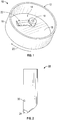
- liquid depth operated valve assembly 10 may be used in a variety of applications that require separating different density fluids, such as air and liquid, in a low or zero gravity environment.
- the liquid depth operated valve assembly 10 as according to claim 1 is employed in conjunction with a toilet on a space vehicle or space station, for example.
- liquid urine from an individual is transported by an air flow that directs the liquid urine into the liquid depth operated valve assembly 10, which then pumps the liquid urine into a storage tank for processing or dumping.
- Several alternative liquids and applications are contemplated and it is to be appreciated that the embodiment described above is not intended to be limiting of other low or zero gravity applications for the liquid depth operated valve assembly 10.
- the liquid depth-operated valve assembly 10 includes a centrifugal separator 12 that comprises a drum having an interior region 14 defined by at least one sidewall 16 and a pair of opposing walls 18, only one of which is illustrated for clarity.
- the centrifugal separator 12 may be formed of numerous geometries, such as the substantially cylindrical exemplary illustrated embodiment.
- the centrifugal separator 12 is configured to rotate, as shown with arrow 20. Rotation of the centrifugal separator 12 may be facilitated by a shaft operatively coupled to the centrifugal separator 12 and the rotation may be at various speeds that result in a desired centrifugal force on objects or matter disposed within the interior region 14.
- an inlet line is included and extends through the at least one sidewall 16 and/or one of the pair of opposing walls 18. The inlet line is configured to introduce a mixture of liquid and air into the interior region 14.
- a Pitot pump 22 is disposed at least partially within the interior region 14 of the centrifugal separator 12.
- the Pitot pump 22 is operatively coupled to at least one of the opposing walls 18 at a substantially central location 19 within the interior region 14 and is fixed in a stationary position, relative to the rotating centrifugal separator 12. From the central location, the Pitot pump 22 extends radially outwardly toward the at least one sidewall 16. In the illustrated embodiment, the Pitot pump 22 is not fully extended to the at least one sidewall 16, but it is to be understood that the Pitot pump 22 may extend to a radial location that is proximate the at least one sidewall 16.
- the centrifugal separator 12 imparts a centrifugal force on the mixture of liquid and air within the interior region 14 during rotation, thereby biasing the higher-density fluid to radially outward locations, thereby forming a liquid-air interface that substantially divides the liquid from the air. However, proximate the liquid-air interface, a mixture of liquid and air is present.
- This portion of the Pitot pump 22 includes a Pitot opening 24 disposed at a first radial location of the Pitot pump 22.
- the Pitot opening 24 leads to a Pitot pump fluid path 26 that functions as a fluid "pick-up" path for routing fluid from the interior region 14 to a location for pumping to a storage tank (not illustrated).
- the flow rate of fluid within the Pitot pump fluid path 26 is controlled by a valve 28.
- the Pitot opening 24 is substantially submerged in only liquid prior to opening the valve 28 to allow the flow of fluid through the Pitot pump fluid path 26.
- a depth-sensing port 30 is disposed at a second radial location along the Pitot pump 22 that is radially inward of the first radial location.
- first radial location and second radial location refer to locations along the Pitot pump 22, relative to the substantially central location 19 of the interior region 14.
- a total pressure comprising stagnation pressure and hydrostatic pressure is detected and communicated to the valve. Once this higher pressure is detected, the likelihood of liquid submersion of the Pitot opening 24 is increased.
- the depth-sensing port 30 is in operative communication with the valve 28 and is configured to communicate the pressure at the depth-sensing port 30 to the valve 28. Detecting and communicating the total pressure to the valve 28 may be performed in a number of structural manners.
- the depth-sensing port 30 is fluidly coupled to the valve 28 via a depth-sensing port fluid path 32 extending from the depth-sensing port 30 to a location proximate the valve 28.
- a pressure of the depth-sensing port 30 in a submerged condition is sufficient to open the valve 28.
- the valve 28 is configured to open at a critical pressure that will depend on the particular application, but once the critical pressure is exceeded, the valve 28 opens and the liquid is free to flow through the Pitot pump fluid path 26.
- a similar configuration as that described above may be employed, but the pressure proximate the depth sensing port 30 is communicated via an electrical signal to the valve 28 or a valve controller.
- a pressure-sensing device such as a pressure transducer is disposed proximate the depth-sensing port 30 and is configured to send the signal to the valve 28 or valve controller.
- the pressure signal may be amplified by a signal amplifier, such as a fluid transistor.
- a bore portion 40 is included at the depth-sensing port 30. Disposed within the bore portion 40 is a diaphragm 42 comprising an elastic membrane that isolates the depth-sensing port fluid path 32 from the liquid, thereby reducing or eliminating corrosive deposits from entering the depth-sensing port fluid path 32.
- a non-corrosive, incompressible fluid behind the diaphragm that transfers the pressure exerted by the liquid against the bore portion 40 of the depth sensing port 30 to the valve 28.
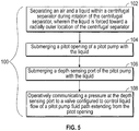
- a method of pumping liquid in a zero gravity environment 100 is also provided, as illustrated in FIG. 5 and with reference to FIGS. 1-4 .
- the liquid depth-operated valve 10 has been previously described and specific structural components need not be described in further detail.
- the method of pumping liquid in a zero gravity environment 100 includes separating 102 an air and a liquid within the centrifugal separator 12 during rotation of the centrifugal separator 12, wherein the liquid is forced toward a radially outer location of the centrifugal separator 12.
- the Pitot opening 24 of a Pitot pump is submerged 104 within the liquid.
- the depth-sensing port 30 is submerged 106 with the liquid.
- the pressure at the depth-sensing port 30 is operatively communicated 108 to the valve 28 that is configured to control liquid flow of the Pitot pumped fluid path 26.
- the method further includes disposing a diaphragm 42 proximate the depth-sensing port 30, and disposing a non-corrosive, incompressible fluid within a depth-sensing port fluid path 32 (in accordance to the embodiment described above and as shown in FIG. 4 ). While the invention has been described in detail in connection with only a limited number of embodiments, it should be readily understood that the invention is not limited to such disclosed embodiments.
Landscapes
- Engineering & Computer Science (AREA)
- Mechanical Engineering (AREA)
- General Engineering & Computer Science (AREA)
- Chemical & Material Sciences (AREA)
- Chemical Kinetics & Catalysis (AREA)
- Remote Sensing (AREA)
- Aviation & Aerospace Engineering (AREA)
- Structures Of Non-Positive Displacement Pumps (AREA)
- Control Of Non-Positive-Displacement Pumps (AREA)
Claims (7)
- Flüssigkeitsstandbetriebene Ventilanordnung (10) zur Verwendung unter Schwerelosigkeit, umfassend:eine Pitotpumpe (22), angeordnet innerhalb eines Fliehkraftabscheiders (12), ausgelegt um Luft und eine Flüssigkeit voneinander zu trennen;eine Pitotöffnung (24), angeordnet in einer ersten radialen Position entlang der Pitotpumpe (22) bezüglich einer im Wesentlichen zentralen Position (19) des Fliehkraftabscheiders (12) ;eine sich von der Pitotöffnung (24) erstreckende Pitotpumpen-Flüssigkeitspassage (26); undein Tiefensensoranschluss (30), angeordnet in einer zweiten radialen Position entlang der Pitotpumpe (22), die zweite radiale Position angeordnet zwischen der ersten radialen Position und der zentralen Position, der Tiefensensoranschluss (30) in operativer Verbindung mit einem Ventil (28) stehend,wobei das Ventil (28) ausgelegt ist, um die Flüssigkeitsströmung der Pitotpumpen-Flüssigkeitspassage (26) zu steuern;dadurch gekennzeichnet, dass:eine Membran (42), die unmittelbar an dem Tiefensensoranschluss (30) angeordnet ist, und eine korrosionsbeständige, nicht komprimierbare Flüssigkeit innerhalb einer Tiefensensoranschluss-Flüssigkeitspassage (32) angeordnet ist.
- Flüssigkeitsstandbetriebene Ventilanordnung nach Anspruch 1, wobei das Ventil (28) einen Gesamtdruck unmittelbar am Tiefensensoranschluss (30) erfasst.
- Flüssigkeitsstandbetriebene Ventilanordnung nach Anspruch 1 oder 2, eingebaut in ein Raumfahrzeug.
- Verfahren zum Pumpen von Flüssigkeit unter Schwerelosigkeit, umfassend:Trennen von Luft und einer Flüssigkeit innerhalb eines Fliehkraftabscheiders (12) während Rotation des Fliehkraftabscheiders (12), wobei die Flüssigkeit in Richtung einer radialen, äußeren Position des Fliehkraftabscheiders (12) gezwungen wird;Eintauchen einer Pitotöffnung (24) einer Pitotpumpe (22) in die Flüssigkeit, wobeidie Pitotöffnung (24) in einer ersten radialen Position entlang der Pitotpumpe (22) angeordnet ist;Eintauchen eines Tiefensensoranschlusses (30) der Pitotpumpe (22) in die Flüssigkeit, wobei der Tiefensensoranschluss (30) in einer zweiten radialen Position entlang der Pitotpumpe (22) angeordnet ist, die zweite radiale Position radial angeordnet zwischen der ersten radialen Position und der zentralen Position; undwirksames Übermitteln eines Drucks an dem Tiefensensoranschluss (30) zu einem Ventil (28), das ausgelegt ist, die Flüssigkeitsströmung einer sich von einer Pitotöffnung (24) erstreckenden Pitotpumpen-Flüssigkeitspassage (26) zu steuern,dadurch gekennzeichnet, dass:eine Membran (42), die unmittelbar an dem Tiefensensoranschluss (30) angeordnet ist, und eine korrosionsbeständige, nicht komprimierbare Flüssigkeit innerhalb einer Tiefensensoranschluss-Flüssigkeitspassage (32) angeordnet ist.
- Verfahren nach Anspruch 4, weiter umfassend Leiten der korrosionsbeständigen, nicht komprimierbaren Flüssigkeit entlang der Tiefensensoranschluss-Flüssigkeitspassage (32) von dem Tiefensensoranschluss (30) zu dem Ventil (28).
- Verfahren nach Anspruch 4 oder 5, weiter umfassend Erfassen eines Gesamtdrucks unmittelbar am Tiefensensoranschluss (30), wobei der Gesamtdruck einen Staudruck und einen hydrostatischen Druck umfasst.
- Verfahren nach Anspruch 6, wobei der Gesamtdruck an dem Tiefensensoranschluss (30) im eingetauchten Zustand größer ist als ein zum Öffnen des Ventils (28) benötigter kritischer Druck.
Applications Claiming Priority (1)
| Application Number | Priority Date | Filing Date | Title |
|---|---|---|---|
| US13/854,591 US20140290486A1 (en) | 2013-04-01 | 2013-04-01 | Liquid depth-operated valve assembly for use in a zero gravity environment and method |
Publications (2)
| Publication Number | Publication Date |
|---|---|
| EP2787217A1 EP2787217A1 (de) | 2014-10-08 |
| EP2787217B1 true EP2787217B1 (de) | 2017-12-06 |
Family
ID=50396916
Family Applications (1)
| Application Number | Title | Priority Date | Filing Date |
|---|---|---|---|
| EP14162042.7A Not-in-force EP2787217B1 (de) | 2013-04-01 | 2014-03-27 | Flüssigkeitsstandbetriebene Ventilanordnung zur Verwendung unter Schwerelosigkeit und Verfahren |
Country Status (2)
| Country | Link |
|---|---|
| US (1) | US20140290486A1 (de) |
| EP (1) | EP2787217B1 (de) |
Families Citing this family (2)
| Publication number | Priority date | Publication date | Assignee | Title |
|---|---|---|---|---|
| US10668428B2 (en) | 2016-08-24 | 2020-06-02 | Honeywell International Inc. | Apparatus and methods for enhancing gas-liquid contact/separation |
| US10722830B2 (en) * | 2018-01-16 | 2020-07-28 | Hamilton Sundstrand Corporation | Integrated pitot tube and fluid pickup port in rotary separator |
Family Cites Families (10)
| Publication number | Priority date | Publication date | Assignee | Title |
|---|---|---|---|---|
| DE844537C (de) * | 1941-07-25 | 1952-07-21 | Henschel & Sohn G M B H | Hydraulische Regeleinrichtung |
| US3213592A (en) * | 1963-02-21 | 1965-10-26 | Northern Ind Inc | Liquid treatment |
| US3224173A (en) * | 1964-12-31 | 1965-12-21 | Nasa | Liquid-gas separation system |
| US3936214A (en) * | 1975-01-22 | 1976-02-03 | Sun Oil Company | Pumping two-phase fluids |
| JPS59170700U (ja) * | 1983-04-30 | 1984-11-15 | 株式会社荏原製作所 | ストレ−ナ |
| US5145314A (en) * | 1991-04-18 | 1992-09-08 | Sundstrand Corporation | Low drag pitot pump and method of operating same |
| US5970999A (en) * | 1998-11-23 | 1999-10-26 | Maurice J. Greenia | Hydraulic vacuum pump |
| US20100069851A1 (en) * | 2008-09-17 | 2010-03-18 | Mobitech Regenerative Medicine | Method And Apparatus For Pressure Detection |
| WO2010037872A1 (es) * | 2008-10-02 | 2010-04-08 | Ibérica Del Espacio, S.A. | Plataforma térmica modular de nave espacial |
| WO2011163130A1 (en) * | 2010-06-22 | 2011-12-29 | Franklin Fueling Systems, Inc. | Apparatus and methods for conserving energy in fueling appalications |
-
2013
- 2013-04-01 US US13/854,591 patent/US20140290486A1/en not_active Abandoned
-
2014
- 2014-03-27 EP EP14162042.7A patent/EP2787217B1/de not_active Not-in-force
Non-Patent Citations (1)
| Title |
|---|
| None * |
Also Published As
| Publication number | Publication date |
|---|---|
| US20140290486A1 (en) | 2014-10-02 |
| EP2787217A1 (de) | 2014-10-08 |
Similar Documents
| Publication | Publication Date | Title |
|---|---|---|
| JP6013302B2 (ja) | 気泡除去方法、気泡除去装置、脱気装置、及びコンピュータ読み取り可能な記録媒体 | |
| WO2007035563A3 (en) | Malfunction detection via pressure pulsation | |
| JP6621349B2 (ja) | ポンプ | |
| EP2787217B1 (de) | Flüssigkeitsstandbetriebene Ventilanordnung zur Verwendung unter Schwerelosigkeit und Verfahren | |
| JP2002156092A (ja) | 水中軸受潤滑システム | |
| CA2561298A1 (en) | Systems and methods for determining flow rates of biological fluids | |
| JP7022927B2 (ja) | 脱気装置 | |
| CN116428037B (zh) | 旋转泵的转速随负载变化的流体输送系统 | |
| JP3713621B2 (ja) | 横軸ポンプ | |
| KR101798952B1 (ko) | 유체감지센서가 구비된 유체펌프 | |
| CN105570235B (zh) | 用于使液压液脱气的设备 | |
| CN113167060A (zh) | 使用入口压力的系统状态检测 | |
| JP2015031273A (ja) | ポンプ装置 | |
| JP5921085B2 (ja) | ポンプ装置及びポンプ装置を搭載した作業車 | |
| US20050271518A1 (en) | Pumping method and system | |
| JP2017096201A (ja) | ポンプ | |
| CN103244437B (zh) | 具有真空保持功能的高速引流透平同步排吸泵 | |
| JP7067505B2 (ja) | 燃料ポンプの診断装置 | |
| US5836745A (en) | Fluid recovery apparatus and method using a motive force | |
| WO2016125777A1 (ja) | 液体圧送装置 | |
| CN215370245U (zh) | 具有新型防沉淀堵塞平衡管结构的中开泵 | |
| CN205154963U (zh) | 液力偶合器 | |
| CN102869833B (zh) | 用于除气控制的结构 | |
| CN212502026U (zh) | 一种分液系统及生产系统 | |
| KR20250022203A (ko) | 탈포 장치 |
Legal Events
| Date | Code | Title | Description |
|---|---|---|---|
| PUAI | Public reference made under article 153(3) epc to a published international application that has entered the european phase |
Free format text: ORIGINAL CODE: 0009012 |
|
| 17P | Request for examination filed |
Effective date: 20140327 |
|
| AK | Designated contracting states |
Kind code of ref document: A1 Designated state(s): AL AT BE BG CH CY CZ DE DK EE ES FI FR GB GR HR HU IE IS IT LI LT LU LV MC MK MT NL NO PL PT RO RS SE SI SK SM TR |
|
| AX | Request for extension of the european patent |
Extension state: BA ME |
|
| R17P | Request for examination filed (corrected) |
Effective date: 20150407 |
|
| RBV | Designated contracting states (corrected) |
Designated state(s): AL AT BE BG CH CY CZ DE DK EE ES FI FR GB GR HR HU IE IS IT LI LT LU LV MC MK MT NL NO PL PT RO RS SE SI SK SM TR |
|
| 17Q | First examination report despatched |
Effective date: 20150925 |
|
| RIC1 | Information provided on ipc code assigned before grant |
Ipc: F04D 1/12 20060101AFI20160311BHEP Ipc: F04D 15/00 20060101ALI20160311BHEP Ipc: B01D 19/00 20060101ALI20160311BHEP Ipc: B64G 1/60 20060101ALI20160311BHEP |
|
| GRAP | Despatch of communication of intention to grant a patent |
Free format text: ORIGINAL CODE: EPIDOSNIGR1 |
|
| STAA | Information on the status of an ep patent application or granted ep patent |
Free format text: STATUS: GRANT OF PATENT IS INTENDED |
|
| INTG | Intention to grant announced |
Effective date: 20170619 |
|
| GRAS | Grant fee paid |
Free format text: ORIGINAL CODE: EPIDOSNIGR3 |
|
| GRAA | (expected) grant |
Free format text: ORIGINAL CODE: 0009210 |
|
| STAA | Information on the status of an ep patent application or granted ep patent |
Free format text: STATUS: THE PATENT HAS BEEN GRANTED |
|
| AK | Designated contracting states |
Kind code of ref document: B1 Designated state(s): AL AT BE BG CH CY CZ DE DK EE ES FI FR GB GR HR HU IE IS IT LI LT LU LV MC MK MT NL NO PL PT RO RS SE SI SK SM TR |
|
| REG | Reference to a national code |
Ref country code: GB Ref legal event code: FG4D |
|
| REG | Reference to a national code |
Ref country code: AT Ref legal event code: REF Ref document number: 952640 Country of ref document: AT Kind code of ref document: T Effective date: 20171215 Ref country code: CH Ref legal event code: EP |
|
| REG | Reference to a national code |
Ref country code: IE Ref legal event code: FG4D |
|
| REG | Reference to a national code |
Ref country code: DE Ref legal event code: R096 Ref document number: 602014018087 Country of ref document: DE |
|
| REG | Reference to a national code |
Ref country code: FR Ref legal event code: PLFP Year of fee payment: 5 |
|
| REG | Reference to a national code |
Ref country code: NL Ref legal event code: MP Effective date: 20171206 |
|
| REG | Reference to a national code |
Ref country code: LT Ref legal event code: MG4D |
|
| PG25 | Lapsed in a contracting state [announced via postgrant information from national office to epo] |
Ref country code: LT Free format text: LAPSE BECAUSE OF FAILURE TO SUBMIT A TRANSLATION OF THE DESCRIPTION OR TO PAY THE FEE WITHIN THE PRESCRIBED TIME-LIMIT Effective date: 20171206 Ref country code: ES Free format text: LAPSE BECAUSE OF FAILURE TO SUBMIT A TRANSLATION OF THE DESCRIPTION OR TO PAY THE FEE WITHIN THE PRESCRIBED TIME-LIMIT Effective date: 20171206 Ref country code: FI Free format text: LAPSE BECAUSE OF FAILURE TO SUBMIT A TRANSLATION OF THE DESCRIPTION OR TO PAY THE FEE WITHIN THE PRESCRIBED TIME-LIMIT Effective date: 20171206 Ref country code: SE Free format text: LAPSE BECAUSE OF FAILURE TO SUBMIT A TRANSLATION OF THE DESCRIPTION OR TO PAY THE FEE WITHIN THE PRESCRIBED TIME-LIMIT Effective date: 20171206 Ref country code: NO Free format text: LAPSE BECAUSE OF FAILURE TO SUBMIT A TRANSLATION OF THE DESCRIPTION OR TO PAY THE FEE WITHIN THE PRESCRIBED TIME-LIMIT Effective date: 20180306 |
|
| REG | Reference to a national code |
Ref country code: AT Ref legal event code: MK05 Ref document number: 952640 Country of ref document: AT Kind code of ref document: T Effective date: 20171206 |
|
| PG25 | Lapsed in a contracting state [announced via postgrant information from national office to epo] |
Ref country code: GR Free format text: LAPSE BECAUSE OF FAILURE TO SUBMIT A TRANSLATION OF THE DESCRIPTION OR TO PAY THE FEE WITHIN THE PRESCRIBED TIME-LIMIT Effective date: 20180307 Ref country code: BG Free format text: LAPSE BECAUSE OF FAILURE TO SUBMIT A TRANSLATION OF THE DESCRIPTION OR TO PAY THE FEE WITHIN THE PRESCRIBED TIME-LIMIT Effective date: 20180306 Ref country code: LV Free format text: LAPSE BECAUSE OF FAILURE TO SUBMIT A TRANSLATION OF THE DESCRIPTION OR TO PAY THE FEE WITHIN THE PRESCRIBED TIME-LIMIT Effective date: 20171206 Ref country code: HR Free format text: LAPSE BECAUSE OF FAILURE TO SUBMIT A TRANSLATION OF THE DESCRIPTION OR TO PAY THE FEE WITHIN THE PRESCRIBED TIME-LIMIT Effective date: 20171206 Ref country code: RS Free format text: LAPSE BECAUSE OF FAILURE TO SUBMIT A TRANSLATION OF THE DESCRIPTION OR TO PAY THE FEE WITHIN THE PRESCRIBED TIME-LIMIT Effective date: 20171206 |
|
| PG25 | Lapsed in a contracting state [announced via postgrant information from national office to epo] |
Ref country code: NL Free format text: LAPSE BECAUSE OF FAILURE TO SUBMIT A TRANSLATION OF THE DESCRIPTION OR TO PAY THE FEE WITHIN THE PRESCRIBED TIME-LIMIT Effective date: 20171206 |
|
| PG25 | Lapsed in a contracting state [announced via postgrant information from national office to epo] |
Ref country code: SK Free format text: LAPSE BECAUSE OF FAILURE TO SUBMIT A TRANSLATION OF THE DESCRIPTION OR TO PAY THE FEE WITHIN THE PRESCRIBED TIME-LIMIT Effective date: 20171206 Ref country code: EE Free format text: LAPSE BECAUSE OF FAILURE TO SUBMIT A TRANSLATION OF THE DESCRIPTION OR TO PAY THE FEE WITHIN THE PRESCRIBED TIME-LIMIT Effective date: 20171206 Ref country code: CZ Free format text: LAPSE BECAUSE OF FAILURE TO SUBMIT A TRANSLATION OF THE DESCRIPTION OR TO PAY THE FEE WITHIN THE PRESCRIBED TIME-LIMIT Effective date: 20171206 |
|
| PG25 | Lapsed in a contracting state [announced via postgrant information from national office to epo] |
Ref country code: SM Free format text: LAPSE BECAUSE OF FAILURE TO SUBMIT A TRANSLATION OF THE DESCRIPTION OR TO PAY THE FEE WITHIN THE PRESCRIBED TIME-LIMIT Effective date: 20171206 Ref country code: AT Free format text: LAPSE BECAUSE OF FAILURE TO SUBMIT A TRANSLATION OF THE DESCRIPTION OR TO PAY THE FEE WITHIN THE PRESCRIBED TIME-LIMIT Effective date: 20171206 Ref country code: RO Free format text: LAPSE BECAUSE OF FAILURE TO SUBMIT A TRANSLATION OF THE DESCRIPTION OR TO PAY THE FEE WITHIN THE PRESCRIBED TIME-LIMIT Effective date: 20171206 Ref country code: PL Free format text: LAPSE BECAUSE OF FAILURE TO SUBMIT A TRANSLATION OF THE DESCRIPTION OR TO PAY THE FEE WITHIN THE PRESCRIBED TIME-LIMIT Effective date: 20171206 |
|
| REG | Reference to a national code |
Ref country code: DE Ref legal event code: R097 Ref document number: 602014018087 Country of ref document: DE |
|
| PLBE | No opposition filed within time limit |
Free format text: ORIGINAL CODE: 0009261 |
|
| STAA | Information on the status of an ep patent application or granted ep patent |
Free format text: STATUS: NO OPPOSITION FILED WITHIN TIME LIMIT |
|
| REG | Reference to a national code |
Ref country code: CH Ref legal event code: PL |
|
| 26N | No opposition filed |
Effective date: 20180907 |
|
| PG25 | Lapsed in a contracting state [announced via postgrant information from national office to epo] |
Ref country code: SI Free format text: LAPSE BECAUSE OF FAILURE TO SUBMIT A TRANSLATION OF THE DESCRIPTION OR TO PAY THE FEE WITHIN THE PRESCRIBED TIME-LIMIT Effective date: 20171206 Ref country code: MC Free format text: LAPSE BECAUSE OF FAILURE TO SUBMIT A TRANSLATION OF THE DESCRIPTION OR TO PAY THE FEE WITHIN THE PRESCRIBED TIME-LIMIT Effective date: 20171206 Ref country code: DK Free format text: LAPSE BECAUSE OF FAILURE TO SUBMIT A TRANSLATION OF THE DESCRIPTION OR TO PAY THE FEE WITHIN THE PRESCRIBED TIME-LIMIT Effective date: 20171206 |
|
| REG | Reference to a national code |
Ref country code: BE Ref legal event code: MM Effective date: 20180331 |
|
| REG | Reference to a national code |
Ref country code: IE Ref legal event code: MM4A |
|
| PG25 | Lapsed in a contracting state [announced via postgrant information from national office to epo] |
Ref country code: LU Free format text: LAPSE BECAUSE OF NON-PAYMENT OF DUE FEES Effective date: 20180327 |
|
| PG25 | Lapsed in a contracting state [announced via postgrant information from national office to epo] |
Ref country code: IE Free format text: LAPSE BECAUSE OF NON-PAYMENT OF DUE FEES Effective date: 20180327 |
|
| PG25 | Lapsed in a contracting state [announced via postgrant information from national office to epo] |
Ref country code: CH Free format text: LAPSE BECAUSE OF NON-PAYMENT OF DUE FEES Effective date: 20180331 Ref country code: LI Free format text: LAPSE BECAUSE OF NON-PAYMENT OF DUE FEES Effective date: 20180331 Ref country code: BE Free format text: LAPSE BECAUSE OF NON-PAYMENT OF DUE FEES Effective date: 20180331 |
|
| PG25 | Lapsed in a contracting state [announced via postgrant information from national office to epo] |
Ref country code: MT Free format text: LAPSE BECAUSE OF NON-PAYMENT OF DUE FEES Effective date: 20180327 |
|
| PG25 | Lapsed in a contracting state [announced via postgrant information from national office to epo] |
Ref country code: TR Free format text: LAPSE BECAUSE OF FAILURE TO SUBMIT A TRANSLATION OF THE DESCRIPTION OR TO PAY THE FEE WITHIN THE PRESCRIBED TIME-LIMIT Effective date: 20171206 |
|
| PG25 | Lapsed in a contracting state [announced via postgrant information from national office to epo] |
Ref country code: HU Free format text: LAPSE BECAUSE OF FAILURE TO SUBMIT A TRANSLATION OF THE DESCRIPTION OR TO PAY THE FEE WITHIN THE PRESCRIBED TIME-LIMIT; INVALID AB INITIO Effective date: 20140327 Ref country code: PT Free format text: LAPSE BECAUSE OF FAILURE TO SUBMIT A TRANSLATION OF THE DESCRIPTION OR TO PAY THE FEE WITHIN THE PRESCRIBED TIME-LIMIT Effective date: 20171206 |
|
| PG25 | Lapsed in a contracting state [announced via postgrant information from national office to epo] |
Ref country code: CY Free format text: LAPSE BECAUSE OF FAILURE TO SUBMIT A TRANSLATION OF THE DESCRIPTION OR TO PAY THE FEE WITHIN THE PRESCRIBED TIME-LIMIT Effective date: 20171206 Ref country code: MK Free format text: LAPSE BECAUSE OF NON-PAYMENT OF DUE FEES Effective date: 20171206 |
|
| PG25 | Lapsed in a contracting state [announced via postgrant information from national office to epo] |
Ref country code: AL Free format text: LAPSE BECAUSE OF FAILURE TO SUBMIT A TRANSLATION OF THE DESCRIPTION OR TO PAY THE FEE WITHIN THE PRESCRIBED TIME-LIMIT Effective date: 20171206 Ref country code: IS Free format text: LAPSE BECAUSE OF FAILURE TO SUBMIT A TRANSLATION OF THE DESCRIPTION OR TO PAY THE FEE WITHIN THE PRESCRIBED TIME-LIMIT Effective date: 20180406 |
|
| PGFP | Annual fee paid to national office [announced via postgrant information from national office to epo] |
Ref country code: FR Payment date: 20210219 Year of fee payment: 8 Ref country code: IT Payment date: 20210217 Year of fee payment: 8 |
|
| PGFP | Annual fee paid to national office [announced via postgrant information from national office to epo] |
Ref country code: GB Payment date: 20210219 Year of fee payment: 8 Ref country code: DE Payment date: 20210217 Year of fee payment: 8 |
|
| REG | Reference to a national code |
Ref country code: DE Ref legal event code: R119 Ref document number: 602014018087 Country of ref document: DE |
|
| GBPC | Gb: european patent ceased through non-payment of renewal fee |
Effective date: 20220327 |
|
| PG25 | Lapsed in a contracting state [announced via postgrant information from national office to epo] |
Ref country code: GB Free format text: LAPSE BECAUSE OF NON-PAYMENT OF DUE FEES Effective date: 20220327 Ref country code: FR Free format text: LAPSE BECAUSE OF NON-PAYMENT OF DUE FEES Effective date: 20220331 Ref country code: DE Free format text: LAPSE BECAUSE OF NON-PAYMENT OF DUE FEES Effective date: 20221001 |
|
| PG25 | Lapsed in a contracting state [announced via postgrant information from national office to epo] |
Ref country code: IT Free format text: LAPSE BECAUSE OF NON-PAYMENT OF DUE FEES Effective date: 20220327 |