EP2787210B1 - Dispositif de mélange et turboréacteur doté d'un tel dispositif de mélange - Google Patents
Dispositif de mélange et turboréacteur doté d'un tel dispositif de mélange Download PDFInfo
- Publication number
- EP2787210B1 EP2787210B1 EP14163289.3A EP14163289A EP2787210B1 EP 2787210 B1 EP2787210 B1 EP 2787210B1 EP 14163289 A EP14163289 A EP 14163289A EP 2787210 B1 EP2787210 B1 EP 2787210B1
- Authority
- EP
- European Patent Office
- Prior art keywords
- wall
- coupling element
- mixing device
- section
- articulation
- Prior art date
- Legal status (The legal status is an assumption and is not a legal conclusion. Google has not performed a legal analysis and makes no representation as to the accuracy of the status listed.)
- Not-in-force
Links
- 230000008878 coupling Effects 0.000 claims description 63
- 238000010168 coupling process Methods 0.000 claims description 63
- 238000005859 coupling reaction Methods 0.000 claims description 63
- 238000011144 upstream manufacturing Methods 0.000 description 4
- 238000005253 cladding Methods 0.000 description 3
- 239000000446 fuel Substances 0.000 description 3
- 230000035515 penetration Effects 0.000 description 3
- 241000309551 Arthraxon hispidus Species 0.000 description 2
- 230000001419 dependent effect Effects 0.000 description 2
- 230000000694 effects Effects 0.000 description 1
- 239000003344 environmental pollutant Substances 0.000 description 1
- 239000000463 material Substances 0.000 description 1
- 238000013021 overheating Methods 0.000 description 1
- 230000002093 peripheral effect Effects 0.000 description 1
- 231100000719 pollutant Toxicity 0.000 description 1
- 238000007789 sealing Methods 0.000 description 1
- 238000009751 slip forming Methods 0.000 description 1
- XLYOFNOQVPJJNP-UHFFFAOYSA-N water Substances O XLYOFNOQVPJJNP-UHFFFAOYSA-N 0.000 description 1
Images


Classifications
-
- F—MECHANICAL ENGINEERING; LIGHTING; HEATING; WEAPONS; BLASTING
- F02—COMBUSTION ENGINES; HOT-GAS OR COMBUSTION-PRODUCT ENGINE PLANTS
- F02K—JET-PROPULSION PLANTS
- F02K3/00—Plants including a gas turbine driving a compressor or a ducted fan
- F02K3/02—Plants including a gas turbine driving a compressor or a ducted fan in which part of the working fluid by-passes the turbine and combustion chamber
- F02K3/04—Plants including a gas turbine driving a compressor or a ducted fan in which part of the working fluid by-passes the turbine and combustion chamber the plant including ducted fans, i.e. fans with high volume, low pressure outputs, for augmenting the jet thrust, e.g. of double-flow type
- F02K3/075—Plants including a gas turbine driving a compressor or a ducted fan in which part of the working fluid by-passes the turbine and combustion chamber the plant including ducted fans, i.e. fans with high volume, low pressure outputs, for augmenting the jet thrust, e.g. of double-flow type controlling flow ratio between flows
-
- F—MECHANICAL ENGINEERING; LIGHTING; HEATING; WEAPONS; BLASTING
- F02—COMBUSTION ENGINES; HOT-GAS OR COMBUSTION-PRODUCT ENGINE PLANTS
- F02K—JET-PROPULSION PLANTS
- F02K1/00—Plants characterised by the form or arrangement of the jet pipe or nozzle; Jet pipes or nozzles peculiar thereto
- F02K1/38—Introducing air inside the jet
- F02K1/386—Introducing air inside the jet mixing devices in the jet pipe, e.g. for mixing primary and secondary flow
-
- F—MECHANICAL ENGINEERING; LIGHTING; HEATING; WEAPONS; BLASTING
- F02—COMBUSTION ENGINES; HOT-GAS OR COMBUSTION-PRODUCT ENGINE PLANTS
- F02K—JET-PROPULSION PLANTS
- F02K1/00—Plants characterised by the form or arrangement of the jet pipe or nozzle; Jet pipes or nozzles peculiar thereto
- F02K1/06—Varying effective area of jet pipe or nozzle
-
- F—MECHANICAL ENGINEERING; LIGHTING; HEATING; WEAPONS; BLASTING
- F02—COMBUSTION ENGINES; HOT-GAS OR COMBUSTION-PRODUCT ENGINE PLANTS
- F02K—JET-PROPULSION PLANTS
- F02K1/00—Plants characterised by the form or arrangement of the jet pipe or nozzle; Jet pipes or nozzles peculiar thereto
- F02K1/46—Nozzles having means for adding air to the jet or for augmenting the mixing region between the jet and the ambient air, e.g. for silencing
- F02K1/48—Corrugated nozzles
-
- F—MECHANICAL ENGINEERING; LIGHTING; HEATING; WEAPONS; BLASTING
- F05—INDEXING SCHEMES RELATING TO ENGINES OR PUMPS IN VARIOUS SUBCLASSES OF CLASSES F01-F04
- F05D—INDEXING SCHEME FOR ASPECTS RELATING TO NON-POSITIVE-DISPLACEMENT MACHINES OR ENGINES, GAS-TURBINES OR JET-PROPULSION PLANTS
- F05D2250/00—Geometry
- F05D2250/60—Structure; Surface texture
- F05D2250/61—Structure; Surface texture corrugated
Definitions
- the invention relates to a mixing device for mixing a first gas stream with a second gas stream in a turbofan engine, with an actuator and a wall defining a radially inner channel for the first gas stream and a radially outer channel for the second gas stream, wherein the Betuschistsemcardi a coupling element which is coupled to the wall, wherein the actuating device is designed to pivot by means of the coupling element, the wall from a first position to a radially outwardly to the first position arranged second position.
- a sheath flow of a fan and a core flow of an aircraft gas turbine by mixing a sheath flow of a fan and a core flow of an aircraft gas turbine, a reduction in noise and a reduction in specific fuel consumption can be achieved.
- the mixing is conventionally carried out via a mixing device positioned downstream of a low-pressure turbine of the aircraft gas turbine with a meander-shaped contour, by means of which at least a partial flow of the lateral flow is directed radially inwards and at least a partial flow of the core flow is directed radially outwards alternately.
- a flower mixer mixing devices are, for example, in the DE 10 2010 014 909 A1 or DE 10 2010 014 910 A1 shown.
- the contour of the mixing device is thereby varied.
- the deflection of the core or sheath current can be changed.
- the deflection is limited by the elasticity of the material.
- a mixing device according to the preamble of claim 1 is known for example from US 5,771,681 A and from the US 3,362,431 A known.
- an improved mixing apparatus for mixing a first gas stream with a second gas stream in a turbofan engine may be provided by the mixing apparatus comprising an actuator and a wall having a radially inner channel for the first gas stream and a radially outer one Channel for the second gas flow limited.
- the actuating device comprises a coupling element, which is coupled to the wall, wherein the actuating device is designed to pivot by means of the coupling element, the wall between a first position in a radially outward to the first position arranged second position.
- the actuating device comprises a rotatable between a first rotational position and a second rotational position in the circumferential direction adjusting ring, which is connected to the coupling element.
- the coupling element is rigid and coupled to the adjusting ring such that is pivoted by a rotation of the adjusting ring between the first rotational position and the second rotational position, the wall by the coupling element between the first position and the second position corresponding to the rotation of the adjusting ring.
- the first position and the second position can be selected radially far apart and at the same time a compact and robust design of the actuator for pivoting the wall can be provided.
- the compactness manifests itself in the fact that a particularly small radial space is required for this purpose.
- a support structure is further provided, which is arranged in the axial direction adjacent to the wall, wherein the support structure comprises a fastening element, wherein the adjusting ring is arranged axially between the fastening element and the wall and is connected to a further coupling element with the fastening element.
- the coupling element comprises a coupling rod and at least one joint is provided with a first joint portion and a second joint portion connected to the first joint portion, wherein the first joint portion relative to the second joint portion is pivotable about at least one axis, in particular about two axes, wherein the first hinge portion at least a longitudinal end of the coupling rod is arranged, and wherein the second hinge portion is coupled to the fastening element or the adjusting ring or the wall.
- the coupling element and the further coupling element are identical. In this way, a low-cost mixing device can be provided.
- the coupling element has a longitudinal extent, which is different from a longitudinal extension of the further coupling element.
- the wall comprises a first wall section and a second wall section arranged radially outside the first wall section, wherein the coupling element is connected to the first wall section and wherein the second wall section is coupled to the first wall section.
- the first wall section can be pivoted when a further joint is arranged on the support structure, which connects the first wall section pivotally about a pivot axis with the support structure, wherein the pivot axis is arranged perpendicular to a rotational axis of the adjusting ring.
- turbofan engine comprises a fan, an aircraft gas turbine coupled to the fan and a mixing device, the aircraft gas turbine having a first gas flow and the fan a second gas flowing radially outside the first gas flow Gas stream provides.
- the mixing device is downstream on the Air turbine arranged and designed to at least partially mix the first gas stream with the second gas stream, wherein the mixing device is formed as explained above.
- Fig. 1 shows a schematic sectional view through a turbofan engine 10 with a mixing device 30th
- the turbofan engine 10 is disposed in an engine nacelle 15 and includes an aircraft gas turbine 20, a fan 25 disposed upstream of the aircraft gas turbine 20, and the mixer 30 disposed downstream of the aircraft gas turbine 20. Further, elements of the aircraft gas turbine 20 and fan 25 are rotatable about one Rotary axis 31 of the turbofan engine 20 is arranged.
- a generated airflow is split at a flow divider 35.
- a radially inward-flowing part of the air flow also called core or primary flow, is passed through the aircraft gas turbine 20 and leaves the aircraft gas turbine 20 downstream as a hot air flow 40 (dotted line) between an exhaust cone 45 and the mixing device 30.
- the mixing device 30 is formed in a mixing plane 61 to mix the cold air stream 50 with the hot air stream 40 in order to reduce the fuel consumption of the aircraft gas turbine 20 or the noise emissions of the turbofan engine 10.
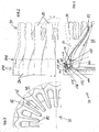
- FIG. 2 shows a side view of in Fig. 1 shown mixing device 30 and Fig. 3 a rear view of the in Fig. 2 shown mixing device 30.
- Figure 4 is a longitudinal section through the in Fig. 2 shown mixing device 30 along a in Fig. 2 shown sectional plane AA and shown Fig. 5 shows an exploded view of the in Fig. 4 shown mixing device 30 with an actuator 95th Fig. 6 shows an exploded view of the in Fig. 5 shown actuator 95.
- FIGS. 1 to 6 be explained together for ease of understanding.
- the mixing device 30 comprises a wall 60, which is designed to limit the radially inwardly flowing hot air stream 40 in a first channel 65 between the exhaust cone 45 and the wall 60. Further, the wall 60 bounded radially outside a second channel 70 which extends between the inner wall 55 and the wall 60. In the second channel 70, the cold air stream 50 coming from the fan 25 is performed.
- the mixing device 30 is designed to mix the hot air stream 40 with the cold air stream 50 in order to reduce the fuel consumption of the turbofan engine 10.
- the mixing device 30 is designed as a flower mixer, wherein the wall 60 comprises a plurality of circumferentially arranged adjacent wall portions 75, 80.
- a second wall section 80 which is coupled to the first wall section 75, is provided on a first wall section 75.
- the second wall section 80 comprises a radially inwardly extending first guide contour 85 and a radially outwardly to the first guide contour 85 extending second guide contour 90.
- first guide contour 85 a radially inward of both the cold air flow 50 and the hot air flow 40 is reached.
- second guide contour 90 With the second guide contour 90, a flow of the cold air flow 50 radially outward and the hot air flow 40 is achieved. In this way, the hot and cold air streams 40, 50 are alternately guided in the circumferential direction and reliably mixed by a transverse flow component in the cold or hot air stream 40, 50 in the circumferential direction.
- an actuating device 95 is provided.
- the actuator 95 is coupled to the wall 60.
- the actuator 95 pivots depending on the operating point, the wall 60 between a first position (by a solid line in Fig. 4 shown), which is arranged for example radially inward, and a second position (in Fig. 4 represented by a dashed line), which is arranged for example radially outward.
- This causes that in the first position, the cold air flow 50 is guided more inwardly than in the second position of the wall 60, in which the cold air stream 50 can flow radially outward than in the first position of the wall 60.
- the two positions can be dependent be selected from the respective load or operating state of the aircraft gas turbine 20. Of course, it is also conceivable, depending on the operating point between the two positions lying positions of the wall to approach by the actuator 95.
- the actuating device 95 is arranged radially on the outside on a support structure 100.
- the support structure 100 is arranged on the downstream side of the aircraft gas turbine 20 and connected to a non-rotatable structure, not shown, of the aircraft gas turbine 20.
- the actuating device 95 comprises an adjusting ring 105 and a plurality of circumferentially distributed coupling elements 110.
- the coupling elements 110 are rigid.
- On the support structure 100 also distributed circumferentially equidistant fastening elements 115 are arranged radially on the outside of the support structure 100.
- the support structure 100 includes a stepped radially outwardly extending configuration. It is (cf. Fig.
- a first hinge opening 130 is arranged.
- a second portion 135 is arranged.
- the first section 120 and the second section 135 are connected by means of a first connecting web 136.
- the first connecting web 136 is aligned obliquely to the rotational axis 31 and prevents penetration of the hot air stream 40 between the first and the second section 120, 135 of the support structure 100.
- the second section 135 is arranged substantially parallel to the axis of rotation 31 of the aircraft gas turbine 20. Radially on the outside, the second section 135 comprises a guide surface 140.
- the guide surface 140 is offset radially outwards relative to the remaining second section 135.
- the guide surface 140 is continuously formed on the second portion 135 extending or radially offset inwardly.
- the fastening elements 115 are arranged radially on the outside of the third section 141.
- the third section 141 and the second section 135 are connected via a second peripheral connecting web 142.
- the second connecting web 142 is also arranged perpendicular to the axis of rotation 31 and prevents penetration of the hot air stream 40 between the second and third sections 135, 141 and thus prevents overheating of the components of the actuating device 95 arranged downstream of the support structure 100.
- the adjusting ring 105 comprises a ring element 145 and a guide element 150, which is arranged radially on the inside and on the side 60 of the wall facing the adjusting ring 105.
- the guide element 150 comprises a first guide element section 151 arranged perpendicular to the axis of rotation 31 and a second guide element section 152 arranged radially inwardly to the first guide element section 151.
- the guide element 150 is connected to the ring element 145 via the first guide element section 151.
- On the second guide element section 152 a V-shaped bearing section 153 is provided radially inwardly of the adjusting ring 145 on the side facing the guide surface 140, which rests on the guide surface and fixes or supports the adjusting ring 105 radially in its position.
- the ring element 145 comprises a plurality of first rectangular shaped receptacles 155, which are circumferentially arranged in pairs side by side at a uniform spacing.
- first receptacles 155 engages in each case an upstream side and a downstream side of the ring member 145 arranged coupling element 110 a.
- the upstream-side coupling element 110 is connected via the first receptacle 155 with the ring element 145 at a first longitudinal end of the coupling element 110 and at a second longitudinal end of the coupling element 110 with the fastening element 115.
- the first receptacles 155 each include two oppositely disposed first hinge pin receptacles 156, which are arranged on an axis 157 perpendicular to the axis of rotation 31.
- first hinge pin receptacles 156 are distributed irregularly, individually and / or grouped along the circumference of the ring element 145.
- first receptacles 155 are differently formed, for example, in terms of their cross-section.
- the fastening element 115 of the support structure 100 is identical to the first receptacle 155 and distributed circumferentially along the support structure 100 corresponding to the first receptacles 155.
- the wall 60 comprises on the first wall section 75 a hinge web 160 which extends in the radial direction and substantially parallel to the axis of rotation 31 and which is arranged radially on the outside on the first wall section 75.
- the hinge web 160 includes a hinge bore 165 disposed upstream, radially outward of the first guide contour 85 and adjacent to the hinge web 160.
- a coupling receptacle 170 is arranged, which comprises two parallel extending tab members 175.
- a second hinge pin receptacle 180 is provided in the tab elements 175 in order to receive a first hinge pin 185 running radially in the direction of the axis of rotation 31 (cf. Fig. 5 ).
- the webs 125 are arranged parallel to the first portion 120 of the support structure 110 and laterally engage around the hinge web 160 on the joint bore 165 and abut against a respective side surface 190 of the joint web 160 in the region of the joint bore 165.
- a second hinge pin 195 is further guided to provide a hinge 196 for pivoting the first wall portion 75 about a pivot axis 200 which is aligned perpendicular to the axis of rotation 31 of the aircraft gas turbine 20.
- the coupling element 110 comprises at a first longitudinal end a second receptacle 205 and at a second longitudinal end a third receptacle 210.
- the second or third receptacle 205, 210 are formed on the inside spherical shell-like.
- a coupling rod 215 is arranged, which is formed in a straight line and connects the second receptacle 205 with the third receptacle 210.
- the two receivers 205, 210 surround on the circumference a condyle 220, which on the outside in its design is adapted to the spherical shell-like configuration of the second receptacle 205 or third receptacle 210.
- the condyle 220 is circumferentially encompassed by the receptacles 205, 210, the condyle 220 is in touching contact with its associated second and third receptacle 205, 210 in order to be fixed by the respective receptacle 205, 210 in its position.
- the condyle 220 and the receptacles 205, 210 each form a joint 221, the second and third receptacles 205, 210 each representing a first joint portion, which relative to the condyle 220 as a second joint portion in at least two planes or about the axis 157 and a further pivot axis 222 can be inclined, which is aligned perpendicular to the axis 157.
- the condyle 220 may be pressed into the second and third receptacle 205, 210.
- the joint 221 is formed as a ball joint, of course, other joint designs would be conceivable, provided pivoting of the coupling rod 215 relative to the ring member 145 in two planes is possible.
- the joint head 220 comprises a third hinge pin receptacle 225.
- the first hinge pin 185 is guided by the third hinge pin receptacle 225 in the assembled state of the mixing device 30, which is further guided by the first hinge pin receptacle 156 of the first receptacle 155 of the ring element 145 is guided and thus the coupling element 110 connects to the second receptacle 205 with the ring member 145.
- a further first hinge pin 185 is further guided, which connects the coupling element 110 with the hinge web 160.
- the ring element 145 can be easily coupled to the hinge web 160.
- the coupling element 110 On the left side or upstream side, ie the side of the ring element 145 facing away from the wall 60, the coupling element 110 is connected to the first receptacle 155 of the ring element 145 or to the fastening element 115 by means of the first hinge pin 185. Further, by fastening the adjusting ring 105 with the coupling elements 110, both on the fastening element 115 and on the coupling receptacle 170, its axial position relative to the supporting structure 100 is defined.
- both the second and the third receptacles 205, 210 are formed identical to one another.
- the second or third receptacle 205, 210 or a to the second and third receptacle 205, 210 associated condyle 220 are formed deviating from each other.
- the two coupling rods 215 are identical in their longitudinal extent.
- an embodiment to that effect is conceivable that in the Figures 5 and 6 On the left side arranged coupling element 110 has a coupling rod 215, whose longitudinal extent deviating from that in the Figures 5 and 6 arranged on the right side coupling element 110 and its coupling rod 215.
- the adjusting ring 105 is provided with a in Fig. 6 Actuator 235 shown schematically coupled.
- the actuator 235 can in turn be connected to a control device, not shown, which is designed to control the actuator 235 and / or to provide energy.
- the actuator 235 is configured to rotate the adjusting ring 105 between a first rotational position (in FIG Fig. 6 shown by solid lines) and a second rotational position (in Fig. 6 represented by dashed lines) to rotate about the axis of rotation 31 of the aircraft gas turbine 20.
- the actuator 235 may be formed, for example, as a mechanical electrical, electro-mechanical, pneumatic and / or hydraulic actuator 235. Of course, other operating modes or combinations of mentioned embodiments of the actuator 235 are conceivable. It is also conceivable to arrange the actuator 235 at a position as radially outside the first section 120 of the support structure 110.
- Fig. 5 is schematically shown a deflection of the coupling elements 110 in the rotation of the adjusting ring 105 in the second rotational position by means of dashed lines.
- an axial distance d between the joint web 160 and the adjusting ring 105 is shortened during the rotation of the adjusting ring 105 from the first rotational position to the second rotational position 105, so that the first wall section 75 is raised or raised its first position in its second position, which correlates with the second rotational position, is moved.
- the first wall portion 75 pivots radially outward about the hinge axis 200.
- this is also pivoted radially outwardly about the hinge axis 200.
- the first channel 65 between the wall 60 and the exhaust cone 45 is widened.
- first rotational position and the second rotational position or the first position of the first wall portion 75 and the second position of the wall 60 also intermediate rotational positions or positions can be approached, so that a continuous adjustment of the wall 60th and thus a continuous adjustment of a cross section of the first channel 65 and the second channel 70 in a mixing plane 61 can be set.
- the turbofan engine 10 or the mixing device 30 can be tuned to different operating points of the turbofan engine 10, so that the turbofan engine 10 has a lower overall noise emission or lower pollutant emissions.
- the support structure 100 and its individual sections 120, 135, 141 are integrally connected. Furthermore, the individual sections 120, 135, 141 are arranged in such a stepped manner relative to one another that the actuating device 95 is arranged completely downstream of the support structure 100 and thus lies in the dead water area of the support structure 100.
- a sealing element is provided on the support structure 100 to seal the support structure 100 radially outwardly to a panel 240 towards.
- the cladding 240 is formed in individual cladding segments 241 and has an overlap portion 245, with which the cladding 240 overlaps with the second wall portion 80, so that an entry of the cold air flow 50 into the mixing device 30 is avoided.
- the overlapping section 245 is designed such that in each of the approached position of the second wall section 80, the covering 240 rests radially on the outside on the second wall section 80. In this way, furthermore, a mixing of hot air flow 40 and cold air flow 50 within the mixing device 30, in particular within the actuating device 95, is reliably avoided.
Landscapes
- Engineering & Computer Science (AREA)
- Chemical & Material Sciences (AREA)
- Combustion & Propulsion (AREA)
- Mechanical Engineering (AREA)
- General Engineering & Computer Science (AREA)
- Structures Of Non-Positive Displacement Pumps (AREA)
Claims (9)
- Dispositif de mélange (30) permettant de mélanger un premier flux de gaz (40) à un deuxième flux de gaz (50) dans un turboréacteur à double flux (20),- comportant un dispositif d'actionnement (95) et une paroi (60) qui délimite un canal (65) radialement intérieur pour le premier flux de gaz (40) et un canal (70) radialement extérieur pour le deuxième flux de gaz (50),- le dispositif d'actionnement (95) comportant un élément de couplage (110) qui est couplé à la paroi (60),- le dispositif d'actionnement (95) étant réalisé pour faire pivoter, au moyen de l'élément de couplage (110), la paroi (60) entre une première position vers une deuxième position disposée radialement à l'extérieur par rapport à la première position,- le dispositif d'actionnement (95) comportant une bague de réglage (105), qui est apte à tourner dans le sens circonférentiel entre une première position de rotation et une deuxième position de rotation et qui est reliée à l'élément de couplage (110),- l'élément de couplage (110) étant rigide et étant couplé à la bague de réglage (105) de telle sorte que sous l'effet d'une rotation de la bague de réglage (105) entre la première position de rotation et la deuxième position de rotation, la paroi (60) est amenée à pivoter par l'élément de couplage (110) entre la première position et la deuxième position en correspondance avec la rotation de la bague de réglage (105),caractérisé par une structure de support (100) qui est disposée dans le sens axial de manière adjacente à la paroi (60), la structure de support (100) comportant un élément de fixation (115), la bague de réglage (105) étant disposée axialement entre l'élément de fixation (115) et la paroi (60) et étant reliée à l'élément de fixation (115) par un élément de couplage (110) supplémentaire.
- Dispositif de mélange (30) selon la revendication 1, caractérisé en ce que isolément de couplage (110) et l'élément de couplage (110) supplémentaire sont disposés l'un à côté de l'autre dans le sens circonférentiel en étant adjacents à la bague de réglage (105).
- Dispositif de mélange (30) selon l'une quelconque des revendications précédentes, caractérisé en ce que l'élément de couplage (110) comporte une tige de couplage (215), et il est prévu au moins une articulation (221) avec une première portion d'articulation (205, 210) et avec une deuxième portion d'articulation (220) reliée à la première portion d'articulation (205, 210), ladite première portion d'articulation (205, 210) étant apte à pivoter par rapport à la deuxième portion d'articulation (220) autour d'au moins un axe (157, 222), en particulier autour de deux axes (157, 222), la première portion d'articulation (205, 210) étant disposée sur au moins une extrémité longitudinale de la tige de couplage (215), et la deuxième portion d'articulation (220) étant couplée à l'élément de fixation (115) ou à la bague de réglage (105) ou à la paroi (60).
- Dispositif de mélange (30) selon la revendication 2 ou 3, caractérisé en ce que l'élément de couplage (110) et l'élément de couplage (110) supplémentaire sont réalisés de manière identique.
- Dispositif de mélange (30) selon la revendication 2 ou 3, caractérisé en ce que l'élément de couplage (110) possède une extension longitudinale qui diffère de l'extension longitudinale de l'élément de couplage (110) supplémentaire.
- Dispositif de mélange (30) selon l'une quelconque des revendications précédentes, caractérisé en ce que la paroi (60) comporte une première portion de paroi (75) et une deuxième portion de paroi (80) disposée radialement à l'extérieur par rapport à la première portion de paroi (75), l'élément de couplage (110) étant relié à la première portion de paroi (75), et la deuxième portion de paroi (80) étant couplée à la première portion de paroi (75).
- Dispositif de mélange (30) selon la revendication 6, caractérisé en ce que sur la structure de support (100) est disposée une articulation (196) supplémentaire, par laquelle la première portion de paroi (75) est reliée à la structure de support (100) de manière à pouvoir pivoter autour d'un axe de pivotement (200), ledit axe de pivotement (200) de l'articulation (196) étant disposé perpendiculairement à un axe de rotation (31) de la bague de réglage (105).
- Dispositif de mélange (30) selon la revendication 7, caractérisé en ce que sur la première portion de paroi (75) est disposée, sur le côté extérieur, une traverse d'articulation (160), l'élément de couplage (110) étant reliée à la traverse d'articulation (160) au niveau de la traverse d'articulation (160) radialement à l'extérieur à distance de l'axe de pivotement (200).
- Turboréacteur à double flux (20) comportant une soufflante (25), une turbine à gaz (20) couplée à la soufflante (25) et un dispositif de mélange (30), la turbine à gaz (20) étant réalisée pour mettre à disposition un premier flux de gaz (40) et à la soufflante (25) un deuxième flux de gaz (50) circulant radialement à l'extérieur par rapport au premier flux de gaz (40), le dispositif de mélange (30) étant disposé du côté aval sur la turbine à gaz (20) et étant réalisé pour mélanger au moins partiellement le premier flux de gaz (40) avec le deuxième flux de gaz (50), caractérisé en ce que le dispositif de mélange (30) est réalisé selon l'une des revendications précédentes.
Applications Claiming Priority (1)
| Application Number | Priority Date | Filing Date | Title |
|---|---|---|---|
| DE102013205911.6A DE102013205911A1 (de) | 2013-04-04 | 2013-04-04 | Mischvorrichtung und Turbofantriebwerk mit einer derartigen Mischvorrichtung |
Publications (2)
| Publication Number | Publication Date |
|---|---|
| EP2787210A1 EP2787210A1 (fr) | 2014-10-08 |
| EP2787210B1 true EP2787210B1 (fr) | 2015-10-14 |
Family
ID=50439211
Family Applications (1)
| Application Number | Title | Priority Date | Filing Date |
|---|---|---|---|
| EP14163289.3A Not-in-force EP2787210B1 (fr) | 2013-04-04 | 2014-04-03 | Dispositif de mélange et turboréacteur doté d'un tel dispositif de mélange |
Country Status (3)
| Country | Link |
|---|---|
| US (1) | US9771896B2 (fr) |
| EP (1) | EP2787210B1 (fr) |
| DE (1) | DE102013205911A1 (fr) |
Families Citing this family (2)
| Publication number | Priority date | Publication date | Assignee | Title |
|---|---|---|---|---|
| FR2994712B1 (fr) * | 2012-08-27 | 2018-04-13 | Safran Aircraft Engines | Procede d'assemblage d'une tuyere et d'un carter d'echappement d'une turbomachine |
| US10082043B2 (en) | 2015-06-25 | 2018-09-25 | Pratt & Whitney Canada Corp. | Segmented multi-lobe mixer |
Family Cites Families (9)
| Publication number | Priority date | Publication date | Assignee | Title |
|---|---|---|---|---|
| GB1002116A (en) * | 1964-04-24 | 1965-08-25 | Rolls Royce | Fluid flow control apparatus |
| FR1405358A (fr) * | 1964-05-27 | 1965-07-09 | Nord Aviation | Procédé et dispositif de mélange rapide de fluides notamment sur un combiné turbostatoréacteur |
| US3556246A (en) * | 1969-06-16 | 1971-01-19 | Rohr Corp | Method and apparatus for suppressing the noise of a fan jet engine |
| US5372006A (en) * | 1993-02-08 | 1994-12-13 | Aeronautical Concept Of Exhaust, Ltd. | Turbine engine equipped with thrust reverser |
| US5771681A (en) * | 1996-09-17 | 1998-06-30 | The Boeing Company | Aircraft turbofan engine mixing apparatus |
| DE69918531T2 (de) * | 1999-05-13 | 2005-08-18 | Industria De Turbo Propulsores S.A., Zamudio | Verstelleinrichtung für den Auslassquerschnitt einer konvergent-divergenten Schubdüse |
| US6966175B2 (en) * | 2003-05-09 | 2005-11-22 | The Nordam Group, Inc. | Rotary adjustable exhaust nozzle |
| DE102010014909A1 (de) | 2010-04-14 | 2011-10-20 | Rolls-Royce Deutschland Ltd & Co Kg | Variabler Mischer für ein Turbofantriebwerk |
| DE102010014910A1 (de) | 2010-04-14 | 2011-10-20 | Rolls-Royce Deutschland Ltd & Co Kg | Mischvorrichtung für ein Turbofantriebwerk |
-
2013
- 2013-04-04 DE DE102013205911.6A patent/DE102013205911A1/de not_active Withdrawn
-
2014
- 2014-04-03 US US14/244,050 patent/US9771896B2/en not_active Expired - Fee Related
- 2014-04-03 EP EP14163289.3A patent/EP2787210B1/fr not_active Not-in-force
Also Published As
| Publication number | Publication date |
|---|---|
| EP2787210A1 (fr) | 2014-10-08 |
| DE102013205911A1 (de) | 2014-10-09 |
| US9771896B2 (en) | 2017-09-26 |
| US20140298772A1 (en) | 2014-10-09 |
Similar Documents
| Publication | Publication Date | Title |
|---|---|---|
| EP2960437B1 (fr) | Système d'aubes de guidage variables pour une turbine à gaz et turbine à gaz dotée d'un tel système | |
| DE102015201805B4 (de) | Abgasturbolader | |
| EP2604919A1 (fr) | Buse à combustible pour deux carburants | |
| EP2989298B1 (fr) | Turbocompresseur à gaz d'échappement | |
| DE60313893T2 (de) | Schubumkehrvorrichtung mit optimiertem strahlumkehrgitter | |
| DE2815573A1 (de) | Abgasduese mit veraenderlichem durchtrittsquerschnitt fuer gasturbinen und hebelgetriebeanordnung fuer eine solche abgasduese | |
| EP3330490B1 (fr) | Système d'étanchéité pour turbomachines | |
| CH703871B1 (de) | Verstellleitapparatanordnung für einen Verdichter. | |
| EP1984601A1 (fr) | Turbocompresseur pourvu d'aubes directrices réglables, d'un levier d'aubes et d'une bague de réglage à cet effet | |
| DE102012106888B4 (de) | Abgasklappenanordnung mit integriertem Bypass | |
| DE102015004649A1 (de) | Leitschaufelverstellvorrichtung und Strömungsmaschine | |
| WO2013127664A1 (fr) | Turbocompresseur doté d'anneaux de grille directrice pouvant tourner les uns par rapport aux autres | |
| WO2019121022A1 (fr) | Tuyère de poussée pour un turboréacteur d'un avion supersonique | |
| DE112012002909T5 (de) | Abgasturbolader | |
| EP3009683A1 (fr) | Système et procédé pour prélèvement d'air de compresseur d'un propulseur | |
| DE112014005008T5 (de) | Turbine mit variabler Eintrittsquerschnittsfläche | |
| EP2787210B1 (fr) | Dispositif de mélange et turboréacteur doté d'un tel dispositif de mélange | |
| DE102017129359A1 (de) | Anordnung mit einer Presse, mit zwei Bauteilen und mit wenigstens einem Spannelement | |
| DE2834860A1 (de) | Verstellbarer stroemungsteiler fuer stroemungsmaschinen, insbesondere gasturbinenstrahltriebwerke | |
| EP2020544B1 (fr) | Soupape, en particulier soupape de recyclage de gaz d'échappement | |
| EP2592258B1 (fr) | Soupape de recyclage de gaz d'échappement | |
| EP3472438B1 (fr) | Segment annulaire de turbine et système destiné à la délimitation extérieure d'un trajet d'écoulement d'une turbine | |
| EP3081788B1 (fr) | Installation d'echappement comprenant une soupape de commande | |
| EP2225467B1 (fr) | Appareil de production de rotation et turbocompresseur équipé d'un tel appareil | |
| EP3366908A1 (fr) | Tuyère d'éjection convergente-divergente pour un turboréacteur à double flux d'un avion supersonique |
Legal Events
| Date | Code | Title | Description |
|---|---|---|---|
| PUAI | Public reference made under article 153(3) epc to a published international application that has entered the european phase |
Free format text: ORIGINAL CODE: 0009012 |
|
| 17P | Request for examination filed |
Effective date: 20140403 |
|
| AK | Designated contracting states |
Kind code of ref document: A1 Designated state(s): AL AT BE BG CH CY CZ DE DK EE ES FI FR GB GR HR HU IE IS IT LI LT LU LV MC MK MT NL NO PL PT RO RS SE SI SK SM TR |
|
| AX | Request for extension of the european patent |
Extension state: BA ME |
|
| R17P | Request for examination filed (corrected) |
Effective date: 20150309 |
|
| RBV | Designated contracting states (corrected) |
Designated state(s): AL AT BE BG CH CY CZ DE DK EE ES FI FR GB GR HR HU IE IS IT LI LT LU LV MC MK MT NL NO PL PT RO RS SE SI SK SM TR |
|
| REG | Reference to a national code |
Ref country code: DE Ref legal event code: R079 Ref document number: 502014000139 Country of ref document: DE Free format text: PREVIOUS MAIN CLASS: F02K0001380000 Ipc: F02K0003075000 |
|
| GRAP | Despatch of communication of intention to grant a patent |
Free format text: ORIGINAL CODE: EPIDOSNIGR1 |
|
| INTG | Intention to grant announced |
Effective date: 20150716 |
|
| RIC1 | Information provided on ipc code assigned before grant |
Ipc: F02K 1/38 20060101ALI20150707BHEP Ipc: F02K 3/075 20060101AFI20150707BHEP |
|
| GRAS | Grant fee paid |
Free format text: ORIGINAL CODE: EPIDOSNIGR3 |
|
| GRAA | (expected) grant |
Free format text: ORIGINAL CODE: 0009210 |
|
| AK | Designated contracting states |
Kind code of ref document: B1 Designated state(s): AL AT BE BG CH CY CZ DE DK EE ES FI FR GB GR HR HU IE IS IT LI LT LU LV MC MK MT NL NO PL PT RO RS SE SI SK SM TR |
|
| REG | Reference to a national code |
Ref country code: GB Ref legal event code: FG4D Free format text: NOT ENGLISH |
|
| REG | Reference to a national code |
Ref country code: AT Ref legal event code: REF Ref document number: 755305 Country of ref document: AT Kind code of ref document: T Effective date: 20151015 Ref country code: CH Ref legal event code: EP |
|
| REG | Reference to a national code |
Ref country code: NL Ref legal event code: MP Effective date: 20151014 |
|
| REG | Reference to a national code |
Ref country code: IE Ref legal event code: FG4D Free format text: LANGUAGE OF EP DOCUMENT: GERMAN |
|
| REG | Reference to a national code |
Ref country code: DE Ref legal event code: R096 Ref document number: 502014000139 Country of ref document: DE |
|
| REG | Reference to a national code |
Ref country code: LT Ref legal event code: MG4D |
|
| REG | Reference to a national code |
Ref country code: FR Ref legal event code: PLFP Year of fee payment: 3 |
|
| PG25 | Lapsed in a contracting state [announced via postgrant information from national office to epo] |
Ref country code: LT Free format text: LAPSE BECAUSE OF FAILURE TO SUBMIT A TRANSLATION OF THE DESCRIPTION OR TO PAY THE FEE WITHIN THE PRESCRIBED TIME-LIMIT Effective date: 20151014 Ref country code: NO Free format text: LAPSE BECAUSE OF FAILURE TO SUBMIT A TRANSLATION OF THE DESCRIPTION OR TO PAY THE FEE WITHIN THE PRESCRIBED TIME-LIMIT Effective date: 20160114 Ref country code: NL Free format text: LAPSE BECAUSE OF FAILURE TO SUBMIT A TRANSLATION OF THE DESCRIPTION OR TO PAY THE FEE WITHIN THE PRESCRIBED TIME-LIMIT Effective date: 20151014 Ref country code: IT Free format text: LAPSE BECAUSE OF FAILURE TO SUBMIT A TRANSLATION OF THE DESCRIPTION OR TO PAY THE FEE WITHIN THE PRESCRIBED TIME-LIMIT Effective date: 20151014 Ref country code: ES Free format text: LAPSE BECAUSE OF FAILURE TO SUBMIT A TRANSLATION OF THE DESCRIPTION OR TO PAY THE FEE WITHIN THE PRESCRIBED TIME-LIMIT Effective date: 20151014 Ref country code: IS Free format text: LAPSE BECAUSE OF FAILURE TO SUBMIT A TRANSLATION OF THE DESCRIPTION OR TO PAY THE FEE WITHIN THE PRESCRIBED TIME-LIMIT Effective date: 20160214 Ref country code: HR Free format text: LAPSE BECAUSE OF FAILURE TO SUBMIT A TRANSLATION OF THE DESCRIPTION OR TO PAY THE FEE WITHIN THE PRESCRIBED TIME-LIMIT Effective date: 20151014 |
|
| PG25 | Lapsed in a contracting state [announced via postgrant information from national office to epo] |
Ref country code: PT Free format text: LAPSE BECAUSE OF FAILURE TO SUBMIT A TRANSLATION OF THE DESCRIPTION OR TO PAY THE FEE WITHIN THE PRESCRIBED TIME-LIMIT Effective date: 20160215 Ref country code: PL Free format text: LAPSE BECAUSE OF FAILURE TO SUBMIT A TRANSLATION OF THE DESCRIPTION OR TO PAY THE FEE WITHIN THE PRESCRIBED TIME-LIMIT Effective date: 20151014 Ref country code: SE Free format text: LAPSE BECAUSE OF FAILURE TO SUBMIT A TRANSLATION OF THE DESCRIPTION OR TO PAY THE FEE WITHIN THE PRESCRIBED TIME-LIMIT Effective date: 20151014 Ref country code: GR Free format text: LAPSE BECAUSE OF FAILURE TO SUBMIT A TRANSLATION OF THE DESCRIPTION OR TO PAY THE FEE WITHIN THE PRESCRIBED TIME-LIMIT Effective date: 20160115 Ref country code: LV Free format text: LAPSE BECAUSE OF FAILURE TO SUBMIT A TRANSLATION OF THE DESCRIPTION OR TO PAY THE FEE WITHIN THE PRESCRIBED TIME-LIMIT Effective date: 20151014 Ref country code: FI Free format text: LAPSE BECAUSE OF FAILURE TO SUBMIT A TRANSLATION OF THE DESCRIPTION OR TO PAY THE FEE WITHIN THE PRESCRIBED TIME-LIMIT Effective date: 20151014 Ref country code: RS Free format text: LAPSE BECAUSE OF FAILURE TO SUBMIT A TRANSLATION OF THE DESCRIPTION OR TO PAY THE FEE WITHIN THE PRESCRIBED TIME-LIMIT Effective date: 20151014 |
|
| REG | Reference to a national code |
Ref country code: DE Ref legal event code: R097 Ref document number: 502014000139 Country of ref document: DE |
|
| PG25 | Lapsed in a contracting state [announced via postgrant information from national office to epo] |
Ref country code: CZ Free format text: LAPSE BECAUSE OF FAILURE TO SUBMIT A TRANSLATION OF THE DESCRIPTION OR TO PAY THE FEE WITHIN THE PRESCRIBED TIME-LIMIT Effective date: 20151014 |
|
| PLBE | No opposition filed within time limit |
Free format text: ORIGINAL CODE: 0009261 |
|
| STAA | Information on the status of an ep patent application or granted ep patent |
Free format text: STATUS: NO OPPOSITION FILED WITHIN TIME LIMIT |
|
| PG25 | Lapsed in a contracting state [announced via postgrant information from national office to epo] |
Ref country code: DK Free format text: LAPSE BECAUSE OF FAILURE TO SUBMIT A TRANSLATION OF THE DESCRIPTION OR TO PAY THE FEE WITHIN THE PRESCRIBED TIME-LIMIT Effective date: 20151014 Ref country code: BE Free format text: LAPSE BECAUSE OF NON-PAYMENT OF DUE FEES Effective date: 20160430 Ref country code: RO Free format text: LAPSE BECAUSE OF FAILURE TO SUBMIT A TRANSLATION OF THE DESCRIPTION OR TO PAY THE FEE WITHIN THE PRESCRIBED TIME-LIMIT Effective date: 20151014 Ref country code: SK Free format text: LAPSE BECAUSE OF FAILURE TO SUBMIT A TRANSLATION OF THE DESCRIPTION OR TO PAY THE FEE WITHIN THE PRESCRIBED TIME-LIMIT Effective date: 20151014 Ref country code: SM Free format text: LAPSE BECAUSE OF FAILURE TO SUBMIT A TRANSLATION OF THE DESCRIPTION OR TO PAY THE FEE WITHIN THE PRESCRIBED TIME-LIMIT Effective date: 20151014 Ref country code: EE Free format text: LAPSE BECAUSE OF FAILURE TO SUBMIT A TRANSLATION OF THE DESCRIPTION OR TO PAY THE FEE WITHIN THE PRESCRIBED TIME-LIMIT Effective date: 20151014 |
|
| 26N | No opposition filed |
Effective date: 20160715 |
|
| PG25 | Lapsed in a contracting state [announced via postgrant information from national office to epo] |
Ref country code: SI Free format text: LAPSE BECAUSE OF FAILURE TO SUBMIT A TRANSLATION OF THE DESCRIPTION OR TO PAY THE FEE WITHIN THE PRESCRIBED TIME-LIMIT Effective date: 20151014 |
|
| PG25 | Lapsed in a contracting state [announced via postgrant information from national office to epo] |
Ref country code: LU Free format text: LAPSE BECAUSE OF FAILURE TO SUBMIT A TRANSLATION OF THE DESCRIPTION OR TO PAY THE FEE WITHIN THE PRESCRIBED TIME-LIMIT Effective date: 20160403 |
|
| REG | Reference to a national code |
Ref country code: IE Ref legal event code: MM4A |
|
| REG | Reference to a national code |
Ref country code: FR Ref legal event code: PLFP Year of fee payment: 4 |
|
| PG25 | Lapsed in a contracting state [announced via postgrant information from national office to epo] |
Ref country code: IE Free format text: LAPSE BECAUSE OF NON-PAYMENT OF DUE FEES Effective date: 20160403 |
|
| REG | Reference to a national code |
Ref country code: CH Ref legal event code: PL |
|
| PG25 | Lapsed in a contracting state [announced via postgrant information from national office to epo] |
Ref country code: CH Free format text: LAPSE BECAUSE OF NON-PAYMENT OF DUE FEES Effective date: 20170430 Ref country code: LI Free format text: LAPSE BECAUSE OF NON-PAYMENT OF DUE FEES Effective date: 20170430 |
|
| REG | Reference to a national code |
Ref country code: FR Ref legal event code: PLFP Year of fee payment: 5 |
|
| PG25 | Lapsed in a contracting state [announced via postgrant information from national office to epo] |
Ref country code: HU Free format text: LAPSE BECAUSE OF FAILURE TO SUBMIT A TRANSLATION OF THE DESCRIPTION OR TO PAY THE FEE WITHIN THE PRESCRIBED TIME-LIMIT; INVALID AB INITIO Effective date: 20140403 |
|
| PG25 | Lapsed in a contracting state [announced via postgrant information from national office to epo] |
Ref country code: CY Free format text: LAPSE BECAUSE OF FAILURE TO SUBMIT A TRANSLATION OF THE DESCRIPTION OR TO PAY THE FEE WITHIN THE PRESCRIBED TIME-LIMIT Effective date: 20151014 Ref country code: MK Free format text: LAPSE BECAUSE OF FAILURE TO SUBMIT A TRANSLATION OF THE DESCRIPTION OR TO PAY THE FEE WITHIN THE PRESCRIBED TIME-LIMIT Effective date: 20151014 Ref country code: MC Free format text: LAPSE BECAUSE OF FAILURE TO SUBMIT A TRANSLATION OF THE DESCRIPTION OR TO PAY THE FEE WITHIN THE PRESCRIBED TIME-LIMIT Effective date: 20151014 Ref country code: MT Free format text: LAPSE BECAUSE OF FAILURE TO SUBMIT A TRANSLATION OF THE DESCRIPTION OR TO PAY THE FEE WITHIN THE PRESCRIBED TIME-LIMIT Effective date: 20151014 |
|
| PG25 | Lapsed in a contracting state [announced via postgrant information from national office to epo] |
Ref country code: BG Free format text: LAPSE BECAUSE OF FAILURE TO SUBMIT A TRANSLATION OF THE DESCRIPTION OR TO PAY THE FEE WITHIN THE PRESCRIBED TIME-LIMIT Effective date: 20151014 |
|
| PG25 | Lapsed in a contracting state [announced via postgrant information from national office to epo] |
Ref country code: TR Free format text: LAPSE BECAUSE OF FAILURE TO SUBMIT A TRANSLATION OF THE DESCRIPTION OR TO PAY THE FEE WITHIN THE PRESCRIBED TIME-LIMIT Effective date: 20151014 Ref country code: AL Free format text: LAPSE BECAUSE OF FAILURE TO SUBMIT A TRANSLATION OF THE DESCRIPTION OR TO PAY THE FEE WITHIN THE PRESCRIBED TIME-LIMIT Effective date: 20151014 |
|
| PGFP | Annual fee paid to national office [announced via postgrant information from national office to epo] |
Ref country code: DE Payment date: 20190418 Year of fee payment: 6 |
|
| PGFP | Annual fee paid to national office [announced via postgrant information from national office to epo] |
Ref country code: FR Payment date: 20190423 Year of fee payment: 6 |
|
| PGFP | Annual fee paid to national office [announced via postgrant information from national office to epo] |
Ref country code: GB Payment date: 20190424 Year of fee payment: 6 |
|
| REG | Reference to a national code |
Ref country code: AT Ref legal event code: MM01 Ref document number: 755305 Country of ref document: AT Kind code of ref document: T Effective date: 20190403 |
|
| REG | Reference to a national code |
Ref country code: DE Ref legal event code: R119 Ref document number: 502014000139 Country of ref document: DE |
|
| PG25 | Lapsed in a contracting state [announced via postgrant information from national office to epo] |
Ref country code: AT Free format text: LAPSE BECAUSE OF NON-PAYMENT OF DUE FEES Effective date: 20190403 |
|
| PG25 | Lapsed in a contracting state [announced via postgrant information from national office to epo] |
Ref country code: DE Free format text: LAPSE BECAUSE OF NON-PAYMENT OF DUE FEES Effective date: 20201103 Ref country code: FR Free format text: LAPSE BECAUSE OF NON-PAYMENT OF DUE FEES Effective date: 20200430 |
|
| GBPC | Gb: european patent ceased through non-payment of renewal fee |
Effective date: 20200403 |
|
| PG25 | Lapsed in a contracting state [announced via postgrant information from national office to epo] |
Ref country code: GB Free format text: LAPSE BECAUSE OF NON-PAYMENT OF DUE FEES Effective date: 20200403 |