EP2787210B1 - Mixing device and turbofan engine with such a mixing device - Google Patents
Mixing device and turbofan engine with such a mixing device Download PDFInfo
- Publication number
- EP2787210B1 EP2787210B1 EP14163289.3A EP14163289A EP2787210B1 EP 2787210 B1 EP2787210 B1 EP 2787210B1 EP 14163289 A EP14163289 A EP 14163289A EP 2787210 B1 EP2787210 B1 EP 2787210B1
- Authority
- EP
- European Patent Office
- Prior art keywords
- wall
- coupling element
- mixing device
- section
- articulation
- Prior art date
- Legal status (The legal status is an assumption and is not a legal conclusion. Google has not performed a legal analysis and makes no representation as to the accuracy of the status listed.)
- Not-in-force
Links
Images


Classifications
-
- F—MECHANICAL ENGINEERING; LIGHTING; HEATING; WEAPONS; BLASTING
- F02—COMBUSTION ENGINES; HOT-GAS OR COMBUSTION-PRODUCT ENGINE PLANTS
- F02K—JET-PROPULSION PLANTS
- F02K3/00—Plants including a gas turbine driving a compressor or a ducted fan
- F02K3/02—Plants including a gas turbine driving a compressor or a ducted fan in which part of the working fluid by-passes the turbine and combustion chamber
- F02K3/04—Plants including a gas turbine driving a compressor or a ducted fan in which part of the working fluid by-passes the turbine and combustion chamber the plant including ducted fans, i.e. fans with high volume, low pressure outputs, for augmenting the jet thrust, e.g. of double-flow type
- F02K3/075—Plants including a gas turbine driving a compressor or a ducted fan in which part of the working fluid by-passes the turbine and combustion chamber the plant including ducted fans, i.e. fans with high volume, low pressure outputs, for augmenting the jet thrust, e.g. of double-flow type controlling flow ratio between flows
-
- F—MECHANICAL ENGINEERING; LIGHTING; HEATING; WEAPONS; BLASTING
- F02—COMBUSTION ENGINES; HOT-GAS OR COMBUSTION-PRODUCT ENGINE PLANTS
- F02K—JET-PROPULSION PLANTS
- F02K1/00—Plants characterised by the form or arrangement of the jet pipe or nozzle; Jet pipes or nozzles peculiar thereto
- F02K1/38—Introducing air inside the jet
- F02K1/386—Introducing air inside the jet mixing devices in the jet pipe, e.g. for mixing primary and secondary flow
-
- F—MECHANICAL ENGINEERING; LIGHTING; HEATING; WEAPONS; BLASTING
- F02—COMBUSTION ENGINES; HOT-GAS OR COMBUSTION-PRODUCT ENGINE PLANTS
- F02K—JET-PROPULSION PLANTS
- F02K1/00—Plants characterised by the form or arrangement of the jet pipe or nozzle; Jet pipes or nozzles peculiar thereto
- F02K1/06—Varying effective area of jet pipe or nozzle
-
- F—MECHANICAL ENGINEERING; LIGHTING; HEATING; WEAPONS; BLASTING
- F02—COMBUSTION ENGINES; HOT-GAS OR COMBUSTION-PRODUCT ENGINE PLANTS
- F02K—JET-PROPULSION PLANTS
- F02K1/00—Plants characterised by the form or arrangement of the jet pipe or nozzle; Jet pipes or nozzles peculiar thereto
- F02K1/46—Nozzles having means for adding air to the jet or for augmenting the mixing region between the jet and the ambient air, e.g. for silencing
- F02K1/48—Corrugated nozzles
-
- F—MECHANICAL ENGINEERING; LIGHTING; HEATING; WEAPONS; BLASTING
- F05—INDEXING SCHEMES RELATING TO ENGINES OR PUMPS IN VARIOUS SUBCLASSES OF CLASSES F01-F04
- F05D—INDEXING SCHEME FOR ASPECTS RELATING TO NON-POSITIVE-DISPLACEMENT MACHINES OR ENGINES, GAS-TURBINES OR JET-PROPULSION PLANTS
- F05D2250/00—Geometry
- F05D2250/60—Structure; Surface texture
- F05D2250/61—Structure; Surface texture corrugated
Description
Die Erfindung betrifft eine Mischvorrichtung zum Mischen eines ersten Gasstroms mit einem zweiten Gasstrom in einem Turbofantriebwerk, mit einer Betätigungsvorrichtung und einer Wandung, die einen radial innen liegenden Kanal für den ersten Gasstrom und einen radial außen liegenden Kanal für den zweiten Gasstrom begrenzt, wobei die Betätigungsemrichtung ein Koppelelement umfasst, das mit der Wandung gekoppelt ist, wobei die Betätigungseinrichtung ausgebildet ist, mittels des Koppelelements die Wandung von einer ersten Position in eine radial außen zur ersten Position angeordnete zweiten Position zu schwenken.The invention relates to a mixing device for mixing a first gas stream with a second gas stream in a turbofan engine, with an actuator and a wall defining a radially inner channel for the first gas stream and a radially outer channel for the second gas stream, wherein the Betätigungsemrichtung a coupling element which is coupled to the wall, wherein the actuating device is designed to pivot by means of the coupling element, the wall from a first position to a radially outwardly to the first position arranged second position.
Bei Turbofantriebwerken kann durch eine Vermischung von einem Mantelstrom eines Fans und einem Kernstrom einer Fluggasturbine eine Lärmminderung und eine Reduzierung des spezifischen Brennstoffverbrauchs erreicht werden. Die Vermischung erfolgt berkömmlicherweise über eine stromabwärts hinter einer Niederdruckturbine der Fluggasturbine positionierte Mischvorrichtung mit einer mäanderförmigen Kontur, mittels der abwechselnd zumindest ein Teilstrom des Mantelstroms radial nach innen und zumindest ein Teilstrom des Kernstroms radial nach außen gelenkt werden. Derartige, aufgrund ihrer mäanderartigen Kontur als Blütenmischer bezeichnete Mischvorrichtungen, sind beispielsweise in der
Eine Mischvorrichtung nach dem Oberbegriff vom Anspruch 1 ist zum Beispiel aus der
Es ist Aufgabe der Erfindung, eine verbesserte Mischvorrichtung für ein Turbofantriebwerk und ein Turbofantriebwerk mit solch einer Mischvorrichtung bereitzustellen.It is an object of the invention to provide an improved mixing device for a turbofan engine and a turbofan engine with such a mixing device.
Diese Aufgabe wird mittels einer Mischvorrichtung mit den Merkmalen des Anspruchs 1 gelöst. Vorteilhafte Ausfühnmgsformen sind in den abhängigen Ansprüchen angegeben. Erfindungsgemäß wurde erkannt, dass eine verbesserte Mischvorrichtung zum Mischen eines ersten Gasstroms mit einem zweiten Gasstrom in einem Turbofantriebwerk dadurch bereitgestellt werden kann, dass die Mischvorrichtung eine Betätigungsvorrichtung und eine Wandung umfasst, die einen radial innen liegenden Kanal für den ersten Gasstrom und einen radial außen liegenden Kanal für den zweiten Gasstrom begrenzt. Die Betätigungseinrichtung umfasst ein Koppelelement, das mit der Wandung gekoppelt ist, wobei die Betätigungseinrichtung ausgebildet ist, mittels des Koppelelements die Wandung zwischen einer ersten Position in eine radial außen zur ersten Position angeordnete zweite Position zu schwenken. Ferner umfasst die Betätigungsvorrichtung einen zwischen einer ersten Drehposition und einer zweiten Drehposition in Umfangsrichtung verdrehbaren Stellring, der mit dem Koppelelement verbunden ist. Dabei ist Koppelelement steif ausgebildet und mit dem Stellring derart gekoppelt ist, dass durch eine Verdrehung des Stellrings zwischen der ersten Drehposition und der zweite Drehposition, die Wandung durch das Koppelelement zwischen der ersten Position und der zweite Position korrespondierend zur Verdrehung des Stellrings geschwenkt wird.This object is achieved by means of a mixing device with the features of claim 1. Advantageous Ausfühnmgsformen are given in the dependent claims. According to the invention, it has been recognized that an improved mixing apparatus for mixing a first gas stream with a second gas stream in a turbofan engine may be provided by the mixing apparatus comprising an actuator and a wall having a radially inner channel for the first gas stream and a radially outer one Channel for the second gas flow limited. The actuating device comprises a coupling element, which is coupled to the wall, wherein the actuating device is designed to pivot by means of the coupling element, the wall between a first position in a radially outward to the first position arranged second position. Further, the actuating device comprises a rotatable between a first rotational position and a second rotational position in the circumferential direction adjusting ring, which is connected to the coupling element. In this case, the coupling element is rigid and coupled to the adjusting ring such that is pivoted by a rotation of the adjusting ring between the first rotational position and the second rotational position, the wall by the coupling element between the first position and the second position corresponding to the rotation of the adjusting ring.
Auf diese Weise können die erste Position und die zweite Position radial weit voneinander beabstandet gewählt und gleichzeitig eine kompakte und robuste Ausbildung der Betätigungsvorrichtung zum Schwenken der Wandung bereitgestellt werden. Die Kompaktheit äußert sich darin, dass ein besonders geringer radialer Bauraum hierfür benötigt wird.In this way, the first position and the second position can be selected radially far apart and at the same time a compact and robust design of the actuator for pivoting the wall can be provided. The compactness manifests itself in the fact that a particularly small radial space is required for this purpose.
Erfindungsgemäß ist ferner eine Tragestruktur vorgesehen, die in axialer Richtung angrenzend an die Wandung angeordnet ist, wobei die Tragestruktur ein Befestigungselement umfasst, wobei axial der Stellring zwischen dem Befestigungselement und der Wandung angeordnet ist und mit einem weiteren Koppelelement mit dem Befestigungselement verbunden ist. Auf diese Weise kann eine axiale Position des Stellrings auf einfache Weise festgelegt werden.According to the invention, a support structure is further provided, which is arranged in the axial direction adjacent to the wall, wherein the support structure comprises a fastening element, wherein the adjusting ring is arranged axially between the fastening element and the wall and is connected to a further coupling element with the fastening element. In this way, an axial position of the adjusting ring can be set in a simple manner.
Besonders vorteilhaft ist, wenn das Koppelelement eine Koppelstange umfasst und wenigstens ein Gelenk mit einem ersten Gelenkabschnitt und einem mit dem ersten Gelenkabschnitt verbundenen zweiten Gelenkabschnitt vorgesehen ist, wobei der erste Gelenkabschnitt gegenüber dem zweiten Gelenkabschnitt um zumindest eine Achse, insbesondere um zwei Achsen schwenkbar ist, wobei der erste Gelenkabschnitt an zumindest einem Längsende der Koppelstange angeordnet ist, und wobei der zweite Gelenkabschnitt mit dem Befestigungselement oder dem Stellring oder der Wandung gekoppelt ist.It is particularly advantageous if the coupling element comprises a coupling rod and at least one joint is provided with a first joint portion and a second joint portion connected to the first joint portion, wherein the first joint portion relative to the second joint portion is pivotable about at least one axis, in particular about two axes, wherein the first hinge portion at least a longitudinal end of the coupling rod is arranged, and wherein the second hinge portion is coupled to the fastening element or the adjusting ring or the wall.
In einer weiteren Ausführungsform sind das Koppelelement und das weitere Koppelelement identisch ausgebildet. Auf diese Weise kann eine kostengünstige Mischvorrichtung bereitgestellt werden.In a further embodiment, the coupling element and the further coupling element are identical. In this way, a low-cost mixing device can be provided.
Alternativ ist denkbar, dass in einer weiteren Ausführungsform das Koppelelement eine Längserstreckung aufweist, die abweichend zu einer Längserstreckung des weiteren Koppelelements ist.Alternatively, it is conceivable that in a further embodiment, the coupling element has a longitudinal extent, which is different from a longitudinal extension of the further coupling element.
Besonders vorteilhaft ist, wenn die Wandung einen ersten Wandabschnitt und einen radial außen liegend zum ersten Wandabschnitt angeordneten zweiten Wandabschnitt umfasst, wobei das Koppelelement mit dem ersten Wandabschnitt verbunden ist und wobei der zweite Wandabschnitt mit dem ersten Wandabschnitt gekoppelt ist.It is particularly advantageous if the wall comprises a first wall section and a second wall section arranged radially outside the first wall section, wherein the coupling element is connected to the first wall section and wherein the second wall section is coupled to the first wall section.
Auf einfache Weise kann der erste Wandabschnitt geschwenkt werden, wenn an der Tragestruktur ein weiteres Gelenk angeordnet ist, das den ersten Wandabschnitt schwenkbar um eine Schwenkachse mit der Tragestruktur verbindet, wobei die Schwenkachse senkrecht zu einer Drehachse des Stellrings angeordnet ist.In a simple way, the first wall section can be pivoted when a further joint is arranged on the support structure, which connects the first wall section pivotally about a pivot axis with the support structure, wherein the pivot axis is arranged perpendicular to a rotational axis of the adjusting ring.
Besonders bauraumgünstig ist, wenn an dem ersten Wandabschnitt außenseitig ein Gelenksteg angeordnet ist, wobei an dem Gelenksteg radial außenseitig beabstandet zur Schwenkachse das Koppelement mit dem Gelenksteg befestigt ist.It is particularly space-saving, if on the first wall portion outside a hinge web is arranged, wherein on the hinge web radially outwardly spaced from the pivot axis, the coupling element is fixed to the hinge web.
Die Aufgabe wird aber auch durch ein Turbofantriebwerk mit den Merkmalen des Anspruchs 10 gelöst.The task is also solved by a turbofan engine with the features of
Erfindungsgemaß wurde erkannt, dass ein besonders schadstoffarmes und geräuscharmes Turbofantriebwerk bereit gestellt werden kann, wenn das Turbofantriebwerk einen Fan, eine mit dem Fan gekoppelten Fluggasturbine und eine Mischvorrichtung umfasst, wobei die Fluggasturbine einen ersten Gasstrom und der Fan einen zum ersten Gasstrom radial außenseitig strömenden zweiten Gasstrom bereitstellt. Die Mischvorrichtung ist stromabwärtsseitig an der Fluggasturbine angeordnet und ausgebildet, den ersten Gasstrom mit dem zweiten Gasstrom zumindest teilweise zu vermischen, wobei die Mischvorrichtung wie oben erläutert ausgebildet ist.According to the invention, it has been recognized that a particularly low-emission and low-noise turbofan engine can be provided if the turbofan engine comprises a fan, an aircraft gas turbine coupled to the fan and a mixing device, the aircraft gas turbine having a first gas flow and the fan a second gas flowing radially outside the first gas flow Gas stream provides. The mixing device is downstream on the Air turbine arranged and designed to at least partially mix the first gas stream with the second gas stream, wherein the mixing device is formed as explained above.
Nachfolgend soll die Erfindung anhand von Figuren näher erläutert werden. Dabei werden gleiche Bauteile mit gleichen Bezugszeichen bezeichnet. Dabei zeigen:
-
Fig. 1 eine schematische Schnittansicht durch ein Turbofantriebwerk mit einer Mischvorrichtung; -
Fig. 2 eine Seitenansicht der inFig. 1 gezeigten Mischvorrichtung; -
Fig. 3 eine Rückansicht der inFig. 2 gezeigten Mischvorrichtung; -
Fig. 4 einen Längsschnitt durch die inFig. 2 gezeigte Mischvorrichtung entlang einer inFig. 2 gezeigten Schnittebene A-A; -
Fig. 5 eine Explosionszeichnung der inFig. 4 gezeigten Mischvorrichtung mit einer Betätigungseinrichtung; und -
Fig. 6 eine Explosionszeichnung der inFig. 5 gezeigten Betätigungseinrichtung.
-
Fig. 1 a schematic sectional view through a turbofan engine with a mixing device; -
Fig. 2 a side view of inFig. 1 shown mixing device; -
Fig. 3 a rear view of the inFig. 2 shown mixing device; -
Fig. 4 a longitudinal section through the inFig. 2 shown mixing device along a inFig. 2 shown section plane AA; -
Fig. 5 an exploded view of the inFig. 4 shown mixing device with an actuator; and -
Fig. 6 an exploded view of the inFig. 5 shown actuator.
Das Turbofantriebwerk 10 ist in einer Triebwerksgondel 15 angeordnet und umfasst eine Fluggasturbine 20, einen Fan 25, der stromaufwärtsseitig zu der Fluggasturbine 20 angeordnet ist sowie die stromabwärtsseitig zur Fluggasturbine 20 angeordnete Mischvorrichtung 30. Ferner sind Elemente der Fluggasturbine 20 sowie des Fans 25 drehbar um eine Drehachse 31 des Turbofantriebswerks 20 angeordnet. Im Betrieb des Turbofantriebwerks 10 wird ein erzeugter Luftstrom an einem Strömungsteiler 35 aufgeteilt. Ein radial innen strömender Teil des Luftstroms, auch Kern- oder Primärstrom genannt, wird durch die Fluggasturbine 20 geleitet und verlässt die Fluggasturbine 20 stromabwärtsseitig als Heißluftstrom 40 (punktierte Linie) zwischen einem Abgaskonus 45 und der Mischvorrichtung 30. Ein durch den Strömungsteiler 35 radial außen zur Fluggasturbine 20 verlaufender Kaltluftstrom 50 (durchgezogene Linie), auch Mantel- Bypass- oder Sekundärstrom genannt, wird zwischen einer Innenwand 55 der Triebwerksgondel 15 und der Mischvorrichtung 30 geführt. Die Mischvorrichtung 30 ist ausgebildet in einer Mischebene 61, den Kaltluftstrom 50 mit dem Heißluftstrom 40 zu vermischen, um den Treibstoffverbrauch der Fluggasturbine 20 bzw. die Lärmemissionen des Turbofantriebwerks 10 zu reduzieren.The
Die Mischvorrichtung 30 umfasst eine Wandung 60, die ausgebildet ist, den radial innen strömenden Heißluftstrom 40 in einem ersten Kanal 65 zwischen dem Abgaskonus 45 und der Wandung 60 zu begrenzen. Ferner begrenzt die Wandung 60 radial außenseitig einen zweiten Kanal 70, der zwischen der Innenwand 55 und der Wandung 60 verläuft. In dem zweiten Kanal 70 wird der Kaltluftstrom 50 kommend vom Fan 25 geführt. Die Mischvorrichtung 30 ist dabei ausgebildet, den Heißluftstrom 40 mit dem Kaltluftstrom 50 miteinander zu vermischen, um den Treibstoffverbrauch des Turbofantriebwerks 10 zu reduzieren. Dazu ist die Mischvorrichtung 30 als Blütenmischer ausgebildet, wobei die Wandung 60 mehrere in Umfangsrichtung aneinander angeordnete Wandabschnitte 75, 80 umfasst. Radial außen liegend ist an einem ersten Wandabschnitte 75 jeweils ein zweiter Wandabschnitt 80 vorgesehen, der mit dem ersten Wandabschnitt 75 gekoppelt ist. Dabei umfasst der zweite Wandabschnitt 80 eine radial innen verlaufende erste Führungskontur 85 und eine radial außen zur ersten Führungskontur 85 verlaufende zweite Führungskontur 90. Mit der ersten Führungskontur 85 wird eine radial nach innen sowohl des Kaltluftstroms 50 und des Heißluftstroms 40 erreicht. Mit der zweiten Führungskontur 90 wird eine Strömung des Kaltluftstroms 50 radial nach außen und des Heißluftstroms 40 erreicht. Auf diese Weise werden in Umfangsrichtung abwechselnd die Heiß- und Kaltluftströme 40, 50 geführt und durch einen Querströmungsanteil im Kalt- bzw. Heißluftstrom 40, 50 in Umfangsrichtung zuverlässig vermischt.The
Um eine optimale Schallreduzierung bei unterschiedlichen Betriebspunkten der Fluggasturbine 20 zu ermöglichen, ist eine Betätigungsvorrichtung 95 vorgesehen. Die Betätigungsvorrichtung 95 ist mit der Wandung 60 gekoppelt. Die Betätigungsvorrichtung 95 schwenkt je nach Betriebspunkt die Wandung 60 zwischen einer ersten Position (mittels durchgezogener Linie in
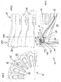
Die Betätigungsvorrichtung 95 ist radial außenseitig an einer Tragestruktur 100 angeordnet. Die Tragestruktur 100 ist stromabwärtsseitig an der Fluggasturbine 20 angeordnet und mit einer drehfesten nichtdargestellten Struktur der Fluggasturbine 20 verbunden. Die Betätigungsvorrichtung 95 umfasst einen Stellring 105 und mehrere in Umfangsrichtung verteilte Koppelelemente 110. Die Koppelelemente 110 sind steif ausgebildet. An der Tragestruktur 100 sind ferner in Umfangsrichtung in gleichmäßigem Abstand verteilte Befestigungselemente 115 radial außenseitig an der Tragestruktur 100 angeordnet. Die Tragestruktur 100 umfasst eine gestufte radial nach außen hin stromaufwärtsseitig verlaufende Ausgestaltung. Dabei ist (vgl.
Der Stellring 105 umfasst ein Ringelement 145 und ein Führungselement 150, das radial innenseitig und auf der zur Wandung 60 zugewandten Seite des Stellrings 105 angeordnet ist. Das Führungselement 150 umfasst einen senkrecht zur Drehachse 31 angeordneten ersten Führungselementabschnitt 151 und einen konusartig ausgebildeten zweiten radial innen liegend zum ersten Führungselementabschnitt 151 angeordneten zweiten Führungselementabschnitt 152. Das Führungselement 150 ist über den ersten Führungselementabschnitt 151 mit dem Ringelement 145 verbunden. An dem zweiten Führungselementabschnitt 152 ist radial innen zum Stellring 145 auf der zur Führungsfläche 140 zugewandten Seite ein V-förmig ausgebildeter Lagerabschnitt 153 vorgesehen, der auf der Führungsfläche aufliegt und den Stellring 105 radial in seiner Position festlegt bzw. lagert. Selbstverständlich ist auch denkbar, das Ringelement 145 andersartig zu lagern.The adjusting
Das Ringelement 145 umfasst mehrere erste rechteckförmig ausgebildete Aufnahmen 155, die umfangsseitig jeweils paarweise nebeneinander in gleichmäßigem Abstand angeordnet sind. In die ersten Aufnahmen 155 greift jeweils ein stromaufwärtsseitig und ein stromabwärtsseitig zum Ringelement 145 angeordnetes Koppelelement 110 ein. Das stromaufwärtsseitige Koppelelement 110 ist über die erste Aufnahme 155 mit dem Ringelement 145 an einem ersten Längsende des Koppelelements 110 und an einem zweiten Längsende des Koppelelements 110 mit dem Befestigungselement 115 verbunden. Die ersten Aufnahmen 155 umfassen jeweils zwei gegenüberliegend angeordnete erste Gelenkbolzenaufnahmen 156, die auf einer Achse 157 senkrecht zur Drehachse 31 angeordnet sind. Selbstverständlich ist auch denkbar, dass die ersten Aufnahmen 155 unregelmäßig, einzeln und/oder gruppiert entlang des Umfangs des Ringelements 145 verteilt sind. Auch ist denkbar, dass die ersten Aufnahmen 155 andersartig beispielsweise hinsichtlich ihres Querschnitts ausgebildet sind. Das Befestigungselement 115 der Tragestruktur 100 ist dabei identisch zu der ersten Aufnahme 155 ausgebildet und entlang der Tragestruktur 100 korrespondierend zu den ersten Aufnahmen 155 umfangsseitig verteilt.The
Die Wandung 60 umfasst an dem ersten Wandabschnitt 75 einen in radialer Richtung und im Wesentlichen parallel zur Drehachse 31 sich erstreckenden Gelenksteg 160, der radial außenseitig an dem ersten Wandabschnitt 75 angeordnet ist. Der Gelenksteg 160 umfast eine Gelenkbohrung 165, die stromaufwärtsseitig, radial außen liegend zu der ersten Führungskontur 85 und an diese angrenzend an dem Gelenksteg 160 angeordnet ist. Radial außen liegend zu der Gelenkbohrung 165 ist eine Koppelaufnahme 170 angeordnet, die zwei parallel sich erstreckend ausgebildete Laschenelemente 175 umfasst. In den Laschenelementen 175 ist jeweils eine zweite Gelenkbolzenaufnahme 180 vorgesehen, um einen radial in Richtung der Drehachse 31 verlaufenden ersten Gelenkbolzen 185 aufzunehmen (vgl.
Die Stege 125 sind parallel an dem ersten Abschnitt 120 der Tragestruktur 110 angeordnet und umgreifen seitlich den Gelenksteg 160 an der Gelenkbohrung 165 und liegen an einer ihnen jeweils zugewandten Seitenfläche 190 des Gelenkstegs 160 im Bereich der Gelenkbohrung 165 an. Durch die erste Gelenköffnung 130 und die Gelenkbohrung 165 ist ferner ein zweiter Gelenkbolzen 195 geführt, um ein Gelenk 196 zum Schwenken des ersten Wandabschnitts 75 um eine Schwenkachse 200, die senkrecht zur Drehachse 31 der Fluggasturbine 20 ausgerichtet ist, bereitzustellen.The
Das Koppelelement 110 umfasst an einem ersten Längsende eine zweite Aufnahme 205 und an einem zweiten Längsende eine dritte Aufnahme 210. Die zweite bzw. dritte Aufnahme 205, 210 sind dabei innenseitig kugelschalenartig ausgebildet. Zwischen den beiden Aufnahmen 205, 210 ist eine Koppelstange 215 angeordnet, die geradlinig ausgebildet ist und die zweite Aufnahme 205 mit der dritten Aufnahme 210 verbindet. Die beiden Aufnahmen 205, 210 umgreifen umfangsseitig einen Gelenkkopf 220, der außenseitig in seiner Ausgestaltung an die kugelschalenartige Ausgestaltung der zweiten Aufnahme 205 bzw. dritten Aufnahme 210 angepasst ist. Der Gelenkkopf 220 wird umfangsseitig durch die Aufnahmen 205, 210 umgriffen, wobei der Gelenkkopf 220 mit der ihm zugeordneten zweiten bzw. dritten Aufnahme 205, 210 in Berührkontakt steht um durch die jeweilige Aufnahme 205, 210 in seiner Position fixiert zu werden. Dabei bilden der Gelenkkopf 220 und die Aufnahmen 205, 210 jeweils ein Gelenk 221 aus, wobei die zweiten bzw. dritten Aufnahmen 205, 210 jeweils einen ersten Gelenkabschnitt darstellen, der gegenüber dem Gelenkkopf 220 als zweiter Gelenkabschnitt in wenigstens zwei Ebenen bzw. um die Achse 157 und eine weitere Schwenkachse 222 geneigt werden kann, die senkrecht zur Achse 157 ausgerichtet ist. Um ein ungewolltes Herausrutschen des Gelenkkopfs 220 aus der zweiten bzw. dritten Aufnahme 205, 210 zu vermeiden, kann beispielsweise der Gelenkkopf 220 in die zweite bzw. dritte Aufnahme 205, 210 eingepresst sein. Dabei ist in der Ausführungsform das Gelenk 221 als Kugelgelenk ausgebildet, wobei selbstverständlich auch andere Gelenkausbildungen denkbar wären, sofern ein Schwenken der Koppelstange 215 gegenüber dem Ringelement 145 in zwei Ebenen möglich ist.The
Der Gelenkkopf 220 umfasst eine dritte Gelenkbolzenaufnahme 225. Zur Verbindung des stromabwärtsseitig zum Ringelement 145 angeordneten Koppelelements 110 ist durch die dritte Gelenkbolzenaufnahme 225 in montiertem Zustand der Mischvorrichtung 30 der erste Gelenkbolzen 185 geführt, der ferner durch die erste Gelenkbolzenaufnahme 156 der ersten Aufnahme 155 des Ringelements 145 geführt ist und somit das Koppelelement 110 an der zweiten Aufnahme 205 mit dem Ringelement 145 verbindet.The
Durch die dritte Aufnahme 210 bzw. deren zweite Gelenkbolzenaufnahme 180 des Koppelelements 110 und die Koppelaufnahme 170 bzw. deren zweite Gelenkbolzenaufnahmen 180 ist ferner ein weiterer erster Gelenkbolzen 185 geführt, der das Koppelelement 110 mit dem Gelenksteg 160 verbindet. Auf diese Weise kann das Ringelement 145 einfach mit dem Gelenksteg 160 gekoppelt werden.By the
Das in
In der Ausführungsform sind sowohl die zweite als auch die dritte Aufnahme 205, 210 identisch zueinander ausgebildet. Selbstverständlich ist auch denkbar, dass die zweite bzw. dritte Aufnahme 205, 210 bzw. ein zu der zweiten bzw. dritten Aufnahme 205, 210 zugeordneter Gelenkkopf 220 abweichend zueinander ausgebildet sind. Ferner sind in der Ausführungsform die beiden Koppelstangen 215 in ihrer Längserstreckung identisch. Selbstverständlich ist auch eine Ausgestaltung dahingehend denkbar, dass das in den
Der Stellring 105 ist mit einem in
Wird der Stellring 105 aus einer ersten Drehposition beispielsweise gegen den Uhrzeigersinn in
Um das Eindringen des Kaltluftstroms 50 in die Mischvorrichtung 30 bzw. ein Vermischen des Heißluftstroms 40 mit dem Kaltluftstrom 50 an der Betätigungseinrichtung 95 zu vermeiden, ist die Tragestruktur 100 und deren einzelne Abschnitte 120, 135, 141 einstückig miteinander verbunden. Ferner sind die einzelnen Abschnitte 120, 135, 141 derartig zueinander gestuft angeordnet, dass die Betätigungsvorrichtung 95 vollständig stromabwärtsseitig hinter der Tragestruktur 100 angeordnet ist und so im Totwassergebiet der Tragestruktur 100 liegt. Zusätzlich ist ferner denkbar, dass an der Tragestruktur 100 ein nicht dargestelltes Dichtelement vorgesehen ist, um die Tragestruktur 100 radial nach außen hin zu einer Verkleidung 240 hin abzudichten. Die Verkleidung 240 ist in einzelnen Verkleidungssegmenten 241 ausgebildet und weist einen Überlappungsabschnitt 245 auf, mit dem sich die Verkleidung 240 mit dem zweiten Wandabschnitt 80 überlappt, so dass ein Eindringen des Kaltluftstroms 50 in die Mischvorrichtung 30 vermieden wird. Dabei ist der Überlappungsabschnitt 245 derart ausgebildet, dass in jeder der angefahrenen Position des zweiten Wandabschnitts 80 die Verkleidung 240 radial außenseitig an dem zweiten Wandabschnitt 80 anliegt. Auf diese Weise wird ferner zuverlässig eine Vermischung von Heißluftstrom 40 und Kaltluftstrom 50 innerhalb der Mischvorrichtung 30, insbesondere innerhalb der Betätigungsvorrichtung 95, vermieden.In order to avoid the penetration of the
- 1010
- TurbofantriebwerkTurbofan
- 1515
- TriebwerksgondelEngine nacelle
- 2020
- FluggasturbineAircraft gas turbine
- 2525
- Fanfan
- 3030
- Mischvorrichtungmixing device
- 3131
- Drehachseaxis of rotation
- 3535
- Strömungsteilerflow divider
- 4040
- HeißluftstromHot air stream
- 4545
- Abgaskonusexhaust cone
- 5050
- KaltluftstromCold air flow
- 5555
- Innenwandinner wall
- 6060
- Wandungwall
- 6161
- MischebeneLayers,
- 6565
- erster Kanalfirst channel
- 7070
- zweiter Kanalsecond channel
- 7575
- erster Wandabschnittfirst wall section
- 8080
- zweiter Wandabschnittsecond wall section
- 8585
- erste Führungskonturfirst guide contour
- 9090
- zweite Führungskontursecond guide contour
- 9595
- Betätigungsvorrichtungactuator
- 100100
- Tragestruktursupport structure
- 105105
- Stellringcollar
- 110110
- Koppelelementcoupling element
- 115115
- Befestigungselementfastener
- 120120
- erster radial innen liegender Abschnitt der Tragestrukturfirst radially inner portion of the support structure
- 125125
- Stegweb
- 130130
- erste Gelenköffnungfirst joint opening
- 135135
- zweiter Abschnitt der Tragestruktursecond section of the support structure
- 136136
- erster Verbindungsstegfirst connecting bridge
- 140140
- Führungsflächeguide surface
- 141141
- dritter Abschnitt der Tragestrukturthird section of the support structure
- 142142
- zweiter Verbindungsstegsecond connecting bridge
- 145145
- Ringelementring element
- 150150
- Führungselementguide element
- 151151
- FührungselementabschnittGuide element portion
- 152152
- FührungselementabschnittGuide element portion
- 153153
- Lagerabschnittbearing section
- 155155
- Aufnahmeadmission
- 156156
- erste Gelenkbolzenaufnahmefirst hinge pin receptacle
- 157157
- Achseaxis
- 160160
- Gelenksteghinge web
- 165165
- Gelenkbohrungpivotal hole
- 170170
- KoppelaufnahmeKoppel recording
- 175175
- Laschenelementtab member
- 180180
- zweite Gelenkbolzenaufnahmesecond hinge pin receptacle
- 185185
- Gelenkbolzenhinge pins
- 190190
- Seitenflächeside surface
- 195195
- zweiter Gelenkbolzensecond hinge pin
- 196196
- Gelenkjoint
- 200200
- Schwenkachseswivel axis
- 205205
- zweite Aufnahmesecond shot
- 210210
- dritte Aufnahmethird recording
- 215215
- Koppelstangecoupling rod
- 220220
- Gelenkkopfjoint head
- 221221
- Gelenkjoint
- 225225
- dritte Gelenkbolzenaufnahmethird hinge pin receptacle
- 235235
- Aktuatoractuator
- 240240
- Verkleidungpaneling
- 241241
- Verkleidungssegmentface segment
- 245245
- Überlappungsabschnittoverlapping portion
Claims (9)
- A mixing device (30) for mixing a first gas flow (40) with a second gas flow (50) in a turbofan engine (20),- having an actuating device (95) and a wall (60) which delimits a radially internal channel (65) for the first gas flow (40) and a radially external channel (70) for the second gas flow (50),- wherein the actuating device (95) comprises a coupling element (110) which is coupled to the wall (60),- wherein the actuating device (95) is formed to swivel the wall (60), by means of the coupling element (110), between a first position and a second position arranged radially externally relative to the first position,- wherein the actuating device (95) comprises an adjusting ring (105) that is connected to the coupling element (110) and can be rotated between a first rotary position and a second rotary position in the circumferential direction,- wherein the coupling element (110) is formed rigidly and is coupled to the adjusting ring (105) in such a way that as a result of a rotation of the adjusting ring (105) between the first rotary position and the second rotary position the wall (60) is swivelled, by means of the coupling element (110), between the first position and the second position in a manner corresponding to the rotation of the adjusting ring (105),characterised by a supporting structure (100) that is arranged in the axial direction adjacently to the wall (60), wherein the supporting structure (100) comprises a securing element (115), wherein axially the adjusting ring (105) is arranged between the securing element (115) and the wall (60) and is connected with a further coupling element (110) to the securing element (115).
- A mixing device (30) according to claim 1, characterised in that the coupling element (110) and the further coupling element (110) are arranged next to one another in the circumferential direction adjacently to the adjusting ring (105).
- A mixing device (30) according to one of the preceding claims, characterised in that the coupling element (110) comprises a coupling rod (215), and at least one articulation (221) is provided having a first articulation section (205, 210) and a second articulation section (220) connected to the first articulation section (205, 210), wherein the first articulation section (205, 210) can be swivelled with respect to the second articulation section (220) about at least one axis (157, 222), in particular two axes (157, 222), wherein the first articulation section (205, 210) is arranged at at least one longitudinal end of the coupling rod (215), and wherein the second articulation section (220) is coupled to the securing element (115) or the adjusting ring (105) or the wall (60).
- A mixing device (30) according to claim 2 or 3, characterised in that the coupling element (110) and the further coupling element (110) are identically formed.
- A mixing device (30) according to one of claims 2 or 3, characterised in that the coupling element (110) has a longitudinal extension that differs from a longitudinal extension of the further coupling element (110).
- A mixing device (30) according to one of the preceding claims, characterised in that the wall (60) comprises a first wall section (75) and a second wall section (80) that is arranged radially externally relative to the first wall section (75), wherein the coupling element (110) is connected to the first wall section (75), and wherein the second wall section (80) is coupled to the first wall section (75).
- 11 mixing device (30) according to claim 6, characterised in that arranged on the supporting structure (100) there is a further articulation (196) which connects the first wall section (75), in a manner such that it can be swivelled about a swivel axes (200), to the supporting structure (100), wherein the swivel axis (200) of the articulation (196) is arranged perpendicularly to a rotational axis (31) of the adjusting ring (105).
- A mixing device (30) according to claim 7, characterised in that arranged on the first wall section (75) externally there is an articulation web (160), wherein on the articulation web (160) radially externally at a distance from the swivel axis (200) the coupling element (110) is connected to the articulation web (160).
- A turbofan engine (20) having a fan (25), an aircraft gas turbine (20), coupled to the fan (25), and a mixing device (30), wherein the aircraft gas turbine (20) is formed to provide a first gas flow (40), and the fan (25) is formed to provide a second gas flow (50) flowing radially externally relative to the first gas flow (40), wherein the mixing device (30) is arranged downstream of the aircraft gas turbine (20) and is formed to mix the first gas flow (40) with the second gas flow (50) at least in part, characterised in that the mixing device (30) is formed according to one of the preceding claims.
Applications Claiming Priority (1)
| Application Number | Priority Date | Filing Date | Title |
|---|---|---|---|
| DE102013205911.6A DE102013205911A1 (en) | 2013-04-04 | 2013-04-04 | Mixing device and turbofan engine with such a mixing device |
Publications (2)
| Publication Number | Publication Date |
|---|---|
| EP2787210A1 EP2787210A1 (en) | 2014-10-08 |
| EP2787210B1 true EP2787210B1 (en) | 2015-10-14 |
Family
ID=50439211
Family Applications (1)
| Application Number | Title | Priority Date | Filing Date |
|---|---|---|---|
| EP14163289.3A Not-in-force EP2787210B1 (en) | 2013-04-04 | 2014-04-03 | Mixing device and turbofan engine with such a mixing device |
Country Status (3)
| Country | Link |
|---|---|
| US (1) | US9771896B2 (en) |
| EP (1) | EP2787210B1 (en) |
| DE (1) | DE102013205911A1 (en) |
Families Citing this family (2)
| Publication number | Priority date | Publication date | Assignee | Title |
|---|---|---|---|---|
| FR2994712B1 (en) * | 2012-08-27 | 2018-04-13 | Safran Aircraft Engines | METHOD FOR ASSEMBLING A TUBE AND AN EXHAUST HOUSING OF A TURBOMACHINE |
| US10082043B2 (en) | 2015-06-25 | 2018-09-25 | Pratt & Whitney Canada Corp. | Segmented multi-lobe mixer |
Family Cites Families (9)
| Publication number | Priority date | Publication date | Assignee | Title |
|---|---|---|---|---|
| GB1002116A (en) * | 1964-04-24 | 1965-08-25 | Rolls Royce | Fluid flow control apparatus |
| FR1405358A (en) * | 1964-05-27 | 1965-07-09 | Nord Aviation | Method and device for rapid mixing of fluids, in particular on a combined turbostatorjet |
| US3556246A (en) * | 1969-06-16 | 1971-01-19 | Rohr Corp | Method and apparatus for suppressing the noise of a fan jet engine |
| US5372006A (en) * | 1993-02-08 | 1994-12-13 | Aeronautical Concept Of Exhaust, Ltd. | Turbine engine equipped with thrust reverser |
| US5771681A (en) * | 1996-09-17 | 1998-06-30 | The Boeing Company | Aircraft turbofan engine mixing apparatus |
| EP1052395B1 (en) * | 1999-05-13 | 2004-07-07 | Industria de Turbo Propulsores S.A. | Exit area control mechanism for convergent divergent nozzles |
| US6966175B2 (en) * | 2003-05-09 | 2005-11-22 | The Nordam Group, Inc. | Rotary adjustable exhaust nozzle |
| DE102010014909A1 (en) | 2010-04-14 | 2011-10-20 | Rolls-Royce Deutschland Ltd & Co Kg | Variable mixer i.e. variable bloom mixer, for mixing cool and hot air streams of fan of turbofan engine of aircraft, has traction cable for obtaining original position by compensating traction force using resilient material properties |
| DE102010014910A1 (en) | 2010-04-14 | 2011-10-20 | Rolls-Royce Deutschland Ltd & Co Kg | Mixing device for turbofan engine for mixing cold air stream with hot-air stream, has engine pod and exhaust cone that defines cold air stream with hot-air stream |
-
2013
- 2013-04-04 DE DE102013205911.6A patent/DE102013205911A1/en not_active Withdrawn
-
2014
- 2014-04-03 EP EP14163289.3A patent/EP2787210B1/en not_active Not-in-force
- 2014-04-03 US US14/244,050 patent/US9771896B2/en not_active Expired - Fee Related
Also Published As
| Publication number | Publication date |
|---|---|
| DE102013205911A1 (en) | 2014-10-09 |
| US20140298772A1 (en) | 2014-10-09 |
| EP2787210A1 (en) | 2014-10-08 |
| US9771896B2 (en) | 2017-09-26 |
Similar Documents
| Publication | Publication Date | Title |
|---|---|---|
| EP2960437B1 (en) | Variable guide vane device for a gas turbine and gas turbine equipped with such a device | |
| EP2769147A1 (en) | Fuel nozzle for two fuels | |
| EP3330490B1 (en) | Turbo machines seal arrangement | |
| DE2815573A1 (en) | EXHAUST GAS NOZZLE WITH VARIABLE THROUGH-SECTION FOR GAS TURBINES AND LEVER GEAR ARRANGEMENT FOR SUCH AN EXHAUST GAS NOZZLE | |
| DE60313893T2 (en) | DRAINING DEVICE WITH OPTIMIZED RADIATION GRILLE | |
| EP2989298B1 (en) | Exhaust gas turbocharger | |
| CH703871B1 (en) | Verstellleitapparatanordnung for a compressor. | |
| EP1984601A1 (en) | Turbocharger comprising adjustable guide blades, blade lever and adjusting ring therefor | |
| DE102012106888B4 (en) | Exhaust flap assembly with integrated bypass | |
| WO2013127664A1 (en) | Exhaust gas turbocharger having guiding screen rings that are rotatable relative to each other | |
| DE102015004649A1 (en) | Guide vane adjusting device and turbomachine | |
| WO2019121022A1 (en) | Propelling nozzle for a turbofan engine on a supersonic aircraft | |
| DE112012002909T5 (en) | turbocharger | |
| EP3009683A1 (en) | Device and method for bleeding compressor air in an engine | |
| EP2787210B1 (en) | Mixing device and turbofan engine with such a mixing device | |
| DE112014005008T5 (en) | Turbine with variable inlet cross-sectional area | |
| EP2592258B1 (en) | Exhaust gas recirculation valve | |
| DE2834860A1 (en) | ADJUSTABLE FLOW DIVIDER FOR FLOW MACHINES, ESPECIALLY GAS TURBINE JET ENGINES | |
| EP2020544B1 (en) | Valve, in particular waste gas refeeding valve | |
| EP3081788B1 (en) | Exhaust outlet with a control valve | |
| DE102017129359A1 (en) | Arrangement with a press, with two components and with at least one clamping element | |
| EP2225467B1 (en) | Swirl-generating apparatus and turbocharger with such a swirl-generating apparatus | |
| EP2696042A1 (en) | Fluid flow engine with at least one guide blade assembly | |
| EP2496505B1 (en) | Device for handling value notes | |
| EP3366908A1 (en) | Convergent-divergent nozzle for a turbofan engine of a supersonic aircraft |
Legal Events
| Date | Code | Title | Description |
|---|---|---|---|
| PUAI | Public reference made under article 153(3) epc to a published international application that has entered the european phase |
Free format text: ORIGINAL CODE: 0009012 |
|
| 17P | Request for examination filed |
Effective date: 20140403 |
|
| AK | Designated contracting states |
Kind code of ref document: A1 Designated state(s): AL AT BE BG CH CY CZ DE DK EE ES FI FR GB GR HR HU IE IS IT LI LT LU LV MC MK MT NL NO PL PT RO RS SE SI SK SM TR |
|
| AX | Request for extension of the european patent |
Extension state: BA ME |
|
| R17P | Request for examination filed (corrected) |
Effective date: 20150309 |
|
| RBV | Designated contracting states (corrected) |
Designated state(s): AL AT BE BG CH CY CZ DE DK EE ES FI FR GB GR HR HU IE IS IT LI LT LU LV MC MK MT NL NO PL PT RO RS SE SI SK SM TR |
|
| REG | Reference to a national code |
Ref country code: DE Ref legal event code: R079 Ref document number: 502014000139 Country of ref document: DE Free format text: PREVIOUS MAIN CLASS: F02K0001380000 Ipc: F02K0003075000 |
|
| GRAP | Despatch of communication of intention to grant a patent |
Free format text: ORIGINAL CODE: EPIDOSNIGR1 |
|
| INTG | Intention to grant announced |
Effective date: 20150716 |
|
| RIC1 | Information provided on ipc code assigned before grant |
Ipc: F02K 1/38 20060101ALI20150707BHEP Ipc: F02K 3/075 20060101AFI20150707BHEP |
|
| GRAS | Grant fee paid |
Free format text: ORIGINAL CODE: EPIDOSNIGR3 |
|
| GRAA | (expected) grant |
Free format text: ORIGINAL CODE: 0009210 |
|
| AK | Designated contracting states |
Kind code of ref document: B1 Designated state(s): AL AT BE BG CH CY CZ DE DK EE ES FI FR GB GR HR HU IE IS IT LI LT LU LV MC MK MT NL NO PL PT RO RS SE SI SK SM TR |
|
| REG | Reference to a national code |
Ref country code: GB Ref legal event code: FG4D Free format text: NOT ENGLISH |
|
| REG | Reference to a national code |
Ref country code: AT Ref legal event code: REF Ref document number: 755305 Country of ref document: AT Kind code of ref document: T Effective date: 20151015 Ref country code: CH Ref legal event code: EP |
|
| REG | Reference to a national code |
Ref country code: NL Ref legal event code: MP Effective date: 20151014 |
|
| REG | Reference to a national code |
Ref country code: IE Ref legal event code: FG4D Free format text: LANGUAGE OF EP DOCUMENT: GERMAN |
|
| REG | Reference to a national code |
Ref country code: DE Ref legal event code: R096 Ref document number: 502014000139 Country of ref document: DE |
|
| REG | Reference to a national code |
Ref country code: LT Ref legal event code: MG4D |
|
| REG | Reference to a national code |
Ref country code: FR Ref legal event code: PLFP Year of fee payment: 3 |
|
| PG25 | Lapsed in a contracting state [announced via postgrant information from national office to epo] |
Ref country code: LT Free format text: LAPSE BECAUSE OF FAILURE TO SUBMIT A TRANSLATION OF THE DESCRIPTION OR TO PAY THE FEE WITHIN THE PRESCRIBED TIME-LIMIT Effective date: 20151014 Ref country code: NO Free format text: LAPSE BECAUSE OF FAILURE TO SUBMIT A TRANSLATION OF THE DESCRIPTION OR TO PAY THE FEE WITHIN THE PRESCRIBED TIME-LIMIT Effective date: 20160114 Ref country code: NL Free format text: LAPSE BECAUSE OF FAILURE TO SUBMIT A TRANSLATION OF THE DESCRIPTION OR TO PAY THE FEE WITHIN THE PRESCRIBED TIME-LIMIT Effective date: 20151014 Ref country code: IT Free format text: LAPSE BECAUSE OF FAILURE TO SUBMIT A TRANSLATION OF THE DESCRIPTION OR TO PAY THE FEE WITHIN THE PRESCRIBED TIME-LIMIT Effective date: 20151014 Ref country code: ES Free format text: LAPSE BECAUSE OF FAILURE TO SUBMIT A TRANSLATION OF THE DESCRIPTION OR TO PAY THE FEE WITHIN THE PRESCRIBED TIME-LIMIT Effective date: 20151014 Ref country code: IS Free format text: LAPSE BECAUSE OF FAILURE TO SUBMIT A TRANSLATION OF THE DESCRIPTION OR TO PAY THE FEE WITHIN THE PRESCRIBED TIME-LIMIT Effective date: 20160214 Ref country code: HR Free format text: LAPSE BECAUSE OF FAILURE TO SUBMIT A TRANSLATION OF THE DESCRIPTION OR TO PAY THE FEE WITHIN THE PRESCRIBED TIME-LIMIT Effective date: 20151014 |
|
| PG25 | Lapsed in a contracting state [announced via postgrant information from national office to epo] |
Ref country code: PT Free format text: LAPSE BECAUSE OF FAILURE TO SUBMIT A TRANSLATION OF THE DESCRIPTION OR TO PAY THE FEE WITHIN THE PRESCRIBED TIME-LIMIT Effective date: 20160215 Ref country code: PL Free format text: LAPSE BECAUSE OF FAILURE TO SUBMIT A TRANSLATION OF THE DESCRIPTION OR TO PAY THE FEE WITHIN THE PRESCRIBED TIME-LIMIT Effective date: 20151014 Ref country code: SE Free format text: LAPSE BECAUSE OF FAILURE TO SUBMIT A TRANSLATION OF THE DESCRIPTION OR TO PAY THE FEE WITHIN THE PRESCRIBED TIME-LIMIT Effective date: 20151014 Ref country code: GR Free format text: LAPSE BECAUSE OF FAILURE TO SUBMIT A TRANSLATION OF THE DESCRIPTION OR TO PAY THE FEE WITHIN THE PRESCRIBED TIME-LIMIT Effective date: 20160115 Ref country code: LV Free format text: LAPSE BECAUSE OF FAILURE TO SUBMIT A TRANSLATION OF THE DESCRIPTION OR TO PAY THE FEE WITHIN THE PRESCRIBED TIME-LIMIT Effective date: 20151014 Ref country code: FI Free format text: LAPSE BECAUSE OF FAILURE TO SUBMIT A TRANSLATION OF THE DESCRIPTION OR TO PAY THE FEE WITHIN THE PRESCRIBED TIME-LIMIT Effective date: 20151014 Ref country code: RS Free format text: LAPSE BECAUSE OF FAILURE TO SUBMIT A TRANSLATION OF THE DESCRIPTION OR TO PAY THE FEE WITHIN THE PRESCRIBED TIME-LIMIT Effective date: 20151014 |
|
| REG | Reference to a national code |
Ref country code: DE Ref legal event code: R097 Ref document number: 502014000139 Country of ref document: DE |
|
| PG25 | Lapsed in a contracting state [announced via postgrant information from national office to epo] |
Ref country code: CZ Free format text: LAPSE BECAUSE OF FAILURE TO SUBMIT A TRANSLATION OF THE DESCRIPTION OR TO PAY THE FEE WITHIN THE PRESCRIBED TIME-LIMIT Effective date: 20151014 |
|
| PLBE | No opposition filed within time limit |
Free format text: ORIGINAL CODE: 0009261 |
|
| STAA | Information on the status of an ep patent application or granted ep patent |
Free format text: STATUS: NO OPPOSITION FILED WITHIN TIME LIMIT |
|
| PG25 | Lapsed in a contracting state [announced via postgrant information from national office to epo] |
Ref country code: DK Free format text: LAPSE BECAUSE OF FAILURE TO SUBMIT A TRANSLATION OF THE DESCRIPTION OR TO PAY THE FEE WITHIN THE PRESCRIBED TIME-LIMIT Effective date: 20151014 Ref country code: BE Free format text: LAPSE BECAUSE OF NON-PAYMENT OF DUE FEES Effective date: 20160430 Ref country code: RO Free format text: LAPSE BECAUSE OF FAILURE TO SUBMIT A TRANSLATION OF THE DESCRIPTION OR TO PAY THE FEE WITHIN THE PRESCRIBED TIME-LIMIT Effective date: 20151014 Ref country code: SK Free format text: LAPSE BECAUSE OF FAILURE TO SUBMIT A TRANSLATION OF THE DESCRIPTION OR TO PAY THE FEE WITHIN THE PRESCRIBED TIME-LIMIT Effective date: 20151014 Ref country code: SM Free format text: LAPSE BECAUSE OF FAILURE TO SUBMIT A TRANSLATION OF THE DESCRIPTION OR TO PAY THE FEE WITHIN THE PRESCRIBED TIME-LIMIT Effective date: 20151014 Ref country code: EE Free format text: LAPSE BECAUSE OF FAILURE TO SUBMIT A TRANSLATION OF THE DESCRIPTION OR TO PAY THE FEE WITHIN THE PRESCRIBED TIME-LIMIT Effective date: 20151014 |
|
| 26N | No opposition filed |
Effective date: 20160715 |
|
| PG25 | Lapsed in a contracting state [announced via postgrant information from national office to epo] |
Ref country code: SI Free format text: LAPSE BECAUSE OF FAILURE TO SUBMIT A TRANSLATION OF THE DESCRIPTION OR TO PAY THE FEE WITHIN THE PRESCRIBED TIME-LIMIT Effective date: 20151014 |
|
| PG25 | Lapsed in a contracting state [announced via postgrant information from national office to epo] |
Ref country code: LU Free format text: LAPSE BECAUSE OF FAILURE TO SUBMIT A TRANSLATION OF THE DESCRIPTION OR TO PAY THE FEE WITHIN THE PRESCRIBED TIME-LIMIT Effective date: 20160403 |
|
| REG | Reference to a national code |
Ref country code: IE Ref legal event code: MM4A |
|
| REG | Reference to a national code |
Ref country code: FR Ref legal event code: PLFP Year of fee payment: 4 |
|
| PG25 | Lapsed in a contracting state [announced via postgrant information from national office to epo] |
Ref country code: IE Free format text: LAPSE BECAUSE OF NON-PAYMENT OF DUE FEES Effective date: 20160403 |
|
| REG | Reference to a national code |
Ref country code: CH Ref legal event code: PL |
|
| PG25 | Lapsed in a contracting state [announced via postgrant information from national office to epo] |
Ref country code: CH Free format text: LAPSE BECAUSE OF NON-PAYMENT OF DUE FEES Effective date: 20170430 Ref country code: LI Free format text: LAPSE BECAUSE OF NON-PAYMENT OF DUE FEES Effective date: 20170430 |
|
| REG | Reference to a national code |
Ref country code: FR Ref legal event code: PLFP Year of fee payment: 5 |
|
| PG25 | Lapsed in a contracting state [announced via postgrant information from national office to epo] |
Ref country code: HU Free format text: LAPSE BECAUSE OF FAILURE TO SUBMIT A TRANSLATION OF THE DESCRIPTION OR TO PAY THE FEE WITHIN THE PRESCRIBED TIME-LIMIT; INVALID AB INITIO Effective date: 20140403 |
|
| PG25 | Lapsed in a contracting state [announced via postgrant information from national office to epo] |
Ref country code: CY Free format text: LAPSE BECAUSE OF FAILURE TO SUBMIT A TRANSLATION OF THE DESCRIPTION OR TO PAY THE FEE WITHIN THE PRESCRIBED TIME-LIMIT Effective date: 20151014 Ref country code: MK Free format text: LAPSE BECAUSE OF FAILURE TO SUBMIT A TRANSLATION OF THE DESCRIPTION OR TO PAY THE FEE WITHIN THE PRESCRIBED TIME-LIMIT Effective date: 20151014 Ref country code: MC Free format text: LAPSE BECAUSE OF FAILURE TO SUBMIT A TRANSLATION OF THE DESCRIPTION OR TO PAY THE FEE WITHIN THE PRESCRIBED TIME-LIMIT Effective date: 20151014 Ref country code: MT Free format text: LAPSE BECAUSE OF FAILURE TO SUBMIT A TRANSLATION OF THE DESCRIPTION OR TO PAY THE FEE WITHIN THE PRESCRIBED TIME-LIMIT Effective date: 20151014 |
|
| PG25 | Lapsed in a contracting state [announced via postgrant information from national office to epo] |
Ref country code: BG Free format text: LAPSE BECAUSE OF FAILURE TO SUBMIT A TRANSLATION OF THE DESCRIPTION OR TO PAY THE FEE WITHIN THE PRESCRIBED TIME-LIMIT Effective date: 20151014 |
|
| PG25 | Lapsed in a contracting state [announced via postgrant information from national office to epo] |
Ref country code: TR Free format text: LAPSE BECAUSE OF FAILURE TO SUBMIT A TRANSLATION OF THE DESCRIPTION OR TO PAY THE FEE WITHIN THE PRESCRIBED TIME-LIMIT Effective date: 20151014 Ref country code: AL Free format text: LAPSE BECAUSE OF FAILURE TO SUBMIT A TRANSLATION OF THE DESCRIPTION OR TO PAY THE FEE WITHIN THE PRESCRIBED TIME-LIMIT Effective date: 20151014 |
|
| PGFP | Annual fee paid to national office [announced via postgrant information from national office to epo] |
Ref country code: DE Payment date: 20190418 Year of fee payment: 6 |
|
| PGFP | Annual fee paid to national office [announced via postgrant information from national office to epo] |
Ref country code: FR Payment date: 20190423 Year of fee payment: 6 |
|
| PGFP | Annual fee paid to national office [announced via postgrant information from national office to epo] |
Ref country code: GB Payment date: 20190424 Year of fee payment: 6 |
|
| REG | Reference to a national code |
Ref country code: AT Ref legal event code: MM01 Ref document number: 755305 Country of ref document: AT Kind code of ref document: T Effective date: 20190403 |
|
| REG | Reference to a national code |
Ref country code: DE Ref legal event code: R119 Ref document number: 502014000139 Country of ref document: DE |
|
| PG25 | Lapsed in a contracting state [announced via postgrant information from national office to epo] |
Ref country code: AT Free format text: LAPSE BECAUSE OF NON-PAYMENT OF DUE FEES Effective date: 20190403 |
|
| PG25 | Lapsed in a contracting state [announced via postgrant information from national office to epo] |
Ref country code: DE Free format text: LAPSE BECAUSE OF NON-PAYMENT OF DUE FEES Effective date: 20201103 Ref country code: FR Free format text: LAPSE BECAUSE OF NON-PAYMENT OF DUE FEES Effective date: 20200430 |
|
| GBPC | Gb: european patent ceased through non-payment of renewal fee |
Effective date: 20200403 |
|
| PG25 | Lapsed in a contracting state [announced via postgrant information from national office to epo] |
Ref country code: GB Free format text: LAPSE BECAUSE OF NON-PAYMENT OF DUE FEES Effective date: 20200403 |