EP2787128A1 - Hydraulic line fixing apparatus for boom swing-type excavators - Google Patents
Hydraulic line fixing apparatus for boom swing-type excavators Download PDFInfo
- Publication number
- EP2787128A1 EP2787128A1 EP11876817.5A EP11876817A EP2787128A1 EP 2787128 A1 EP2787128 A1 EP 2787128A1 EP 11876817 A EP11876817 A EP 11876817A EP 2787128 A1 EP2787128 A1 EP 2787128A1
- Authority
- EP
- European Patent Office
- Prior art keywords
- boom
- hydraulic hoses
- hydraulic
- attachments
- supporter
- Prior art date
- Legal status (The legal status is an assumption and is not a legal conclusion. Google has not performed a legal analysis and makes no representation as to the accuracy of the status listed.)
- Withdrawn
Links
- 239000012530 fluid Substances 0.000 claims abstract description 10
- 238000005452 bending Methods 0.000 claims description 10
- 238000000605 extraction Methods 0.000 description 2
- 238000010276 construction Methods 0.000 description 1
- 230000008602 contraction Effects 0.000 description 1
- 230000000694 effects Effects 0.000 description 1
- 238000005516 engineering process Methods 0.000 description 1
- 239000002184 metal Substances 0.000 description 1
- 230000007935 neutral effect Effects 0.000 description 1
- 230000003287 optical effect Effects 0.000 description 1
Images




Classifications
-
- E—FIXED CONSTRUCTIONS
- E02—HYDRAULIC ENGINEERING; FOUNDATIONS; SOIL SHIFTING
- E02F—DREDGING; SOIL-SHIFTING
- E02F9/00—Component parts of dredgers or soil-shifting machines, not restricted to one of the kinds covered by groups E02F3/00 - E02F7/00
- E02F9/20—Drives; Control devices
- E02F9/22—Hydraulic or pneumatic drives
- E02F9/2264—Arrangements or adaptations of elements for hydraulic drives
- E02F9/2275—Hoses and supports therefor and protection therefor
-
- E—FIXED CONSTRUCTIONS
- E02—HYDRAULIC ENGINEERING; FOUNDATIONS; SOIL SHIFTING
- E02F—DREDGING; SOIL-SHIFTING
- E02F3/00—Dredgers; Soil-shifting machines
- E02F3/04—Dredgers; Soil-shifting machines mechanically-driven
- E02F3/28—Dredgers; Soil-shifting machines mechanically-driven with digging tools mounted on a dipper- or bucket-arm, i.e. there is either one arm or a pair of arms, e.g. dippers, buckets
- E02F3/36—Component parts
- E02F3/38—Cantilever beams, i.e. booms;, e.g. manufacturing processes, forms, geometry or materials used for booms; Dipper-arms, e.g. manufacturing processes, forms, geometry or materials used for dipper-arms; Bucket-arms
- E02F3/382—Connections to the frame; Supports for booms or arms
- E02F3/384—Connections to the frame; Supports for booms or arms the boom being pivotable relative to the frame about a vertical axis
-
- F—MECHANICAL ENGINEERING; LIGHTING; HEATING; WEAPONS; BLASTING
- F16—ENGINEERING ELEMENTS AND UNITS; GENERAL MEASURES FOR PRODUCING AND MAINTAINING EFFECTIVE FUNCTIONING OF MACHINES OR INSTALLATIONS; THERMAL INSULATION IN GENERAL
- F16L—PIPES; JOINTS OR FITTINGS FOR PIPES; SUPPORTS FOR PIPES, CABLES OR PROTECTIVE TUBING; MEANS FOR THERMAL INSULATION IN GENERAL
- F16L3/00—Supports for pipes, cables or protective tubing, e.g. hangers, holders, clamps, cleats, clips, brackets
- F16L3/01—Supports for pipes, cables or protective tubing, e.g. hangers, holders, clamps, cleats, clips, brackets for supporting or guiding the pipes, cables or protective tubing, between relatively movable points, e.g. movable channels
-
- F—MECHANICAL ENGINEERING; LIGHTING; HEATING; WEAPONS; BLASTING
- F16—ENGINEERING ELEMENTS AND UNITS; GENERAL MEASURES FOR PRODUCING AND MAINTAINING EFFECTIVE FUNCTIONING OF MACHINES OR INSTALLATIONS; THERMAL INSULATION IN GENERAL
- F16L—PIPES; JOINTS OR FITTINGS FOR PIPES; SUPPORTS FOR PIPES, CABLES OR PROTECTIVE TUBING; MEANS FOR THERMAL INSULATION IN GENERAL
- F16L3/00—Supports for pipes, cables or protective tubing, e.g. hangers, holders, clamps, cleats, clips, brackets
- F16L3/22—Supports for pipes, cables or protective tubing, e.g. hangers, holders, clamps, cleats, clips, brackets specially adapted for supporting a number of parallel pipes at intervals
-
- F—MECHANICAL ENGINEERING; LIGHTING; HEATING; WEAPONS; BLASTING
- F16—ENGINEERING ELEMENTS AND UNITS; GENERAL MEASURES FOR PRODUCING AND MAINTAINING EFFECTIVE FUNCTIONING OF MACHINES OR INSTALLATIONS; THERMAL INSULATION IN GENERAL
- F16L—PIPES; JOINTS OR FITTINGS FOR PIPES; SUPPORTS FOR PIPES, CABLES OR PROTECTIVE TUBING; MEANS FOR THERMAL INSULATION IN GENERAL
- F16L3/00—Supports for pipes, cables or protective tubing, e.g. hangers, holders, clamps, cleats, clips, brackets
- F16L3/22—Supports for pipes, cables or protective tubing, e.g. hangers, holders, clamps, cleats, clips, brackets specially adapted for supporting a number of parallel pipes at intervals
- F16L3/223—Supports for pipes, cables or protective tubing, e.g. hangers, holders, clamps, cleats, clips, brackets specially adapted for supporting a number of parallel pipes at intervals each support having one transverse base for supporting the pipes
Definitions
- the present invention relates to a hydraulic pipe fixing apparatus for a boom-swing type excavator. More particularly, the present invention relates to a hydraulic pipe fixing apparatus for a boom-swing type excavator in which a boom supporter is mounted on a front end portion of an upper frame to swing, which makes hydraulic hoses for attachments, such as an arm, and hydraulic hoses for additional option devices, such as a rotator, be arranged in predetermined positions inside a boom supporter, and thus can improve the workability to arrange and assemble the hydraulic hoses for attachment and option devices.
- a hydraulic pipe fixing device for a boom-swing type excavator in the related art includes a boom supporter 4 mounted on a front end portion of an upper frame 1 to swing by an upper pin 2 and a lower pin 3; a boom 6 and a boom cylinder 7 rotatably mounted on the boom supporter 4 by fixing pins 5 and 5a; a boom swing cylinder 8 having one end that is fixed to the upper frame 1 and the other end that is mounted on the boom supporter 4 to be driven to make the boom supporter 4 swing about the upper pin 2 and the lower pin 3 as center shafts; hydraulic hoses 9 for attachments supplying hydraulic fluid from a main control valve (not illustrated) MCV that is mounted on the upper frame 1 to an arm cylinder (not illustrated); and hydraulic hoses 10 for option devices supplying the hydraulic fluid to the option devices, such as quick fit, 2pcs boom, and hammer.
- the hydraulic hose 10 for option devices is arranged on a side surface of the boom supporter 4 in an exposed state, and the hydraulic hose 9 for attachments is arranged to pass through a space between the upper pin 2 and the lower pin 3. Due to this, in the case where various kinds of option devices, such as a hammer, required by equipment users are added, it is difficult to arrange and assemble the hydraulic hoses for supplying the hydraulic fluid to the option devices with respect to the boom supporter 4 to lower the workability.
- the hydraulic hoses 9 and 10 are twisted and their bending radius becomes large according to the swing radius of the boom 6. In this case, due to frequent frictional contact with surrounding components, the hydraulic hoses 9 and 10 may be damaged. That is, due to repeated swing operations of the boom 6, external alignment states of the hydraulic hoses 9 and 10 become inferior as the hydraulic hoses 9 and 10 are twisted or bent, and this may cause the damage of the equipment in a short operation time.
- one embodiment of the present invention is related to a hydraulic pipe fixing device for a boom-swing type excavator, which can maintain good external appearance states of hydraulic hoses according to additional option devices through arrangement of the hydraulic hoses for attachments and option devices at predetermined positions of a clamp mounted therein via a lower end portion of a boom supporter, and can prevent damage of the hydraulic hoses even in the case where the boom swings at the maximum angle through securing of a larger hose bending radius of the hydraulic hoses.
- One embodiment of the present invention is related to a hydraulic pipe fixing device for a boom-swing type excavator, which can arrange corresponding hydraulic hoses at predetermined positions of a boom supporter even in the case where various kinds of option devices are added, and thus can mount the option devices having the specification required by equipment users.
- One embodiment of the present invention is related to a hydraulic pipe fixing device for a boom-swing type excavator, which can improve workability in repair and assembling through pressing of hydraulic hoses by a cover for fixing the hydraulic hoses having two-stage fastening portion in the case where the hydraulic hoses are arranged at upper and lower predetermined positions of a clamp that is fixed in a boom supporter.
- a hydraulic pipe fixing apparatus for a boom-swing type excavator, having an upper frame mounted on a lower traveling structure, a boom supporter mounted on a front end portion of the upper frame to swing and provided with a boom and a boom cylinder mounted thereon, and a boom swing cylinder making the boom supporter swing against the upper frame
- the hydraulic pipe fixing apparatus includes a clamp on which seating grooves for seating hydraulic hoses for attachments and hydraulic hoses for option devices are formed so as to arrange the hydraulic hoses for the attachments including the boom and the hydraulic hoses for the additional option devices in predetermined positions inside the boom supporter; and a cover for fixing the hydraulic hoses that is detachably fixed to the clamp by a fastening member so as to prevent the hydraulic hoses from seceding from the seating grooves and to intercept mutual contact of a boom cylinder fixing member and the hydraulic hoses for the attachments and the option devices that move toward the boom cylinder side when hydraulic fluid is supplied to the hydraulic pipe fixing apparatus
- the cover for fixing the hydraulic hoses has assembling holes formed thereon and composed of a first through-hole into which a head portion of the fastening member is fitted and a second through-hole formed to communicate with the first through-hole with a size that is relatively smaller than the size of the first through-hole.
- the hydraulic pipe fixing apparatus further includes a cover for protecting the hydraulic hoses that is detachably fixed to a bottom portion of the boom supporter by the fastening member to protect the hydraulic hoses for the attachments and the option devices that are exposed to the bottom of the boom supporter from external impact.
- the hydraulic hoses for the attachments and the hydraulic hoses for the option devices are arranged to be seated on the clamp of the boom supporter through through-holes formed on a lower end portion of a front surface of the upper frame and a guide portion formed on a bottom surface of the boom supporter so as to minimize bending of the hydraulic hoses for the attachments and the option devices when the boom swings at a maximum angle set in a left or right direction.
- the seating grooves in which the hydraulic hoses are seated are formed on an upper surface of the clamp.
- the cover for fixing the hydraulic hoses includes a first pressing portion fixed to the clamp by the fastening member to prevent the hydraulic hoses from seceding from the seating grooves of the clamp; and a second pressing portion formed to extend toward a lower side of the first pressing portion to intercept the contact of the hydraulic hoses and the boom cylinder fixing member through pressing of the hydraulic hoses positioned on a lower side of the clamp toward the boom supporter side.
- the hydraulic pipe fixing apparatus for a boom-swing type excavator as configured above according to the aspect of the present invention has the following advantages.
- the hydraulic hoses for attachments and option devices are arranged at predetermined positions of a clamp mounted therein via a lower end portion of a boom supporter, the hydraulic hoses according to additional option devices maintain good external appearance states. Also, even in the case where the boom swings at the maximum angle, the hose bending radius is slow, and thus the hydraulic hoses can be prevented from being damaged.
- the corresponding hydraulic hoses can be arranged at predetermined positions of the boom supporter, and thus the option devices having the specification required by equipment users can be mounted to increase the work range using the excavator.
- the cover for fixing the hoses having the two-stage fastening portion can be rapidly mounted to shorten the work time to repair and assemble the hydraulic hoses.
- a hydraulic pipe fixing apparatus for a boom-swing type excavator, having an upper frame 1 mounted on a lower traveling structure, a boom supporter 4 mounted on a front end portion of the upper frame 1 to swing about a fixing pin 21 as a center shaft and provided with a boom 6 and a boom cylinder 7 mounted thereon, and a boom swing cylinder 8 making the boom supporter 4 swing against the upper frame 1,
- the hydraulic pipe fixing apparatus includes a clamp 12 on which seating grooves 11 (11a to 11j) for seating hydraulic hoses (flexible hoses that can be bent) 9 for attachments and hydraulic hoses (flexible hoses that can be bent) 10 for option devices are formed so as to arrange the hydraulic hoses 9 for the attachments including the boom 6 and an arm and the hydraulic hoses 10 for the additional option devices, such as a rotator and a shear, in predetermined positions inside the boom supporter 4; and a cover 15 for fixing the hydraulic hoses 9 for the attachments including the boom 6 and an arm and the hydraulic
- the cover 15 for fixing the hydraulic hoses has assembling holes 16 formed thereon and composed of a first through-hole 16a into which a head portion (e.g., screw hex) of the fastening member 14 is fitted and a second through-hole 16b formed to communicate with the first through-hole 16a with a size that is relatively smaller than the size of the first through-hole 16a.
- a head portion e.g., screw hex
- the hydraulic pipe fixing apparatus further includes a cover 18 for protecting the hydraulic hoses that is detachably fixed to a bottom portion of the boom supporter 4 by a fastening member 17 to protect the hydraulic hoses 9 and 10 for the attachments and the option devices that are exposed to the bottom of the boom supporter 4 from external impact.
- the hydraulic hoses 9 and 10 for the attachments and the hydraulic hoses for the option devices are arranged to be seated on the clamp 12 of the boom supporter 4 through through-holes 19 formed on a lower end portion of a front surface of the upper frame 1 and a guide portion 20 formed on a bottom surface of the boom supporter 4 so as to minimize bending of the hydraulic hoses 9 and 10 for the attachments and the option devices when the boom 6 swings at a maximum angle set in a left or right direction.
- the seating grooves 11 (11k to 11p) in which the hydraulic hoses 10a are seated are formed on an upper surface of the clamp 12.
- the cover 15 for fixing the hydraulic hoses includes a first pressing portion 15a fixed to the clamp 12 by the fastening member 14 to prevent the hydraulic hoses 9 and 10 from seceding from the seating grooves 11 of the clamp 12; and a second pressing portion 15b formed to extend toward a lower side of the first pressing portion 15a to intercept the contact of the hydraulic hoses 9 and 10 and the boom cylinder fixing member 13 through pressing of the hydraulic hoses 9 and 10 positioned on a lower side of the clamp 12 toward the side of the boom supporter 4.
- the configuration to make the boom supporter 4 swing against the upper frame 1 according to the driving of the above-described boom swing cylinder 8 and to drive the attachments, such as the boom, and the option devices, such as shear, by the hydraulic fluid from a main control valve MCV mounted on the upper frame 1 is a well-known technology in the corresponding field of a boom-swing type excavator, and thus the detailed explanation of the configuration and operation thereof will be omitted.
- the hydraulic hoses 9 for attachments and the hydraulic hoses 10 for option devices which supply hydraulic fluid from the main control valve MCV (not illustrated) mounted on the upper frame 1 to the attachments, such as the arm cylinder, and the option devices, such as the rotator, are arranged at predetermined positions by the clamp 12 mounted inside the boom supporter 4.
- the hydraulic hoses 9 for the attachments and the hydraulic hoses 10 for the option devices are connected to metal hydraulic pipes 25 for the attachments and the option devices which are mounted on an outer surface of the structure of the boom 6.
- the hydraulic hoses 9 for the attachments and the hydraulic hoses 10 for the option devices having inlet sides connected to the main control valve are seated in the seating grooves 11 formed on the clamp 12 mounted in the boom supporter 4 through the through hole 19 formed on the lower end portion of the front surface of the upper frame 1 and the guide portion (positioned on the lower side of the fixing pin 21 that fixes the boom supporter 4 to the upper frame 1 to swing) 20 formed on the bottom surface of the boom supporter 4 in order.
- a 2pcs boom, a shear, an arm, a bucket, a bucket, an arm, a shear, a 2pcs boom, a rotator, and hydraulic hoses a to j that correspond to the rotator are arranged to be seated in the seating grooves 11a to 11j that are successively formed on the bottom surface of the clamp 12 mounted in the boom supporter 4.
- a drain, a quick fit, a quick fit, an anti-drop valve (ADV), and hydraulic hoses k to p that correspond to a lamp are arranged to be seated in the seating grooves 11k to 11p formed on the upper surface of the clamp 12.
- ADV anti-drop valve
- the cover 15 for fixing the hydraulic hoses is detachably fixed to the clamp 12 by the fastening member 14.
- the head portion (screw hex) of the fastening member 14 (at this time, the fastening member 14 is not completely fastened, but is temporarily assembled) which fixes the clamp 12 to the boom supporter 4 is fitted into the first through-hole 16a that forms the assembling hole 16 formed on the cover 15 for fixing the hydraulic hoses.
- the hydraulic hoses 9 and 10 for the attachments and the option devices move toward the boom cylinder 7 due to internal pressure that is formed when hydraulic fluid is supplied to the hydraulic hoses 9 and 10, and in this case, the hydraulic hoses 9 and 10 for the attachments and the optical devices can be prevented from seceding from the seating grooves 11 by the first pressing portion 15a of the cover 15 for fixing the hydraulic hoses fixed to the clamp 12. Further, the contact between the hydraulic hoses 9 and 10 for the attachments and the option devices, which move toward the boom cylinder 7, and the boom cylinder fixing member (fixing pin and a boss for boom cylinder) 13 can be intercepted by the second pressing portion of the cover 15 for fixing the hydraulic hoses.
- the hydraulic hoses 9 and 10 can be prevented from being caught in the fixing pin for the boom cylinder and twisted. Further, the hydraulic hoses 9 and 10 that are exposed to an upper side of the boom supporter 4 can be protected from external impact by the cover 15 for fixing the hydraulic hoses.
- the cover 18 for protecting the hydraulic hoses is fixed to the guide portion 20 that is formed on the bottom surface of the boom supporter 4 to pass the hydraulic hoses 9 and 10 therethrough by the fastening member 17.
- the hydraulic hoses 9 and 10 pass through the through-hole 19 formed on the front surface of the upper frame 1 and the guide portion 20 of the boom supporter 4, and thus the hydraulic hoses 9 and 10 exposed to the lower side of the boom supporter 4 can be protected from the external impact.
- the hydraulic hoses 9 and 10 for the attachments and the option device pass through the through-hole 19 of the upper frame 1 and then enter into the boom supporter 4 along the guide portion 20 of the boom supporter 4 in a state where the hydraulic hoses 9 and 10 are not bent.
- the boom 6 swings at the maximum angle in the right direction (based on the front surface of the equipment) of the equipment.
- the hydraulic hoses 9 and 10 for the attachments and the option device pass through the through-hole 19 of the upper frame 1 and then enter into the boom supporter 4 along the guide portion 20 of the boom supporter 4 in a state where the hydraulic hoses 9 and 10 are bent in the right direction in the drawing.
- the bending of the hydraulic hoses 9 and 10 for the attachments and the option device becomes slow.
- the boom 6 swings at the maximum angle in the left direction (based on the front surface of the equipment) of the equipment.
- the hydraulic hoses 9 and 10 for the attachments and the option device pass through the through-hole 19 of the upper frame 1 and then enter into the boom supporter 4 along the guide portion 20 of the boom supporter 4 in a state where the hydraulic hoses 9 and 10 are bent in the left direction in the drawing.
- the bending of the hydraulic hoses 9 and 10 for the attachments and the option device becomes slow.
- the hydraulic hoses 9 and 10 for the attachments and the option devices are arranged at the predetermined positions by the clamp 12 mounted in the boom supporter 4, and even if the boom 6 swings at the set maximum angle in the left or right direction through the driving of the boom swing cylinder 8, the hydraulic hoses 9 and 10 are guided to move gently to prevent the excessive bending of the hydraulic hoses 9 and 10.
- the hydraulic hoses for the attachments and the option devices are arranged at the predetermined positions of the clamp mounted inside the boom supporter through the lower end portion of the boom supporter, the hydraulic hoses can be well arranged in accordance with the additional option devices. Further, even if the boom swings at the set maximum angle, the hydraulic hoses can move gently. Even if various kinds of option devices are added according to the equipment user's request, the corresponding hydraulic hoses can be arranged at the predetermined positions of the boom supporter.
Landscapes
- Engineering & Computer Science (AREA)
- General Engineering & Computer Science (AREA)
- Mechanical Engineering (AREA)
- Mining & Mineral Resources (AREA)
- Civil Engineering (AREA)
- Structural Engineering (AREA)
- Component Parts Of Construction Machinery (AREA)
- Supports For Pipes And Cables (AREA)
Abstract
Description
- The present invention relates to a hydraulic pipe fixing apparatus for a boom-swing type excavator. More particularly, the present invention relates to a hydraulic pipe fixing apparatus for a boom-swing type excavator in which a boom supporter is mounted on a front end portion of an upper frame to swing, which makes hydraulic hoses for attachments, such as an arm, and hydraulic hoses for additional option devices, such as a rotator, be arranged in predetermined positions inside a boom supporter, and thus can improve the workability to arrange and assemble the hydraulic hoses for attachment and option devices.
- As illustrated in
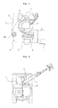
Figs. 1 and 2 , a hydraulic pipe fixing device for a boom-swing type excavator in the related art includes aboom supporter 4 mounted on a front end portion of anupper frame 1 to swing by anupper pin 2 and alower pin 3; aboom 6 and aboom cylinder 7 rotatably mounted on theboom supporter 4 byfixing pins upper frame 1 and the other end that is mounted on theboom supporter 4 to be driven to make theboom supporter 4 swing about theupper pin 2 and thelower pin 3 as center shafts;hydraulic hoses 9 for attachments supplying hydraulic fluid from a main control valve (not illustrated) MCV that is mounted on theupper frame 1 to an arm cylinder (not illustrated); andhydraulic hoses 10 for option devices supplying the hydraulic fluid to the option devices, such as quick fit, 2pcs boom, and hammer. - In this case, the
hydraulic hose 10 for option devices is arranged on a side surface of theboom supporter 4 in an exposed state, and thehydraulic hose 9 for attachments is arranged to pass through a space between theupper pin 2 and thelower pin 3. Due to this, in the case where various kinds of option devices, such as a hammer, required by equipment users are added, it is difficult to arrange and assemble the hydraulic hoses for supplying the hydraulic fluid to the option devices with respect to theboom supporter 4 to lower the workability. - Further, as shown in
FIG. 2 , in the case where theboom 6 swings at a maximum angle set in a left or right direction according to the driving of a boom swing cylinder 8, thehydraulic hoses boom 6. In this case, due to frequent frictional contact with surrounding components, thehydraulic hoses boom 6, external alignment states of thehydraulic hoses hydraulic hoses - Further, since it is difficult to align corresponding hydraulic hoses due to addition of various kinds of option devices required by the equipment users, the number of option devices that can be additionally mounted on the equipment may be limited. On the other hand, since the
hydraulic hoses hydraulic hoses - Therefore, the present invention has been made to solve the above-mentioned problems occurring in the related art, and one embodiment of the present invention is related to a hydraulic pipe fixing device for a boom-swing type excavator, which can maintain good external appearance states of hydraulic hoses according to additional option devices through arrangement of the hydraulic hoses for attachments and option devices at predetermined positions of a clamp mounted therein via a lower end portion of a boom supporter, and can prevent damage of the hydraulic hoses even in the case where the boom swings at the maximum angle through securing of a larger hose bending radius of the hydraulic hoses.
- One embodiment of the present invention is related to a hydraulic pipe fixing device for a boom-swing type excavator, which can arrange corresponding hydraulic hoses at predetermined positions of a boom supporter even in the case where various kinds of option devices are added, and thus can mount the option devices having the specification required by equipment users.
- One embodiment of the present invention is related to a hydraulic pipe fixing device for a boom-swing type excavator, which can improve workability in repair and assembling through pressing of hydraulic hoses by a cover for fixing the hydraulic hoses having two-stage fastening portion in the case where the hydraulic hoses are arranged at upper and lower predetermined positions of a clamp that is fixed in a boom supporter.
- In accordance with one aspect of the present invention, a hydraulic pipe fixing apparatus for a boom-swing type excavator, having an upper frame mounted on a lower traveling structure, a boom supporter mounted on a front end portion of the upper frame to swing and provided with a boom and a boom cylinder mounted thereon, and a boom swing cylinder making the boom supporter swing against the upper frame, the hydraulic pipe fixing apparatus includes a clamp on which seating grooves for seating hydraulic hoses for attachments and hydraulic hoses for option devices are formed so as to arrange the hydraulic hoses for the attachments including the boom and the hydraulic hoses for the additional option devices in predetermined positions inside the boom supporter; and a cover for fixing the hydraulic hoses that is detachably fixed to the clamp by a fastening member so as to prevent the hydraulic hoses from seceding from the seating grooves and to intercept mutual contact of a boom cylinder fixing member and the hydraulic hoses for the attachments and the option devices that move toward the boom cylinder side when hydraulic fluid is supplied to the hydraulic hoses for the attachments and the option devices.
- According to the aspect of the present invention, the cover for fixing the hydraulic hoses has assembling holes formed thereon and composed of a first through-hole into which a head portion of the fastening member is fitted and a second through-hole formed to communicate with the first through-hole with a size that is relatively smaller than the size of the first through-hole.
- The hydraulic pipe fixing apparatus according to the aspect of the present invention further includes a cover for protecting the hydraulic hoses that is detachably fixed to a bottom portion of the boom supporter by the fastening member to protect the hydraulic hoses for the attachments and the option devices that are exposed to the bottom of the boom supporter from external impact.
- According to the aspect of the present invention, the hydraulic hoses for the attachments and the hydraulic hoses for the option devices are arranged to be seated on the clamp of the boom supporter through through-holes formed on a lower end portion of a front surface of the upper frame and a guide portion formed on a bottom surface of the boom supporter so as to minimize bending of the hydraulic hoses for the attachments and the option devices when the boom swings at a maximum angle set in a left or right direction.
- According to the aspect of the present invention, in the case where the option devices are a quick fit, a drain, and a safety valve (ADV), the seating grooves in which the hydraulic hoses are seated are formed on an upper surface of the clamp.
- According to the aspect of the present invention, the cover for fixing the hydraulic hoses includes a first pressing portion fixed to the clamp by the fastening member to prevent the hydraulic hoses from seceding from the seating grooves of the clamp; and a second pressing portion formed to extend toward a lower side of the first pressing portion to intercept the contact of the hydraulic hoses and the boom cylinder fixing member through pressing of the hydraulic hoses positioned on a lower side of the clamp toward the boom supporter side.
- The hydraulic pipe fixing apparatus for a boom-swing type excavator as configured above according to the aspect of the present invention has the following advantages.
- Since the hydraulic hoses for attachments and option devices are arranged at predetermined positions of a clamp mounted therein via a lower end portion of a boom supporter, the hydraulic hoses according to additional option devices maintain good external appearance states. Also, even in the case where the boom swings at the maximum angle, the hose bending radius is slow, and thus the hydraulic hoses can be prevented from being damaged.
- Further, even in the case where various kinds of option devices are added, the corresponding hydraulic hoses can be arranged at predetermined positions of the boom supporter, and thus the option devices having the specification required by equipment users can be mounted to increase the work range using the excavator.
- Further, in the case where the hydraulic hoses are arranged at the upper and lower predetermined positions of the clamp that is fixed in the boom supporter, the cover for fixing the hoses having the two-stage fastening portion can be rapidly mounted to shorten the work time to repair and assemble the hydraulic hoses.
- The above objects, other features and advantages of the present invention will become more apparent by describing the preferred embodiments thereof with reference to the accompanying drawings, in which:
-
Fig. 1 is a view of a boom-swing type excavator for the extraction of a main portion in the related art; -
Fig. 2 is a plan view of a general boom-swing type excavator; -
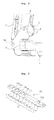
Fig. 3 is a side view of a hydraulic pipe fixing apparatus for a boom-swing type excavator for the extraction of a main portion according to an embodiment of the present invention; -
Fig. 4 is a perspective view of a clamp mounted in a boom supporter to arrange hydraulic hoses at predetermined positions in a hydraulic pipe fixing apparatus for a boom-swing type excavator according to an embodiment of the present invention; -
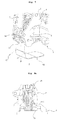
Fig. 5 is a perspective view of a cover for fixing hydraulic hoses to prevent the hydraulic hoses from seceding from a clamp in a hydraulic pipe fixing apparatus for a boom-swing type excavator according to an embodiment of the present invention; -
Fig. 6 is a perspective view of a cover for protecting hydraulic hoses that are exposed to a lower end portion of a boom supporter from external impact in a hydraulic pipe fixing apparatus for a boom-swing type excavator according to an embodiment of the present invention; -
Fig. 7 is a view of a cover for protecting hydraulic hoses in use state in a hydraulic pipe fixing apparatus for a boom-swing type excavator according to an embodiment of the present invention; -
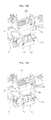
Figs. 8A to 8C are views illustrating bending of hydraulic hoses in a neutral state or in a swing state of a boom supporter in a hydraulic pipe fixing apparatus for a boom-swing type excavator according to an embodiment of the present invention; -
Fig. 9 is a view of hydraulic hoses that are arranged to be fixed to a boom by a clamp mounted on a boom supporter in a hydraulic pipe fixing apparatus for a boom-swing type excavator according to an embodiment of the present invention; -
Figs. 10A to 10C are views explaining a mount order of a cover for fixing hydraulic hoses in a hydraulic pipe fixing apparatus for a boom-swing type excavator according to an embodiment of the present invention; and -
Fig. 11 is a view explaining seating of hydraulic hoses on a clamp in a hydraulic pipe fixing apparatus for a boom-swing type excavator according to an embodiment of the present invention. -
- 1:
- upper frame
- 4:
- boom supporter
- 5, 21:
- fixing pin
- 6:
- boom
- 7:
- boom cylinder
- 8:
- boom swing cylinder
- 9:
- hydraulic hoses for attachments
- 10:
- hydraulic hoses for option devices
- 11:
- seating groove
- 12:
- clamp
- 13:
- boom cylinder fixing member
- 14, 17:
- fastening member
- 15:
- cover for fixing hydraulic hoses
- 16:
- assembling hole
- 18:
- cover for protecting hydraulic hoses
- 19:
- through-hole
- 20:
- guide portion
- Now, preferred embodiments of the present invention will be described in detail with reference to the accompanying drawings. The matters defined in the description, such as the detailed construction and elements, are nothing but specific details provided to assist those of ordinary skill in the art in a comprehensive understanding of the invention, and the present invention is not limited to the embodiments disclosed hereinafter.
- According to an embodiment of the present invention as illustrated in
Figs. 3 to 11 , a hydraulic pipe fixing apparatus for a boom-swing type excavator, having an upper frame 1 mounted on a lower traveling structure, a boom supporter 4 mounted on a front end portion of the upper frame 1 to swing about a fixing pin 21 as a center shaft and provided with a boom 6 and a boom cylinder 7 mounted thereon, and a boom swing cylinder 8 making the boom supporter 4 swing against the upper frame 1, the hydraulic pipe fixing apparatus includes a clamp 12 on which seating grooves 11 (11a to 11j) for seating hydraulic hoses (flexible hoses that can be bent) 9 for attachments and hydraulic hoses (flexible hoses that can be bent) 10 for option devices are formed so as to arrange the hydraulic hoses 9 for the attachments including the boom 6 and an arm and the hydraulic hoses 10 for the additional option devices, such as a rotator and a shear, in predetermined positions inside the boom supporter 4; and a cover 15 for fixing the hydraulic hoses that is detachably fixed to the clamp 12 by a fastening member 14 so as to prevent the hydraulic hoses 9 and 10 from seceding from the seating grooves 11 and to intercept mutual contact of a boom cylinder fixing member (a fixing pin and a boss for the boom cylinder) 13 and the hydraulic hoses 9 and 10 for the attachments and the option devices that move toward the side of the boom cylinder 7 when hydraulic fluid is supplied to the hydraulic hoses 9 and 10 for the attachments and the option devices. - In this case, the
cover 15 for fixing the hydraulic hoses has assemblingholes 16 formed thereon and composed of a first through-hole 16a into which a head portion (e.g., screw hex) of thefastening member 14 is fitted and a second through-hole 16b formed to communicate with the first through-hole 16a with a size that is relatively smaller than the size of the first through-hole 16a. - The hydraulic pipe fixing apparatus according to an embodiment of the present invention further includes a
cover 18 for protecting the hydraulic hoses that is detachably fixed to a bottom portion of theboom supporter 4 by afastening member 17 to protect thehydraulic hoses boom supporter 4 from external impact. - The
hydraulic hoses clamp 12 of theboom supporter 4 through through-holes 19 formed on a lower end portion of a front surface of theupper frame 1 and aguide portion 20 formed on a bottom surface of theboom supporter 4 so as to minimize bending of thehydraulic hoses boom 6 swings at a maximum angle set in a left or right direction. - In the case where the option devices are a quick fit, a drain, and a safety valve (ADV), the seating grooves 11 (11k to 11p) in which the hydraulic hoses 10a are seated are formed on an upper surface of the
clamp 12. - The
cover 15 for fixing the hydraulic hoses includes a firstpressing portion 15a fixed to theclamp 12 by thefastening member 14 to prevent thehydraulic hoses seating grooves 11 of theclamp 12; and a secondpressing portion 15b formed to extend toward a lower side of the firstpressing portion 15a to intercept the contact of thehydraulic hoses cylinder fixing member 13 through pressing of thehydraulic hoses clamp 12 toward the side of theboom supporter 4. - On the other hand, the configuration to make the
boom supporter 4 swing against theupper frame 1 according to the driving of the above-described boom swing cylinder 8 and to drive the attachments, such as the boom, and the option devices, such as shear, by the hydraulic fluid from a main control valve MCV mounted on theupper frame 1 is a well-known technology in the corresponding field of a boom-swing type excavator, and thus the detailed explanation of the configuration and operation thereof will be omitted. - Hereinafter, a use example of a hydraulic pipe fixing apparatus for a boom-swing type excavator according to an embodiment of the present invention will be described in detail with reference to the accompanying drawings.
- As shown in
Figs. 8A to 8C ,9 , and10A to 10C , thehydraulic hoses 9 for attachments and thehydraulic hoses 10 for option devices, which supply hydraulic fluid from the main control valve MCV (not illustrated) mounted on theupper frame 1 to the attachments, such as the arm cylinder, and the option devices, such as the rotator, are arranged at predetermined positions by theclamp 12 mounted inside theboom supporter 4. In this case, thehydraulic hoses 9 for the attachments and thehydraulic hoses 10 for the option devices are connected to metal hydraulic pipes 25 for the attachments and the option devices which are mounted on an outer surface of the structure of theboom 6. - As shown in
Fig. 9 , thehydraulic hoses 9 for the attachments and thehydraulic hoses 10 for the option devices having inlet sides connected to the main control valve are seated in theseating grooves 11 formed on theclamp 12 mounted in theboom supporter 4 through the throughhole 19 formed on the lower end portion of the front surface of theupper frame 1 and the guide portion (positioned on the lower side of the fixingpin 21 that fixes theboom supporter 4 to theupper frame 1 to swing) 20 formed on the bottom surface of theboom supporter 4 in order. - As shown in
Figs. 4 and11 , a 2pcs boom, a shear, an arm, a bucket, a bucket, an arm, a shear, a 2pcs boom, a rotator, and hydraulic hoses a to j that correspond to the rotator are arranged to be seated in theseating grooves 11a to 11j that are successively formed on the bottom surface of theclamp 12 mounted in theboom supporter 4. - As shown in
Fig. 11 , a drain, a quick fit, a quick fit, an anti-drop valve (ADV), and hydraulic hoses k to p that correspond to a lamp are arranged to be seated in the seating grooves 11k to 11p formed on the upper surface of theclamp 12. - As shown in
Figs. 5 and10A to 10C , thecover 15 for fixing the hydraulic hoses is detachably fixed to theclamp 12 by thefastening member 14. - As shown in
Figs. 5 and10B , the head portion (screw hex) of the fastening member 14 (at this time, thefastening member 14 is not completely fastened, but is temporarily assembled) which fixes theclamp 12 to theboom supporter 4 is fitted into the first through-hole 16a that forms the assemblinghole 16 formed on thecover 15 for fixing the hydraulic hoses. - As shown in
Figs. 5 and10C , if thecover 15 for fixing the hydraulic hoses is lowered toward the ground in a state where thecover 15 for fixing the hydraulic hoses comes in close contact with theclamp 12, thefastening member 14 is positioned in the second through-hole 16b that communicates with the first through-hole 16a. At this time, thefastening member 14 is completely tightened to be fixed. - The
hydraulic hoses boom cylinder 7 due to internal pressure that is formed when hydraulic fluid is supplied to thehydraulic hoses hydraulic hoses seating grooves 11 by the firstpressing portion 15a of thecover 15 for fixing the hydraulic hoses fixed to theclamp 12. Further, the contact between thehydraulic hoses boom cylinder 7, and the boom cylinder fixing member (fixing pin and a boss for boom cylinder) 13 can be intercepted by the second pressing portion of thecover 15 for fixing the hydraulic hoses. Through this, thehydraulic hoses hydraulic hoses boom supporter 4 can be protected from external impact by thecover 15 for fixing the hydraulic hoses. - As shown in
Figs. 6 and7 , thecover 18 for protecting the hydraulic hoses is fixed to theguide portion 20 that is formed on the bottom surface of theboom supporter 4 to pass thehydraulic hoses fastening member 17. Through this, thehydraulic hoses hole 19 formed on the front surface of theupper frame 1 and theguide portion 20 of theboom supporter 4, and thus thehydraulic hoses boom supporter 4 can be protected from the external impact. - As shown in
Fig. 11 , since thehydraulic hoses 9 for the attachments, such as the boom and the arm, and thehydraulic hoses 10 for the additional option devices are arranged in the predetermined positions in theboom supporter 4, the work time required to arrange the hydraulic hoses for the additional option devices can be shortened even if various kinds of option devices are added according to the equipment user's request. - As shown in
Fig. 8A , if the boom swing cylinder 8 is in an initial driving state and theboom 6 is positioned in the same direction as the forward and backward direction of the equipment, thehydraulic hoses hole 19 of theupper frame 1 and then enter into theboom supporter 4 along theguide portion 20 of theboom supporter 4 in a state where thehydraulic hoses - As shown in
Fig. 8B , due to the expansion driving of the boom swing cylinder 8, theboom 6 swings at the maximum angle in the right direction (based on the front surface of the equipment) of the equipment. At this time, thehydraulic hoses hole 19 of theupper frame 1 and then enter into theboom supporter 4 along theguide portion 20 of theboom supporter 4 in a state where thehydraulic hoses hydraulic hoses - As shown in
Fig. 8C , due to the contraction driving of the boom swing cylinder 8, theboom 6 swings at the maximum angle in the left direction (based on the front surface of the equipment) of the equipment. At this time, thehydraulic hoses hole 19 of theupper frame 1 and then enter into theboom supporter 4 along theguide portion 20 of theboom supporter 4 in a state where thehydraulic hoses hydraulic hoses - As shown in
Figs. 8A to 8C , thehydraulic hoses clamp 12 mounted in theboom supporter 4, and even if theboom 6 swings at the set maximum angle in the left or right direction through the driving of the boom swing cylinder 8, thehydraulic hoses hydraulic hoses - As apparent from the above description, according to the present invention having the above-described configuration, since the hydraulic hoses for the attachments and the option devices are arranged at the predetermined positions of the clamp mounted inside the boom supporter through the lower end portion of the boom supporter, the hydraulic hoses can be well arranged in accordance with the additional option devices. Further, even if the boom swings at the set maximum angle, the hydraulic hoses can move gently. Even if various kinds of option devices are added according to the equipment user's request, the corresponding hydraulic hoses can be arranged at the predetermined positions of the boom supporter.
Claims (6)
- A hydraulic pipe fixing apparatus for a boom-swing type excavator, having an upper frame mounted on a lower traveling structure, a boom supporter mounted on a front end portion of the upper frame to swing and provided with a boom and a boom cylinder mounted thereon, and a boom swing cylinder making the boom supporter swing against the upper frame, the hydraulic pipe fixing apparatus comprising:a clamp on which seating grooves for seating hydraulic hoses for attachments and hydraulic hoses for option devices are formed so as to arrange the hydraulic hoses for the attachments including the boom and the hydraulic hoses for the additional option devices in predetermined positions inside the boom supporter; anda cover for fixing the hydraulic hoses that is detachably fixed to the clamp by a fastening member so as to prevent the hydraulic hoses from seceding from the seating grooves and to intercept mutual contact of a boom cylinder fixing member and the hydraulic hoses for the attachments and the option devices that move toward the boom cylinder side when hydraulic fluid is supplied to the hydraulic hoses for the attachments and the option devices.
- The hydraulic pipe fixing apparatus according to claim 1, wherein the cover for fixing the hydraulic hoses has assembling holes formed thereon and composed of a first through-hole into which a head portion of the fastening member is fitted and a second through-hole formed to communicate with the first through-hole with a size that is relatively smaller than the size of the first through-hole.
- The hydraulic pipe fixing apparatus according to claim 1, further comprising a cover for protecting the hydraulic hoses that is detachably fixed to a bottom portion of the boom supporter by the fastening member to protect the hydraulic hoses for the attachments and the option devices that are exposed to the bottom of the boom supporter from external impact.
- The hydraulic pipe fixing apparatus according to claim 1, wherein the hydraulic hoses for the attachments and the hydraulic hoses for the option devices are arranged to be seated on the clamp of the boom supporter through through-holes formed on a lower end portion of a front surface of the upper frame and a guide portion formed on a bottom surface of the boom supporter so as to minimize bending of the hydraulic hoses for the attachments and the option devices when the boom swings at a maximum angle set in a left or right direction.
- The hydraulic pipe fixing apparatus according to claim 1, wherein in the case where the option devices are a quick fit, a drain, and a safety valve (ADV), the seating grooves in which the hydraulic hoses are seated are formed on an upper surface of the clamp.
- The hydraulic pipe fixing apparatus according to claim 1, wherein the cover for fixing the hydraulic hoses comprises:a first pressing portion fixed to the clamp by the fastening member to prevent the hydraulic hoses from seceding from the seating grooves of the clamp; anda second pressing portion formed to extend toward a lower side of the first pressing portion to intercept the contact of the hydraulic hoses and the boom cylinder fixing member through pressing of the hydraulic hoses positioned on a lower side of the clamp toward the boom supporter side.
Applications Claiming Priority (1)
| Application Number | Priority Date | Filing Date | Title |
|---|---|---|---|
| PCT/KR2011/009204 WO2013081212A1 (en) | 2011-11-30 | 2011-11-30 | Hydraulic line fixing apparatus for boom swing-type excavators |
Publications (2)
| Publication Number | Publication Date |
|---|---|
| EP2787128A1 true EP2787128A1 (en) | 2014-10-08 |
| EP2787128A4 EP2787128A4 (en) | 2016-02-24 |
Family
ID=48535647
Family Applications (1)
| Application Number | Title | Priority Date | Filing Date |
|---|---|---|---|
| EP11876817.5A Withdrawn EP2787128A4 (en) | 2011-11-30 | 2011-11-30 | Hydraulic line fixing apparatus for boom swing-type excavators |
Country Status (6)
| Country | Link |
|---|---|
| US (1) | US20140367529A1 (en) |
| EP (1) | EP2787128A4 (en) |
| JP (1) | JP5902313B2 (en) |
| KR (1) | KR20140106518A (en) |
| CN (1) | CN103958786A (en) |
| WO (1) | WO2013081212A1 (en) |
Cited By (2)
| Publication number | Priority date | Publication date | Assignee | Title |
|---|---|---|---|---|
| EP3452401A4 (en) * | 2016-05-03 | 2020-01-15 | Ponsse OYJ | ARRANGEMENT IN THE LIFTING APPARATUS OF A CONSTRUCTION MACHINE, APPARATUS FOR LIFTING A CONSTRUCTION MACHINE, AND CONSTRUCTION MACHINE |
| EP3530816A4 (en) * | 2017-03-01 | 2020-06-10 | Hitachi Construction Machinery Tierra Co., Ltd. | EXCAVATOR |
Families Citing this family (14)
| Publication number | Priority date | Publication date | Assignee | Title |
|---|---|---|---|---|
| KR101822931B1 (en) * | 2013-02-06 | 2018-01-29 | 볼보 컨스트럭션 이큅먼트 에이비 | Swing Control System For Construction Machines |
| JP6152004B2 (en) * | 2013-07-30 | 2017-06-21 | ヤンマー株式会社 | Piping structure of construction machinery |
| JP6567383B2 (en) * | 2015-09-30 | 2019-08-28 | 株式会社クボタ | Working machine |
| JP6682262B2 (en) * | 2015-12-24 | 2020-04-15 | 株式会社クボタ | Work machine |
| SE542480C2 (en) | 2017-09-08 | 2020-05-19 | Epiroc Rock Drills Ab | Mining or construction vehicle enclosing a conduit arrangement |
| SE541217C2 (en) | 2017-09-08 | 2019-05-07 | Epiroc Rock Drills Ab | Mining or construction vehicle |
| US10161542B1 (en) | 2017-11-10 | 2018-12-25 | Cnh Industrial America Llc | Mounting hard lines to a vehicle frame |
| JP7183116B2 (en) * | 2019-06-04 | 2022-12-05 | 株式会社クボタ | work machine |
| US11835163B2 (en) * | 2021-02-12 | 2023-12-05 | Belden Canada Ulc | Strain relief assembly |
| CN115321272B (en) * | 2022-03-24 | 2024-10-29 | 中钢集团西安重机有限公司 | Hose motion system and method based on hose separation frame |
| CN114719113B (en) * | 2022-04-08 | 2024-01-02 | 中国航发沈阳发动机研究所 | Follow-up pipeline structure of double-dimensional rotary compound motion equipment |
| KR102633161B1 (en) * | 2023-03-02 | 2024-02-02 | 한성산업(주) | Mobile vehicle for constructing precast concrete slab |
| JP2024142157A (en) * | 2023-03-29 | 2024-10-10 | ヤンマーホールディングス株式会社 | Construction Machinery |
| AU2023248133A1 (en) * | 2023-10-12 | 2025-05-01 | Caterpillar Global Mining Equipment Llc | Hose retention system |
Family Cites Families (45)
| Publication number | Priority date | Publication date | Assignee | Title |
|---|---|---|---|---|
| US3620268A (en) * | 1970-02-25 | 1971-11-16 | British Ropes Ltd | Boom loader |
| US3860175A (en) * | 1972-12-21 | 1975-01-14 | Forms Const | Mobile concrete distributing boom apparatus |
| US3999784A (en) * | 1975-09-18 | 1976-12-28 | Caterpillar Tractor Co. | Tube clamp mounting |
| US3981329A (en) * | 1975-10-20 | 1976-09-21 | Maurice Wohlwend | Swivel type fluid coupling |
| US4105046A (en) * | 1977-03-31 | 1978-08-08 | Sturgis Clifford M | Detachable fluid coupling |
| WO1982000843A1 (en) * | 1979-07-16 | 1982-03-18 | T Mueller | Guard structure for hydraulic conduits of a mobile apparatus |
| JPH0137633B2 (en) * | 1979-07-16 | 1989-08-08 | Caterpillar Mitsubishi Ltd | |
| US4700737A (en) * | 1986-08-29 | 1987-10-20 | The Specialty Mfg. Co. | Combination wall mount, caddy mount garden hose reel |
| DE69004287T2 (en) * | 1989-02-16 | 1994-02-24 | Kubota Kk | Hydraulic pipe arrangement for a backhoe. |
| JPH0476282U (en) * | 1990-11-16 | 1992-07-03 | ||
| JP2563771Y2 (en) * | 1992-04-02 | 1998-02-25 | 株式会社クボタ | Construction machine hose clamp structure |
| DE29512650U1 (en) * | 1994-08-06 | 1995-10-05 | Hewing GmbH, 48607 Ochtrup | Device for fastening a pipeline on a substrate, in particular a floor heating pipe on a thermal insulation board |
| CN2366646Y (en) * | 1998-10-13 | 2000-03-01 | 江阴市南方钢塑五金厂 | Frame for supporting parallel pipes |
| US6758024B1 (en) * | 1999-11-24 | 2004-07-06 | Liebherr-Hydraulikbagger Gmbh | Industrial shaft, particularly for packaging equipment |
| JP4576592B2 (en) * | 2000-08-31 | 2010-11-10 | ヤンマー建機株式会社 | Wiring and piping mounting structure for work equipment |
| US6684537B2 (en) * | 2001-05-28 | 2004-02-03 | Kubota Corporation | Excavator with a piping structure for absorbing variations in hose length |
| JP3822133B2 (en) * | 2002-05-09 | 2006-09-13 | 株式会社クボタ | Hydraulic piping structure of swing work machine |
| JP4005428B2 (en) * | 2002-07-03 | 2007-11-07 | 日立建機株式会社 | Swivel construction machine |
| KR200304958Y1 (en) * | 2002-11-07 | 2003-02-19 | 대모 엔지니어링 주식회사 | Pipe Arrangement Structure for An Attachment Of Excavator |
| US6883761B2 (en) * | 2003-02-13 | 2005-04-26 | General Electric Company | Support for tubular members |
| JP4188779B2 (en) * | 2003-08-08 | 2008-11-26 | 日立建機株式会社 | Swivel construction machine |
| JP2005060976A (en) * | 2003-08-08 | 2005-03-10 | Hitachi Constr Mach Co Ltd | Swivel construction machine |
| EP1707689B1 (en) * | 2003-12-18 | 2015-02-25 | Hitachi Construction Machinery Co., Ltd. | Swivel joint for construction machine |
| JP4260687B2 (en) * | 2004-05-31 | 2009-04-30 | 株式会社クボタ | Swivel work machine |
| US8523120B2 (en) * | 2004-06-14 | 2013-09-03 | Komatsu Ltd. | Component support device and construction machine with component attached via the same |
| DE102004037459A1 (en) * | 2004-08-02 | 2006-02-23 | Liebherr-Hydraulikbagger Gmbh | Hydraulic quick coupling |
| JP2007008364A (en) * | 2005-07-01 | 2007-01-18 | Sumitomo (Shi) Construction Machinery Manufacturing Co Ltd | Cover opening/closing mechanism of construction machinery |
| US20080110650A1 (en) * | 2006-10-27 | 2008-05-15 | Martin Kevin L | Machine, hydraulic system and method for providing hydraulic power |
| JP4705056B2 (en) * | 2007-02-16 | 2011-06-22 | 日立建機株式会社 | Construction machinery |
| JP4922210B2 (en) * | 2008-03-06 | 2012-04-25 | ヤンマー株式会社 | Hydraulic piping structure of excavator |
| PL2297020T3 (en) * | 2008-07-11 | 2013-02-28 | Palfinger Ag | Vehicle crane having hose guide |
| JP5124501B2 (en) * | 2009-02-05 | 2013-01-23 | 株式会社クボタ | Boom structure of swing work machine |
| CN201554949U (en) * | 2009-11-10 | 2010-08-18 | 周月明 | Combined pipe support |
| JP5602944B2 (en) * | 2010-05-17 | 2014-10-08 | ボルボ コンストラクション イクイップメント アーベー | Hydraulic piping fixing device for construction machinery |
| NL2004784C2 (en) * | 2010-05-31 | 2011-12-01 | Hudson Bay Holding B V | BELT WORK ARM WITH IMPROVED FITTING OF THE PIPES. |
| JP5177201B2 (en) * | 2010-10-20 | 2013-04-03 | コベルコ建機株式会社 | Piping clamp for construction machinery |
| JP5525488B2 (en) * | 2011-06-24 | 2014-06-18 | 日立建機株式会社 | Swivel construction machine |
| JP5891699B2 (en) * | 2011-10-13 | 2016-03-23 | コベルコ建機株式会社 | Work machine |
| CN103890278A (en) * | 2011-10-17 | 2014-06-25 | 沃尔沃建造设备有限公司 | Device for fixing the hydraulic piping of construction equipment |
| JP5510488B2 (en) * | 2012-03-29 | 2014-06-04 | コベルコ建機株式会社 | Work machine |
| ZA201302779B (en) * | 2012-04-20 | 2013-11-27 | Harnischfeger Tech Inc | Fluid conveyance system for earthmoving machine |
| JP5290453B1 (en) * | 2012-05-22 | 2013-09-18 | 株式会社小松製作所 | Excavator |
| US8951001B2 (en) * | 2012-09-17 | 2015-02-10 | Caterpillar Global Mining Llc | Hose arrangement for stick and bucket of machine |
| AU2013245549B2 (en) * | 2012-10-19 | 2017-05-25 | Joy Global Surface Mining Inc | Conduit support system |
| IN2014DN07851A (en) * | 2013-02-11 | 2015-04-24 | Harnischfeger Tech Inc |
-
2011
- 2011-11-30 WO PCT/KR2011/009204 patent/WO2013081212A1/en not_active Ceased
- 2011-11-30 EP EP11876817.5A patent/EP2787128A4/en not_active Withdrawn
- 2011-11-30 JP JP2014544633A patent/JP5902313B2/en not_active Expired - Fee Related
- 2011-11-30 CN CN201180075101.XA patent/CN103958786A/en active Pending
- 2011-11-30 US US14/361,001 patent/US20140367529A1/en not_active Abandoned
- 2011-11-30 KR KR1020147013905A patent/KR20140106518A/en not_active Ceased
Cited By (3)
| Publication number | Priority date | Publication date | Assignee | Title |
|---|---|---|---|---|
| EP3452401A4 (en) * | 2016-05-03 | 2020-01-15 | Ponsse OYJ | ARRANGEMENT IN THE LIFTING APPARATUS OF A CONSTRUCTION MACHINE, APPARATUS FOR LIFTING A CONSTRUCTION MACHINE, AND CONSTRUCTION MACHINE |
| US11028552B2 (en) | 2016-05-03 | 2021-06-08 | Ponsse Oyj | Arrangement in the hoisting apparatus of a work machine, hoisting apparatus of a work machine, and work machine |
| EP3530816A4 (en) * | 2017-03-01 | 2020-06-10 | Hitachi Construction Machinery Tierra Co., Ltd. | EXCAVATOR |
Also Published As
| Publication number | Publication date |
|---|---|
| US20140367529A1 (en) | 2014-12-18 |
| KR20140106518A (en) | 2014-09-03 |
| JP5902313B2 (en) | 2016-04-13 |
| EP2787128A4 (en) | 2016-02-24 |
| WO2013081212A1 (en) | 2013-06-06 |
| CN103958786A (en) | 2014-07-30 |
| JP2015500407A (en) | 2015-01-05 |
Similar Documents
| Publication | Publication Date | Title |
|---|---|---|
| US20140367529A1 (en) | Hydraulic line fixing apparatus for boom swing-type excavators | |
| JP4713516B2 (en) | Construction machinery | |
| CN101768987B (en) | Hydraulic crusher | |
| EP2960378B1 (en) | Pipe supporting device for construction machine | |
| KR20110116866A (en) | Excavator's tongs | |
| EP2098644A2 (en) | Apparatus for fixing hydraulic pipes for construction equipment | |
| JP2020051047A (en) | Construction machine | |
| DE502004001501D1 (en) | STORAGE BETWEEN COMPONENTS ON CONSTRUCTION MACHINES | |
| US20130256468A1 (en) | Device for fixing hydraulic pipe of boom swing type excavator | |
| US20040187366A1 (en) | Piping arrangement for swing type hydraulic excavators | |
| US20090084454A1 (en) | Apparatus for fixing hydraulic pipes for zero tail swing excavator | |
| KR200492231Y1 (en) | Tong attachment for excavator | |
| JP5789158B2 (en) | Cylinder equipment for construction machinery | |
| JP2004108055A (en) | Working device of construction machine | |
| KR101820033B1 (en) | A boom for tractor loader | |
| US12180684B2 (en) | Pipe protection unit in work machine | |
| CA2820565C (en) | Hydraulic assembly and logging equipment using same | |
| JP7572283B2 (en) | Multi-boom work machine | |
| JP2013053453A (en) | Joint of hydraulic hose | |
| KR20250050797A (en) | Hammer with an auxiliary boom equipped with a swivel unit | |
| JP2001032316A (en) | Attachment piping structure for hydraulic backhoe | |
| JPH11336112A (en) | Construction machine | |
| JP2024103998A (en) | Work Machine | |
| KR20220012711A (en) | Displacement adjusting device for exhaust pipe unit for construction machinery | |
| JP2021179109A (en) | Working machine equipped with a detachable mechanism and a detachable mechanism |
Legal Events
| Date | Code | Title | Description |
|---|---|---|---|
| PUAI | Public reference made under article 153(3) epc to a published international application that has entered the european phase |
Free format text: ORIGINAL CODE: 0009012 |
|
| 17P | Request for examination filed |
Effective date: 20140522 |
|
| AK | Designated contracting states |
Kind code of ref document: A1 Designated state(s): AL AT BE BG CH CY CZ DE DK EE ES FI FR GB GR HR HU IE IS IT LI LT LU LV MC MK MT NL NO PL PT RO RS SE SI SK SM TR |
|
| DAX | Request for extension of the european patent (deleted) | ||
| RIC1 | Information provided on ipc code assigned before grant |
Ipc: E02F 9/08 20060101ALN20150803BHEP Ipc: F16L 3/22 20060101ALI20150803BHEP Ipc: E02F 3/38 20060101ALI20150803BHEP Ipc: F16L 3/223 20060101ALI20150803BHEP Ipc: E02F 9/14 20060101AFI20150803BHEP Ipc: F16L 3/01 20060101ALI20150803BHEP Ipc: E02F 9/22 20060101ALI20150803BHEP |
|
| RA4 | Supplementary search report drawn up and despatched (corrected) |
Effective date: 20160125 |
|
| RIC1 | Information provided on ipc code assigned before grant |
Ipc: E02F 9/22 20060101ALI20160119BHEP Ipc: E02F 9/14 20060101AFI20160119BHEP Ipc: E02F 3/38 20060101ALI20160119BHEP Ipc: F16L 3/22 20060101ALI20160119BHEP Ipc: F16L 3/01 20060101ALI20160119BHEP Ipc: F16L 3/223 20060101ALI20160119BHEP Ipc: E02F 9/08 20060101ALN20160119BHEP |
|
| STAA | Information on the status of an ep patent application or granted ep patent |
Free format text: STATUS: THE APPLICATION IS DEEMED TO BE WITHDRAWN |
|
| 18D | Application deemed to be withdrawn |
Effective date: 20160823 |