EP2786821A1 - Outil de coupe à arête de lame interchangeable et plaquette de coupe - Google Patents
Outil de coupe à arête de lame interchangeable et plaquette de coupe Download PDFInfo
- Publication number
- EP2786821A1 EP2786821A1 EP12852492.3A EP12852492A EP2786821A1 EP 2786821 A1 EP2786821 A1 EP 2786821A1 EP 12852492 A EP12852492 A EP 12852492A EP 2786821 A1 EP2786821 A1 EP 2786821A1
- Authority
- EP
- European Patent Office
- Prior art keywords
- lever
- cutting insert
- insert
- cutting
- side wall
- Prior art date
- Legal status (The legal status is an assumption and is not a legal conclusion. Google has not performed a legal analysis and makes no representation as to the accuracy of the status listed.)
- Granted
Links
- 238000003825 pressing Methods 0.000 claims abstract description 48
- 230000001154 acute effect Effects 0.000 claims description 20
- 230000007423 decrease Effects 0.000 claims 1
- 238000003780 insertion Methods 0.000 description 6
- 230000037431 insertion Effects 0.000 description 6
- 230000000694 effects Effects 0.000 description 3
- 238000003754 machining Methods 0.000 description 3
- 230000007246 mechanism Effects 0.000 description 3
- 230000009471 action Effects 0.000 description 2
- 238000006073 displacement reaction Methods 0.000 description 2
- 230000000149 penetrating effect Effects 0.000 description 2
- 230000000903 blocking effect Effects 0.000 description 1
- 238000004891 communication Methods 0.000 description 1
- 230000005489 elastic deformation Effects 0.000 description 1
- 230000005484 gravity Effects 0.000 description 1
- 238000000034 method Methods 0.000 description 1
- 238000003801 milling Methods 0.000 description 1
- 230000008569 process Effects 0.000 description 1
Images


Classifications
-
- B—PERFORMING OPERATIONS; TRANSPORTING
- B23—MACHINE TOOLS; METAL-WORKING NOT OTHERWISE PROVIDED FOR
- B23C—MILLING
- B23C5/00—Milling-cutters
- B23C5/02—Milling-cutters characterised by the shape of the cutter
- B23C5/06—Face-milling cutters, i.e. having only or primarily a substantially flat cutting surface
-
- B—PERFORMING OPERATIONS; TRANSPORTING
- B23—MACHINE TOOLS; METAL-WORKING NOT OTHERWISE PROVIDED FOR
- B23B—TURNING; BORING
- B23B27/00—Tools for turning or boring machines; Tools of a similar kind in general; Accessories therefor
- B23B27/14—Cutting tools of which the bits or tips or cutting inserts are of special material
- B23B27/16—Cutting tools of which the bits or tips or cutting inserts are of special material with exchangeable cutting bits or cutting inserts, e.g. able to be clamped
- B23B27/1614—Cutting tools of which the bits or tips or cutting inserts are of special material with exchangeable cutting bits or cutting inserts, e.g. able to be clamped with plate-like cutting inserts of special shape clamped against the walls of the recess in the shank by a clamping member acting upon the wall of a hole in the insert
- B23B27/1622—Cutting tools of which the bits or tips or cutting inserts are of special material with exchangeable cutting bits or cutting inserts, e.g. able to be clamped with plate-like cutting inserts of special shape clamped against the walls of the recess in the shank by a clamping member acting upon the wall of a hole in the insert characterised by having a special shape
-
- B—PERFORMING OPERATIONS; TRANSPORTING
- B23—MACHINE TOOLS; METAL-WORKING NOT OTHERWISE PROVIDED FOR
- B23B—TURNING; BORING
- B23B27/00—Tools for turning or boring machines; Tools of a similar kind in general; Accessories therefor
- B23B27/14—Cutting tools of which the bits or tips or cutting inserts are of special material
- B23B27/16—Cutting tools of which the bits or tips or cutting inserts are of special material with exchangeable cutting bits or cutting inserts, e.g. able to be clamped
-
- B—PERFORMING OPERATIONS; TRANSPORTING
- B23—MACHINE TOOLS; METAL-WORKING NOT OTHERWISE PROVIDED FOR
- B23C—MILLING
- B23C5/00—Milling-cutters
- B23C5/16—Milling-cutters characterised by physical features other than shape
- B23C5/20—Milling-cutters characterised by physical features other than shape with removable cutter bits or teeth or cutting inserts
- B23C5/22—Securing arrangements for bits or teeth or cutting inserts
- B23C5/2204—Securing arrangements for bits or teeth or cutting inserts with cutting inserts clamped against the walls of the recess in the cutter body by a clamping member acting upon the wall of a hole in the insert
- B23C5/2226—Securing arrangements for bits or teeth or cutting inserts with cutting inserts clamped against the walls of the recess in the cutter body by a clamping member acting upon the wall of a hole in the insert for plate-like cutting inserts fitted on an intermediate carrier, e.g. shank fixed in the cutter body
-
- B—PERFORMING OPERATIONS; TRANSPORTING
- B23—MACHINE TOOLS; METAL-WORKING NOT OTHERWISE PROVIDED FOR
- B23B—TURNING; BORING
- B23B2200/00—Details of cutting inserts
- B23B2200/04—Overall shape
- B23B2200/0423—Irregular
-
- B—PERFORMING OPERATIONS; TRANSPORTING
- B23—MACHINE TOOLS; METAL-WORKING NOT OTHERWISE PROVIDED FOR
- B23B—TURNING; BORING
- B23B2200/00—Details of cutting inserts
- B23B2200/04—Overall shape
- B23B2200/0457—Pentagonal
-
- B—PERFORMING OPERATIONS; TRANSPORTING
- B23—MACHINE TOOLS; METAL-WORKING NOT OTHERWISE PROVIDED FOR
- B23B—TURNING; BORING
- B23B2200/00—Details of cutting inserts
- B23B2200/12—Side or flank surfaces
- B23B2200/125—Side or flank surfaces discontinuous
-
- B—PERFORMING OPERATIONS; TRANSPORTING
- B23—MACHINE TOOLS; METAL-WORKING NOT OTHERWISE PROVIDED FOR
- B23B—TURNING; BORING
- B23B2200/00—Details of cutting inserts
- B23B2200/36—Other features of cutting inserts not covered by B23B2200/04 - B23B2200/32
- B23B2200/3618—Fixation holes
-
- B—PERFORMING OPERATIONS; TRANSPORTING
- B23—MACHINE TOOLS; METAL-WORKING NOT OTHERWISE PROVIDED FOR
- B23B—TURNING; BORING
- B23B2205/00—Fixation of cutting inserts in holders
- B23B2205/12—Seats for cutting inserts
-
- B—PERFORMING OPERATIONS; TRANSPORTING
- B23—MACHINE TOOLS; METAL-WORKING NOT OTHERWISE PROVIDED FOR
- B23C—MILLING
- B23C2210/00—Details of milling cutters
- B23C2210/16—Fixation of inserts or cutting bits in the tool
- B23C2210/163—Indexing
-
- B—PERFORMING OPERATIONS; TRANSPORTING
- B23—MACHINE TOOLS; METAL-WORKING NOT OTHERWISE PROVIDED FOR
- B23C—MILLING
- B23C2210/00—Details of milling cutters
- B23C2210/50—Cutting inserts
- B23C2210/503—Cutting inserts mounted internally on the cutter
-
- Y—GENERAL TAGGING OF NEW TECHNOLOGICAL DEVELOPMENTS; GENERAL TAGGING OF CROSS-SECTIONAL TECHNOLOGIES SPANNING OVER SEVERAL SECTIONS OF THE IPC; TECHNICAL SUBJECTS COVERED BY FORMER USPC CROSS-REFERENCE ART COLLECTIONS [XRACs] AND DIGESTS
- Y10—TECHNICAL SUBJECTS COVERED BY FORMER USPC
- Y10T—TECHNICAL SUBJECTS COVERED BY FORMER US CLASSIFICATION
- Y10T407/00—Cutters, for shaping
- Y10T407/22—Cutters, for shaping including holder having seat for inserted tool
-
- Y—GENERAL TAGGING OF NEW TECHNOLOGICAL DEVELOPMENTS; GENERAL TAGGING OF CROSS-SECTIONAL TECHNOLOGIES SPANNING OVER SEVERAL SECTIONS OF THE IPC; TECHNICAL SUBJECTS COVERED BY FORMER USPC CROSS-REFERENCE ART COLLECTIONS [XRACs] AND DIGESTS
- Y10—TECHNICAL SUBJECTS COVERED BY FORMER USPC
- Y10T—TECHNICAL SUBJECTS COVERED BY FORMER US CLASSIFICATION
- Y10T407/00—Cutters, for shaping
- Y10T407/23—Cutters, for shaping including tool having plural alternatively usable cutting edges
Definitions
- the present invention relates to a cutting tool having a replaceable cutting edge portion i.e., an indexable cutting tool, and a cutting insert which serves as a replaceable cutting edge portion used for the cutting tool, and more particularly to an indexable cutting tool and a cutting insert in which improvements have been made in the shape of a through hole formed through the cutting insert and a clamping mechanism for fixing the cutting insert to a body of the cutting tool.
- indexable cutting tools use different systems for fixing or clamping a cutting insert depending on uses.
- a clamping system using an L-shaped lever placed inside a body is used since priority is given to easy replacement of cutting inserts (see, for example, PTL 1).
- This type of lever generally has a rod-shaped lever body, a clamp portion protruding laterally from one end of the lever body for pressing a cutting insert, and a protrusion provided in the middle of the lever body and protruding outwardly in a radial direction.
- the lever body is accommodated in a hole penetrating a body such that the clamp portion of the lever is positioned in a through hole formed on the cutting insert.
- a force is applied to the other end of the lever body so that the lever is inclined, with the protrusion serving as a fulcrum, and the cutting insert is pressed against a side wall of an insert fixing portion (tip seat) of the body, with the clamp portion of the lever serving as a point of action, thereby fixing the cutting insert.
- a clamping system using a screw is used to obtain a greater clamping force.
- the problem is particularly prominent in clamping the cutting insert having an acute corner (a corner with an acute angle defined by side surfaces which extend from the ends of the corner), such as a V-shaped cutting insert of the ISO standard, since the distance between a position where the clamp portion abuts on the cutting insert and a position where the cutting insert is pressed against side walls of an insert seat of the body is long.
- an acute corner a corner with an acute angle defined by side surfaces which extend from the ends of the corner
- Another problem of the conventional cutting insert is that shared use of the cutting insert for a cutting tool adopting the clamping system using a lever and for a cutting tool adopting the clamping system using a screw is not taken into consideration. More specifically, the cutting insert conventionally used for the cutting tool adopting the clamping system using a lever cannot be used for the cutting tool adopting the clamping system using a screw. Therefore, two types of cutting inserts having the same size need to be prepared for light cutting processing and heavy cutting processing. This occasionally causes a problem of an increase in management costs.
- the present invention has been made to solve the above problems.
- a cutting insert used for an indexable cutting tool comprising:
- an indexable cutting tool (A) using a cutting insert (2) in a replaceable manner comprising:
- the cutting insert (2) of the first aspect of the present invention since the cutting insert is adaptable to both a cutting tool with the clamping system using a lever and a cutting tool with the clamping system using a screw, management costs can be reduced.
- the indexable cutting tool (A) using the cutting insert (2) has the pressing member (4), wherein the position where a pressing force of the pressing member (4) is applied and the position of the fulcrum are defined such that the lever (3) is inclined around the fulcrum on the lever (3) in a manner that the one end (31) which applies a clamping force moves forward in a pressing direction. Accordingly, the pressing force can be applied to the lever (3) at a point close to the one end (31), and the pressing force applied to the lever (3) can be efficiently transmitted to the cutting insert (2) as compared to the conventional structure, thereby increasing a clamping force by the lever (3).
- Fig. 1 and Fig. 2 show an indexable cutting tool of the present embodiment.
- the indexable cutting tool A of the present invention has a body 1, a lever 3 for clamping a cutting insert 2, a screw 4 that is a pressing member for pressing the lever 3 to be inclined, and a spring 5.
- the left-side portion shows the leading end of the indexable cutting tool A
- the right-side portion shows the rear end of the indexable cutting tool A.
- a tip of the body 1 is partly cut out in a shape similar to the shape of the cutting insert 2 so that an insert fixing portion 11 is formed on which the cutting insert 2 is placed.
- Fig. 1 shows an insert fixing portion 11 on which the cutting insert 2 is placed.
- a space B in which the lever 3, the screw 4, and the spring 5 are arranged.
- the spring 5 and the lever 3 are arranged in the order from the rear end of the body 1 (right side of Fig. 2 ), and further the screw 4 is arranged so as to penetrate the spring 5 and the lever 3.
- a space C in which the lever 3 is arranged is formed vertically across the space B in the middle of the space B.
- the size of the space C is larger than the size of the lever 3. This allows the lever 3 to be inclined in the space C when a head of the screw 4 presses the lever 3 as shown in Fig. 2 .
- the space C is in communication with the insert fixing portion 11.
- a top end portion of the lever 3 arranged in the space C protrudes from a placement surface 12 (see Fig. 9 ) of the insert fixing portion 11.
- the spring 5 biases to the lever 3 toward the tip of the body 1, and has the function of returning the position of the inclined lever 3 to an initial state (described later) when the engagement of the head of the screw 4 with the lever 3 is released.
- the cutting insert of the present embodiment is substantially pentagonal in shape and has a pair of side surfaces that are adjacent to each other at an acute angle, a pair of opposite side surfaces that are opposite to each other in parallel and extend from the pair of side surfaces at obtuse angles in respective opposite sides of the acute portion, and a side surface formed to be square to the opposite side surfaces.
- the cutting insert 2 of the present embodiment is substantially a pentagon that is similar to the shape of a home plate in baseball. As shown in Fig. 1 , Fig. 3A , Fig. 3B , and Fig.
- two ridge portions 27 of the cutting insert 2 located at the rear end of the indexable cutting tool A define an acute angle and are smoothly connected to each other via a curved portion 21 (hereinafter referred to as "an acute corner portion").
- a cutting edge 24 is formed on an intersecting ridge portion between a top surface 22 of the cutting insert 2 and the side surface 23 to be positioned at the leading end of the indexable cutting tool A.
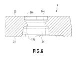
- the cutting insert 2 has a through hole 26 that penetrates from the top surface 22 to a bottom surface 25.
- the through hole 26 allows a screw to be inserted into a screw receiving portion formed on the placement surface 12.
- the through hole 26 of the present embodiment has a minor diameter portion 26a which is a first portion formed adjacent to the top surface 22, a major diameter portion 26b which is a second portion formed adjacent to the bottom surface 25, and a constricted portion 26c which is a space connecting the space defining the minor diameter portion 26a to the space defining the major diameter portion 26b.
- the diameter of the major diameter portion 26b is larger than the diameter of the minor diameter portion 26a. Accordingly, the major diameter portion 26b defines a space that is larger than the space defined by the minor diameter portion 26a, and in the through hole 26, an inner wall defining the major diameter portion 26b is located farthest from the central axis of the through hole 26.
- the major diameter portion 26b is a portion in which a top end portion of the lever 3 is accommodated when the cutting insert 2 is placed on the insert fixing portion 11, and the cutting insert 2 is fixed when the top end portion of the lever 3 presses the inner wall of the major diameter portion 26b.
- the minor diameter portion 26a is a portion in which a screw head is accommodated when the cutting insert 2 is used for a cutting tool with a clamping system using a screw.
- the constricted portion 26c is a portion which abuts on the screw head inserted into the through hole 26 when the cutting insert 2 is used for a cutting tool with a clamping system using a screw, so that the cutting insert 2 is pressed against the placement surface 12 of the insert fixing portion.
- the lever 3 is a rod-shaped member being substantially square pillar, and generally has a top end portion 31 protruding from the placement surface 12, a body portion 32 formed under the top end portion 31, and a bottom end portion 33 formed under the body portion 32.
- a back surface 32a of the body portion 32 facing the leading end of the body 1 includes a back lower portion 32a1 that is inclined from a portion connected to the bottom surface toward the left side of Fig. 8A and a back upper portion 32a2 that is connected to the back lower portion 32a1 and is inclined from the connecting portion 32a3 toward the right side of Fig. 8A with respect to the bottom surface of the bottom end portion 33 in terms of an angle. More specifically, an angle ⁇ defined by the back lower portion 32a1 and the bottom surface of the bottom end portion 33 is obtuse. Since the angle ⁇ is obtuse, the center of gravity of the lever 3 becomes closer to the back surface 32a, and the lever 3 can easily return to an initial non-inclined state when the screw 4 is loosened.
- the connecting portion 32a3 between the back lower portion 32a1 and the back upper portion 32a2 is located closest to the leading end when the lever 3 is arranged in the body 1.
- the screw 4 presses the connecting portion 32a3 so that the lever 3 is inclined from the initial state.
- a front surface 32b of the body portion 32 facing the rear end of the body 1, or located opposite to the back surface 32a includes a front lower portion that is inclined from a portion 32b3 connected to the bottom surface toward the right side of Fig. 8A and a front upper portion 32b2 that is connected to the front lower portion 32b1 and is inclined from the connecting portion 32b3 toward the left side of Fig. 8A with respect to the bottom surface of the bottom end portion 33 in terms of an angle. More specifically, an angle ⁇ defined by the front lower portion 32b1 and the front upper portion 32b2 is obtuse.
- the angle ⁇ between the front lower portion 32b1 and the front upper portion 32b2 is obtuse and the connecting portion 32b3 therebetween is located closer to the rear end of the body 1 than a portion of the top end portion 31 of the lever 3 which abuts on the inner wall of the major diameter portion 26b of the through hole 26, the fulcrum becomes closer to the rear end of the body 1 than the point of action, and when force is applied to the lever 3 to be inclined as screwing the screw 4 (described later), the top end portion 31 of the lever 3 applies a lateral downward force to the cutting insert 2. Accordingly, the cutting insert 2 receives not only force pressing the side wall but also force pressing the placement surface 12.
- a connecting portion 34 between the body portion 32 and the bottom end portion 33 is recessed, which allows the lever 3, when inclined, to avoid being in contact with a step portion 6 (described later).
- a portion of the bottom end portion 33 is cut out, and thus the bottom end portion 33 is smaller than the body portion 32.
- a cutting-out portion 33a is formed on the right side of the bottom end portion 33 in Fig. 7B and Fig. 8B (left side in Fig. 7A ).
- the cutting-out portion 33a engages the step portion 6 formed at a bottom of the space C formed in the body as shown in Fig. 9 and Fig. 10 .
- the step portion 6 is not formed all around the periphery of the bottom of the space C, but is formed partly.
- the bottom surface of the space C is directly connected to the side wall. This shape allows the bottom end portion 33 and the step portion 6 to be in contact with each other, and the lever 3 is not accommodated in the space C accordingly unless the front surface 32b of the lever 3 faces the rear end of the body 1. Accordingly, it is possible to prevent the lever 3 from being arranged in the space C in a state in which the front surface 32b of the body portion 32 is not facing the leading end of the body 1.
- the screw insertion hole 35 penetrating from the front surface 32b to the back surface 32a of the body portion 32.
- the screw 4 is inserted into the screw insertion hole 35.
- the screw insertion hole 35 has a width corresponding to the outside diameter of the screw 4 in a lateral direction, and is oval in shape with a height that is longer than the width in a longitudinal direction. This shape suppresses lateral movement of the screw 4 and allows the screw 4 to move back-and-forth smoothly.
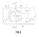
- Fig. 9 is an enlarged view of the insert fixing portion.
- a pair of side walls 11a is formed so as to sandwich the ridge portions 27 connected to the acute corner portion 21 when the cutting insert 2 is placed.
- an angle defined by the side walls of the insert fixing portion is not constant as shown in Fig. 9 , but becomes gradually smaller from the leading end portion of the body 1. More specifically, as shown in Fig.
- an angle defined by a pair of third side wall areas 300 located closest to the leading end portion is denoted by ⁇ 3
- an angle defined by a pair of second side wall areas 200 that is connected to the pair of third side wall areas 300 is denoted by ⁇ 2
- an angle defined by a pair of first side wall areas 100 that is connected to the pair of second side wall areas 200 is denoted by ⁇ 1.
- the angles satisfy the following relation: ⁇ 3> ⁇ 2> ⁇ 1.
- the angle ⁇ 1 and the angle ⁇ 2 are smaller than the angle at the acute corner portion 21 of the cutting insert 2, whereas the angle ⁇ 3 is larger than the angle at the acute corner portion 21 of the cutting insert 2.
- ⁇ 1 ⁇ -1.5°
- ⁇ 2 ⁇ -0.5°
- ⁇ 3 ⁇ +0.5°.
- Each of the side surfaces connected to the ridge portions 27 of the cutting insert 2 abuts on a point of a connecting portion 250 between the second side wall area 200 and the third side wall area 300.
- the head of the screw 4 applies force to the body portion 32 of the lever 3.
- the lever 3 which has received the pressing force from the screw 4 is inclined about a fulcrum, that is, the connecting portion 32b3 of the front surface 32b of the lever body portion that abuts on the inner wall of the body 1 facing the space C, and the top end portion 31 tends to move toward the rear end portion of the body 1, that is, forward in a pressing direction by the head of the screw 4. Accordingly, the top end portion 31 applies force to the inner wall defining the major diameter portion 26b of the through hole 26 so as to press the cutting insert 2 against the side wall 11a of the insert fixing portion 11.
- An advantageous effect of the present embodiment is that the force pressing the lever 3 is efficiently transmitted to the cutting insert 2, and a greater clamping force is obtained as compared to the conventional clamping system using a lever.
- the distance between a point where the head of the spring 4 applies force to the lever 3 to be inclined (point of effort) and a fulcrum, that is, the connecting portion 32b3 between the front upper portion and the front lower portion is very small as compared to the case of using the conventional L-shaped lever.
- the indexable cutting tool A of the present embodiment functions effectively when clamping the cutting insert having a long length from the center of the through hole to the corner, such as a V-shaped cutting insert.
- the shape of the side wall 11a of the insert fixing portion 11 contributes to the enhancement of the clamping force.
- an angle defined by side walls is constant, and the side walls are formed such that the angle defined by the side walls is larger than the angle at the acute corner of the cutting insert 2.
- the indexable cutting tool (A) of the present embodiment is configured such that the angle defined by the pair of side walls 11a gradually changes as shown in Fig. 11 , so that a point where the cutting insert 2 is in contact with or separates from the side walls 11a is shifted toward the rear end of the body 1.
- a cutting resistance (particularly thrust force) repeatedly applied to the cutting insert causes an angle (angle of divergence) between the side walls to increase gradually, and the side walls are occasionally separated from the cutting insert. This increases backlash of the cutting insert, and stable processing becomes impossible. At worst, the cutting insert or body may be damaged.
- the side surface connected to the ridge portion 27 of the cutting insert 2 abuts on the connecting portion 250 between the third side wall areas 300 which define the angle of divergence that is larger than the angle at the acute corner and the second side wall areas 200 which define the angle of divergence that is smaller than the angle at the acute corner.
- the cutting resistance applied to the cutting insert 2 causes elastic deformation of the second side wall areas 200 starting from the connecting portion 250
- the cutting insert 2 and the side wall 11a are kept in contact with each other since the second side wall areas 200 have the angle of divergence that is smaller than the angle at the acute corner.
- the side surfaces connected to the ridge portions 27 of the cutting insert 2 abut on connecting portions 150 (see Fig. 11 ) between the second side wall areas 200 and the first side wall areas 100.
- This allows clamp performance to be maintained for a longer period of time than that of a conventional example.
- the side wall structure of the present embodiment functions effectively particularly when the angle ⁇ 1 is acute, particularly, 60° or smaller.
- the cutting insert 2 of the present embodiment is adaptable not only to the cutting tool adopting a clamping system using a lever as described above, but also to a cutting tool adopting a clamping system using a screw.
- Fig. 12 is a cross-sectional view of the cutting insert 2 of the present embodiment that is clamped to a body 1' by using a screw 10.
- a screw receiving portion C' is formed, as shown in Fig. 12 , so that the screw 10 is screwed diagonally into the body 1' through a through hole of the cutting insert 2.
- the through hole 26 of the cutting insert 2 of the present embodiment has the major diameter portion 26b at a lower portion, and this makes it possible to adjust the inclination angle of the screw and the position of the tip of the screw and prevent the inner wall of the through hole 26 from blocking the proceeding of the screw 10. Accordingly, the head of the screw 10 accommodated in the minor diameter portion 26a presses the constricted portion 26c so as to clamp the cutting insert 2.
- the cutting insert 2 of the present embodiment is adaptable to both the clamping system using a screw and the clamping system using a lever.
- the lever 3, and others allows the cutting insert 2 to be clamped more firmly as compared to the conventional example. This is effective when clamping a cutting insert having a structure with an acute corner having a long distance between the center of a through hole and the corner.
- the present invention is also applicable to the case of clamping a cutting insert having other structures.
- the indexable cutting tool of the present invention is not limited to the above-described embodiment.
- the indexable cutting tool of the present invention is also applicable to general turning tools such as a turning tool for outside diameter machining and a turning tool for inside diameter machining, or milling tools.
- the shape of the minor diameter portion 26a which is a first portion of the through hole of the cutting insert and the shape of the major diameter portion 26b which is a second portion of the through hole of the cutting insert are not limited to the above-described cylindrical shape as long as they define a space that can accommodate the screw 10 and the top end portion 31 of the lever, respectively. Their shapes may be, for example, a rectangle.
- the constricted portion 26c does not need to be formed all around the inner periphery of the through hole 26 as long as it abuts on the head of the screw 10 and can properly receive its pressing force.
- the screw 4 is loosely inserted into the screw insertion hole 35 provided for the lever 3. It is also possible to form, on the lever itself, a female screw hole through which a screw thread of the screw 4 is threaded. In this case, it does not need to consider a displacement between the central axis of the screw insertion hole and the central axis of the female screw located in a rearward position. Thus, providing a female screw hole can effectively facilitate a clamping operation.
- the side wall of the insert fixing portion 11 is provided with three pairs of side wall areas. It is also possible that the side wall is provided with two pairs of side wall areas (for example, the pair of side wall areas 300 and the pair of side wall areas 200 as described above) or four or more pairs of side wall areas. However, the side wall is preferably provided with three pairs of walls as in the present embodiment in terms of machinability or the like.
- the spring 5 in a coil spring form is used as an elastic member for biasing the lever 3 to the initial position. It is also possible to use another elastic member such as a leaf spring.
- the pressing member for pressing a lever is not limited to the screw 4 of the present embodiment, and another form can be adopted, such as a mechanism including a spring with a higher spring constant than the spring 5 and is capable of pressing the lever 3 preferably, or a mechanism including a pressing pin.
- the position of the step portion 6 formed inside the space accommodating the lever is not limited to the position described in the present embodiment. It is possible to limit the position of the step portion 6 to a smaller area as long as it serves a purpose of specifying the direction of the lever to be accommodated in a single direction.
- the lever 3 is a rod-shaped member being substantially square pillar in shape in the present embodiment, of course, the lever 3 may be formed in an appropriate shape. In other words, the lever 3 may be, for example, cylindrical or substantially plate-like as long as the lever 3 can achieve the above-described effect.
- the connecting portion 32b3 protruding from the front surface 32b of the body portion 32 toward the rear end serves as a fulcrum of the lever in the preset embodiment, but the form of the fulcrum is not limited to this.
- a portion protruding toward the leading end may be provided for the inner wall of the space C in which the lever 3 is arranged so that an abutment point between this portion and the front surface 32b serves as a fulcrum.
- a protrusion may be provided for two side surfaces connecting the front surface 32b with the back surface 32a of the lever 3, whereas a hole (or a protrusion) is provided for the inner wall of the space C facing the side surfaces, so that the fulcrum is formed by the engagement of the protrusion with the hole.
- the structure of the above-described indexable cutting tool can be used not only in the case of using the cutting insert 2 that is adaptable to the clamping system using a lever and the clamping system using a screw, but also in the case of using a cutting tool that is not assumed to be used for a cutting insert that is adaptable to the clamping system using a screw.
Landscapes
- Engineering & Computer Science (AREA)
- Mechanical Engineering (AREA)
- Cutting Tools, Boring Holders, And Turrets (AREA)
- Knives (AREA)
- Details Of Cutting Devices (AREA)
Applications Claiming Priority (2)
| Application Number | Priority Date | Filing Date | Title |
|---|---|---|---|
| JP2011261693 | 2011-11-30 | ||
| PCT/JP2012/080976 WO2013081065A1 (fr) | 2011-11-30 | 2012-11-29 | Outil de coupe à arête de lame interchangeable et plaquette de coupe |
Publications (3)
| Publication Number | Publication Date |
|---|---|
| EP2786821A1 true EP2786821A1 (fr) | 2014-10-08 |
| EP2786821A4 EP2786821A4 (fr) | 2015-08-05 |
| EP2786821B1 EP2786821B1 (fr) | 2022-08-17 |
Family
ID=48535513
Family Applications (1)
| Application Number | Title | Priority Date | Filing Date |
|---|---|---|---|
| EP12852492.3A Active EP2786821B1 (fr) | 2011-11-30 | 2012-11-29 | Outil de coupe à arête de lame interchangeable et plaquette de coupe |
Country Status (5)
| Country | Link |
|---|---|
| US (1) | US9566651B2 (fr) |
| EP (1) | EP2786821B1 (fr) |
| JP (1) | JP5708823B2 (fr) |
| CN (1) | CN103974791B (fr) |
| WO (1) | WO2013081065A1 (fr) |
Families Citing this family (8)
| Publication number | Priority date | Publication date | Assignee | Title |
|---|---|---|---|---|
| US8573900B1 (en) | 2012-04-19 | 2013-11-05 | Iscar, Ltd. | Cutting tool and cutting tool holder having lever pin |
| DE102016117198A1 (de) * | 2016-09-13 | 2018-03-15 | Kennametal Inc. | Werkzeughalter für eine Wendeschneidplatte und Schneidwerkzeug |
| CN109663937B (zh) * | 2019-03-04 | 2023-08-22 | 四川道勤切削工具有限公司 | 内孔端面槽加工刀具 |
| CN110961664A (zh) * | 2019-11-25 | 2020-04-07 | 宁波恒玥金属制品有限公司 | 一种换挡盖的pcd专用复合工具 |
| JP6838674B1 (ja) * | 2020-05-29 | 2021-03-03 | 株式会社タンガロイ | 切削工具 |
| JP7024894B1 (ja) * | 2021-01-13 | 2022-02-24 | 株式会社タンガロイ | 工具本体 |
| CN113649605B (zh) * | 2021-07-05 | 2024-06-18 | 湖南唐力新材料科技有限公司 | 一种复合式涂层pcbn切削刀具及其制备方法 |
| TWI806763B (zh) * | 2022-09-08 | 2023-06-21 | 鼎鎮實業有限公司 | 組合式刀具 |
Family Cites Families (19)
| Publication number | Priority date | Publication date | Assignee | Title |
|---|---|---|---|---|
| US3280450A (en) * | 1964-06-09 | 1966-10-25 | Aloris Tool Co Inc | Tool holder for cutter element |
| US3289272A (en) * | 1964-10-13 | 1966-12-06 | Willeys Carbide Tool Co | Cutting tools with throw-away inserts |
| JPS4950576A (fr) * | 1972-09-20 | 1974-05-16 | ||
| US4615650A (en) | 1985-10-15 | 1986-10-07 | Gte Valeron Corporation | Locking pin for a tool holder |
| BR8800380A (pt) | 1987-07-24 | 1989-02-08 | Gte Valenite Corp | Ferramenta de cortar |
| DE9203373U1 (de) | 1992-03-13 | 1992-04-23 | Hartmetall-Werkzeugfabrik Paul Horn GmbH, 7400 Tübingen | Decolletage-Werkzeug |
| SE505726C2 (sv) | 1995-02-27 | 1997-10-06 | Sandvik Ab | Fastspänningsanordning för skärplattor |
| CN2228386Y (zh) * | 1995-06-23 | 1996-06-05 | 庞树生 | 可转位车、刨刀 |
| IL124282A (en) * | 1998-04-29 | 2001-10-31 | Iscar Ltd | Cutting tool system and cutting tool for it |
| JP2001150219A (ja) | 1999-11-25 | 2001-06-05 | Ngk Spark Plug Co Ltd | スローアウェイ回転切削工具 |
| SE519064C2 (sv) * | 2001-05-07 | 2003-01-07 | Sandvik Ab | Verktyg med fastspänningsanordning för skär för spånavskiljande bearbetning |
| US6773210B2 (en) * | 2002-10-28 | 2004-08-10 | Kennametal, Inc. | Clamp pin tool holder |
| CN2677062Y (zh) * | 2003-08-07 | 2005-02-09 | 弘展切削工具有限公司 | 一种改进的车刀架结构 |
| US7431539B2 (en) * | 2005-06-22 | 2008-10-07 | Kennametal Inc. | Clamp pin tool holder |
| DE102006035182A1 (de) | 2006-07-29 | 2008-01-31 | Hartmetall-Werkzeugfabrik Paul Horn Gmbh | Werkzeugsystem |
| SE530698C2 (sv) * | 2006-12-21 | 2008-08-19 | Sandvik Intellectual Property | Svarvverktyg, samt grundkropp och underläggsplatta för dylika verktyg |
| CN103501941B (zh) * | 2011-05-12 | 2016-07-13 | 株式会社钨钛合金 | 切削刀片的夹紧装置、切削工具以及切削刀片 |
| TR201911029T4 (tr) * | 2011-08-02 | 2019-08-21 | Iscar Ltd | Kesme aleti ve kesici uç. |
| US8573900B1 (en) * | 2012-04-19 | 2013-11-05 | Iscar, Ltd. | Cutting tool and cutting tool holder having lever pin |
-
2012
- 2012-11-29 CN CN201280059359.5A patent/CN103974791B/zh active Active
- 2012-11-29 EP EP12852492.3A patent/EP2786821B1/fr active Active
- 2012-11-29 WO PCT/JP2012/080976 patent/WO2013081065A1/fr active Application Filing
- 2012-11-29 US US14/361,633 patent/US9566651B2/en active Active
- 2012-11-29 JP JP2013547216A patent/JP5708823B2/ja active Active
Also Published As
| Publication number | Publication date |
|---|---|
| US20140334889A1 (en) | 2014-11-13 |
| EP2786821A4 (fr) | 2015-08-05 |
| US9566651B2 (en) | 2017-02-14 |
| EP2786821B1 (fr) | 2022-08-17 |
| JPWO2013081065A1 (ja) | 2015-04-27 |
| WO2013081065A1 (fr) | 2013-06-06 |
| JP5708823B2 (ja) | 2015-04-30 |
| CN103974791A (zh) | 2014-08-06 |
| CN103974791B (zh) | 2016-08-24 |
Similar Documents
| Publication | Publication Date | Title |
|---|---|---|
| EP2786821B1 (fr) | Outil de coupe à arête de lame interchangeable et plaquette de coupe | |
| EP1671725B1 (fr) | Dispositif de serrage pour une plaquette de coupe | |
| EP1829636B1 (fr) | Outil à insert indexable | |
| US7785045B2 (en) | Insert with a mounting hole and toolholder including a cutting insert | |
| US6299389B1 (en) | Cutting tool assembly | |
| US8727674B2 (en) | Tool holder with nubs for clamping a cutting insert with notches | |
| EP1671727B1 (fr) | Dispositif de serrage pour une plaquette de coupe, et plaquette de coupe | |
| US20120045288A1 (en) | Thread-Milling Cutter and Thread-Milling Insert | |
| US8556549B2 (en) | Cutting tool with detachable insert, head member and tool body of the same | |
| JP2007253299A (ja) | 切削インサートのクランプ機構、切削インサート及びインサート着脱式切削工具 | |
| US9227246B2 (en) | Cutting tool for grooving and parting operations | |
| US20110116879A1 (en) | Clamping Member, Tool Holder and Indexable Cutting Tool | |
| JP7008905B2 (ja) | 切削インサートのクランプ機構および切削インサート | |
| EP2123378A1 (fr) | Support d'outil, bras et insert | |
| JP4383129B2 (ja) | スローアウェイ式切削工具 | |
| JP4424209B2 (ja) | 切削インサートのクランプ機構 | |
| EP0519480A1 (fr) | Outil de coupe | |
| US20140178137A1 (en) | Tool holder with nubs for clamping a cutting insert with notches | |
| CN110899804B (zh) | 切削刀片以及切削工具 | |
| EP2815825A1 (fr) | Insert multi-fixations et ensemble de porte-outils | |
| US20140356085A1 (en) | Multi-Clamp Insert and Toolholder Assembly |
Legal Events
| Date | Code | Title | Description |
|---|---|---|---|
| PUAI | Public reference made under article 153(3) epc to a published international application that has entered the european phase |
Free format text: ORIGINAL CODE: 0009012 |
|
| 17P | Request for examination filed |
Effective date: 20140625 |
|
| AK | Designated contracting states |
Kind code of ref document: A1 Designated state(s): AL AT BE BG CH CY CZ DE DK EE ES FI FR GB GR HR HU IE IS IT LI LT LU LV MC MK MT NL NO PL PT RO RS SE SI SK SM TR |
|
| DAX | Request for extension of the european patent (deleted) | ||
| RA4 | Supplementary search report drawn up and despatched (corrected) |
Effective date: 20150706 |
|
| RIC1 | Information provided on ipc code assigned before grant |
Ipc: B23B 27/14 20060101ALI20150630BHEP Ipc: B23B 27/16 20060101AFI20150630BHEP |
|
| STAA | Information on the status of an ep patent application or granted ep patent |
Free format text: STATUS: EXAMINATION IS IN PROGRESS |
|
| 17Q | First examination report despatched |
Effective date: 20181018 |
|
| STAA | Information on the status of an ep patent application or granted ep patent |
Free format text: STATUS: EXAMINATION IS IN PROGRESS |
|
| GRAP | Despatch of communication of intention to grant a patent |
Free format text: ORIGINAL CODE: EPIDOSNIGR1 |
|
| STAA | Information on the status of an ep patent application or granted ep patent |
Free format text: STATUS: GRANT OF PATENT IS INTENDED |
|
| INTG | Intention to grant announced |
Effective date: 20220228 |
|
| GRAS | Grant fee paid |
Free format text: ORIGINAL CODE: EPIDOSNIGR3 |
|
| GRAA | (expected) grant |
Free format text: ORIGINAL CODE: 0009210 |
|
| STAA | Information on the status of an ep patent application or granted ep patent |
Free format text: STATUS: THE PATENT HAS BEEN GRANTED |
|
| AK | Designated contracting states |
Kind code of ref document: B1 Designated state(s): AL AT BE BG CH CY CZ DE DK EE ES FI FR GB GR HR HU IE IS IT LI LT LU LV MC MK MT NL NO PL PT RO RS SE SI SK SM TR |
|
| REG | Reference to a national code |
Ref country code: GB Ref legal event code: FG4D |
|
| REG | Reference to a national code |
Ref country code: CH Ref legal event code: EP |
|
| REG | Reference to a national code |
Ref country code: DE Ref legal event code: R096 Ref document number: 602012078632 Country of ref document: DE |
|
| REG | Reference to a national code |
Ref country code: IE Ref legal event code: FG4D |
|
| REG | Reference to a national code |
Ref country code: AT Ref legal event code: REF Ref document number: 1511840 Country of ref document: AT Kind code of ref document: T Effective date: 20220915 |
|
| REG | Reference to a national code |
Ref country code: NL Ref legal event code: MP Effective date: 20220817 |
|
| REG | Reference to a national code |
Ref country code: LT Ref legal event code: MG9D |
|
| PG25 | Lapsed in a contracting state [announced via postgrant information from national office to epo] |
Ref country code: SE Free format text: LAPSE BECAUSE OF FAILURE TO SUBMIT A TRANSLATION OF THE DESCRIPTION OR TO PAY THE FEE WITHIN THE PRESCRIBED TIME-LIMIT Effective date: 20220817 Ref country code: RS Free format text: LAPSE BECAUSE OF FAILURE TO SUBMIT A TRANSLATION OF THE DESCRIPTION OR TO PAY THE FEE WITHIN THE PRESCRIBED TIME-LIMIT Effective date: 20220817 Ref country code: PT Free format text: LAPSE BECAUSE OF FAILURE TO SUBMIT A TRANSLATION OF THE DESCRIPTION OR TO PAY THE FEE WITHIN THE PRESCRIBED TIME-LIMIT Effective date: 20221219 Ref country code: NO Free format text: LAPSE BECAUSE OF FAILURE TO SUBMIT A TRANSLATION OF THE DESCRIPTION OR TO PAY THE FEE WITHIN THE PRESCRIBED TIME-LIMIT Effective date: 20221117 Ref country code: NL Free format text: LAPSE BECAUSE OF FAILURE TO SUBMIT A TRANSLATION OF THE DESCRIPTION OR TO PAY THE FEE WITHIN THE PRESCRIBED TIME-LIMIT Effective date: 20220817 Ref country code: LV Free format text: LAPSE BECAUSE OF FAILURE TO SUBMIT A TRANSLATION OF THE DESCRIPTION OR TO PAY THE FEE WITHIN THE PRESCRIBED TIME-LIMIT Effective date: 20220817 Ref country code: LT Free format text: LAPSE BECAUSE OF FAILURE TO SUBMIT A TRANSLATION OF THE DESCRIPTION OR TO PAY THE FEE WITHIN THE PRESCRIBED TIME-LIMIT Effective date: 20220817 Ref country code: FI Free format text: LAPSE BECAUSE OF FAILURE TO SUBMIT A TRANSLATION OF THE DESCRIPTION OR TO PAY THE FEE WITHIN THE PRESCRIBED TIME-LIMIT Effective date: 20220817 Ref country code: ES Free format text: LAPSE BECAUSE OF FAILURE TO SUBMIT A TRANSLATION OF THE DESCRIPTION OR TO PAY THE FEE WITHIN THE PRESCRIBED TIME-LIMIT Effective date: 20220817 |
|
| REG | Reference to a national code |
Ref country code: AT Ref legal event code: MK05 Ref document number: 1511840 Country of ref document: AT Kind code of ref document: T Effective date: 20220817 |
|
| PG25 | Lapsed in a contracting state [announced via postgrant information from national office to epo] |
Ref country code: PL Free format text: LAPSE BECAUSE OF FAILURE TO SUBMIT A TRANSLATION OF THE DESCRIPTION OR TO PAY THE FEE WITHIN THE PRESCRIBED TIME-LIMIT Effective date: 20220817 Ref country code: IS Free format text: LAPSE BECAUSE OF FAILURE TO SUBMIT A TRANSLATION OF THE DESCRIPTION OR TO PAY THE FEE WITHIN THE PRESCRIBED TIME-LIMIT Effective date: 20221217 Ref country code: HR Free format text: LAPSE BECAUSE OF FAILURE TO SUBMIT A TRANSLATION OF THE DESCRIPTION OR TO PAY THE FEE WITHIN THE PRESCRIBED TIME-LIMIT Effective date: 20220817 Ref country code: GR Free format text: LAPSE BECAUSE OF FAILURE TO SUBMIT A TRANSLATION OF THE DESCRIPTION OR TO PAY THE FEE WITHIN THE PRESCRIBED TIME-LIMIT Effective date: 20221118 |
|
| PG25 | Lapsed in a contracting state [announced via postgrant information from national office to epo] |
Ref country code: SM Free format text: LAPSE BECAUSE OF FAILURE TO SUBMIT A TRANSLATION OF THE DESCRIPTION OR TO PAY THE FEE WITHIN THE PRESCRIBED TIME-LIMIT Effective date: 20220817 Ref country code: RO Free format text: LAPSE BECAUSE OF FAILURE TO SUBMIT A TRANSLATION OF THE DESCRIPTION OR TO PAY THE FEE WITHIN THE PRESCRIBED TIME-LIMIT Effective date: 20220817 Ref country code: DK Free format text: LAPSE BECAUSE OF FAILURE TO SUBMIT A TRANSLATION OF THE DESCRIPTION OR TO PAY THE FEE WITHIN THE PRESCRIBED TIME-LIMIT Effective date: 20220817 Ref country code: CZ Free format text: LAPSE BECAUSE OF FAILURE TO SUBMIT A TRANSLATION OF THE DESCRIPTION OR TO PAY THE FEE WITHIN THE PRESCRIBED TIME-LIMIT Effective date: 20220817 Ref country code: AT Free format text: LAPSE BECAUSE OF FAILURE TO SUBMIT A TRANSLATION OF THE DESCRIPTION OR TO PAY THE FEE WITHIN THE PRESCRIBED TIME-LIMIT Effective date: 20220817 |
|
| REG | Reference to a national code |
Ref country code: DE Ref legal event code: R097 Ref document number: 602012078632 Country of ref document: DE |
|
| PG25 | Lapsed in a contracting state [announced via postgrant information from national office to epo] |
Ref country code: SK Free format text: LAPSE BECAUSE OF FAILURE TO SUBMIT A TRANSLATION OF THE DESCRIPTION OR TO PAY THE FEE WITHIN THE PRESCRIBED TIME-LIMIT Effective date: 20220817 Ref country code: EE Free format text: LAPSE BECAUSE OF FAILURE TO SUBMIT A TRANSLATION OF THE DESCRIPTION OR TO PAY THE FEE WITHIN THE PRESCRIBED TIME-LIMIT Effective date: 20220817 |
|
| PLBE | No opposition filed within time limit |
Free format text: ORIGINAL CODE: 0009261 |
|
| STAA | Information on the status of an ep patent application or granted ep patent |
Free format text: STATUS: NO OPPOSITION FILED WITHIN TIME LIMIT |
|
| PG25 | Lapsed in a contracting state [announced via postgrant information from national office to epo] |
Ref country code: MC Free format text: LAPSE BECAUSE OF FAILURE TO SUBMIT A TRANSLATION OF THE DESCRIPTION OR TO PAY THE FEE WITHIN THE PRESCRIBED TIME-LIMIT Effective date: 20220817 Ref country code: AL Free format text: LAPSE BECAUSE OF FAILURE TO SUBMIT A TRANSLATION OF THE DESCRIPTION OR TO PAY THE FEE WITHIN THE PRESCRIBED TIME-LIMIT Effective date: 20220817 |
|
| REG | Reference to a national code |
Ref country code: CH Ref legal event code: PL |
|
| 26N | No opposition filed |
Effective date: 20230519 |
|
| GBPC | Gb: european patent ceased through non-payment of renewal fee |
Effective date: 20221129 |
|
| REG | Reference to a national code |
Ref country code: BE Ref legal event code: MM Effective date: 20221130 |
|
| PG25 | Lapsed in a contracting state [announced via postgrant information from national office to epo] |
Ref country code: LI Free format text: LAPSE BECAUSE OF NON-PAYMENT OF DUE FEES Effective date: 20221130 Ref country code: CH Free format text: LAPSE BECAUSE OF NON-PAYMENT OF DUE FEES Effective date: 20221130 |
|
| PG25 | Lapsed in a contracting state [announced via postgrant information from national office to epo] |
Ref country code: SI Free format text: LAPSE BECAUSE OF FAILURE TO SUBMIT A TRANSLATION OF THE DESCRIPTION OR TO PAY THE FEE WITHIN THE PRESCRIBED TIME-LIMIT Effective date: 20220817 Ref country code: LU Free format text: LAPSE BECAUSE OF NON-PAYMENT OF DUE FEES Effective date: 20221129 |
|
| PG25 | Lapsed in a contracting state [announced via postgrant information from national office to epo] |
Ref country code: IE Free format text: LAPSE BECAUSE OF NON-PAYMENT OF DUE FEES Effective date: 20221129 Ref country code: GB Free format text: LAPSE BECAUSE OF NON-PAYMENT OF DUE FEES Effective date: 20221129 |
|
| PG25 | Lapsed in a contracting state [announced via postgrant information from national office to epo] |
Ref country code: FR Free format text: LAPSE BECAUSE OF NON-PAYMENT OF DUE FEES Effective date: 20221130 Ref country code: BE Free format text: LAPSE BECAUSE OF NON-PAYMENT OF DUE FEES Effective date: 20221130 |
|
| PGFP | Annual fee paid to national office [announced via postgrant information from national office to epo] |
Ref country code: DE Payment date: 20231121 Year of fee payment: 12 |
|
| PG25 | Lapsed in a contracting state [announced via postgrant information from national office to epo] |
Ref country code: HU Free format text: LAPSE BECAUSE OF FAILURE TO SUBMIT A TRANSLATION OF THE DESCRIPTION OR TO PAY THE FEE WITHIN THE PRESCRIBED TIME-LIMIT; INVALID AB INITIO Effective date: 20121129 |
|
| PG25 | Lapsed in a contracting state [announced via postgrant information from national office to epo] |
Ref country code: CY Free format text: LAPSE BECAUSE OF FAILURE TO SUBMIT A TRANSLATION OF THE DESCRIPTION OR TO PAY THE FEE WITHIN THE PRESCRIBED TIME-LIMIT Effective date: 20220817 |
|
| PG25 | Lapsed in a contracting state [announced via postgrant information from national office to epo] |
Ref country code: MK Free format text: LAPSE BECAUSE OF FAILURE TO SUBMIT A TRANSLATION OF THE DESCRIPTION OR TO PAY THE FEE WITHIN THE PRESCRIBED TIME-LIMIT Effective date: 20220817 Ref country code: IT Free format text: LAPSE BECAUSE OF FAILURE TO SUBMIT A TRANSLATION OF THE DESCRIPTION OR TO PAY THE FEE WITHIN THE PRESCRIBED TIME-LIMIT Effective date: 20220817 |
|
| PG25 | Lapsed in a contracting state [announced via postgrant information from national office to epo] |
Ref country code: BG Free format text: LAPSE BECAUSE OF FAILURE TO SUBMIT A TRANSLATION OF THE DESCRIPTION OR TO PAY THE FEE WITHIN THE PRESCRIBED TIME-LIMIT Effective date: 20220817 |
|
| PG25 | Lapsed in a contracting state [announced via postgrant information from national office to epo] |
Ref country code: MT Free format text: LAPSE BECAUSE OF FAILURE TO SUBMIT A TRANSLATION OF THE DESCRIPTION OR TO PAY THE FEE WITHIN THE PRESCRIBED TIME-LIMIT Effective date: 20220817 |