EP2785509B1 - Installation pour la fabrication de récipients en matière plastique - Google Patents
Installation pour la fabrication de récipients en matière plastique Download PDFInfo
- Publication number
- EP2785509B1 EP2785509B1 EP12806701.4A EP12806701A EP2785509B1 EP 2785509 B1 EP2785509 B1 EP 2785509B1 EP 12806701 A EP12806701 A EP 12806701A EP 2785509 B1 EP2785509 B1 EP 2785509B1
- Authority
- EP
- European Patent Office
- Prior art keywords
- oven
- parisons
- moulding machine
- blow
- parison
- Prior art date
- Legal status (The legal status is an assumption and is not a legal conclusion. Google has not performed a legal analysis and makes no representation as to the accuracy of the status listed.)
- Active
Links
- 239000012815 thermoplastic material Substances 0.000 title claims description 17
- 238000010438 heat treatment Methods 0.000 claims description 78
- 238000000071 blow moulding Methods 0.000 claims description 74
- 238000000465 moulding Methods 0.000 claims description 68
- 238000001816 cooling Methods 0.000 claims description 50
- 238000000034 method Methods 0.000 claims description 18
- 230000004044 response Effects 0.000 claims description 12
- 239000012809 cooling fluid Substances 0.000 claims description 9
- 239000012530 fluid Substances 0.000 description 9
- 239000003507 refrigerant Substances 0.000 description 9
- 230000006835 compression Effects 0.000 description 6
- 238000007906 compression Methods 0.000 description 6
- 239000004033 plastic Substances 0.000 description 5
- 230000032258 transport Effects 0.000 description 5
- 230000009471 action Effects 0.000 description 4
- 239000000969 carrier Substances 0.000 description 4
- 230000000694 effects Effects 0.000 description 4
- 238000006243 chemical reaction Methods 0.000 description 3
- 238000002347 injection Methods 0.000 description 3
- 239000007924 injection Substances 0.000 description 3
- 238000003780 insertion Methods 0.000 description 3
- 230000037431 insertion Effects 0.000 description 3
- 238000004519 manufacturing process Methods 0.000 description 3
- 238000003860 storage Methods 0.000 description 3
- 235000013361 beverage Nutrition 0.000 description 2
- 238000007664 blowing Methods 0.000 description 2
- 230000015556 catabolic process Effects 0.000 description 2
- 238000010276 construction Methods 0.000 description 2
- 230000008878 coupling Effects 0.000 description 2
- 238000010168 coupling process Methods 0.000 description 2
- 238000005859 coupling reaction Methods 0.000 description 2
- 230000000670 limiting effect Effects 0.000 description 2
- 239000007788 liquid Substances 0.000 description 2
- 230000002829 reductive effect Effects 0.000 description 2
- 230000002123 temporal effect Effects 0.000 description 2
- 238000009825 accumulation Methods 0.000 description 1
- 230000002146 bilateral effect Effects 0.000 description 1
- 238000000748 compression moulding Methods 0.000 description 1
- 230000003750 conditioning effect Effects 0.000 description 1
- 238000010924 continuous production Methods 0.000 description 1
- 238000005516 engineering process Methods 0.000 description 1
- 230000002401 inhibitory effect Effects 0.000 description 1
- 239000000463 material Substances 0.000 description 1
- 230000036961 partial effect Effects 0.000 description 1
- 230000008569 process Effects 0.000 description 1
- 230000000750 progressive effect Effects 0.000 description 1
- 238000007493 shaping process Methods 0.000 description 1
- 239000000243 solution Substances 0.000 description 1
- 229920001169 thermoplastic Polymers 0.000 description 1
- 239000004416 thermosoftening plastic Substances 0.000 description 1
- 239000002699 waste material Substances 0.000 description 1
Images


Classifications
-
- B—PERFORMING OPERATIONS; TRANSPORTING
- B29—WORKING OF PLASTICS; WORKING OF SUBSTANCES IN A PLASTIC STATE IN GENERAL
- B29C—SHAPING OR JOINING OF PLASTICS; SHAPING OF MATERIAL IN A PLASTIC STATE, NOT OTHERWISE PROVIDED FOR; AFTER-TREATMENT OF THE SHAPED PRODUCTS, e.g. REPAIRING
- B29C49/00—Blow-moulding, i.e. blowing a preform or parison to a desired shape within a mould; Apparatus therefor
- B29C49/02—Combined blow-moulding and manufacture of the preform or the parison
-
- B—PERFORMING OPERATIONS; TRANSPORTING
- B29—WORKING OF PLASTICS; WORKING OF SUBSTANCES IN A PLASTIC STATE IN GENERAL
- B29C—SHAPING OR JOINING OF PLASTICS; SHAPING OF MATERIAL IN A PLASTIC STATE, NOT OTHERWISE PROVIDED FOR; AFTER-TREATMENT OF THE SHAPED PRODUCTS, e.g. REPAIRING
- B29C49/00—Blow-moulding, i.e. blowing a preform or parison to a desired shape within a mould; Apparatus therefor
- B29C49/42—Component parts, details or accessories; Auxiliary operations
- B29C49/64—Heating or cooling preforms, parisons or blown articles
- B29C49/6409—Thermal conditioning of preforms
- B29C49/6418—Heating of preforms
-
- B—PERFORMING OPERATIONS; TRANSPORTING
- B29—WORKING OF PLASTICS; WORKING OF SUBSTANCES IN A PLASTIC STATE IN GENERAL
- B29C—SHAPING OR JOINING OF PLASTICS; SHAPING OF MATERIAL IN A PLASTIC STATE, NOT OTHERWISE PROVIDED FOR; AFTER-TREATMENT OF THE SHAPED PRODUCTS, e.g. REPAIRING
- B29C49/00—Blow-moulding, i.e. blowing a preform or parison to a desired shape within a mould; Apparatus therefor
- B29C49/42—Component parts, details or accessories; Auxiliary operations
- B29C49/64—Heating or cooling preforms, parisons or blown articles
- B29C49/6409—Thermal conditioning of preforms
- B29C49/6427—Cooling of preforms
-
- B—PERFORMING OPERATIONS; TRANSPORTING
- B29—WORKING OF PLASTICS; WORKING OF SUBSTANCES IN A PLASTIC STATE IN GENERAL
- B29C—SHAPING OR JOINING OF PLASTICS; SHAPING OF MATERIAL IN A PLASTIC STATE, NOT OTHERWISE PROVIDED FOR; AFTER-TREATMENT OF THE SHAPED PRODUCTS, e.g. REPAIRING
- B29C49/00—Blow-moulding, i.e. blowing a preform or parison to a desired shape within a mould; Apparatus therefor
- B29C49/42—Component parts, details or accessories; Auxiliary operations
- B29C49/64—Heating or cooling preforms, parisons or blown articles
- B29C49/68—Ovens specially adapted for heating preforms or parisons
-
- B—PERFORMING OPERATIONS; TRANSPORTING
- B29—WORKING OF PLASTICS; WORKING OF SUBSTANCES IN A PLASTIC STATE IN GENERAL
- B29C—SHAPING OR JOINING OF PLASTICS; SHAPING OF MATERIAL IN A PLASTIC STATE, NOT OTHERWISE PROVIDED FOR; AFTER-TREATMENT OF THE SHAPED PRODUCTS, e.g. REPAIRING
- B29C49/00—Blow-moulding, i.e. blowing a preform or parison to a desired shape within a mould; Apparatus therefor
- B29C49/42—Component parts, details or accessories; Auxiliary operations
- B29C49/78—Measuring, controlling or regulating
- B29C49/786—Temperature
-
- B—PERFORMING OPERATIONS; TRANSPORTING
- B29—WORKING OF PLASTICS; WORKING OF SUBSTANCES IN A PLASTIC STATE IN GENERAL
- B29C—SHAPING OR JOINING OF PLASTICS; SHAPING OF MATERIAL IN A PLASTIC STATE, NOT OTHERWISE PROVIDED FOR; AFTER-TREATMENT OF THE SHAPED PRODUCTS, e.g. REPAIRING
- B29C49/00—Blow-moulding, i.e. blowing a preform or parison to a desired shape within a mould; Apparatus therefor
- B29C49/02—Combined blow-moulding and manufacture of the preform or the parison
- B29C2049/024—Combined blow-moulding and manufacture of the preform or the parison not using inherent heat of the preform, i.e. 2 step blow moulding
-
- B—PERFORMING OPERATIONS; TRANSPORTING
- B29—WORKING OF PLASTICS; WORKING OF SUBSTANCES IN A PLASTIC STATE IN GENERAL
- B29C—SHAPING OR JOINING OF PLASTICS; SHAPING OF MATERIAL IN A PLASTIC STATE, NOT OTHERWISE PROVIDED FOR; AFTER-TREATMENT OF THE SHAPED PRODUCTS, e.g. REPAIRING
- B29C49/00—Blow-moulding, i.e. blowing a preform or parison to a desired shape within a mould; Apparatus therefor
- B29C49/42—Component parts, details or accessories; Auxiliary operations
- B29C49/78—Measuring, controlling or regulating
- B29C49/786—Temperature
- B29C2049/7867—Temperature of the heating or cooling means
- B29C2049/78675—Temperature of the heating or cooling means of the heating means
-
- B—PERFORMING OPERATIONS; TRANSPORTING
- B29—WORKING OF PLASTICS; WORKING OF SUBSTANCES IN A PLASTIC STATE IN GENERAL
- B29C—SHAPING OR JOINING OF PLASTICS; SHAPING OF MATERIAL IN A PLASTIC STATE, NOT OTHERWISE PROVIDED FOR; AFTER-TREATMENT OF THE SHAPED PRODUCTS, e.g. REPAIRING
- B29C2949/00—Indexing scheme relating to blow-moulding
- B29C2949/07—Preforms or parisons characterised by their configuration
- B29C2949/0715—Preforms or parisons characterised by their configuration the preform having one end closed
-
- B—PERFORMING OPERATIONS; TRANSPORTING
- B29—WORKING OF PLASTICS; WORKING OF SUBSTANCES IN A PLASTIC STATE IN GENERAL
- B29C—SHAPING OR JOINING OF PLASTICS; SHAPING OF MATERIAL IN A PLASTIC STATE, NOT OTHERWISE PROVIDED FOR; AFTER-TREATMENT OF THE SHAPED PRODUCTS, e.g. REPAIRING
- B29C49/00—Blow-moulding, i.e. blowing a preform or parison to a desired shape within a mould; Apparatus therefor
- B29C49/02—Combined blow-moulding and manufacture of the preform or the parison
- B29C49/06—Injection blow-moulding
-
- B—PERFORMING OPERATIONS; TRANSPORTING
- B29—WORKING OF PLASTICS; WORKING OF SUBSTANCES IN A PLASTIC STATE IN GENERAL
- B29C—SHAPING OR JOINING OF PLASTICS; SHAPING OF MATERIAL IN A PLASTIC STATE, NOT OTHERWISE PROVIDED FOR; AFTER-TREATMENT OF THE SHAPED PRODUCTS, e.g. REPAIRING
- B29C49/00—Blow-moulding, i.e. blowing a preform or parison to a desired shape within a mould; Apparatus therefor
- B29C49/02—Combined blow-moulding and manufacture of the preform or the parison
- B29C49/0685—Compression blow-moulding
-
- B—PERFORMING OPERATIONS; TRANSPORTING
- B29—WORKING OF PLASTICS; WORKING OF SUBSTANCES IN A PLASTIC STATE IN GENERAL
- B29C—SHAPING OR JOINING OF PLASTICS; SHAPING OF MATERIAL IN A PLASTIC STATE, NOT OTHERWISE PROVIDED FOR; AFTER-TREATMENT OF THE SHAPED PRODUCTS, e.g. REPAIRING
- B29C49/00—Blow-moulding, i.e. blowing a preform or parison to a desired shape within a mould; Apparatus therefor
- B29C49/28—Blow-moulding apparatus
- B29C49/30—Blow-moulding apparatus having movable moulds or mould parts
- B29C49/36—Blow-moulding apparatus having movable moulds or mould parts rotatable about one axis
-
- B—PERFORMING OPERATIONS; TRANSPORTING
- B29—WORKING OF PLASTICS; WORKING OF SUBSTANCES IN A PLASTIC STATE IN GENERAL
- B29C—SHAPING OR JOINING OF PLASTICS; SHAPING OF MATERIAL IN A PLASTIC STATE, NOT OTHERWISE PROVIDED FOR; AFTER-TREATMENT OF THE SHAPED PRODUCTS, e.g. REPAIRING
- B29C49/00—Blow-moulding, i.e. blowing a preform or parison to a desired shape within a mould; Apparatus therefor
- B29C49/42—Component parts, details or accessories; Auxiliary operations
- B29C49/42378—Handling malfunction
- B29C49/4238—Ejecting defective preforms or products
-
- B—PERFORMING OPERATIONS; TRANSPORTING
- B29—WORKING OF PLASTICS; WORKING OF SUBSTANCES IN A PLASTIC STATE IN GENERAL
- B29C—SHAPING OR JOINING OF PLASTICS; SHAPING OF MATERIAL IN A PLASTIC STATE, NOT OTHERWISE PROVIDED FOR; AFTER-TREATMENT OF THE SHAPED PRODUCTS, e.g. REPAIRING
- B29C49/00—Blow-moulding, i.e. blowing a preform or parison to a desired shape within a mould; Apparatus therefor
- B29C49/42—Component parts, details or accessories; Auxiliary operations
- B29C49/64—Heating or cooling preforms, parisons or blown articles
- B29C49/68—Ovens specially adapted for heating preforms or parisons
- B29C49/6825—Mounting exchanging or centering ovens or parts thereof
Definitions
- This invention relates to a plant and a method for making containers of thermoplastic material in continuous cycle.
- the invention relates to the manufacture of plastic containers for beverages.
- the parison moulding machine may be made according to different constructional types. For example, it may work according to a principle of injection, of injection and compression or of compression of the plastic material.
- PAM Preform Advanced Moulding
- Moulding machines of this kind are in any case usually rotary machines which make and feed out parisons in continuous cycle.
- the parisons feeding out of the moulding machine are warm as a result of the heat produced during the moulding process just completed.
- the blow-moulding machine that is to say, the machine which makes the containers from the parisons by blowing the parisons in moulds, it should be noted that it too is a rotary machine.
- the parisons are first placed inside blow-moulds, individually or in groups and a fluid under pressure is then blown into each parison in such a way that the parison expands and takes on the shape of the cavity defined by the mould in which it has been placed.
- the parisons In order to mould the parisons by blowing in this way, the parisons must, when they are fed into the blow-moulding machine, be at a temperature such that the part of each parison to be expanded is just viscous enough to allow it to expand without being damaged.
- an oven connected to the outfeed side of the moulding machine and to the infeed side of the blow-moulding machine is used.
- the oven is designed to receive the parisons (which are not at the right temperature for blow-moulding) and to heat them so that they can be fed to the blow-moulding machine under optimum temperature conditions for blow-moulding.
- the parisons have a body with a closed bottom and a neck which defines an opening.
- the body of the parison must be hot and the neck must be cold (that is, at ambient temperature).
- the oven comprises heating means operating in particular on the bodies of the parisons.
- a plant for making containers of thermoplastic material in continuous cycle comprising: a rotary moulding machine for making parisons; an oven for heating the parisons, connected to the moulding machine and equipped with heating means operating on the bodies of the parisons; and a rotary blow-moulding machine configured to receive the parisons heated in the oven and to blow-mould them in moulds to make the containers.
- the goal to be achieved is that of maximizing the productivity and efficiency of the plant under all circumstances.
- the problem to be solved is how to best deal with the situation where the blow-moulding machine stops (due to a breakdown or for any other reason), while the parison moulding machine is in a condition to continue working correctly.
- the plant described in patent WO2009/127962 comprises a transfer carousel, interposed between the blow-moulding machine and the oven and configured to define variable lengths time the parisons, or preforms, remain in the transfer carousel.
- a buffer that is, a storage system or device, accumulation means, or a warehouse.
- the buffer or warehouse is preferably automatic.
- US4059188 discloses a manual preform removal device.
- US2011/260370 discloses a method and a device for infrared heating of plastic preforms.
- US3995990A discloses an oven for re-heatina preforms.
- This invention has for an aim to provide a plant and a method that overcome the above mentioned disadvantages of the prior art.
- the aim of this invention is to provide a plant and a method for making containers of thermoplastic material in continuous cycle, capable of guaranteeing particularly efficient management of the blow-moulding and moulding machines combined with each other, in a particularly simple and inexpensive manner.
- Another aim of the invention is to provide a plant and a method for making containers of thermoplastic material in continuous cycle, capable of guaranteeing particularly efficient management of the blow-moulding and moulding machines combined with each other, while limiting the overall dimensions of the plant.
- the plant according to the invention comprises a management unit configured to switch off the oven heating means (or at least to significantly reduce their heating power) during a shutdown period of the blow-moulding machine but without interrupting the operation of the moulding machine, so as to enable the parisons located in the oven to cool down during their transit through the oven.
- a management unit configured to switch off the oven heating means (or at least to significantly reduce their heating power) during a shutdown period of the blow-moulding machine but without interrupting the operation of the moulding machine, so as to enable the parisons located in the oven to cool down during their transit through the oven.
- the plant is able to cool the parisons directly in the oven, without having to interpose between the moulding machine and the oven any transfer means defining variable transfer times, or any cooling means.
- the management unit is configured to switch off the oven heating means (or set them to low heat) automatically in response to machine shutdown signal from the blow-moulding machine.
- the management unit comprises an electronic control card connected to the blow-moulding machine and to the oven and programmed to receive a signal representing the operation of the blow-moulding machine, in order to switch off the oven heating means automatically in response to a blow-moulding machine shutdown signal.
- the oven comprises cooling means for reducing the temperature of the parisons.
- the management unit comprises a selector configured to switch the oven between a heating configuration where the heating means are on and the cooling means are off, and a cooling configuration where the heating means are off and the cooling means are on.
- the oven comprises a conveyor configured to transport the parisons along a predetermined path.
- the conveyor follows a closed, substantially ring-shaped, path.
- the oven conveyor is made in such a way that the parisons transported by the conveyor along the predetermined path are also placed in rotation about their respective axes, each of which is defined by the extension of the cavity inside the parison.
- cooling means may be embodies in several different ways.
- the cooling means may comprise chambers cooled by the circulation of refrigerant fluids and arranged along the parison conveyor path.
- the oven cooling means comprise a plurality of nozzles supplied with a refrigerant (or cooling) fluid and configured to generate a flow of the refrigerant fluid directed in such a way as to strike at least a portion of the parisons along at least one stretch of the predetermined path of the parisons in transit through the oven.
- the nozzles (at least some of the nozzles) are arranged in such a way that the refrigerant fluid also cools the bodies of the parisons.
- one or more of the nozzles are located at a fixed position relative to the conveyor so that the parisons travelling along that stretch of the predetermined path are struck by the flow of refrigerant fluid.
- one or more of the nozzles are associated with the conveyor so as to move together with the parisons. This advantageously allows the refrigerant fluid to be used in a particularly efficient manner.
- one or more of the nozzles are arranged in the oven in such a way as to operatively face the neck (that is, the opening) of the parisons so that the cooling fluid is conveyed into the parisons.
- At least one of the nozzles is mounted parallel to a parison axis so as to direct the cooling fluid axially along the parisons.
- the flow of cooling fluid strikes the parisons axially and flows along the outside and/or inside of it, depending on where the nozzle is positioned relative to the parison itself.
- the cooling means comprise a plurality of refrigerated cups (that is, elements having a bottom wall, a side wall and an opening).
- these cups comprise within them (for example in a gap) a passage through which a refrigerant fluid can flow.
- the cups are of a size such that each defines a housing for a respective parison.
- each cup is shaped in such a way as to completely surround one parison.
- the cups are connected to respective conveyors which move them within the oven to follow the parisons being transported along the predetermined path (or at least part of it).
- the cups are connected to the same conveyor which transports the parisons or to another conveyor (dedicated to the cups).
- each cup is movable along a respective axis (the axis along which the opening of the cup is oriented) towards and away from respective parisons.
- the cups are movable towards and away from respective parisons in a direction at right angles to a plane defined by the movement path of the parisons and of the cups themselves.
- the cups are movable simultaneously along the movement path (synchronously with the parisons) and along the respective axes.
- the cups are movable along the respective axes (towards and away from the respective parisons) selectively, that is to say, independently of the movement of the other cups towards and away from the parisons.
- each cup is movable between a proximal position close to a respective parison, where the cup surrounds and is preferably in contact with the parison, and a distal position where it is clear of the parison.
- the cup When the cup is in the proximal position, it cools the respective parison (preferably by conduction). When the cup is at the distal position, on the other hand, it does not affect the temperature of the parison.
- the movement path of the parisons lies in a horizontal plane (perpendicular to the action of the weight force) and the cups are movable towards and away from the parisons along vertical axes.
- the cups are located under the parisons, which means that the distal position where they are clear of the parisons is a lowered position (at a lower level) and the proximal position is a raised position (at a higher level).
- the cups are raised to be coupled to and cool the parisons and are lowered to the position where they are clear of the parisons.
- the cups which move towards and away from the parisons are the cups which move towards and away from the parisons.
- the parisons might be moved relative to the cups along the direction at right angles to the movement path of the parisons and cups within the oven.
- the cups are connected to respective actuators which are set up to control cup movement in the direction towards and away from the parisons.
- the cups are also connected to a refrigerating system by which they are cooled.
- the cup actuators and the cup refrigerating system are connected to the management unit.
- the management unit is programmed to move the cups (not necessarily all at the same time) towards the parisons (until the parisons are inside the cups) when the oven is in the cooling configuration.
- the management unit is programmed to move the cups (not necessarily all at the same time) away from the parisons (until the parisons are clear of the cups) when the oven is in the heating configuration.
- the cups are at the distal position (lowered) and the parisons are heated by the heaters (lamps, laser or other system).
- the heaters are off or on low heat and the cups are in the proximal position (raised), in contact with the parisons, in order to cool them.
- This configuration of the refrigerating means by which the parisons are cooled with cups is particularly advantageous because it allows the parisons to be "screened " from the heating means when the oven is in the cooling mode in the event that the heaters are not switched off but only on low power (which is preferable to frequently switching the heaters on and off, which is disadvantageous for the working life and reliability of the oven).
- the volume defined inside the cup is smaller than the volume occupied by a hot parison (it should be noted that the parisons are hot when they are fed out of the moulding machine).
- the volume of a parison is considerably reduced when the temperature of the parison drops from the value it has when the parison leaves the moulding machine (for example, around 100 degrees centigrade on the outside of the parison body) to a lower value suitable for the parison to be stored (for example, around 50 degrees centigrade on the same part of the parison).
- the cup therefore, besides cooling, preferably also has a function of "shaping" the parison.
- the cup is moved towards the parison when the latter is hot and deforms it by interference, giving it a predetermined shape which depends on the internal shape of the cup (that is to say, on the shape of the inside wall of the cup delimiting the space inside the cup).
- the cup has the function of correcting the outer profile (that is, the shape) of the parison, for example with reference to geometric properties such as the straightness of its direction of extension and the circularity, or cylindricity, of the parison (it should be noted that the parisons should be cylindrical but, when they are fed out of the moulding machine, may be slightly out of shape and slightly oval).
- cup actuators are preferably configured in such a way that each parison is coupled to the respective cup gradually.
- the cup actuators are configured to move the cups towards the parisons only for a first predetermined stretch, shorter than the total length of the cup stroke.
- the oven preferably comprises suction means connected to the cups to generate a negative pressure in the space inside the cups with the parisons partially coupled to them.
- the cup is set to a "suction" configuration relative to the parison coupled thereto, at first partially, (for example, the parison is inserted into the cup for approximately 70% of its length along the direction of relative movement between the parison and the cup) so that the parison is gradually sucked in as it continues to shrink.
- the cups have a flared end, defining a tapered shape.
- the operation of the oven is as follows.
- Each cup is moved for a first stretch of its stroke in a direction of relative movement towards a corresponding parison until at least one portion of the inside surface of the cup is in contact with a corresponding portion of the parison. That way, a closed space is defined between the cup and the parison.
- the cup is preferably moved by an active actuator.
- the suction means are switched on (they may be turned on a few moments before contact between the cup and the parison) and thus generate a negative pressure in the closed space, creating a suction force which causes the cup and the parison to be drawn together.
- the suction means are driven by the management unit in such a way that the parison is inserted into the cup in a gradual and controlled manner.
- the respective cup is moved away from the parison (by the "active" actuator) to allow the cooled parison to be fed out of the oven towards a storage container.
- suction is preferably switched off.
- the storage container may be a buffer (automatic) or, more simply, a specific receptacle (normally an "octabin").
- the relative movements between cup and parison might comprise a movement of the cup towards the parison and/or a movement of the parison relative to the cup. This applies to both the first part of the relative movement of cup and parison towards each other (the first stretch of the stroke) and to the second part of the relative movement of cup and parison towards each other (the second stretch of the stroke).
- the cups in the first part of the relative movement of cups and parisons towards each other, the cups might be moved, under the action of the active actuators, and in the second part of the relative movement of cups and parisons towards each other, the parisons might be moved, under the action of the suction means or other passive actuators.
- parison pickup and movement means are connected to a part of the oven in such a way as to be movable (by an amount equal to the second stretch of the stroke) in the direction towards the cups, that is, perpendicularly to the movement path of the parison inside the oven.
- each cup is moved for a first stretch of its stroke in a direction of relative movement towards a corresponding parison until at least one portion of the inside surface of the cup is in contact with a corresponding portion of the parison. That way, a closed space is defined between the cup and the parison.
- the cup is preferably moved by an active actuator.
- the parison moves by passive motion (suction effect) inside the cup (since the force that holds it makes it movable also transversely to its feed movement inside the oven).
- the relative movement of cup and parison towards each other comprises a first part (that is, a first stretch of stroke) and a second part (that is, a second stretch of stroke).
- the first part of the movement is performed preferably by an active actuator (that is to say, it is driven).
- This movement is preferably imparted to the cup (that is to say, the active actuator operates on the cup).
- the second part of the movement is performed preferably by a passive actuator (that is to say, it is not driven).
- the selfsame active actuator for example, a movable carrier connected to a pneumatic actuator
- the selfsame active actuator might drive the whole movement (thus performing the entire stroke).
- the oven preferably comprises a plurality of springs (or equivalent elastic means). More specifically, it comprises at least one spring for each parison transporting element, or for each cup.
- the springs are connected to the cups and/or to the parison transporting (and pickup) elements, so as to apply an elastic force directed along the axes relative to which the parisons and the respective cups are aligned and movable towards and away from each other.
- the cups are connected to the respective actuators (to the movable carriers) through the agency of the springs and/or the pickup and transporting elements are connected to a conveyor (designed to move the selfsame elements for pickup and transport them along the predetermined path through the oven) through the agency of corresponding springs.
- the springs work by compression, applying a pushing force on the cups relative to the parisons or vice versa, during a (final) part of the relative movement between parisons and cups (towards each other).
- the active actuators continue to drive the cups and parisons towards each other in order to complete the second (and final) stretch of the stroke.
- the springs are compressed because (owing to their calibration) their force is overcome by the mechanical friction created by the interference between the cups and the parisons (this friction generates a force of reaction which opposes the complete insertion of the parisons into the cups).
- the springs guarantee that at least a final part of the movement by which each parison is inserted into the respective cup is performed in a gradual and controlled manner by means of a passive actuator (the spring), that is, by the force of reaction developed by the parison as a function of its own temperature. This is achieved without having to use suction means (and thus simplifying oven construction).
- the cups and/or the parison pickup and transporting elements are connected to springs to make them elastically movable in the direction of movement of cups and parisons towards each other.
- the plant also comprises a buffer, connected to the oven by a conveyor which is configured to transfer to the buffer the parisons cooled by the oven when the heating means are off and the oven is operating in the cooling configuration.
- the production capacity of the parison moulding machine (that is, the machine which makes the parisons) can be used to the full, constituting a store of parisons which, if necessary, might also be transported elsewhere, to feed other blow-moulding machines in other plants (in light of this, it should be noted that not all the plants comprise a parison moulding machine combined with a blow-moulding machine).
- the plant preferably also comprises a conveyor configured to transfer the parisons from the buffer to the oven when the heating means are on during a shutdown period of the parison moulding machine.
- the parison conveyor running from the buffer to the oven may be an additional conveyor, distinct from the parison conveyor which runs from the oven to the buffer (in which case, both these conveyors may be of a one-way type).
- a single, two-way conveyor may be used which transports the parisons from the oven to the buffer and vice versa.
- the management unit is connected to the buffer and to the conveyor and is programmed to automatically activate oven feed with parisons drawn from the buffer, in response to a machine shutdown signal from the parison moulding machine.
- the buffer is preferably configured to feed out and take in parisons through the agency of a further parison transfer system in addition to the aforementioned conveyor. That means parisons produced in excess can be transferred elsewhere or the buffer supplied with parisons produced elsewhere.
- the oven is a rotary machine; that is to say, the oven comprises a carousel which rotates about an axis.
- the carousel is coupled to the parison moulding machine in a feed zone (that is, where the parisons are loaded).
- the parison moulding machine is also a rotary machine and the oven carousel is coupled to the parison moulding machine directly or through a transfer starwheel (infeed).
- the carousel is also coupled to the blow-moulding machine, which is in turn a rotary machine, in an outfeed zone (that is, where the parisons are unloaded.
- This coupling is direct or achieved through one or more transfer starwheels (outfeed).
- the oven carousel has a plurality of parison processing stations (spaced angularly, preferably uniformly, round the carousel).
- Each station comprises at least one seat (preferably a plurality of seats) for housing at least one respective parison.
- the seats comprise hold-down means which keep the parisons inside corresponding cavities (in which the parisons are positioned).
- the heating means are coupled to the parison processing stations.
- the cooling means are coupled to the parison processing stations.
- This invention also provides a method for making containers of thermoplastic material in continuous cycle, comprising the following steps:
- the method comprises a step of switching between the step of heating the parisons in the oven and a step of cooling the parisons in the selfsame oven (or at least significantly reducing the heating of the parisons in the oven), in response to a shutdown of the blow-moulding machine and without interrupting the operation of the moulding machine.
- the step of cooling the parisons in the oven comprises generating a flow of cooling (or refrigerant) fluid directed along the inside and/or outside of the parison bodies in a direction parallel to the axis of each parison and/or in directions transversal to that axis (it should be noted that the axis of the parison is also an axis of rotation of the parisons along at least one stretch of the path travelled by the parisons within the oven).
- plastic containers for beverages to be made (moulded) from raw plastic in a continuous process so as to maximize continuity of service and productivity and minimizing the undesirable effects of machine down times when the parison moulding machine and/or the blow-moulding machine is/are shut down.
- this invention also provides an oven (that is, a thermal conditioning device for parisons) having the features described in this document.
- the plant of the invention is denoted by the numeral 10.
- the plant 10 is designed to make containers for liquids (not illustrated since they are of known type) from parisons 2 of thermoplastic material (moulded by compression or injection) which, in a subsequent step, are placed in moulds and blow-moulded to obtain the containers for the liquids.
- the plant 10 is designed to make the containers in continuous cycle starting from the moulding of the parisons 2.
- the moulded parisons 2 comprise a body 3, with a closed bottom, and a neck 4 defining an opening.
- the plant 10 comprises a rotary moulding machine 1 configured to make the parisons 2 of thermoplastic material.
- the moulding machine 1 is not illustrated in detail since it is of a per se known type.
- the plant 10 also comprises an oven 5 for heating the parisons 2 and configured to receive the parisons 2 feeding out of the moulding machine 1.
- the oven 5 is equipped with heating means 6 operating on the bodies 3 of the parisons 2.
- the heating means 6 are embodied, for example, by incandescent lamps (or other heating elements, such as, for example, laser beam emitters) mounted inside the oven 5.
- the heating means 6 are mounted in one or more heating tunnels T1, T2 of the oven 5.
- the heating means 6 are mounted on at least one side of the tunnels.
- a plurality of lamps or other heaters are vertically spaced in such a way as to cover the axial extension of the body 3 of each parison 2.
- the oven 5 is coupled to the moulding machine 1 by a carousel 16 for transferring the parisons 2 from the moulding machine 1 to the oven 5.
- the transfer carousel 16 is particularly simple in construction and transfers the parisons 2 from the moulding machine 1 to the oven 5 in a predetermined, constant time.
- the plant 10 also comprises a rotary blow-moulding machine 7 configured to receive the parisons 2 from the oven 5 (where they have been heated) and to blow-mould them in moulds 8 to make the containers.
- the blow-moulding machine 7, too, is not described in detail since it is of a per se known type in the field of blow-moulding containers from thermoplastic parisons.
- the blow-moulding machine 7 is connected to the oven 5 by a second transfer carousel 17 of per se known type.
- the oven 5 comprises a conveyor 13 configured to transport the parisons 2 along a predetermined path P within the oven 5.
- the path P is preferably in the shape of a ring.
- the two heating tunnels T1 and T2 are located preferably along the path P.
- the parisons 2 are moved along the path P by a combination of two movements: a movement imparted by the conveyor 13 along the path P and a rotation of each parison about its own axis of extension Z.
- the conveyor 13 is described and illustrated schematically since it is of a type known from patent document PCT/IB2010/052937 in the name of the same Applicant as this invention (with particular reference to the conveyor, or means, which moves the parisons in the oven).
- the plant 10 comprises a plant 10 management unit 9 configured to switch off the oven 5 heating means 6 (or at least to significantly reduce the heating power of the oven 5 heating means 6) during a period when the blow-moulding machine 7 is shut down but without interrupting the operation of the moulding machine 1.
- the expression “significantly reduce the heating power of the heating means” is used to mean reducing the nominal heating power of the heating means (during ordinary oven operation in a heating configuration) by at least 60%.
- switching off the heating means 6 in the oven 5. It will be understood, however, that switching off preferably means total power down but, alternatively, may mean a partial power down.
- the management unit 9 comprises an electronic card connected, if necessary, to an electrical panel for powering the plant 10.
- the plant 10 management unit 9 is configured to switch off the oven 5 heating means 6 in response to a shutdown of the blow-moulding machine 7 and to keep the heating means 6 off during the period in which the blow-moulding machine 7 remains powered down.
- the plant 10 management unit 9 is configured to switch off the oven 5 heating means 6 during a blow-moulding machine 7 shutdown period but without switching off the parison 2 conveyor 13, which continues to operate during the period in which the blow-moulding machine 7 is powered down.
- the parisons 2 located in the oven 5 can cool down during their transit through the oven 5.
- the management unit 9 controls the switching off of the heating means 6 to create a transit zone where the parisons 2 are cooled directly in the oven 5
- the management unit 9 is configured to switch off the oven 5 heating means 6 in response to a machine shutdown signal from the blow-moulding machine 7.
- the inhibiting of parison 2 transfer from the oven 5 to the blow-moulding machine 7 is controlled by the management unit 9.
- the oven 5 comprises cooling means 11 operating on the parisons 2.
- the management unit 9 comprises a selector 12 (consisting, for example, of an electric switch controlled by a relay or other electronic switching means) configured to switch the oven 5 between a heating configuration where the heating means 6 are on and the cooling means 11 are off, and a cooling configuration where the heating means 6 are off and the cooling means 11 are on.
- a selector 12 consisting, for example, of an electric switch controlled by a relay or other electronic switching means
- the cooling means 11 comprise a plurality of nozzles 11a configured to generate a flow F of cooling fluid directed in such a way as to strike the parisons 2 as the parisons 2 move along at least one stretch of their predetermined path P.
- At least one of the nozzles 11a is located at a fixed position relative to the conveyor 13 so that the parisons 2 travelling along that stretch of the predetermined path P are struck by the flow F of cooling fluid.
- a plurality of nozzles 11a are located on at least one side of one of the tunnels T1 or T2.
- the nozzles 11a are vertically spaced in such a way as to cover the axial extension of the parisons 2. This allows the parisons 2 to be cooled down more quickly and uniformly.
- the nozzles 11a may be located on one or both sides of the tunnels T1 or T2, so that the jets of refrigerant emitted by them strike the parisons 2 in transit on one side only or on both sides, respectively, and according to axes which are transversal to the axes Z of rotation of the selfsame parisons 2.
- the nozzles 11a are mounted in both of the tunnels T1 and T2 of the oven 5.
- At least one of the nozzles, labelled 11b, is associated with the conveyor 13.
- the nozzle 11b is movable in synchrony with the parisons 2 as the latter are fed forward.
- the nozzle 11b is preferably mounted parallel to the axis Z of the parisons 2 and is directed towards the neck 4 of the parisons 2 so as to convey the cooling fluid into the parisons 2.
- management unit 9 is connected to the blow-moulding machine 7 and to the oven 5.
- the management unit 9 is programmed to receive a signal representing the operation of the blow-moulding machine 7, in order to switch off the oven 5 heating means 6 automatically in response to a blow-moulding machine 7 shutdown signal.
- the management unit 9 on receiving a signal indicating that the blow-moulding machine 7 has been shut down, automatically drives the selector 12 in such a way that the oven 5 switches to the cooling configuration.
- the plant 10 comprises a buffer 14 adapted to contain a plurality of parisons 2.
- the buffer 14 is connected to the oven 5 by a first conveyor 15 which is configured to transfer the cooled parisons 2 from the oven 5 to the buffer 14 when the heating means 6 are off and the oven 5 is therefore operating in the cooling configuration.
- the plant comprises a second conveyor 15a, independent of the first conveyor 15 and configured to transfer the parisons 2 from the buffer 14 to the oven 5.
- the plant comprises a parison 2 orienting device 18 operating on the parisons 2 as they feed into the oven 5.
- the parison 2 orienting device 18 is preferably located between the buffer 14 and the oven 5 to position the parisons 2 drawn from the buffer 14 on the second conveyor 15a according to a predetermined orientation.
- the buffer 14 defines a zone for unloading and storing the parisons 2 after they have been cooled in the oven 5. That means the moulding machine 1 can continue making parisons 2 even if the blow-moulding machine 7 is shut down.
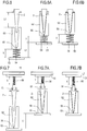
- the plant 10 has a medium- to low-productivity oven 5 of small size, where the branches of the path P, and hence the tunnels T1 and T2, extend for a short length.
- the zones where the parisons 2 feed in and out of the oven 5 are located on opposite sides of the same end of the path P of the oven 5.
- the first carousel 16 for transferring the parisons 2 from the moulding machine 1 to the oven 5 and the second carousel 17 for transferring the hot parisons 2 from the oven 5 to the blow-moulding 7 are located at one end of the oven 5.
- the parisons 2 pass through the two short tunnels T1 and T2 to be able to make the parisons 2 suitable for the subsequent blow-moulding stage, where the parisons 2 received by the oven are already warm since they come directly from the moulding machine.
- the stretch of the path coinciding with the two tunnels T1 and T2 allows the parisons 2 to be suitably cooled and transferred to the first conveyor 15.
- the zone of the conveyor which receives the parisons 2 is located between the end of the tunnel T2 and the zone where the parisons 2 are fed out to the second carousel 17 according to the feed direction P of the parisons 2.
- the first conveyor 15 in turn transfers the cooled parisons 2 to the buffer 14 (as indicated by the arrow FU in Figure 2 ).
- the second conveyor 15a connected to the buffer 14 (which the orienting device 18 is connected to) is configured to transfer the parisons 2 from the buffer 14 to the oven 5, when the heating means 6 are on during a machine shutdown period of the moulding machine 1.
- the second conveyor 15a can draw the parisons 2 stored in the buffer 14 and transfer them to the oven 5 operating in the heating configuration (as indicated by the arrow FE) so as not to interrupt feed to the blow-moulding machine 7 and thus keep the plant 10 in operation.
- the second conveyor 15a is configured to feed the first carousel 16 directly, that is to say, on the opposite side with respect to the unloading zone FU of the first conveyor 15.
- the plant 10 (as illustrated in Figure 1 ) comprises a high-productivity oven 5, with tunnels T1 and T2 extending for a great length.
- the first carousel 16 for transferring the parisons 2 from the moulding machine 1 to the oven 5 is located at a first end of the oven 5, while the unloading zone where the parisons 2 heated by the oven 5 are transferred to the second carousel 17 is located at the opposite end of the oven 5.
- the stretch of the path coinciding with the tunnel T2 allows the parisons 2 to be suitably cooled and transferred to the first conveyor 15.
- the first conveyor 15 in turn transfers the cooled parisons 2 to the buffer 14 (as indicated by the arrow FU in the drawing).
- the zone of the first conveyor 15 which receives the parisons 2 is located at the start of the tunnel T1.
- the second conveyor 15a is configured to transfer the parisons 2 from the buffer 14 to the oven 5, when the heating means 6 are on during a machine shutdown period of the moulding machine 1.
- the parison 2 unloading zone of the second conveyor 15a is located in the free zone at the end of the oven 5 near the second carousel 17 which transfers the parisons 2 to the blow-moulding machine.
- the second conveyor 15a can draw the parisons 2 stored in the buffer 14 and transfer them to the oven 5 operating in the heating configuration (as indicated by the arrow FE) so as not to interrupt feed to the blow-moulding machine 7 and thus keep the plant 10 in operation.
- the feeding of the parisons 2 is effected at a point of the path P such as to force the parisons 2 to go through both tunnels T1 and T2 (in a heating configuration) so that the parisons 2 fed are ready for blow-moulding.
- management unit 9 is connected to the buffer 14 and to the conveyors 15 and 15a and is programmed to control loading or unloading of the parisons 2 according to the working requirements of the machine.
- the unit 9 starts the automatic unloading of the parisons 2 from the oven 5 through the agency of the first conveyor 15 in response to a signal indicating that the blow-moulding machine 7 is shut down.
- the unit 9 starts the automatic feeding of the oven 5 with parisons 2 drawn from the buffer 14 through the agency of the second conveyor 15a, in response to a signal indicating that the moulding machine 1 is shut down.
- the oven 5 is configured to heat and cool different parisons 2 simultaneously.
- one of the tunnels (T1 or T2) of the oven 5 comprises the heating means 6 and the other tunnel (T2 or T1) of the oven 5 houses the cooling means 11 so as to define consecutive stretches of the oven 5 (first a heating stretch, followed by a cooling stretch, or vice versa).
- the heating and cooling means 9 and 11 may be positioned on two levels (heating above and cooling below, or vice versa).
- the invention also provides a method for making containers of thermoplastic material in continuous cycle.
- the method comprises the steps of:
- the method comprises a step of switching between the step of heating the parisons 2 in the oven 5 and a step of cooling the parisons 2 in the selfsame oven 5 during a shutdown period of the blow-moulding machine 7 and without interrupting the operation of the moulding machine 1.
- the method comprises a step of transferring into a buffer 14 the parisons 2 which have been cooled in the oven 5 during the period in which the blow-moulding machine 7 is shut down.
- the method further comprises a step of feeding the oven 5 with parisons 2 drawn from the buffer 14 during a period in which the parison moulding machine 1 is shut down.
- the step of cooling the parisons 2 in the oven 5 comprises generating a flow of cooling fluid directed along the inside and/or outside of the parisons 2.
- the oven 5 comprises elements 51 for picking up and transporting the parisons 2.
- the pickup and transporting elements 51 are connected to the conveyor 13 for transporting the parisons 2 along the predetermined path P within the oven 5.
- the oven 5 comprises a plurality of cooling cups 52. More specifically, the oven 5 comprises, for each pickup and transporting element 51, one cup 52 for cooling a respective parison 2 coupled thereto.
- the cups 52 and the pickup and transporting elements 51 are movable towards and away from each other
- the pickup and transporting elements 51 are movable towards and away from each other along a direction perpendicular to the predetermined path P (which preferably lies in a plane).
- the cups 52 are connected to respective movable carriers 53 to move from a distal position (away from the respective parisons 2) to a proximal position (relative to the respective parisons 2) where each parison 2 is at least partly inserted in the respective cup 52.
- the movable carriers 53 are connected to respective actuators (for example pneumatic or electric). These actuators are preferably connected to the management unit 9, or to another control unit, by which the movements of all the actuators are coordinated (as the parisons are loaded into the oven, when the oven is working in the cooling configuration).
- actuators for example pneumatic or electric.
- cup 52 defines a tapered seat in which the parisons 2 can be inserted and housed.
- the cups 52 are connected to the respective movable carriers 53 through the agency of springs 54. These springs are configured to work by compression.
- the springs 54 make the cups 52 elastically movable (along the direction of movement of cup 52 and parison 2 towards each other, in particular along an axis relative to which the cup 52 and the respective parison 2 are aligned) between a position proximal to the respective parisons 2 (where the springs 54 are at rest) and a position distal from the parisons, where the springs 54 are compressed.
- the cups 52 have respective suction channels 55 connected to suction means.
- the pickup and transporting elements 51 of the parisons 2 are connected to the conveyor 13 (preferably by respective spindles not illustrated) by springs 56. These springs are configured to work by compression.
- the springs 56 make the pickup and transporting elements 51 (and hence the parisons 2 coupled thereto) elastically movable (along the direction of movement of cup 52 and parison 2 towards each other, in particular along the axis relative to which the cup 52 and the respective parison 2 are aligned) between a position proximal to the respective cups 52 (where the springs 56 are at rest) and a position distal from the cups 52, where the springs 56 are compressed.
- the stroke L1 (assigned to the cup 52 in the examples illustrated) would cause the parison 2 to be inserted completely in the cup 52.
- the spring 54 or 56 is compressed and its length is reduced from X (the length of the spring at rest) to Y, where Y is less than X.
Landscapes
- Engineering & Computer Science (AREA)
- Manufacturing & Machinery (AREA)
- Mechanical Engineering (AREA)
- Physics & Mathematics (AREA)
- Thermal Sciences (AREA)
- Blow-Moulding Or Thermoforming Of Plastics Or The Like (AREA)
- Moulds For Moulding Plastics Or The Like (AREA)
Claims (13)
- Installation pour la fabrication de récipients en matière thermoplastique en cycle continu comprenant :- une machine à mouler (1) configurée pour réaliser des paraisons (2) de matière thermoplastique comportant un corps (3) doté d'un fond fermé et d'un goulot (4) définissant une ouverture ;- un four de chauffage (5) configuré pour recevoir les paraisons (2) sortant de la machine à mouler (1) et équipé de moyens de chauffage (6) agissant sur les corps (3) des paraisons (2), dans laquelle le four (5) comporte un convoyeur (13) configuré pour transporter les paraisons (2) le long d'un parcours prédéterminé à l'intérieur du four (5) ;- une machine à mouler par soufflage (7) configurée pour recevoir les paraisons (2) chauffées dans le four (5) et pour les mouler par soufflage dans des moules (8) pour réaliser les récipients, caractérisée en ce qu'elle comprend une unité de gestion (9) d'installation (10) configurée pour éteindre ou pour réduire la puissance de chauffage des moyens de chauffage (6) du four (5) et pour maintenir le convoyeur (13) en fonctionnement pendant une période au cours de laquelle la machine à mouler par soufflage (7) est à l'arrêt, dans laquelle l'unité de gestion (9) est configurée pour maintenir la machine à mouler (1) en fonctionnement pendant ladite période lorsque la machine à mouler par soufflage (7) est à l'arrêt, par laquelle les paraisons (2) situées dans le four (5) peuvent se refroidir lors de leur transit à travers le four (5), et dans laquelle l'installation (1) comprend un stock tampon (14) relié au four (5) par un convoyeur (15) étant configuré pour transférer au stock tampon (14) les paraisons (2) refroidies par le four (5) lorsque le four (5) est dans une configuration de refroidissement où les moyens de chauffage (6) sont éteints ou fonctionnent à faible chaleur.
- Installation selon la revendication 1, dans laquelle l'unité de gestion (9) est configurée pour éteindre ou pour réduire la puissance de chauffage des moyens de chauffage (6) du four (5) en réponse à un signal d'arrêt de la machine provenant de la machine à mouler par soufflage (7).
- Installation selon la revendication 1 ou 2, dans laquelle le four (5) comprend des moyens de refroidissement (11) agissant sur les paraisons (2), et dans laquelle l'unité de gestion (9) comprend un sélecteur (12) configuré pour allumer le four (5) entre une configuration de chauffage où les moyens de chauffage (6) sont allumés et les moyens de refroidissement (11) sont éteints, et une configuration de refroidissement où les moyens de chauffage (6) sont éteints ou fonctionnent à faible chaleur et les moyens de refroidissement (11) sont allumés.
- Installation selon la revendication 3, dans laquelle les moyens de refroidissement (11) comprennent une pluralité de buses (11a) configurées pour frapper les paraisons (2) avec un flux (F) de fluide de refroidissement le long au moins d'une portion d'un parcours prédéfini (P) des paraisons (2).
- Installation selon la revendication 4, dans laquelle les paraisons (2) sont déplacées le long du parcours (P) par une combinaison d'un mouvement conféré par le convoyeur (13) le long du parcours (P) et d'une rotation de chaque paraison (2) autour d'un axe (Z) d'extension de la même paraison (2), dans laquelle au moins une des buses (11) est montée parallèlement au dit axe (Z) de manière à orienter le fluide de refroidissement axialement le long des paraisons.
- Installation selon l'une quelconque des revendications précédentes, dans laquelle le four (5) comprend un carrousel tournant autour d'un axe.
- Installation selon l'une quelconque des revendications précédentes, dans laquelle l'unité de gestion (9) est reliée à la machine à mouler par soufflage (7) et au four (5) et est programmée pour recevoir un signal représentant le fonctionnement de la machine à mouler par soufflage (7) afin d'éteindre ou de réduire la puissance de chauffage des moyens de chauffage (6) du four (5) automatiquement en réponse à un signal d'arrêt de la machine à mouler par soufflage (7).
- Installation selon l'une quelconque des revendications précédentes, dans laquelle le stock tampon (14) est relié au four (5) par un second convoyeur (15a) indépendant du premier convoyeur (15) et configuré pour transférer les paraisons (2) du stock tampon (14) vers le four (5) lorsque le four (5) est dans une configuration de refroidissement lors d'une période d'arrêt de la machine à mouler (1).
- Installation selon la revendication 8, dans laquelle l'unité de gestion (9) est reliée au stock tampon (14) et au second convoyeur (15a) et est programmée pour automatiquement activer le four (5) alimenté avec des paraisons (2) tiré du stock tampon (14), en réponse à un signal d'arrêt provenant de la machine à mouler des paraisons (1).
- Installation selon la revendication 8 ou 9, comprenant un dispositif d'orientation (18) des paraisons situé entre le stock tampon (14) et le four (5) pour positionner les paraisons (2) tirées du stock tampon (14) sur le second convoyeur (15a) selon une orientation prédéfinie.
- Procédé pour la fabrication de récipients en matière thermoplastique en cycle continu comprenant les étapes suivantes :- mouler une matière thermoplastique dans une machine à mouler (1) pour réaliser des paraisons (2) comportant un corps (3) doté d'un fond fermé et d'un goulot (4) définissant une ouverture ;- chauffer dans un four (5) les paraisons (2) sortant de la machine à mouler (1), dans laquelle le four (5) comporte un convoyeur (13) configuré pour transporter les paraisons (2) le long d'un parcours prédéterminé à l'intérieur du four (5) ;- mouler par soufflage dans des moules (8) les paraisons (2) chauffées dans le four (5), caractérisé en ce qu'il comprend une étape de commutation entre l'étape de chauffage des paraisons (2) dans le four (5) et une étape de refroidissement, ou de réduction significative du chauffage des paraisons (2) dans le même four (5) lors d'une période d'arrêt de la machine à mouler par soufflage (7), en maintenant le convoyeur (13) et la machine à mouler (1) en fonctionnement, dans lequel le procédé comprend une étape consistant à transférer dans un stock tampon (14) les paraisons (2) ayant été refroidies dans le four (5) lors de la période pendant laquelle la machine à mouler par soufflage (7) est à l'arrêt.
- Procédé selon la revendication 11, comprenant une étape consistant à alimenter le four (5) avec des paraisons (2) tirées du stock tampon (14) lors d'une période durant laquelle la machine à mouler des paraisons (1) est à l'arrêt.
- Procédé selon l'une quelconque des revendications de 11 à 12, dans lequel le four (5) comprend un carrousel qui tourne autour d'un axe.
Applications Claiming Priority (2)
| Application Number | Priority Date | Filing Date | Title |
|---|---|---|---|
| IT000690A ITBO20110690A1 (it) | 2011-12-02 | 2011-12-02 | Impianto per la realizzazione di contenitori in materiale termoplastico. |
| PCT/IB2012/056861 WO2013080171A1 (fr) | 2011-12-02 | 2012-11-30 | Installation permettant de réaliser des récipients en matériau thermoplastique |
Publications (2)
| Publication Number | Publication Date |
|---|---|
| EP2785509A1 EP2785509A1 (fr) | 2014-10-08 |
| EP2785509B1 true EP2785509B1 (fr) | 2018-04-04 |
Family
ID=45571592
Family Applications (1)
| Application Number | Title | Priority Date | Filing Date |
|---|---|---|---|
| EP12806701.4A Active EP2785509B1 (fr) | 2011-12-02 | 2012-11-30 | Installation pour la fabrication de récipients en matière plastique |
Country Status (7)
| Country | Link |
|---|---|
| US (1) | US9636862B2 (fr) |
| EP (1) | EP2785509B1 (fr) |
| CN (1) | CN104053534B (fr) |
| ES (1) | ES2674931T3 (fr) |
| IT (1) | ITBO20110690A1 (fr) |
| TR (1) | TR201809024T4 (fr) |
| WO (1) | WO2013080171A1 (fr) |
Families Citing this family (1)
| Publication number | Priority date | Publication date | Assignee | Title |
|---|---|---|---|---|
| IT201900010416A1 (it) * | 2019-06-28 | 2020-12-28 | Sacmi | Dispositivo di ispezione ottica di preforme |
Family Cites Families (12)
| Publication number | Priority date | Publication date | Assignee | Title |
|---|---|---|---|---|
| US3995990A (en) * | 1974-03-11 | 1976-12-07 | Monsanto Company | Pre-form reheat oven for stretch blow molding machines |
| US4059188A (en) * | 1976-03-18 | 1977-11-22 | Cincinnati Milacron Inc. | Manual preform removal device |
| US4449913A (en) * | 1981-02-23 | 1984-05-22 | The Continental Group, Inc. | Rotary injection turret for the making of preforms |
| US4571173A (en) * | 1982-05-14 | 1986-02-18 | Owens-Illinois, Inc. | Method for thermally conditioning a thermoplastic preform |
| CH690543A5 (fr) * | 1995-07-19 | 2000-10-13 | Tetra Pak Plastics Ltd Tetra P | Machines pour la fabrication de récipients en matière plastique. |
| US6620352B1 (en) * | 2000-07-27 | 2003-09-16 | Ball Corporation | Automated material distribution control for stretch blow molded articles |
| DE10145456A1 (de) | 2001-09-14 | 2003-05-22 | Krones Ag | Vorrichtung zum Erwärmen von mit einem Tragring versehenen Vorformlingen |
| DE102006049163A1 (de) * | 2006-10-18 | 2008-05-08 | Sig Technology Ag | Verfahren und Vorrichtung zur Blasformung von Behältern |
| RU2010147001A (ru) | 2008-04-18 | 2012-05-27 | Сакми Кооператива Мекканичи Имола Сочьета'Кооператива (It) | Устройство и способ формования пластика |
| FR2932353B1 (fr) * | 2008-06-09 | 2010-07-30 | Olilab Llc | Dispositif et procede de commande de fours a lampes infrarouges |
| FR2938789B1 (fr) * | 2008-11-24 | 2013-03-29 | Gregoire Lize | Procede et dispositif de chauffage par infrarouge de preformes plastiques. |
| IT1395015B1 (it) | 2009-06-30 | 2012-09-05 | Sacmi | Apparato di riscaldamento di preforme in materiale termoplastico. |
-
2011
- 2011-12-02 IT IT000690A patent/ITBO20110690A1/it unknown
-
2012
- 2012-11-30 TR TR2018/09024T patent/TR201809024T4/tr unknown
- 2012-11-30 US US14/361,781 patent/US9636862B2/en active Active
- 2012-11-30 CN CN201280059426.3A patent/CN104053534B/zh active Active
- 2012-11-30 WO PCT/IB2012/056861 patent/WO2013080171A1/fr active Application Filing
- 2012-11-30 EP EP12806701.4A patent/EP2785509B1/fr active Active
- 2012-11-30 ES ES12806701.4T patent/ES2674931T3/es active Active
Also Published As
| Publication number | Publication date |
|---|---|
| EP2785509A1 (fr) | 2014-10-08 |
| WO2013080171A1 (fr) | 2013-06-06 |
| ITBO20110690A1 (it) | 2013-06-03 |
| US20140327189A1 (en) | 2014-11-06 |
| US9636862B2 (en) | 2017-05-02 |
| ES2674931T3 (es) | 2018-07-05 |
| TR201809024T4 (tr) | 2018-07-23 |
| CN104053534A (zh) | 2014-09-17 |
| CN104053534B (zh) | 2016-12-14 |
Similar Documents
| Publication | Publication Date | Title |
|---|---|---|
| KR100356306B1 (ko) | 라인식병담기설비 | |
| EP2315654B1 (fr) | Installation pour le moulage par soufflage de contenants en plastique, notamment de bouteilles | |
| EP2307183B1 (fr) | Installation et procede pour le moulage par soufflage de contenants en plastique, notamment de bouteilles | |
| RU2007110792A (ru) | Выдувная машина и способ изготовления бутылок или подобных полых тел | |
| WO2009127962A4 (fr) | Procédé et appareils | |
| EP2318196B1 (fr) | Unité de moulage pour équipement de moulage par soufflage de récipients en plastique, en particulier des bouteilles | |
| CN110494267B (zh) | 具有主动式预成型件夹紧装置的快速更换芯轴 | |
| EP2785509B1 (fr) | Installation pour la fabrication de récipients en matière plastique | |
| CN112955299B (zh) | 加热站中不动的预成型件的管理方法和设备 | |
| US20110138594A1 (en) | Plant for blow-moulding plastic containers, particularly bottles | |
| CN112969566B (zh) | 生产中断后在加热站中不动的预成型件的管理方法 | |
| CN112074392B (zh) | 用分离的驱动器将塑料预成型件成型为塑料容器的设备 | |
| ES2702938T3 (es) | Máquina para moldear y moldear por soplado recipientes obtenidos de preformas correspondientes de un material termoplástico | |
| US11667056B2 (en) | Injection moulding machine for continuous production | |
| CN113260496B (zh) | 用于炉的预成型件输送设备和这种设备的控制方法 | |
| WO2012066459A1 (fr) | Appareil et procédé de chauffage de paraisons de matériau thermoplastique | |
| CN102325641A (zh) | 用气体加热的瓶坯加热器、方法和设备 |
Legal Events
| Date | Code | Title | Description |
|---|---|---|---|
| PUAI | Public reference made under article 153(3) epc to a published international application that has entered the european phase |
Free format text: ORIGINAL CODE: 0009012 |
|
| 17P | Request for examination filed |
Effective date: 20140627 |
|
| AK | Designated contracting states |
Kind code of ref document: A1 Designated state(s): AL AT BE BG CH CY CZ DE DK EE ES FI FR GB GR HR HU IE IS IT LI LT LU LV MC MK MT NL NO PL PT RO RS SE SI SK SM TR |
|
| DAX | Request for extension of the european patent (deleted) | ||
| 17Q | First examination report despatched |
Effective date: 20170407 |
|
| GRAP | Despatch of communication of intention to grant a patent |
Free format text: ORIGINAL CODE: EPIDOSNIGR1 |
|
| INTG | Intention to grant announced |
Effective date: 20171115 |
|
| GRAS | Grant fee paid |
Free format text: ORIGINAL CODE: EPIDOSNIGR3 |
|
| GRAA | (expected) grant |
Free format text: ORIGINAL CODE: 0009210 |
|
| AK | Designated contracting states |
Kind code of ref document: B1 Designated state(s): AL AT BE BG CH CY CZ DE DK EE ES FI FR GB GR HR HU IE IS IT LI LT LU LV MC MK MT NL NO PL PT RO RS SE SI SK SM TR |
|
| REG | Reference to a national code |
Ref country code: GB Ref legal event code: FG4D |
|
| REG | Reference to a national code |
Ref country code: CH Ref legal event code: EP |
|
| REG | Reference to a national code |
Ref country code: AT Ref legal event code: REF Ref document number: 985136 Country of ref document: AT Kind code of ref document: T Effective date: 20180415 |
|
| REG | Reference to a national code |
Ref country code: DE Ref legal event code: R096 Ref document number: 602012044836 Country of ref document: DE |
|
| REG | Reference to a national code |
Ref country code: IE Ref legal event code: FG4D |
|
| REG | Reference to a national code |
Ref country code: ES Ref legal event code: FG2A Ref document number: 2674931 Country of ref document: ES Kind code of ref document: T3 Effective date: 20180705 |
|
| REG | Reference to a national code |
Ref country code: NL Ref legal event code: MP Effective date: 20180404 |
|
| REG | Reference to a national code |
Ref country code: LT Ref legal event code: MG4D |
|
| PG25 | Lapsed in a contracting state [announced via postgrant information from national office to epo] |
Ref country code: NL Free format text: LAPSE BECAUSE OF FAILURE TO SUBMIT A TRANSLATION OF THE DESCRIPTION OR TO PAY THE FEE WITHIN THE PRESCRIBED TIME-LIMIT Effective date: 20180404 |
|
| REG | Reference to a national code |
Ref country code: FR Ref legal event code: PLFP Year of fee payment: 7 |
|
| PG25 | Lapsed in a contracting state [announced via postgrant information from national office to epo] |
Ref country code: AL Free format text: LAPSE BECAUSE OF FAILURE TO SUBMIT A TRANSLATION OF THE DESCRIPTION OR TO PAY THE FEE WITHIN THE PRESCRIBED TIME-LIMIT Effective date: 20180404 Ref country code: SE Free format text: LAPSE BECAUSE OF FAILURE TO SUBMIT A TRANSLATION OF THE DESCRIPTION OR TO PAY THE FEE WITHIN THE PRESCRIBED TIME-LIMIT Effective date: 20180404 Ref country code: PL Free format text: LAPSE BECAUSE OF FAILURE TO SUBMIT A TRANSLATION OF THE DESCRIPTION OR TO PAY THE FEE WITHIN THE PRESCRIBED TIME-LIMIT Effective date: 20180404 Ref country code: NO Free format text: LAPSE BECAUSE OF FAILURE TO SUBMIT A TRANSLATION OF THE DESCRIPTION OR TO PAY THE FEE WITHIN THE PRESCRIBED TIME-LIMIT Effective date: 20180704 Ref country code: BG Free format text: LAPSE BECAUSE OF FAILURE TO SUBMIT A TRANSLATION OF THE DESCRIPTION OR TO PAY THE FEE WITHIN THE PRESCRIBED TIME-LIMIT Effective date: 20180704 Ref country code: LT Free format text: LAPSE BECAUSE OF FAILURE TO SUBMIT A TRANSLATION OF THE DESCRIPTION OR TO PAY THE FEE WITHIN THE PRESCRIBED TIME-LIMIT Effective date: 20180404 Ref country code: FI Free format text: LAPSE BECAUSE OF FAILURE TO SUBMIT A TRANSLATION OF THE DESCRIPTION OR TO PAY THE FEE WITHIN THE PRESCRIBED TIME-LIMIT Effective date: 20180404 |
|
| PG25 | Lapsed in a contracting state [announced via postgrant information from national office to epo] |
Ref country code: RS Free format text: LAPSE BECAUSE OF FAILURE TO SUBMIT A TRANSLATION OF THE DESCRIPTION OR TO PAY THE FEE WITHIN THE PRESCRIBED TIME-LIMIT Effective date: 20180404 Ref country code: HR Free format text: LAPSE BECAUSE OF FAILURE TO SUBMIT A TRANSLATION OF THE DESCRIPTION OR TO PAY THE FEE WITHIN THE PRESCRIBED TIME-LIMIT Effective date: 20180404 Ref country code: LV Free format text: LAPSE BECAUSE OF FAILURE TO SUBMIT A TRANSLATION OF THE DESCRIPTION OR TO PAY THE FEE WITHIN THE PRESCRIBED TIME-LIMIT Effective date: 20180404 Ref country code: GR Free format text: LAPSE BECAUSE OF FAILURE TO SUBMIT A TRANSLATION OF THE DESCRIPTION OR TO PAY THE FEE WITHIN THE PRESCRIBED TIME-LIMIT Effective date: 20180705 |
|
| PG25 | Lapsed in a contracting state [announced via postgrant information from national office to epo] |
Ref country code: PT Free format text: LAPSE BECAUSE OF FAILURE TO SUBMIT A TRANSLATION OF THE DESCRIPTION OR TO PAY THE FEE WITHIN THE PRESCRIBED TIME-LIMIT Effective date: 20180806 |
|
| REG | Reference to a national code |
Ref country code: DE Ref legal event code: R097 Ref document number: 602012044836 Country of ref document: DE |
|
| PG25 | Lapsed in a contracting state [announced via postgrant information from national office to epo] |
Ref country code: CZ Free format text: LAPSE BECAUSE OF FAILURE TO SUBMIT A TRANSLATION OF THE DESCRIPTION OR TO PAY THE FEE WITHIN THE PRESCRIBED TIME-LIMIT Effective date: 20180404 Ref country code: RO Free format text: LAPSE BECAUSE OF FAILURE TO SUBMIT A TRANSLATION OF THE DESCRIPTION OR TO PAY THE FEE WITHIN THE PRESCRIBED TIME-LIMIT Effective date: 20180404 Ref country code: SK Free format text: LAPSE BECAUSE OF FAILURE TO SUBMIT A TRANSLATION OF THE DESCRIPTION OR TO PAY THE FEE WITHIN THE PRESCRIBED TIME-LIMIT Effective date: 20180404 Ref country code: DK Free format text: LAPSE BECAUSE OF FAILURE TO SUBMIT A TRANSLATION OF THE DESCRIPTION OR TO PAY THE FEE WITHIN THE PRESCRIBED TIME-LIMIT Effective date: 20180404 Ref country code: EE Free format text: LAPSE BECAUSE OF FAILURE TO SUBMIT A TRANSLATION OF THE DESCRIPTION OR TO PAY THE FEE WITHIN THE PRESCRIBED TIME-LIMIT Effective date: 20180404 |
|
| PLBE | No opposition filed within time limit |
Free format text: ORIGINAL CODE: 0009261 |
|
| STAA | Information on the status of an ep patent application or granted ep patent |
Free format text: STATUS: NO OPPOSITION FILED WITHIN TIME LIMIT |
|
| PG25 | Lapsed in a contracting state [announced via postgrant information from national office to epo] |
Ref country code: SM Free format text: LAPSE BECAUSE OF FAILURE TO SUBMIT A TRANSLATION OF THE DESCRIPTION OR TO PAY THE FEE WITHIN THE PRESCRIBED TIME-LIMIT Effective date: 20180404 |
|
| 26N | No opposition filed |
Effective date: 20190107 |
|
| PG25 | Lapsed in a contracting state [announced via postgrant information from national office to epo] |
Ref country code: SI Free format text: LAPSE BECAUSE OF FAILURE TO SUBMIT A TRANSLATION OF THE DESCRIPTION OR TO PAY THE FEE WITHIN THE PRESCRIBED TIME-LIMIT Effective date: 20180404 |
|
| REG | Reference to a national code |
Ref country code: CH Ref legal event code: PL |
|
| GBPC | Gb: european patent ceased through non-payment of renewal fee |
Effective date: 20181130 |
|
| PG25 | Lapsed in a contracting state [announced via postgrant information from national office to epo] |
Ref country code: MC Free format text: LAPSE BECAUSE OF FAILURE TO SUBMIT A TRANSLATION OF THE DESCRIPTION OR TO PAY THE FEE WITHIN THE PRESCRIBED TIME-LIMIT Effective date: 20180404 Ref country code: LU Free format text: LAPSE BECAUSE OF NON-PAYMENT OF DUE FEES Effective date: 20181130 |
|
| REG | Reference to a national code |
Ref country code: BE Ref legal event code: MM Effective date: 20181130 |
|
| REG | Reference to a national code |
Ref country code: IE Ref legal event code: MM4A |
|
| PG25 | Lapsed in a contracting state [announced via postgrant information from national office to epo] |
Ref country code: LI Free format text: LAPSE BECAUSE OF NON-PAYMENT OF DUE FEES Effective date: 20181130 Ref country code: CH Free format text: LAPSE BECAUSE OF NON-PAYMENT OF DUE FEES Effective date: 20181130 |
|
| PG25 | Lapsed in a contracting state [announced via postgrant information from national office to epo] |
Ref country code: IE Free format text: LAPSE BECAUSE OF NON-PAYMENT OF DUE FEES Effective date: 20181130 |
|
| PG25 | Lapsed in a contracting state [announced via postgrant information from national office to epo] |
Ref country code: BE Free format text: LAPSE BECAUSE OF NON-PAYMENT OF DUE FEES Effective date: 20181130 |
|
| PG25 | Lapsed in a contracting state [announced via postgrant information from national office to epo] |
Ref country code: GB Free format text: LAPSE BECAUSE OF NON-PAYMENT OF DUE FEES Effective date: 20181130 |
|
| PG25 | Lapsed in a contracting state [announced via postgrant information from national office to epo] |
Ref country code: MT Free format text: LAPSE BECAUSE OF NON-PAYMENT OF DUE FEES Effective date: 20181130 |
|
| PG25 | Lapsed in a contracting state [announced via postgrant information from national office to epo] |
Ref country code: HU Free format text: LAPSE BECAUSE OF FAILURE TO SUBMIT A TRANSLATION OF THE DESCRIPTION OR TO PAY THE FEE WITHIN THE PRESCRIBED TIME-LIMIT; INVALID AB INITIO Effective date: 20121130 Ref country code: CY Free format text: LAPSE BECAUSE OF FAILURE TO SUBMIT A TRANSLATION OF THE DESCRIPTION OR TO PAY THE FEE WITHIN THE PRESCRIBED TIME-LIMIT Effective date: 20180404 Ref country code: MK Free format text: LAPSE BECAUSE OF NON-PAYMENT OF DUE FEES Effective date: 20180404 |
|
| PG25 | Lapsed in a contracting state [announced via postgrant information from national office to epo] |
Ref country code: IS Free format text: LAPSE BECAUSE OF FAILURE TO SUBMIT A TRANSLATION OF THE DESCRIPTION OR TO PAY THE FEE WITHIN THE PRESCRIBED TIME-LIMIT Effective date: 20180804 |
|
| REG | Reference to a national code |
Ref country code: AT Ref legal event code: UEP Ref document number: 985136 Country of ref document: AT Kind code of ref document: T Effective date: 20180404 |
|
| P01 | Opt-out of the competence of the unified patent court (upc) registered |
Effective date: 20230527 |
|
| PGFP | Annual fee paid to national office [announced via postgrant information from national office to epo] |
Ref country code: ES Payment date: 20231201 Year of fee payment: 12 |
|
| PGFP | Annual fee paid to national office [announced via postgrant information from national office to epo] |
Ref country code: TR Payment date: 20231026 Year of fee payment: 12 Ref country code: IT Payment date: 20231019 Year of fee payment: 12 Ref country code: FR Payment date: 20231019 Year of fee payment: 12 Ref country code: DE Payment date: 20231019 Year of fee payment: 12 Ref country code: AT Payment date: 20231023 Year of fee payment: 12 |