EP2785472B2 - Device for classifying grainy products - Google Patents
Device for classifying grainy products Download PDFInfo
- Publication number
- EP2785472B2 EP2785472B2 EP12790561.0A EP12790561A EP2785472B2 EP 2785472 B2 EP2785472 B2 EP 2785472B2 EP 12790561 A EP12790561 A EP 12790561A EP 2785472 B2 EP2785472 B2 EP 2785472B2
- Authority
- EP
- European Patent Office
- Prior art keywords
- separator
- housing
- static
- accordance
- dynamic
- Prior art date
- Legal status (The legal status is an assumption and is not a legal conclusion. Google has not performed a legal analysis and makes no representation as to the accuracy of the status listed.)
- Active
Links
Images
Classifications
-
- B—PERFORMING OPERATIONS; TRANSPORTING
- B07—SEPARATING SOLIDS FROM SOLIDS; SORTING
- B07B—SEPARATING SOLIDS FROM SOLIDS BY SIEVING, SCREENING, SIFTING OR BY USING GAS CURRENTS; SEPARATING BY OTHER DRY METHODS APPLICABLE TO BULK MATERIAL, e.g. LOOSE ARTICLES FIT TO BE HANDLED LIKE BULK MATERIAL
- B07B4/00—Separating solids from solids by subjecting their mixture to gas currents
- B07B4/08—Separating solids from solids by subjecting their mixture to gas currents while the mixtures are supported by sieves, screens, or like mechanical elements
-
- B—PERFORMING OPERATIONS; TRANSPORTING
- B02—CRUSHING, PULVERISING, OR DISINTEGRATING; PREPARATORY TREATMENT OF GRAIN FOR MILLING
- B02C—CRUSHING, PULVERISING, OR DISINTEGRATING IN GENERAL; MILLING GRAIN
- B02C21/00—Disintegrating plant with or without drying of the material
- B02C21/002—Disintegrating plant with or without drying of the material using a combination of a roller mill and a drum mill
- B02C21/005—Disintegrating plant with or without drying of the material using a combination of a roller mill and a drum mill the roller mill having cooperating rollers
-
- B—PERFORMING OPERATIONS; TRANSPORTING
- B02—CRUSHING, PULVERISING, OR DISINTEGRATING; PREPARATORY TREATMENT OF GRAIN FOR MILLING
- B02C—CRUSHING, PULVERISING, OR DISINTEGRATING IN GENERAL; MILLING GRAIN
- B02C23/00—Auxiliary methods or auxiliary devices or accessories specially adapted for crushing or disintegrating not provided for in preceding groups or not specially adapted to apparatus covered by a single preceding group
- B02C23/08—Separating or sorting of material, associated with crushing or disintegrating
- B02C23/10—Separating or sorting of material, associated with crushing or disintegrating with separator arranged in discharge path of crushing or disintegrating zone
- B02C23/12—Separating or sorting of material, associated with crushing or disintegrating with separator arranged in discharge path of crushing or disintegrating zone with return of oversize material to crushing or disintegrating zone
-
- B—PERFORMING OPERATIONS; TRANSPORTING
- B02—CRUSHING, PULVERISING, OR DISINTEGRATING; PREPARATORY TREATMENT OF GRAIN FOR MILLING
- B02C—CRUSHING, PULVERISING, OR DISINTEGRATING IN GENERAL; MILLING GRAIN
- B02C23/00—Auxiliary methods or auxiliary devices or accessories specially adapted for crushing or disintegrating not provided for in preceding groups or not specially adapted to apparatus covered by a single preceding group
- B02C23/08—Separating or sorting of material, associated with crushing or disintegrating
- B02C23/14—Separating or sorting of material, associated with crushing or disintegrating with more than one separator
-
- B—PERFORMING OPERATIONS; TRANSPORTING
- B07—SEPARATING SOLIDS FROM SOLIDS; SORTING
- B07B—SEPARATING SOLIDS FROM SOLIDS BY SIEVING, SCREENING, SIFTING OR BY USING GAS CURRENTS; SEPARATING BY OTHER DRY METHODS APPLICABLE TO BULK MATERIAL, e.g. LOOSE ARTICLES FIT TO BE HANDLED LIKE BULK MATERIAL
- B07B4/00—Separating solids from solids by subjecting their mixture to gas currents
- B07B4/02—Separating solids from solids by subjecting their mixture to gas currents while the mixtures fall
- B07B4/04—Separating solids from solids by subjecting their mixture to gas currents while the mixtures fall in cascades
-
- B—PERFORMING OPERATIONS; TRANSPORTING
- B07—SEPARATING SOLIDS FROM SOLIDS; SORTING
- B07B—SEPARATING SOLIDS FROM SOLIDS BY SIEVING, SCREENING, SIFTING OR BY USING GAS CURRENTS; SEPARATING BY OTHER DRY METHODS APPLICABLE TO BULK MATERIAL, e.g. LOOSE ARTICLES FIT TO BE HANDLED LIKE BULK MATERIAL
- B07B7/00—Selective separation of solid materials carried by, or dispersed in, gas currents
- B07B7/08—Selective separation of solid materials carried by, or dispersed in, gas currents using centrifugal force
- B07B7/083—Selective separation of solid materials carried by, or dispersed in, gas currents using centrifugal force generated by rotating vanes, discs, drums, or brushes
-
- B—PERFORMING OPERATIONS; TRANSPORTING
- B07—SEPARATING SOLIDS FROM SOLIDS; SORTING
- B07B—SEPARATING SOLIDS FROM SOLIDS BY SIEVING, SCREENING, SIFTING OR BY USING GAS CURRENTS; SEPARATING BY OTHER DRY METHODS APPLICABLE TO BULK MATERIAL, e.g. LOOSE ARTICLES FIT TO BE HANDLED LIKE BULK MATERIAL
- B07B9/00—Combinations of apparatus for screening or sifting or for separating solids from solids using gas currents; General arrangement of plant, e.g. flow sheets
- B07B9/02—Combinations of similar or different apparatus for separating solids from solids using gas currents
Definitions
- the granular material to be sifted can be, for example, cement, cement-containing materials, cement raw material, limestone or slag, but also ores or the like.
- roller presses or material bed roller mills are used in particular to crush such granular materials.
- this high-pressure crushing of the granular material to be ground it is crushed in the gap between two press rollers (material bed crushing).
- material bed crushing During the crushing process, agglomerates are formed, which are referred to as flakes.
- Material bed roller mills of this type can be operated in a closed circuit with a static and/or dynamic sifter.
- the material bed roller mill is then positioned below a sifter, for example, so that the coarse material fraction emerging from the sifter is (re)fed to the roller mill.
- the material emerging from the roller mill is in turn fed to the material inlet of the classifying device, which is a multi-stage device consisting of a static classifier and a dynamic classifier.
- the static classifier the slugs are deagglomerated via the impact and guide elements, and at the same time the coarse material fraction is separated and fed to the roller press.
- the "finer" material enters the dynamic classifier with the classifying gases, where it is subjected to fine classification.
- the fine material classified from this classifier is discharged together with the classifying gas and collected as finished product in the following cyclones and/or filters.
- the middle fraction classified from the dynamic classifier can, for example, also be fed back to the roller press or to another grinding stage.
- Such measures are known from the state of the art (see, for example, DE 43 37 215 A1
- a generic viewing device of the type described above is known, for example, from the DE 42 23 762 B4
- This sifting device has a rotating rod basket in a housing with turbo elements distributed around the circumference of the rotor and with inlets and outlets for sifting air, sifting material, fines, medium material and coarse material.
- a shaft-shaped screening chamber is arranged at the same height on the side in front of the horizontally arranged rod basket, which has an inlet opening for the sifting material at the top that is separate from the sifting air, an opening for the sifting air arranged opposite the rod basket at the side, a discharge opening for a sifted coarse grain fraction at the bottom and two opposing shaft boundary walls that form a screening zone between them and are permeable to the sifting air.
- These shaft boundary walls of the screening chamber that are permeable to the sifting air have blind-like guide plates that are inclined diagonally downwards in the direction of the discharge opening for the sifted coarse material fraction, which act as impact and guide fittings and also ensure deagglomeration of the slugs.
- the sifting device consists of several concentric housings, with a rod basket rotating around a vertical axis serving as the secondary sifting stage.
- the secondary sifting stage is formed by a simple cyclone, with the sifting material and the sifting gas being fed in via a common feed line that is connected in a spiral to the sifter housing. Deagglomeration of the slugs is only possible to a limited extent in the static sifting stage.
- a device for classifying granular material into at least three grain fractions with a static classifier and a dynamic classifier, which are arranged rotationally symmetrically about a common axis in a common housing.
- the EN 10 2006 039 775 A1 a special design sifter with static Cascade sifter and a further sifter known as a post-sifter, wherein the cascade sifter has two packages of cone rings arranged spaced apart one above the other and concentrically to one another.
- the DD253771A1 an air classifier for classifying fine-grained bulk materials in particular into at least two fractions, consisting of a cylindrical upper housing section, which is followed at the bottom by a semolina cone with semolina discharge.
- the rod basket rotates around a vertical axis. The aim is to improve the distribution of the material in the classifying chamber of classifiers with rod baskets so that the separation accuracy is increased and the energy consumption, related to the end product, is reduced, regardless of the speed and shape of a spreading plate.
- a ring container with a fluidizing bottom is provided as a dispersing device, which is arranged above the classifying gas inlet nozzle in the area of the rod basket inside or outside the classifier housing and is connected to the classifying chamber via an annular gap and/or an annular channel.
- the invention is therefore based on the object of creating a device for classifying granular material into at least three fractions of the type described at the beginning, which is characterized not only by a particularly compact structure, but also in particular by low investment and operating costs and higher classifying efficiency.
- a classifying device should enable economical operation of a grinding plant with at least one roller press with high classifying efficiency.
- the invention provides a device for sifting granular material into at least three fractions, which has the features of claim 1.
- the invention is based first of all on the fundamentally known finding that it is advantageous to combine a static sifter and a dynamic sifter in the form of a rod basket sifter, since a first coarse material fraction can be sifted out via the static sifter, so that the dynamic sifter with the relatively sensitive rotating components is not unnecessarily burdened with coarse material.
- the static and dynamic sifters are combined in a particularly efficient and compact design by using a rod basket with a vertical axis of rotation and by connecting the static sifter directly to the side of the dynamic sifter, with the static sifter fulfilling both the task of slug deagglomeration and a first coarse separation in terms of process technology.
- the static sifter and dynamic sifter are therefore brought spatially close together so that both sifters work particularly efficiently in terms of energy, and the static sifter can simultaneously fulfill the task of slug deagglomeration.
- the sifter housing of the static sifter opens into the sifter housing of the dynamic sifter in a tangential or spiral orientation.
- the sifter housing of the static sifter is always compactly connected laterally to the sifter housing of the dynamic sifter, so that the static sifter housing merges into the dynamic sifter housing.
- the sifter according to the invention therefore has housing areas which can be assigned to both the static sifter and the dynamic sifter as a transition between the static sifter and the dynamic sifter.
- the sifter housing of the dynamic sifter has an upper housing section in which the rotating rod basket is arranged, and a lower housing section in which a discharge funnel for the middle material is arranged, the static sifter being connected with its housing to the lower housing section of the dynamic sifter and merging into this lower housing section.
- This lower housing section of the dynamic sifter therefore forms the transition area between the static sifter and the dynamic sifter.
- the housing of the dynamic classifier is cylindrical, so that the upper housing section and the lower housing section are cylindrical.
- the lower housing section of the dynamic classifier then also functions as a cyclone, which can influence both the function of the static classifier and the function of the dynamic classifier.
- This cyclone formed by the lower housing section can influence the effect of the static classifying stage.
- this cyclone can also be viewed as part of the dynamic classifier, since it forms an inflow channel for the vertical impact on the rod basket and since the discharge funnel of the dynamic classifier can also be arranged within this housing section or cyclone.
- the static classifier and the dynamic classifier are closely connected spatially and functionally.
- the static classifier is preferably attached to the lower housing section of the dynamic
- the static sifter is then usually positioned below the rod basket (in a side view).
- the static separator not only is there an initial separation of coarse and medium material, but a deagglomeration of the slugs can also take place.
- the deagglomeration of the slugs is achieved with the help of the impact and guide elements integrated into the static separator.
- the impact and guide elements can be formed in a known manner by impact plates or guide plates inclined against each other. In a preferred embodiment, these plates or plates can be adjusted in their inclination, e.g. pivoted or rotated about a horizontal axis. Since the functioning of the static separator during operation - in contrast to a dynamic separator - can only be influenced to a limited extent, such an adjustment option is useful.
- the desired conditions of the static separator can be set so that the flow conditions in particular can be optimized.
- the impact and guide elements can also be formed by roof-like installations, such as those from the EN 1 002 600 are known.
- the roof-like fittings can optionally be moved horizontally.
- the static sifter always combines the task of slug deagglomeration on the one hand and an initial coarse material separation on the other.
- the static sifter housing of the dynamic sifter is usually cylindrical or at least partially cylindrical
- the static sifter has a shaft-like or box-like housing that is preferably aligned at an angle to the vertical, so that the impact and guide fittings arranged inside are also arranged along a slope.
- the shaft-like housing has the material inlet or inlets for the material to be sifted and at least one sifting gas inlet, via which air is supplied, for example.
- the shaft-like housing can have a (lower) shaft wall that is oriented at a predetermined angle ⁇ between 10° and 80°, e.g. 40° to 60°.
- the housing can therefore be arranged (in side view) overall at an angle to the vertical.
- the invention also includes a shaft-like housing which is not oriented at an angle to the vertical, but parallel to the vertical.
- the sifting gas inlet can be formed, for example, by at least one inlet opening arranged diagonally above the internals.
- the sifting gas inlet can be formed by one or more openings arranged in the shaft wall. These openings can be closed, for example, by flaps, so that the sifting gas supply can be varied by opening and closing. It is therefore within the scope of the invention that either an (upper) inlet opening of the type described is provided or that openings are provided in the shaft wall.
- flaps Preferably, however, a combination of these measures is implemented, so that at least one inlet opening arranged diagonally above the internals and one or more openings arranged in the shaft wall are provided, whereby these openings can optionally be closed, for example, by flaps. It is then possible to work with "variable" air supply and consequently air volume control. It is expedient if the individual flaps can be opened and closed individually, in groups and/or together, whereby variable and targeted adjustment is particularly preferably possible by adjusting the openings.
- flaps generally mean means for opening and closing the openings and in particular for adjusting the amount of air passing through. By regulating the air volume appropriately, it is possible to further increase the visibility efficiency.
- the classifying gas inlet prefferably be formed by an area of the classifier housing that is free of shaft walls.
- the shaft wall is not required, so that the system can then operate with an open flow.
- the first separator housing which is connected laterally, e.g. tangentially or spirally, with the rod basket arranged in a vertical orientation.
- the direction of rotation of the rod basket can be oriented with or against the tangential or spiral-like connection direction of the static separator housing.
- the dynamic classifier is particularly preferably provided with one or more additional material inlets in the upper part, e.g. in the upper housing section. This is particularly useful if the classifier is integrated into a multi-stage grinding system, because the ground material can then be fed to a second stage for classifying via this (second) material inlet. This can, for example, be the discharge material from a second comminution device, e.g. a ball mill.
- a second comminution device e.g. a ball mill.
- a single static separator in the inventive, e.g. tangential or spiral, type is connected to the dynamic separator.
- two or more static sifters are connected to the dynamic sifter.
- the sifting for sifting a coarse material fraction and for deagglomerating the slugs can therefore be carried out in parallel in several sifting stages, with the individual sifting stages then acting in parallel on one and the same dynamic sifter.
- the connection of the several static sifters is preferably symmetrical (in plan view).
- the several static sifters are arranged "symmetrically" and thus equidistantly around the circumference.
- the offset is 360°/n in relation to the circumference, where "n" means the number of static sifters.
- two static sifters are used, they are preferably connected to the dynamic sifter offset by an angle of 180° in plan view.
- three static classifiers are used, they are preferably arranged offset by an angle of approximately 120°, and if four static classifiers are used, they are preferably arranged offset by an angle of 90° from each other, etc.
- impact fittings in the area of the dynamic classifier, e.g. inside the classifier housing of the dynamic classifier, preferably in its lower housing section, which can take on the function of a cyclone for the reasons explained.
- Impact fittings can be connected to the inside of the housing wall of this cyclone, which can function as "tripping edges” or “peeling edges". They are intended to counteract the cyclone effect of this part of the classifier and consequently reduce this cyclone effect. With the help of these fittings arranged on the wall, the material collecting in the wall area can be brought back towards the center or axis, so that the screening function is optimized.
- the sifter housing of the dynamic sifter is provided with one or more additional air inlets that take on the function of an air bypass. Not only is the air supplied via the air inlet of the static sifter, but additional air can also be supplied via the dynamic sifter. This then leads to the air supply in the area of the static sifter being reduced, so that an optimized adjustment of the air flow can be achieved in this way.
- This additional air supply can be implemented, for example, in the upper housing section of the sifter housing of the dynamic sifter.
- the sifting device according to the invention can be used for sifting a wide variety of granular materials, in particular for sifting cement, cement raw materials, limestone and similar materials.
- the invention also covers the sifting of ores or the like. The natural reserves of such raw materials have been largely exhausted, so that extraction is shifting to regions that are difficult to access and do not have sufficient water supplies.
- the sifter according to the invention can be used particularly efficiently there.
- a multi-stage, e.g. two-stage grinding system can be implemented, in which a further, separate sifter is provided in addition to the sifter according to the invention.
- the middle fraction of the first sifter according to the invention described is in turn fed to a second comminution device, e.g. a ball mill.
- the discharge material from this ball mill is then not - as previously described - fed to the first sifter, but to the second, separate sifter, whereby the coarse material emerging from this second sifter is fed to the ball mill again, while the fine material emerging from the second sifter can in turn be discharged as product.
- the invention also includes single-stage grinding systems in which both the coarse material emerging from the screening device according to the invention and the medium material are fed to a first (single) comminution device, e.g. a roller press, and the material emerging from this comminution device in turn enters the screening device according to the invention via the material inlet.
- a first (single) comminution device e.g. a roller press
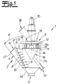
- the sifting device 1 shown serves to sift granular material, e.g. cement, into at least three fractions.
- the device 1 is composed of a static sifter 2 and a dynamic sifter 3, which are combined with one another in a particularly compact manner.
- the static sifter 2 forms a first sifting stage
- the dynamic sifter 3 which is arranged downstream of the static sifter 2 in the direction of the sifting medium flow, forms a second sifting stage.
- the static classifier 2 has a classifier housing 4 with a first material inlet 5, classifying gas inlet 6 and coarse material outlet 7.
- a classifier housing 4 with a first material inlet 5, classifying gas inlet 6 and coarse material outlet 7.
- several impact and guide elements 8, 9 are arranged one below the other in a staircase-like manner.
- these elements are designed as impact plates 8, 9, which also take on the function of guide plates for the static classifier.
- Fig.1 It can be seen that there are two groups of impact plates 8, 9 inclined towards each other, whereby these impact plates 8, 9 are adjustable about pivot axes 10 so that the inclination of the impact plates 8, 9 is adjustable.
- the second classifying stage is formed by the dynamic classifier 3, which has a classifier housing 11.
- This cylindrical classifier housing 11 has an upper cylindrical section 11a and a lower cylindrical section 11b.
- a rotating rod basket 12 is arranged, which is surrounded by a set of guide vanes 13. These are stationary guide vanes that are arranged at a fixed or adjustable angle of attack to the axis of rotation of the rod basket.
- the rod basket 12 rotates about a vertical axis 14.
- a drive 15 is connected to the rod basket 12.
- a discharge cone 16 is connected, which in turn is connected to the medium material outlet 17.
- the fine material outlet 18 is connected to the upper part 11a of the classifier housing 11, through which the gas-fine material mixture is discharged.
- further material inlets 19 are connected to the upper part 11a of the housing.
- the starting material to be sifted is fed to the sifting device 1 via the first material inlet 5.
- the material to be sifted then enters the first sifting stage and subsequently the static sifter 2 via this.
- the sifting gas e.g. air
- This can also be hot drying gases, for example.
- the material to be sifted now falls onto the system of impact and guide plates 8, 9, which in particular leads to the deagglomeration of the flakes and agglomerates created during grinding in a roller press.
- the sifting medium flows through the material and can dry it at the same time.
- the static sifter works as a cross-flow air sifter, so that the coarse material falls through the housing 2 into the lower discharge cone 20 and is discharged from there via the coarse material discharge 7.
- This discharge cone 20 is structurally connected to the lower part 11b of the separator housing 11 of the dynamic separator 3.
- the static classifier and the dynamic classifier are connected to one another in a very compact manner, so that the static classifier 2 merges into the dynamic classifier 3.
- the static classifier is connected with its classifier housing 4 laterally to the classifier housing 11 of the dynamic classifier.
- the classifier housing 4 of the static classifier 2 merges into the lower housing section 11b of the classifier housing 11, so that the housing section 11b of the classifier housing 11 can be functionally assigned to the static classifier on the one hand and the dynamic classifier on the other. It establishes the connection between the static classifier and the dynamic classifier, with the cylindrical lower housing section 11b also fulfilling the function of a cyclone.
- the fraction separated from the static classifier 2 enters the dynamic classifier 3 together with the separating gas, namely into the upper area 11a of the classifier housing 11 and there into the area of the rod basket 12.
- the desired fine separation takes place between this rotating rod basket 12 and the conductor blades 13.
- the "coarser" or medium-sized parts pass through the inner discharge funnel or discharge cone 16 to the discharge pipe and consequently the medium-sized material outlet 17 ("semolina discharge pipe").
- This medium-sized fraction is also referred to as "semolina”.
- the fine material is discharged from the classifier together with the gases through the fine material and gas outlet 18.
- Additional material can be fed directly to the second separation stage via the additional material inlets 19. This can, for example, be material that is fed from an additional crushing device, e.g. a ball mill. This will be discussed in connection with the Fig.6 discussed in more detail.
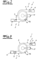
- Fig. 2 and 3 now show that the static classifier 2 according to the invention is connected directly to the second classifier housing 11 of the dynamic classifier 3 with a shaft-like first classifier housing 4 arranged obliquely to the vertical, in the embodiment in tangential or spiral orientation.
- Fig. 2 shows an embodiment with a spiral connection
- Fig.3 shows an embodiment with tangential connection.
- two static classifiers 2 with two classifier housings 4 are connected to the classifier housing 11 of the dynamic classifier 3.
- the dynamic classifier 3 is therefore acted upon in parallel by two static classifiers 2.
- the two static classifiers 2 are positioned offset by 180° in the exemplary embodiment.
- the direction of rotation of the rod basket can correspond to the connection direction of the tangential or spiral connection or can be designed in the opposite direction.
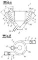
- the Fig. 4 and 5 corresponds essentially to the embodiment according to Fig.1 and 3 . It differs geometrically in particular in the arrangement and design of the discharge funnel 16 of the dynamic classifier, which in the embodiment according to the Fig. 4 and 5 over the entire height of the lower section 11 b of the sifter housing 11 and also over the entire height of the sifter housing 4 of the static sifter 2. Apart from that, the embodiments differ according to Fig. 1 to 3 on the one hand and 4 and 5 on the other hand in their geometric design, especially in the area of the static separator and its guide fittings. The basic structure and functionality are identical.
- the shaft-like first sifter housing which is connected to the second sifter housing in a tangential or spiral orientation, is of particular importance.
- the figures show that this shaft-like first housing 4 or its (lower) shaft wall 21 is oriented at a predetermined angle ⁇ obliquely to the vertical.
- this angle ⁇ is approximately 40° to 60°, e.g. approximately 50°.
- the viewing zone of the static sifter formed between the impact plates 8, 9 arranged one below the other in a step-like manner, is also oriented at a certain angle ⁇ obliquely to the vertical. In the exemplary embodiment, this angle ⁇ is approximately 20° to 40°, e.g. 25°.
- This overall obliquely oriented housing 4 is connected according to the invention in a spiral or tangential manner to the housing of the dynamic sifter.
- FIGS. 1-10 show an embodiment in which the static sifter is connected to the side of the dynamic sifter, but is positioned spatially below the rotating rod basket.
- embodiments can also be implemented optionally in which the static sifter is arranged (at least in some areas) at the same height as the rotating rod basket. The same applies to embodiments with several static sifters.
- the air supply takes place in particular via the illustrated sifting gas inlet 6.
- additional sifting gas inlets can be provided, which are formed in particular by openings arranged in the shaft wall 21. This is not shown in the figures. Such openings can be opened and closed by suitable means, e.g. flaps, slides or the like, whereby variable adjustment and thus air quantity control is possible in particular by adjustable means.
- the arrangement of the impact plates 8, 9 is shown in the figures only as an example. It is indicated that the articulation points of the impact plates 8, 9 do not have to lie on a common straight line, but can be arranged at a distance from each other. This is particularly evident in Fig.4 However, it is also within the scope of the invention that the articulation points of the baffle or guide plates are arranged (for example) on a straight line or are toothed and thus designed to mesh with one another. However, they can also be designed - as shown in the figures - with a distance between the articulation points, whereby this distance is Fig.4 is significantly larger than Fig.1 The vertical distance between the individual plates does not have to be the same, but can vary from plate to plate. The plates can also be set at different angles.
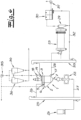
- the multi-stage classifier 1 according to the invention can be particularly preferably integrated into a single-stage or multi-stage grinding plant, as is shown for example in Fig.6 is shown.
- a cement grinding plant is shown as an example.
- the multi-stage classifier 1 can be seen, which is made up of a static classifier 2 and a dynamic classifier 3.
- a first crushing device 22 is shown in the embodiment as a roller press and thus a material bed roller mill 22.
- a second crushing device 23 is shown in the embodiment as a ball mill 23.
- the two-stage grinding system shown works as follows: The starting material to be shredded is fed from one or more bunkers 24, e.g. via the transport devices 25, 26, which open into the sifting device 1 via the material inlet 5. There, the material is sifted into three fractions in the manner already described. The coarse material sifted out from the coarse material outlet 7 is fed again to the roller press 22. From there, it reaches the sifting device 1 again via the transport devices 27 and 25, 26. The medium material sifted out from the second sifting stage, i.e. the middle fraction, is fed to the ball mill 23 via the medium material outlet 17 and the transport device 28.
- the grinding system therefore has the roller press 22 for pre-grinding the material and the ball mill 23 for regrinding the material.
- the ball mill 23 is e.g. B. equipped with a material discharge 29, a dust removal filter 30 and a mill fan 31.
- the material emerging from the ball mill 23 is then fed via the transport devices 29, 32, 33, with which it is brought to the dynamic classifier 3. There it again reaches the second classifying stage via the material inlets 19.
- the finest fraction is removed from the sifting device, namely from the dynamic sifter 3, together with the gases through the fines outlet 18 into the following separation cyclones 34.
- it is separated as a finished product from the gases, which are removed with the fan 35 and partly fed back into the sifting device 1 and partly or completely fed to a dust removal system.
- the two-stage grinding system shown can be modified in an alternative design.
- the roller press 22 can be placed above the sifting device 1, in contrast to the arrangement shown.
- the fresh material to be ground is first fed into the roller press, from which the pre-ground material is fed to the sifting device according to the invention. There, the material is again classified into three fractions in the manner described. This embodiment is not shown.
- a second, separate screening device into the two-stage grinding system, so that the discharge material from the ball mill is then fed not to the first screening device shown in the figures, but to a separate second screening device (not shown).
- a single comminution device e.g. the roller press shown, can be used, so that the additional ball mill is then dispensed with.
- the final grinding then takes place in the roller press, with the screening device according to the invention and the roller press then forming a "simple", "single-stage” circulating grinding system. This is also not shown in the figures.
- the multi-stage screen according to the invention can be used equally for the various types of grinding systems.
Landscapes
- Engineering & Computer Science (AREA)
- Food Science & Technology (AREA)
- Mechanical Engineering (AREA)
- Combined Means For Separation Of Solids (AREA)
- Crushing And Grinding (AREA)
Description
Die Erfindung betrifft eine Vorrichtung zum Sichten von körnigem Gut in zumindest drei Fraktionen, mit zumindest einem eine erste Sichtstufe bildenden statischen Sichter und zumindest einem eine zweite Sichtstufe bildenden dynamischen Sichter,
- wobei der statische Sichter in einem Sichtergehäuse mit zumindest einem ersten Materialeintritt, zumindest einem Sichtgaseinlass und zumindest einem Grobgutaustritt mehrere treppenartig untereinander angeordnete Prall- und Leiteinbauten aufweist,
- wobei der dynamische Sichter als Stabkorbsichter mit rotierendem Stabkorb ausgebildet ist und ein zweites Sichtergehäuse mit zumindest einem Mittelgutaustritt und einem Feingutaustritt aufweist.
- wherein the static classifier has a plurality of impact and guide elements arranged in a staircase-like manner in a classifier housing with at least one first material inlet, at least one classifying gas inlet and at least one coarse material outlet,
- wherein the dynamic sifter is designed as a rod basket sifter with a rotating rod basket and has a second sifter housing with at least one medium material outlet and one fine material outlet.
Bei dem zu sichtenden körnigen Gut kann es sich z. B. um Zement, zementhaltige Stoffe, Zementrohmaterial, Kalkstein oder Schlacke aber auch um Erze oder dergleichen handeln. Für die Zerkleinerung solcher körniger Materialien werden in der Praxis insbesondere Walzenpressen bzw. Gutbettwalzenmühlen eingesetzt. Bei dieser Hochdruckzerkleinerung des körnigen Mahlgutes wird dieses im Spalt zwischen zwei Presswalzen zerdrückt (Gutbettzerkleinerung). Im Zuge der Zerkleinerung kommt es zur Bildung von Agglomeraten, die als Schülpen bezeichnet werden. Derartige Gutbettwalzenmühlen können im geschlossenen Kreislauf mit statischem und/oder dynamischem Sichter betrieben werden. Die Gutbettwalzenmühle wird dann beispielsweise unterhalb eines Sichters positioniert, so dass die aus dem Sichter austretende Grobgutfraktion (erneut) der Walzenmühle zugeführt wird. Das aus der Walzenmühle austretende Material wird wiederum dem Materialeintritt der Sichtvorrichtung zugeführt, die sich als mehrstufige Vorrichtung aus einem statischen Sichter und einem dynamischen Sichter zusammensetzt. In dem statischen Sichter erfolgt über die Prall- und Leiteinbauten eine Desagglomeration der Schülpen, und zugleich wird die grobe Materialfraktion abgeschieden und der Walzenpresse zugeführt. Das "feinere" Gut gelangt mit den Sichtergasen in den dynamischen Sichter, wo es einer Feinsichtung unterzogen wird. Das aus diesem Sichter ausgesichtete Feingut wird zusammen mit dem Sichtgas abgeführt und in den folgenden Zyklonen und/oder Filter als Fertiggut aufgefangen. Die aus dem dynamischen Sichter ausgesichtete mittlere Fraktion kann z. B. ebenfalls erneut der Walzenpresse oder einer weiteren Mahlstufe zugeführt werden. Derartige Maßnahmen sind aus dem Stand der Technik bekannt (vgl. z. B.
Eine gattungsgemäße Sichtvorrichtung der eingangs beschriebenen Art kennt man z. B. aus der
Ebenfalls gattungsgemäß ist die Sichtvorrichtung der
Im Übrigen wurde vorgeschlagen, bei Windsichtern dachförmige Einbauten vorzusehen, die kaskadenförmig derart angeordnet werden, dass die Firstkante jedes Einbaus etwa lotrecht unterhalb der Abwurfkante der dem Windstrom zugekehrten Fläche des darüber hinaus angeordneten Einbaus liegt (vgl.
Aus der
Eine alternative Ausführungsform eines mehrstufigen Sichters mit kompakter Bauform ist aus der
Aus der
Schließlich ist aus der
Im Übrigen beschreibt die
Die bekannten Sichter der beschriebenen Art haben sich in der Praxis grundsätzlich bewährt, sie sind jedoch insbesondere hinsichtlich ihrer Sichteffizienz weiterentwicklungsfähig.The known sifters of the type described have basically proven themselves in practice, but they have potential for further development, particularly with regard to their sifting efficiency.
Der Erfindung liegt daher die Aufgabe zugrunde, eine Vorrichtung zum Sichten von körnigem Gut in zumindest drei Fraktionen der eingangs beschriebenen Art zu schaffen, welche sich nicht nur durch einen besonders kompakten Aufbau, sondern insbesondere auch durch geringe Investitions- und Betriebskosten und höhere Sichteffizienz auszeichnet. Insbesondere soll eine solche Sichtereinrichtung einen wirtschaftlichen Betrieb einer Mahlanlage mit zumindest einer Walzenpresse bei hoher Sichteffizienz ermöglichen.The invention is therefore based on the object of creating a device for classifying granular material into at least three fractions of the type described at the beginning, which is characterized not only by a particularly compact structure, but also in particular by low investment and operating costs and higher classifying efficiency. In particular, such a classifying device should enable economical operation of a grinding plant with at least one roller press with high classifying efficiency.
Zur Lösung dieser Aufgabe stellt die Erfindung eine Vorrichtung zum Sichten von körnigem Gut in zumindest drei Fraktionen zur Verfügung, welche die Merkmale des Anspruchs 1 aufweist.To solve this problem, the invention provides a device for sifting granular material into at least three fractions, which has the features of
Die Erfindung geht dabei zunächst einmal von der grundsätzlich bekannten Erkenntnis aus, dass es vorteilhaft ist, einen statischen Sichter und einen dynamischen Sichter in der Ausführungsform als Stabkorbsichter miteinander zu kombinieren, da über den statischen Sichter eine erste Grobgutfraktion ausgesichtet werden kann, so dass der dynamische Sichter mit den verhältnismäßig empfindlichen rotierenden Komponenten nicht unnötig mit Grobgut belastet wird. Erfindungsgemäß werden der statische und der dynamische Sichter in besonders effizienter und kompakter Bauform zusammengefasst, indem zum einen ein Stabkorb mit vertikaler Drehachse zum Einsatz kommt und zum anderen der statische Sichter direkt seitlich an den dynamischen Sichter angeschlossen ist, wobei der statische Sichter verfahrenstechnisch sowohl die Aufgabe der Schülpendesagglomeration als auch einer ersten Grobabscheidung erfüllt. Statischer Sichter und dynamischer Sichter werden folglich räumlich dicht zusammengebracht, so dass beide Sichter energetisch besonders effizient arbeiten, und der statische Sichter zugleich die Aufgabe der Schülpendesagglomeration erfüllen kann.The invention is based first of all on the fundamentally known finding that it is advantageous to combine a static sifter and a dynamic sifter in the form of a rod basket sifter, since a first coarse material fraction can be sifted out via the static sifter, so that the dynamic sifter with the relatively sensitive rotating components is not unnecessarily burdened with coarse material. According to the invention, the static and dynamic sifters are combined in a particularly efficient and compact design by using a rod basket with a vertical axis of rotation and by connecting the static sifter directly to the side of the dynamic sifter, with the static sifter fulfilling both the task of slug deagglomeration and a first coarse separation in terms of process technology. The static sifter and dynamic sifter are therefore brought spatially close together so that both sifters work particularly efficiently in terms of energy, and the static sifter can simultaneously fulfill the task of slug deagglomeration.
In Kombination mit dem erfindungsgemäßen Anschluss des statischen Sichters an den dynamischen Sichter kommt dem Einsatz des um eine vertikale Achse rotierenden Stabkorbsichters besondere Bedeutung zu. Denn diese Ausgestaltung mit "vertikalem" Stabkorbsichter zeichnet sich durch eine gleichmäßige Anströmung des Stabkorbes bzw. Rotors und damit durch verbesserte Sichteffizienz aus. Die beim Stand der Technik mit "horizontal" angeordneten Stabkorbachsen auftretenden Probleme werden im Rahmen der Erfindung vermieden, so dass insgesamt eine verbesserte Sichteffizienz realisiert wird.In combination with the inventive connection of the static sifter to the dynamic sifter, the use of the rod basket sifter rotating around a vertical axis is of particular importance. This design with a "vertical" rod basket sifter is characterized by a uniform flow of air to the rod basket or rotor and thus by improved sifting efficiency. The problems that occur in the prior art with "horizontally" arranged rod basket axes are avoided within the scope of the invention, so that an overall improved sifting efficiency is achieved.
Erfindungsgemäß mündet das Sichtergehäuse des statischen Sichters in tangentialer oder spiralförmiger Orientierung in das Sichtergehäuse des dynamischen Sichters. Jedenfalls ist das Sichtergehäuse des statischen Sichters stets kompakt seitlich an das Sichtergehäuse des dynamischen Sichters angeschlossen, so dass das statische Sichtergehäuse in das dynamische Sichtergehäuse übergeht. Der erfindungsgemäße Sichter weist folglich Gehäusebereiche auf, die als Übergang zwischen statischem Sichter und dynamischem Sichter sowohl dem statischen Sichter als auch dem dynamischen Sichter zugeordnet werden können. So ist weiterhin vorgesehen, dass das Sichtergehäuse des dynamischen Sichters einen oberen Gehäuseabschnitt aufweist, in dem der rotierende Stabkorb angeordnet ist, und einen unteren Gehäuseabschnitt aufweist, in dem ein Ausfalltrichter für das Mittelgut angeordnet ist, wobei der statische Sichter mit seinem Gehäuse an den unteren Gehäuseabschnitt des dynamischen Sichters angeschlossen ist und in diesen unteren Gehäuseabschnitt übergeht. Dieser untere Gehäuseabschnitt des dynamischen Sichters bildet folglich den Übergangsbereich zwischen statischem Sichter und dynamischen Sichter. Das Gehäuse des dynamischen Sichters ist zylindrisch ausgebildet, so dass der obere Gehäuseabschnitt und der untere Gehäuseabschnitt zylindrisch ausgebildet sind. Dem un-teren Gehäuseabschnitt des dynamischen Sichters kommt dann auch die Funktion eines Zyklons zu, der sowohl die Funktion des statischen Sichters als auch die Funktion des dynamischen Sichters beeinflussen kann. So kann dieser von dem unteren Gehäuseabschnitt gebildete Zyklon die Wirkung der statischen Sichtstufe beeinflussen. Gleichzeitig kann man diesen Zyklon aber auch als Teil des dynamischen Sichters betrachten, da er einen Anströmkanal für die senkrechte Beaufschlagung des Stabkorbes bildet und da innerhalb dieses Gehäuseabschnittes bzw. Zyklons auch der Ausfalltrichter des dynamischen Sichters angeordnet sein kann. Auch dadurch wird deutlich, dass erfindungsgemäß der statische Sichter und der dynamische Sichter räumlich und auch funktionell eng miteinander verbunden werden.According to the invention, the sifter housing of the static sifter opens into the sifter housing of the dynamic sifter in a tangential or spiral orientation. In any case, the sifter housing of the static sifter is always compactly connected laterally to the sifter housing of the dynamic sifter, so that the static sifter housing merges into the dynamic sifter housing. The sifter according to the invention therefore has housing areas which can be assigned to both the static sifter and the dynamic sifter as a transition between the static sifter and the dynamic sifter. It is further provided that the sifter housing of the dynamic sifter has an upper housing section in which the rotating rod basket is arranged, and a lower housing section in which a discharge funnel for the middle material is arranged, the static sifter being connected with its housing to the lower housing section of the dynamic sifter and merging into this lower housing section. This lower housing section of the dynamic sifter therefore forms the transition area between the static sifter and the dynamic sifter. The housing of the dynamic classifier is cylindrical, so that the upper housing section and the lower housing section are cylindrical. The lower housing section of the dynamic classifier then also functions as a cyclone, which can influence both the function of the static classifier and the function of the dynamic classifier. This cyclone formed by the lower housing section can influence the effect of the static classifying stage. At the same time, however, this cyclone can also be viewed as part of the dynamic classifier, since it forms an inflow channel for the vertical impact on the rod basket and since the discharge funnel of the dynamic classifier can also be arranged within this housing section or cyclone. This also makes it clear that, according to the invention, the static classifier and the dynamic classifier are closely connected spatially and functionally.
Wie beschrieben ist der statische Sichter bevorzugt an den unteren Gehäuseabschnitt des dynamischen Sichters angeschlossen. Dann ist der statische Sichter (in einer Seitenansicht) in der Regel unterhalb des Stabkorbes positioniert. Alternativ liegt es jedoch im Rahmen der Erfindung, den statischen Sichter bzw. die statischen Sichter auf gleicher Höhe oder zumindest bereichsweise auf gleicher Höhe mit dem rotierenden Stabkorb anzuordnen.As described, the static classifier is preferably attached to the lower housing section of the dynamic The static sifter is then usually positioned below the rod basket (in a side view). Alternatively, however, it is within the scope of the invention to arrange the static sifter or static sifters at the same height or at least in some areas at the same height as the rotating rod basket.
Innerhalb des statischen Sichters kommt es nicht nur zu einer ersten Trennung von Grobgut und Mittelgut, sondern es kann auch eine Schülpendesagglomeration erfolgen. Die Schülpendesagglomeration wird mit Hilfe der in den statischen Sichter integrierten Prall- und Leiteinbauten realisiert. Die Prall- und Leiteinbauten können in an sich bekannter Weise von gegeneinander geneigten Prallplatten bzw. Leitblechen gebildet werden. In bevorzugter Ausführungsform sind diese Platten bzw. Bleche in ihrer Neigung einstellbar, z. B. um eine horizontale Achse verschwenk- bzw. drehbar. Da die Funktionsweise des statischen Sichters während des Betriebes - im Gegensatz zu einem dynamischen Sichter - nur begrenzt beeinflussbar ist, ist eine solche Einstellmöglichkeit zweckmäßig. Es können die gewünschten Gegebenheiten des statischen Sichters eingestellt werden, so dass insbesondere die Strömungsverhältnisse optimierbar sind. Alternativ können die Prall- und Leiteinbauten auch von dachartigen Einbauten gebildet werden, wie sie z. B. aus der
Während das (zweite) Sichtergehäuse des dynamischen Sichters in der Regel zylindrisch oder zumindest bereichsweise zylindrisch ausgebildet ist, weist der statische Sichter ein schachtartiges bzw. kastenartiges Gehäuse auf, das bevorzugt schräg zur Vertikalen ausgerichtet ist, so dass auch die im Innern angeordneten Prall- und Leiteinbauten entlang einer Schrägen angeordnet sind. Das schachtartige Gehäuse weist zum einen den Materialeintritt oder die Materialeintritte für das zu sichtende Gut und zum anderen zumindest einen Sichtgaseinlass auf, über welchen z. B. Luft zugeführt wird. Dazu kann das schachtartige Gehäuse eine (untere) Schachtwand aufweisen, welche unter einem vorgegebenen Winkel α zwischen 10° und 80°, z. B. 40° bis 60° orientiert ist. Das Gehäuse kann folglich (in der Seitenansicht) insgesamt schräg zur Vertikalen angeordnet sein. Gleiches gilt für die innerhalb des Gehäuses treppenartig untereinander angeordneten Prall- und Leiteinbauten. Zwischen diesen wird die Sichtzone der ersten Sichtstufe gebildet, welche unter einem vorgegebenen Winkel β zwischen 20° und 70°, z. B. 20° bis 40° bezogen auf die Vertikale orientiert ist. Die Erfindung umfasst aber auch ein schachtartiges Gehäuse, welches nicht schräg zur Vertikalen ausgerichtet ist, sondern parallel zur Vertikalen.While the (second) sifter housing of the dynamic sifter is usually cylindrical or at least partially cylindrical, the static sifter has a shaft-like or box-like housing that is preferably aligned at an angle to the vertical, so that the impact and guide fittings arranged inside are also arranged along a slope. The shaft-like housing has the material inlet or inlets for the material to be sifted and at least one sifting gas inlet, via which air is supplied, for example. For this purpose, the shaft-like housing can have a (lower) shaft wall that is oriented at a predetermined angle α between 10° and 80°, e.g. 40° to 60°. The housing can therefore be arranged (in side view) overall at an angle to the vertical. The same applies to the impact and guide fittings arranged one below the other in a staircase-like manner within the housing. Between these, the viewing zone of the first viewing stage is formed, which is oriented at a predetermined angle β between 20° and 70°, e.g. 20° to 40° relative to the vertical. However, the invention also includes a shaft-like housing which is not oriented at an angle to the vertical, but parallel to the vertical.
Der Sichtgaseintritt kann z. B. von zumindest einer schräg oberhalb der Einbauten angeordneten Eintrittsöffnung gebildet werden. Alternativ oder ergänzend besteht die Möglichkeit, dass der Sichtgaseintritt von einer oder mehreren in der Schachtwand angeordneten Öffnungen gebildet wird. Diese Öffnungen können z. B. durch Klappen verschließbar sein, so dass durch Öffnen und Schließen die Sichtgaszuführung variiert werden kann. Es liegt folglich im Rahmen der Erfindung, dass entweder eine (obere) Eintrittsöffnung der beschriebenen Art vorgesehen ist oder dass Öffnungen in der Schachtwand vorgesehen sind. Bevorzugt wird jedoch eine Kombination dieser Maßnahmen realisiert, so dass dann sowohl zumindest eine schräg oberhalb der Einbauten angeordnete Eintrittsöffnung als auch eine oder mehrere in der Schachtwand angeordnete Öffnungen vorgesehen sind, wobei diese Öffnungen optional z. B. durch Klappen verschließbar sind. Es besteht dann die Möglichkeit mit "variabler" Luftzufuhr und folglich einer Luftmengenregelung zu arbeiten. Dabei ist es zweckmäßig, wenn die einzelnen Klappen einzeln, in Gruppen und/oder gemeinsam zu öffnen und zu schließen sind, wobei besonders bevorzugt durch die Einstellung der Öffnungen eine variable und gezielte Anpassung möglich wird. Klappen meint dabei im Rahmen der Erfindung allgemein Mittel zum Öffnen und Schließen der Öffnungen und insbesondere zum Einstellen der Luftdurchtrittsmenge. Durch geeignete Luftmengenregelung besteht die Möglichkeit, die Sichteffizienz weiter zu steigern.The sifting gas inlet can be formed, for example, by at least one inlet opening arranged diagonally above the internals. Alternatively or additionally, it is possible for the sifting gas inlet to be formed by one or more openings arranged in the shaft wall. These openings can be closed, for example, by flaps, so that the sifting gas supply can be varied by opening and closing. It is therefore within the scope of the invention that either an (upper) inlet opening of the type described is provided or that openings are provided in the shaft wall. Preferably, however, a combination of these measures is implemented, so that at least one inlet opening arranged diagonally above the internals and one or more openings arranged in the shaft wall are provided, whereby these openings can optionally be closed, for example, by flaps. It is then possible to work with "variable" air supply and consequently air volume control. It is expedient if the individual flaps can be opened and closed individually, in groups and/or together, whereby variable and targeted adjustment is particularly preferably possible by adjusting the openings. In the context of the invention, flaps generally mean means for opening and closing the openings and in particular for adjusting the amount of air passing through. By regulating the air volume appropriately, it is possible to further increase the visibility efficiency.
Weiter besteht optional oder ergänzend die Möglichkeit, dass der Sichtgaseintritt von einem schachtwandfreien Bereich des Sichtergehäuses gebildet wird. Bei dieser Ausführungsform kann auf die Schachtwand verzichtet werden, so dass dann mit offener Anströmung gearbeitet wird.There is also the option, or additional option, for the classifying gas inlet to be formed by an area of the classifier housing that is free of shaft walls. In this embodiment, the shaft wall is not required, so that the system can then operate with an open flow.
Von besonderer Bedeutung ist im Rahmen der Erfindung die Kombination des seitlich, z. B. tangential- oder spiralförmig angeschlossenen ersten Sichtergehäuses mit dem in vertikaler Orientierung angeordneten Stabkorb. Die Drehrichtung des Stabkorbes kann mit oder entgegen der tangentialen bzw. spiralartigen Anschlussrichtung des statischen Sichtergehäuses orientiert sein.Of particular importance within the scope of the invention is the combination of the first separator housing, which is connected laterally, e.g. tangentially or spirally, with the rod basket arranged in a vertical orientation. The direction of rotation of the rod basket can be oriented with or against the tangential or spiral-like connection direction of the static separator housing.
Der dynamische Sichter ist besonders bevorzugt im oberen Teil, z. B. im oberen Gehäuseabschnitt mit einem oder mehreren weiteren Materialeintritten versehen. Dieses ist insbesondere dann zweckmäßig, wenn der Sichter in eine mehrstufige Mahlanlage integriert wird, weil dann über diesen (zweiten) Materialeintritt das gemahlene Gut einer zweiten Stufe zur Sichtung zugeführt werden kann. Dabei kann es sich z. B. um das Austragsgut einer zweiten Zerkleinerungsvorrichtung, z. B. einer Kugelmühle, handeln. Die Einbindung der Sichtereinrichtung in eine ein- oder mehrstufige Mahlanlage wird im Folgenden noch näher erläutert.The dynamic classifier is particularly preferably provided with one or more additional material inlets in the upper part, e.g. in the upper housing section. This is particularly useful if the classifier is integrated into a multi-stage grinding system, because the ground material can then be fed to a second stage for classifying via this (second) material inlet. This can, for example, be the discharge material from a second comminution device, e.g. a ball mill. The integration of the classifier device into a single- or multi-stage grinding system is explained in more detail below.
Es liegt grundsätzlich im Rahmen der Erfindung, dass ein einzelner statischer Sichter in der erfindungsgemäßen, z. B. tangentialen bzw. spiralförmigen, Art an den dynamischen Sichter angeschlossen ist. Bevorzugt sind jedoch, insbesondere bei großen Einheiten, zwei oder auch mehrere statische Sichter mit jeweils einem Sichtergehäuse an den dynamischen Sichter angeschlossen. Die Vorsichtung zum Aussichten einer Grobgutfraktion und zum Desagglomerieren der Schülpe kann folglich parallel in mehreren Vorsichtsstufen durchgeführt werden, wobei dann die einzelnen Vorsichtstufen parallel ein- und denselben dynamischen Sichter beaufschlagen. Der Anschluss der mehreren statischen Sichter erfolgt dabei (in der Draufsicht) vorzugsweise symmetrisch. So liegt es im Rahmen der Erfindung, dass die mehreren statischen Sichter über den Umfang "symmetrisch" und folglich äquidistant angeordnet werden. Der Versatz beträgt dabei bezogen auf den Umfang 360°/n, wobei mit "n" die Anzahl der statischen Sichter gemeint ist. Werden folglich zwei statische Sichter verwendet, so sind diese in der Draufsicht bevorzugt um einen Winkel von 180° versetzt an den dynamischen Sichter angeschlossen. Werden drei statische Sichter verwendet, so sind diese bevorzugt um einen Winkel von etwa 120° versetzt angeordnet, und werden vier statische Sichter verwendet, so sind diese bevorzugt um einen Winkel von 90° versetzt zueinander angeordnet, usw..It is fundamentally within the scope of the invention that a single static separator in the inventive, e.g. tangential or spiral, type is connected to the dynamic separator. Preferably However, especially in large units, two or more static sifters, each with a sifter housing, are connected to the dynamic sifter. The sifting for sifting a coarse material fraction and for deagglomerating the slugs can therefore be carried out in parallel in several sifting stages, with the individual sifting stages then acting in parallel on one and the same dynamic sifter. The connection of the several static sifters is preferably symmetrical (in plan view). It is therefore within the scope of the invention that the several static sifters are arranged "symmetrically" and thus equidistantly around the circumference. The offset is 360°/n in relation to the circumference, where "n" means the number of static sifters. If two static sifters are used, they are preferably connected to the dynamic sifter offset by an angle of 180° in plan view. If three static classifiers are used, they are preferably arranged offset by an angle of approximately 120°, and if four static classifiers are used, they are preferably arranged offset by an angle of 90° from each other, etc.
Zusätzlich zu den im statischen Sichter ohnehin vorgesehenen Prall- und Leiteinbauten kann es zweckmäßig sein, auch im Bereich des dynamischen Sichters Pralleinbauten vorzusehen, z. B. innerhalb des Sichtergehäuses des dynamischen Sichters, vorzugsweise in dessen unterem Gehäuseabschnitt, welcher aus den erläuterten Gründen die Funktion eines Zyklons übernehmen kann. An die Gehäusewand dieses Zyklons können innenseitig Pralleinbauten angeschlossen werden, welche als "Stolperkanten" oder "Abschälkanten" funktionieren können. Sie sollen der Zyklonwirkung dieses Teils des Sichters entgegenwirken und diese Zyklonwirkung folglich reduzieren. Denn mit Hilfe dieser wandseitig angeordneten Einbauten kann das sich im Wandbereich sammelnde Material wieder in Richtung Zentrum bzw. Achse gebracht werden, so dass die Sichtfunktion optimiert wird.In addition to the impact and guide fittings already provided in the static classifier, it can be useful to also provide impact fittings in the area of the dynamic classifier, e.g. inside the classifier housing of the dynamic classifier, preferably in its lower housing section, which can take on the function of a cyclone for the reasons explained. Impact fittings can be connected to the inside of the housing wall of this cyclone, which can function as "tripping edges" or "peeling edges". They are intended to counteract the cyclone effect of this part of the classifier and consequently reduce this cyclone effect. With the help of these fittings arranged on the wall, the material collecting in the wall area can be brought back towards the center or axis, so that the screening function is optimized.
Nach einem weiteren Vorschlag ist optional vorgesehen, dass das Sichtergehäuse des dynamischen Sichters mit einer oder mehreren zusätzlichen Luftzuführungen versehen ist, die die Funktion eines Luftbypasses übernehmen. Es erfolgt dann nicht nur die Luftzuführung über den Lufteintritt des statischen Sichters, sondern über den dynamischen Sichter kann zusätzliche Luft zugeführt werden. Dieses führt dann dazu, dass die Luftzufuhr im Bereich des statischen Sichters verringert wird, so dass auf diese Weise eine optimierte Anpassung der Luftführung realisierbar ist. Diese zusätzliche Luftzuführung kann z. B. im oberen Gehäuseabschnitt des Sichtergehäuses des dynamischen Sichters realisiert werden.According to another proposal, it is optionally provided that the sifter housing of the dynamic sifter is provided with one or more additional air inlets that take on the function of an air bypass. Not only is the air supplied via the air inlet of the static sifter, but additional air can also be supplied via the dynamic sifter. This then leads to the air supply in the area of the static sifter being reduced, so that an optimized adjustment of the air flow can be achieved in this way. This additional air supply can be implemented, for example, in the upper housing section of the sifter housing of the dynamic sifter.
Schließlich liegt es im Rahmen der Erfindung, optional im Bereich des statischen Sichters zusätzliche Luftverteileinrichtungen, z. B. Lochbleche o. dgl., vorzusehen. Diese können in das Sichtergehäuse des statischen Sichters in Strömungsrichtung vor den Prall- und Leiteinbauten angeordnet werden. Sie führen zu einer besseren Luftverteilung über die gesamte Höhe des statischen Sichters.Finally, it is within the scope of the invention to optionally provide additional air distribution devices, e.g. perforated plates or the like, in the area of the static classifier. These can be arranged in the classifier housing of the static classifier in the direction of flow in front of the impact and guide fittings. They lead to better air distribution over the entire height of the static classifier.
Die erfindungsgemäße Sichtereinrichtung lässt sich für das Sichten von körnigen Materialien unterschiedlichster Art einsetzen, insbesondere zum Sichten von Zement, Zementrohstoffen, Kalkstein und ähnlichen Stoffen. Alternativ umfasst die Erfindung aber auch das Sichten von Erzen oder dergleichen. Die natürlichen Vorräte solcher Rohstoffe sind zum Teil weitgehend ausgebeutet, so dass sich die Gewinnung in schwer zugängliche Regionen ohne ausreichende Wasservorräte verschiebt. Dort kann der erfindungsgemäße Sichter besonders effizient eingesetzt werden.The sifting device according to the invention can be used for sifting a wide variety of granular materials, in particular for sifting cement, cement raw materials, limestone and similar materials. Alternatively, the invention also covers the sifting of ores or the like. The natural reserves of such raw materials have been largely exhausted, so that extraction is shifting to regions that are difficult to access and do not have sufficient water supplies. The sifter according to the invention can be used particularly efficiently there.
Gegenstand der Erfindung ist auch eine einstufige (Kreislaufmahlanlage) oder mehrstufige Mahlanlage für die Zerkleinerung von körnigem Gut mit
- zumindest einer ersten Zerkleinerungsvorrichtung und
- zumindest einer Sichtereinrichtung der beschriebenen Art,
- at least one first crushing device and
- at least one screening device of the type described,
Alternativ kann jedoch auch eine mehrstufige, z. B. zweistufige Mahlanlage realisiert werden, bei welcher zusätzlich zu dem erfindungsgemäßen Sichter ein weiterer, separater Sichter vorgesehen ist. Die mittlere Fraktion des beschriebenen erfindungsgemäßen ersten Sichters wird wiederum einer zweiten Zerkleinerungsvorrichtung, z. B. einer Kugelmühle zugeführt. Das Austragsmaterial dieser Kugelmühle wird dann jedoch nicht - wie zuvor beschrieben - wiederum dem ersten Sichter, sondern dem zweiten, separaten Sichter zugeführt, wobei das aus diesem zweiten Sichter austretende Grobgut nochmals der Kugelmühle zugeführt wird, während das aus dem zweiten Sichter austretende Feingut wiederum als Produkt abgeführt werden kann.Alternatively, however, a multi-stage, e.g. two-stage grinding system can be implemented, in which a further, separate sifter is provided in addition to the sifter according to the invention. The middle fraction of the first sifter according to the invention described is in turn fed to a second comminution device, e.g. a ball mill. The discharge material from this ball mill is then not - as previously described - fed to the first sifter, but to the second, separate sifter, whereby the coarse material emerging from this second sifter is fed to the ball mill again, while the fine material emerging from the second sifter can in turn be discharged as product.
Schließlich werden erfindungsgemäß aber auch einstufige Mahlanlagen umfasst, bei denen sowohl das aus der erfindungsgemäßen Sichteinrichtung austretende Grobgut als auch das Mittelgut einer ersten (einzigen) Zerkleinerungsvorrichtung, z. B. Walzenpresse, zugeführt wird und wobei das aus dieser Zerkleinerungsvorrichtung austretende Material wiederum über den Materialeintritt in die erfindungsgemäße Sichtvorrichtung eintritt. Damit wird eine einstufige Kreislaufmahlanlage realisiert.Finally, the invention also includes single-stage grinding systems in which both the coarse material emerging from the screening device according to the invention and the medium material are fed to a first (single) comminution device, e.g. a roller press, and the material emerging from this comminution device in turn enters the screening device according to the invention via the material inlet. This creates a single-stage circulating grinding system.
Es liegt dabei im Rahmen der Erfindung, dass die erste Zerkleinerungsvorrichtung, z. B. Walzenpresse, oberhalb der Sichtereinrichtung angeordnet ist. Besonders bevorzugt ist die Walzenpresse jedoch unterhalb der Sichtereinrichtung positioniert. Im Folgenden wird die Erfindung anhand einer lediglich ein Ausführungsbeispiel darstellenden Zeichnung näher erläutert. Es zeigen:
- Fig. 1
- einen teilweisen Vertikalschnitt durch eine erfindungsgemäße Sichtereinrichtung in vereinfachter Darstellung,
- Fig. 2
- eine Draufsicht auf den unteren Teil des Gegenstandes nach
Fig. 1 in einer ersten Ausführungsform, - Fig. 3
- eine Draufsicht auf den unteren Teil des Gegenstandes nach
Fig. 1 in einer zweiten Ausführungsform, - Fig. 4
- eine abgewandelte Ausführungsform des Gegenstandes nach
Fig. 1 (Ausschnitt im Bereich des Unterteils), - Fig. 5
- eine Draufsicht auf den unteren Teil des Gegenstandes nach
Fig. 4 und - Fig. 6
- schematisch eine zweistufige Mahlanlage mit einer erfindungsgemäßen Sichtereinrichtung.
- Fig.1
- a partial vertical section through a sifting device according to the invention in a simplified representation,
- Fig. 2
- a plan view of the lower part of the object after
Fig.1 in a first embodiment, - Fig.3
- a plan view of the lower part of the object after
Fig.1 in a second embodiment, - Fig.4
- a modified embodiment of the article according to
Fig.1 (cutout in the lower part area), - Fig.5
- a plan view of the lower part of the object after
Fig.4 and - Fig.6
- schematically shows a two-stage grinding plant with a classifying device according to the invention.
Die in den
Der statische Sichter 2 weist ein Sichtergehäuse 4 mit erstem Materialeintritt 5, Sichtgaseinlass 6 und Grobgutaustritt 7 auf. Innerhalb des Sichtergehäuses 4 sind mehrere, treppenartig untereinander angeordnete Prall- und Leiteinbauten 8, 9 angeordnet. Im Ausführungsbeispiel sind diese Einbauten als Prallplatten 8, 9 ausgebildet, die zugleich die Funktion von Leitblechen für den statischen Sichter übernehmen. In
Die zweite Sichtstufe wird von dem dynamischen Sichter 3 gebildet, der ein Sichtergehäuse 11 aufweist. Dieses zylindrische Sichtergehäuse 11 weist einen oberen zylindrischen Abschnitt 11a und einen un-teren zylindrischen Abschnitt 11 b auf. Im oberen Teil 11 a dieses Sichtergehäuses 11 ist ein rotierender Stabkorb 12 angeordnet, den ein Satz von Leitschaufeln 13 umgibt. Dabei handelt es sich um stationäre Leitschaufeln, die unter einem festen oder auch einstellbaren Anstellwinkel zur Rotationsachse des Stabkorbes angeordnet sind. Der Stabkorb 12 rotiert um eine vertikale Achse 14. Dazu ist an dem Stabkorb 12 ein Antrieb 15 angeschlossen. Unterhalb des Stabkorbes 12 ist innerhalb des zweiten Sichtergehäuses 11 ein Ausfallkegel 16 angeschlossen, der wiederum an den Mittelgutaustritt 17 angeschlossen ist. An das Oberteil 11a des Sichtergehäuses 11 ist der Feingutaustritt 18 angeschlossen, wobei über diesen das Gas-Feingut-Gemisch abgeführt wird. Ferner sind an das Gehäuseoberteil 11a weitere Materialeintritte 19 angeschlossen.The second classifying stage is formed by the
Das zu sichtende Ausgangsmaterial wird der Sichtvorrichtung 1 über den ersten Materialeintritt 5 zugeführt. Über diesen gelangt das zu sichtende Gut folglich in die erste Sichtstufe und folglich in den statischen Sichter 2. Durch den Gaseintritt 3 wird das Sichtgas, z. B. Luft zugeführt. Dabei kann es sich z. B. auch heiße Trocknungsgase handeln. Das zu sichtende Material fällt nun auf das System von Prall- und Leitplatten 8, 9, wobei es insbesondere zur Desagglomeration der beim Mahlen in einer Walzenpresse entstandenen Schülpen und Agglomerate kommt. Dabei wird das Material von dem Sichtmedium bei möglicher, gleichzeitiger Trocknung durchströmt. Der statische Sichter arbeitet als Querstrom-Windsichter, so dass das Grobgut durch das Gehäuse 2 in den unteren Ausfallkegel 20 fällt und von dort über den Grobgutaustrag 7 ausgetragen wird. Dieser Ausfallkegel 20 ist baulich an den unteren Teils 11b des Sichtergehäuses 11 des dynamischen Sichters 3 angeschlossen.The starting material to be sifted is fed to the
Der statische Sichter und der dynamische Sichter sind in sehr kompakter Weise miteinander verbunden, so dass der statische Sichter 2 in den dynamischen Sichter 3 übergeht. Denn der statische Sichter ist mit seinem Sichtergehäuse 4 seitlich an das Sichtergehäuse 11 des dynamischen Sichters angeschlossen. Im Ausführungsbeispiel ist erkennbar, dass das Sichtergehäuse 4 des statischen Sichters 2 in den unteren Gehäuseabschnitt 11 b des Sichtergehäuses 11 übergeht, so dass der Gehäuseabschnitt 11 b des Sichtergehäuses 11 funktionell bereichsweise einerseits dem statischen Sichter und andererseits dem dynamischen Sichter zugeordnet werden kann. Er stellt die Verbindung zwischen dem statischen Sichter und dem dynamischen Sichter her, wobei der zylindrische untere Gehäuseabschnitt 11b auch die Funktion eines Zyklons erfüllt.The static classifier and the dynamic classifier are connected to one another in a very compact manner, so that the
Jedenfalls tritt die aus dem statischen Sichter 2 ausgesichtete Fraktion gemeinsam mit dem Sichtgas in den dynamischen Sichter 3, nämlich in den oberen Bereich 11a des Sichtergehäuses 11 und dort in den Bereich des Stabkorbes 12. Zwischen diesem rotierenden Stabkorb 12 und den Leiterschaufeln 13 kommt es zu der gewünschten Feinsichtung. Die "gröberen" bzw. mittleren Anteile gelangen über den inneren Ausfalltrichter bzw. Ausfallkegel 16 zu dem Ausfallrohr und folglich Mittelgutaustritt 17 ("Grießausfallrohr"). Diese mittlere Fraktion wird auch als "Grieße" bezeichnet. Das Feingut wird zusammen mit den Gasen durch den Feingut- und Gasaustritt 18 aus dem Sichter ausgetragen. Über die zusätzlichen Materialeintritte 19 lässt sich weiteres Material unmittelbar der zweiten Sichtstufe zuführen. Dabei kann es sich z. B. um Material handeln, welches aus einer zusätzlichen Zerkleinerungsvorrichtung, z. B. einer Kugelmühle zugeführt wird. Darauf wird im Zusammenhang mit der
Die
Dabei ist in den beiden Ausführungsbeispielen erkennbar, dass jeweils zwei statische Sichter 2 mit zwei Sichtergehäusen 4 an das Sichtergehäuse 11 des dynamischen Sichters 3 angeschlossen sind. Der dynamische Sichter 3 wird folglich parallel von zwei statischen Sichtern 2 beaufschlagt. Dazu sind die beiden statischen Sichter 2 im Ausführungsbeispiel um 180° versetzt positioniert. Die Drehrichtung des Stabkorbes, kann der Anschlussrichtung des tangentialen bzw. spiralförmigen Anschlusses entsprechen oder auch dieser entgegen ausgeführt sein.It can be seen in the two exemplary embodiments that two
Die in den
Dem schachtartigen ersten Sichtergehäuse, welches in tangentialer oder spiralförmiger Orientierung an das zweite Sichtergehäuse angeschlossen ist, kommt besondere Bedeutung zu. Die Figuren zeigen dabei, dass dieses schachtartige erste Gehäuse 4 bzw. dessen (untere) Schachtwand 21 unter einem vorgege benen Winkel α schräg gegenüber der Vertikalen orientiert ist. Im Ausführungsbeispiel beträgt dieser Winkel α etwa 40° bis 60°, z. B. ca. 50°. Es ist im Übrigen erkennbar, dass auch die zwischen den treppenartig untereinander angeordneten Prallplatten 8, 9 gebildete Sichtzone des statischen Sichters unter einem bestimmten Winkel β schräg gegenüber der Vertikalen orientiert ist. Im Ausführungsbeispiel beträgt dieser Winkel β etwa 20° bis 40°, z. B. 25°. Dieses insgesamt schräg orientierte Gehäuse 4 ist erfindungsgemäß spiralförmig bzw. tangential an das Gehäuse des dynamischen Sichters angeschlossen.The shaft-like first sifter housing, which is connected to the second sifter housing in a tangential or spiral orientation, is of particular importance. The figures show that this shaft-like
Die Figuren zeigen dabei eine Ausführungsform, bei welcher der statische Sichter zwar seitlich an den dynamischen Sichter angeschlossen ist, jedoch räumlich unterhalb des rotierenden Stabkorbes positioniert ist. Optional können jedoch auch Ausführungsformen realisiert werden, bei denen der statische Sichter (zumindest bereichsweise) auf gleicher Höhe mit dem rotierenden Stabkorb angeordnet ist. Gleiches gilt für Ausführungsformen mit mehreren statischen Sichtern.The figures show an embodiment in which the static sifter is connected to the side of the dynamic sifter, but is positioned spatially below the rotating rod basket. However, embodiments can also be implemented optionally in which the static sifter is arranged (at least in some areas) at the same height as the rotating rod basket. The same applies to embodiments with several static sifters.
Im Übrigen erfolgt bei den dargestellten Ausführungsformen die Luftzuführung insbesondere über den dargestellten Sichtgaseintritt 6. Alternativ oder ergänzend können zusätzliche Sichtgaseintritte vorgesehen sein, die insbesondere von in der Schachtwand 21 angeordneten Öffnungen gebildet werden. Dieses ist in den Figuren nicht dargestellt. Solche Öffnungen können durch geeignete Mittel, z. B. Klappen, Schieber oder dergleichen zu öffnen und zu schließen sein, wobei insbesondere durch einstellbare Mittel eine variable Anpassung und damit Luftmengenregelung möglich wird.Furthermore, in the embodiments shown, the air supply takes place in particular via the illustrated sifting
Die Anordnung der Prallplatten 8, 9 ist in den Figuren lediglich beispielhaft dargestellt. Es ist angedeutet, dass die Anlenkpunkte der Prallplatten 8, 9 nicht auf einer gemeinsamen Geraden liegen müssen, sondern beabstandet voneinander angeordnet seien können. Dieser ist insbesondere in
Der erfindungsgemäße, mehrstufige Sichter 1 lässt sich besonders bevorzugt in eine einstufige oder mehrstufige Mahlanlage integrieren, wie sie beispielhaft in
Die dargestellte zweistufige Mahlanlage arbeitet wie folgt:
Das zu zerkleinernde Ausgangsmaterial wird aus einem oder mehreren Bunkern 24 zugeführt, z. B. über die Transporteinrichtungen 25, 26, welche über den Materialeintritt 5 in die Sichtvorrichtung 1 münden. Dort erfolgt in der bereits beschriebenen Weise die Sichtung des Materials in drei Fraktionen. Das aus dem Grobgutaustritt 7 ausgesichtete Grobgut wird erneut der Walzenpresse 22 zugeführt. Von dort gelangt es über die Transporteinrichtungen 27 und 25, 26 erneut in die Sichtvorrichtung 1. Das aus der zweiten Sichtstufe ausgesichtete Mittelgut, das heißt die mittlere Fraktion, wird über den Mittelgutaustritt 17 und die Transporteinrichtung 28 der Kugelmühle 23 zugeführt. Die Mahlanlage weist folglich die Walzenpresse 22 für das Vormahlen des Materials und die Kugelmühle 23 für das Nachmahlen des Materials auf. Die Kugelmühle 23 ist z. B. mit einem Materialabzug 29, einem Entstaubungsfilter 30 und einem Mühlenventilator 31 ausgestattet. Das aus der Kugelmühle 23 austretende Material wird folglich über die Transporteinrichtungen 29, 32, 33 zugeführt, mit welchen es zum dynamischen Sichter 3 gebracht wird. Dort gelangt es über die Materialeintritte 19 wiederum in die zweite Sichtstufe.The two-stage grinding system shown works as follows:
The starting material to be shredded is fed from one or
Die feinste Fraktion wird aus der Sichtvorrichtung, nämlich aus dem dynamischen Sichter 3 zusammen mit den Gasen durch den Feingutaustritt 18 in die folgenden Abscheidezyklone 34 abgezogen. Hier wird sie als Fertigprodukt von den Gasen getrennt, die mit dem Ventilator 35 abgezogen und teilweise zurück in die Sichtereinrichtung 1 und teilweise oder auch vollständig einer Entstaubung zugeführt werden.The finest fraction is removed from the sifting device, namely from the
Die dargestellte zweistufige Mahlanlage kann in alternativer Ausgestaltung modifiziert werden. So kann z. B. die Walzenpresse 22 im Gegensatz zu der dargestellten Anordnung oberhalb der Sichtereinrichtung 1 platziert werden. In diesem Fall wird das zu mahlende Frischgut dann zuerst in die Walzenpresse aufgegeben, von der das vorgemahlene Material zur erfindungsgemäßen Sichtereinrichtung geführt wird. Dort wird das Material wieder in der beschriebenen Art und Weise in drei Fraktionen klassiert. Diese Ausführungsform ist nicht dargestellt.The two-stage grinding system shown can be modified in an alternative design. For example, the
Alternativ besteht außerdem die Möglichkeit, in die zweistufige Mahlanlage eine zweite, separate Sichtvorrichtung zu integrieren, so dass das Austragsgut der Kugelmühle dann nicht der in den Figuren dargestellten ersten Sichtvorrichtung, sondern einer nicht dargestellten, separaten zweiten Sichtvorrichtung zugeführt wird. Alternativ kann auch lediglich mit einer einzigen Zerkleinerungsvorrichtung, z. B. der dargestellten Walzenpresse, gearbeitet werden, so dass dann auf die zusätzliche Kugelmühle verzichtet wird. Dann erfolgt die Fertigmahlung in der Walzenpresse, wobei die erfindungsgemäße Sichtvorrichtung die Walzenpresse dann eine "einfache", "einstufige" Kreislaufmahlanlage bilden. Auch dieses ist in den Figuren nicht dargestellt. Der erfindungsgemäße, mehrstufige Sichter lässt sich jedoch gleichermaßen für die verschiedenen Mahlanlagen-Typen einsetzen.Alternatively, it is also possible to integrate a second, separate screening device into the two-stage grinding system, so that the discharge material from the ball mill is then fed not to the first screening device shown in the figures, but to a separate second screening device (not shown). Alternatively, only a single comminution device, e.g. the roller press shown, can be used, so that the additional ball mill is then dispensed with. The final grinding then takes place in the roller press, with the screening device according to the invention and the roller press then forming a "simple", "single-stage" circulating grinding system. This is also not shown in the figures. However, the multi-stage screen according to the invention can be used equally for the various types of grinding systems.
Claims (19)
- A device (1) for purposes of separating granular material into at least three fractions, withat least one static separator (2) forming a first separation stage, andat least one dynamic separator (3) forming a second separation stage, whereinthe static separator (2) is designed as a cross-flow separator, and, in a separator housing (4) with at least one first material entry port (5), at least one separator gas inlet (6) and at least one coarse grade material exit port (7), has a plurality of baffle and guide fittings (8, 9) arranged under one another in the form of a staircase, whereinthe dynamic separator (3) is designed as a rod basket separator with a rotating rod basket (12), and has, at least in some regions, a cylindrical separator housing (11) with at least one medium grade material exit port (17) and one fine grade material exit port (18), characterised in that,the static separator (2) with its separator housing (4) is connected directly onto the side of the separator housing (11) of the dynamic separator (3) and merges into the latter with a tangential or spiral-form orientation, andthe rod basket (12) of the dynamic separator (3) rotates about a vertical axis (14), andthe separator housing (11) of the dynamic separator (3) has an upper cylindrical housing section (11a), in which the rotating rod basket is arranged, and has a lower cylindrical housing (11b), whereinthe static separator (2) with its housing (4) is connected onto the lower housing section (11b) and merges into the latter,wherein in the lower housing section (11b) a discharge hopper (16) for the medium grade material is arranged.
- The device in accordance with claim 1, characterised in that, the baffle and/or guide fittings are formed from baffle plates and/or guide vanes (8, 9) that are inclined relative to one another.
- The device in accordance with claim 2, characterised in that, the inclination of the baffle plates and/or guide vanes (8, 9) can be adjusted.
- The device in accordance with claim 1, characterised in that, the baffle and/or guide fittings (8, 9) are formed from roof-type fittings.
- The device in accordance with claim 4, characterised in that, the roof-type fittings can be moved in the horizontal direction.
- The device in accordance with one of the claims 1 to 5, characterised in that, the shaft-type housing (4), or at least one shaft wall (21) of the said housing of the static separator (2) is oriented at an angle to the vertical, for example, at a prescribed angle (a) of between 10° and 70° relative to the vertical.
- The device in accordance with one of the claims 1 to 6, characterised in that, the separation zone of the static separator (2), formed between the baffle and/or guide fittings (8, 9) arranged under one another in the form of a staircase, is oriented at a prescribed angle (β) of between 10° and 70° relative to the vertical.
- The device in accordance with one of the claims 1 to 7, characterised in that, the separator gas entry port (6) is formed by at least one entry port opening arranged at an angle above the fittings (8, 9).
- The device in accordance with one of the claims 1 to 8, characterised in that, the separator gas entry port (6) is alternatively or additionally formed from a plurality of openings arranged in the shaft wall (21) of the separator housing (4) of the static separator (2), and adjustable as required, or from a region of the said housing without a shaft wall.
- The device in accordance with one of the claims 1 to 9, characterised in that, air distribution devices, for example, perforated plates, are arranged in the separator housing (3) of the static separator (2) upstream of the baffle and/or guide fittings (8, 9) in the flow direction.
- The device in accordance with one of the claims 1 to 10, characterised in that, the tangential or spiral connection is oriented in the direction of rotation, or against the direction of rotation, of the rod basket (12).
- The device in accordance with one of the claims 1 to 11, characterised in that, the separator housing (11) of the dynamic separator (3) has at least one second material entry port (19).
- The device in accordance with one of the claims 1 to 12, characterised in that, two or a plurality of static separators (2), in each case with a separator housing (4), are connected onto the side of the dynamic separator (3).
- The device in accordance with claim 13, characterised in that, the plurality of static separators (2) are arranged over the periphery with an angular displacement of 360°/n, wherein n corresponds to the number of static separators.
- The device in accordance with one of the claims 1 to 14, characterised in that, additional baffle fittings are arranged in the separator housing (11) of the dynamic separator (3), for example, in its lower housing section (11b); these are preferably arranged on the inner face of the housing wall.
- The device in accordance with one of the claims 1 to 15, characterised in that, the separator housing (11) of the dynamic separator (3) is provided with one or a plurality of additional air supplies as a bypass, for example in its upper housing section (11a).
- A grinding facility, in particular a circulatory grinding facility, or a multi-stage grinding facility, for the grade reduction of granular material, with at least one first grade reduction device (22), and with at least one separation device (1), in accordance with one of the claims 1 to 16, whereinthe material exiting from the first grade reduction device (22) enters via the first material entry port (5) into the separation device, whereinthe coarse grade material exiting from the coarse grade material exit port (7) of the static separator (2) is supplied to the first grade reduction device (22), and whereinthe medium grade material exiting from the dynamic separator (3) is supplied to the first grade reduction device (22), or to an additional second grade reduction device (23).
- The facility in accordance with claim 17, with a second grade reduction device (23), wherein the medium grade material exiting from the dynamic separator (3) is completely or partially supplied to the second grade reduction device (23), and wherein
the material exiting from the second grade reduction device (23) is supplied via the second material entry port (19) to the dynamic separator (3), or to a separate second separator device. - The facility in accordance with claim 17 or 18, characterised in that, the first grade reduction device (22) is designed as a roller press, and/or the second grade reduction device (23) is designed as a ball mill.
Applications Claiming Priority (2)
| Application Number | Priority Date | Filing Date | Title |
|---|---|---|---|
| DE102011055762.8A DE102011055762B4 (en) | 2011-11-28 | 2011-11-28 | Device for sifting granular material and grinding plant |
| PCT/EP2012/073513 WO2013079416A1 (en) | 2011-11-28 | 2012-11-23 | Device for sifting granular material |
Publications (3)
| Publication Number | Publication Date |
|---|---|
| EP2785472A1 EP2785472A1 (en) | 2014-10-08 |
| EP2785472B1 EP2785472B1 (en) | 2016-07-20 |
| EP2785472B2 true EP2785472B2 (en) | 2024-08-07 |
Family
ID=47221422
Family Applications (1)
| Application Number | Title | Priority Date | Filing Date |
|---|---|---|---|
| EP12790561.0A Active EP2785472B2 (en) | 2011-11-28 | 2012-11-23 | Device for classifying grainy products |
Country Status (9)
| Country | Link |
|---|---|
| US (1) | US9636712B2 (en) |
| EP (1) | EP2785472B2 (en) |
| CN (1) | CN104039466B (en) |
| DE (1) | DE102011055762B4 (en) |
| DK (1) | DK2785472T4 (en) |
| ES (1) | ES2592632T3 (en) |
| FI (1) | FI2785472T4 (en) |
| IN (1) | IN2014KN01125A (en) |
| WO (1) | WO2013079416A1 (en) |
Families Citing this family (26)
| Publication number | Priority date | Publication date | Assignee | Title |
|---|---|---|---|---|
| PL232821B1 (en) * | 2013-11-26 | 2019-07-31 | Czech Adam Przed Obrotu Surowcami Wtornymi Hermex | Equipment for cleaning and grain classification of small metallurgical discards and method of cleaning and grain classification of small metallurgical discards |
| DE102013020888A1 (en) * | 2013-12-11 | 2015-06-11 | Khd Humboldt Wedag Gmbh | Kreislaufmahlanlage with caution and ball mill |
| CN105939792B (en) | 2014-01-31 | 2019-05-31 | 蒂森克虏伯工业解决方案股份公司 | Separator with Bypass |
| DE102014001384B4 (en) * | 2014-02-01 | 2018-03-29 | Khd Humboldt Wedag Gmbh | Ring-shaped cascade classifier with downstream rod basket sifter |
| DE102014108334A1 (en) * | 2014-06-13 | 2015-12-17 | Thyssenkrupp Ag | Grinding plant and process for the comminution of regrind |
| CN105363677B (en) * | 2014-08-15 | 2020-05-05 | 中联重科股份有限公司 | Mineral separation device, mineral processing production system, and mineral separation method |
| DE102014015549A1 (en) * | 2014-10-22 | 2016-04-28 | Thyssenkrupp Ag | Grinding plant for comminuting regrind and method for comminuting regrind |
| DE102014015550A1 (en) | 2014-10-22 | 2016-04-28 | Thyssenkrupp Ag | Sight device for sifting a granular material flow |
| US20180243798A1 (en) * | 2015-02-06 | 2018-08-30 | Edw. C. Levy Co. | Closed-Loop Centrifugal Air Classifying System and Method for Utilizing the Same |
| DE102015104340A1 (en) * | 2015-03-23 | 2016-09-29 | Maschinenfabrik Gustav Eirich Gmbh & Co. Kg | Molding sand coolers |
| DE102015013892B3 (en) * | 2015-10-28 | 2017-02-02 | Khd Humboldt Wedag Gmbh | Pneumatically connected cascade classifier and Kreislaufmahlanlage with pneumatically connected Cascade classifiers |
| US10500592B2 (en) * | 2016-03-24 | 2019-12-10 | Schenck Process Llc | Roller mill system with rejects removal system |
| DE102016121925A1 (en) * | 2016-11-15 | 2018-05-17 | Neuman & Esser Gmbh Mahl- Und Sichtsysteme | Classifier, mill and method for sifting a gas-solid mixture |
| CN107350162A (en) * | 2017-08-25 | 2017-11-17 | 长沙深湘通用机器有限公司 | Multi-product multi-stage classifier |
| CN107309170A (en) * | 2017-08-25 | 2017-11-03 | 长沙深湘通用机器有限公司 | Many grade-classification machines |
| CN107309174A (en) * | 2017-08-25 | 2017-11-03 | 长沙深湘通用机器有限公司 | Sorting unit |
| CN107282447A (en) * | 2017-08-25 | 2017-10-24 | 长沙深湘通用机器有限公司 | Compounding separation machine |
| CN108704571B (en) * | 2018-04-28 | 2020-10-02 | 海宁文硕科技咨询有限公司 | Powder raw material feeding mechanism for vanadium-nitrogen alloy production |
| DE102018112406A1 (en) * | 2018-05-24 | 2019-11-28 | Netzsch Trockenmahltechnik Gmbh | Process and plant for the production of a starting material for the production of rare earth magnets |
| CN109046631B (en) * | 2018-07-23 | 2020-07-28 | 安徽省万佛山农业综合开发有限公司 | Tea processing machine |
| DE102018129538B4 (en) * | 2018-11-23 | 2020-10-01 | Khd Humboldt Wedag Gmbh | Pneumatically interconnected multiple sifter |
| CN113083459B (en) * | 2021-04-30 | 2023-05-09 | 佛山市硕宸机械设备有限公司 | Grinding and stirring device for producing molten steel heat-insulating covering agent |
| CN113477525B (en) * | 2021-07-20 | 2022-06-21 | 天津水泥工业设计研究院有限公司 | Design method of semi-finished product thickness separation powder concentrator with material blocking cone |
| CN114700162A (en) * | 2022-03-24 | 2022-07-05 | 张成群 | An integrated sorting and classifier for powder material processing and grinding system |
| CN114871100B (en) * | 2022-05-10 | 2024-01-26 | 合肥工业大学 | A combined aerodynamic three-stage sorting equipment and its adjustment method |
| TWI885921B (en) * | 2024-05-28 | 2025-06-01 | 潤泰精密材料股份有限公司 | Material distribution systems and methods |
Citations (3)
| Publication number | Priority date | Publication date | Assignee | Title |
|---|---|---|---|---|
| DE19944421A1 (en) † | 1999-09-16 | 2001-03-22 | Kloeckner Humboldt Wedag | Classifying device for classifying granular material |
| DE102005045591A1 (en) † | 2005-09-23 | 2007-03-29 | Polysius Ag | Raw material e.g. granular material, separating device for use in grinding plant, has static separator with aeration base through which gas flows, where base is arranged in vertical direction and has specific ratio of breadth to height |
| DE102008019830A1 (en) † | 2008-04-11 | 2009-12-17 | Khd Humboldt Wedag Gmbh | Circulation meter with external risers |
Family Cites Families (27)
| Publication number | Priority date | Publication date | Assignee | Title |
|---|---|---|---|---|
| US1499721A (en) * | 1919-07-12 | 1924-07-01 | Fraser George Holt | Separator |
| DE1002600B (en) * | 1955-05-18 | 1957-02-14 | Westfalia Dinnendahl Groeppel | Stream windsifter |
| US2956680A (en) * | 1956-01-27 | 1960-10-18 | Babcock & Wilcox Co | Method of and apparatus for separating ash and cleaning shot |
| DE3506486A1 (en) * | 1985-02-23 | 1986-08-28 | Klöckner-Humboldt-Deutz AG, 5000 Köln | DEVICE FOR CRUSHING AND GRINDING SPROEDEN GROUND MATERIALS, FOR EXAMPLE Cement clinker, ore, coal or the like |
| DE3520069A1 (en) * | 1985-06-04 | 1986-12-04 | Krupp Polysius Ag, 4720 Beckum | METHOD AND PLANT FOR TWO-STAGE CRUSHING |
| DD253771A1 (en) * | 1986-11-21 | 1988-02-03 | Dessau Zementanlagenbau Veb | AIR SEPARATOR |
| DE4112018A1 (en) | 1990-06-08 | 1991-12-12 | Kloeckner Humboldt Deutz Ag | SAFE |
| JPH0574681A (en) | 1991-09-13 | 1993-03-26 | Nec Corp | Reduction stepper |
| JPH0574681U (en) * | 1992-03-11 | 1993-10-12 | 大阪セメント株式会社 | Multi-stage classifier |
| DE4223762B4 (en) * | 1992-07-18 | 2009-07-23 | Khd Humboldt Wedag Gmbh | Classifying device for sifting granular material and circulation grinding plant with the involvement of such a sifting device |
| JPH06106135A (en) | 1992-09-28 | 1994-04-19 | Ishikawajima Harima Heavy Ind Co Ltd | Multi-stage wind power classifier |
| DE4337215A1 (en) | 1993-10-30 | 1995-05-04 | Kloeckner Humboldt Deutz Ag | Circulating grinding plant |
| DE19751627A1 (en) | 1997-11-21 | 1999-05-27 | Werner Dr Ing Neu | Separator for materials of different densities from heterogeneous mixtures |
| US6405405B1 (en) * | 2000-04-20 | 2002-06-18 | Carter Day International, Inc. | Product cleaner with air flow control |
| US6889843B1 (en) * | 2000-10-03 | 2005-05-10 | Polysius Corp. | Apparatus and methods for controlling the separation of particulate material |
| DE10119977A1 (en) * | 2001-04-24 | 2002-10-31 | Kloeckner Humboldt Wedag | Process and plant for the production of cement clinker |
| DE10142162A1 (en) * | 2001-08-29 | 2003-03-20 | Kloeckner Humboldt Wedag | Sifter for sifting granular material |
| DE10221739A1 (en) | 2002-05-16 | 2003-12-04 | Kloeckner Humboldt Wedag | Circular grinding plant with mill and sifter |
| US6902126B2 (en) * | 2002-11-04 | 2005-06-07 | Alstom Technology Ltd | Hybrid turbine classifier |
| DE102004027128A1 (en) | 2004-06-03 | 2005-12-22 | Polysius Ag | Sieve assembly, to sort granular materials into at least three fractions for a mill, has a concentric array of a static and a dynamic sieve around a common axis in a common housing |
| DE102006039775A1 (en) | 2006-08-24 | 2008-02-28 | Khd Humboldt Wedag Gmbh | Sighting device for sifting granular material and Kreislaufmahlanlage with involvement of such a viewing device |
| DE102007021545B4 (en) * | 2007-05-08 | 2011-07-28 | Polysius AG, 59269 | Apparatus and method for sifting feed and grinding equipment |
| DE102007045373A1 (en) * | 2007-09-22 | 2009-04-02 | Cemag Anlagenbau Gmbh | Method and device for pre- and final grinding of mineral and non-mineral materials |
| US7854406B2 (en) | 2008-01-10 | 2010-12-21 | Koppern Equipment, Inc. | Air separator for comminuted materials |
| CN201154322Y (en) * | 2008-02-18 | 2008-11-26 | 国投新疆罗布泊钾盐有限责任公司 | Throwing material type crushing vibration screening machine |
| EP2313199B1 (en) * | 2008-07-02 | 2017-09-06 | Bühler AG | Apparatus and method for producing flour and/or semolina |
| CN201807527U (en) * | 2010-07-04 | 2011-04-27 | 李三济 | Spiral rotating sieve |
-
2011
- 2011-11-28 DE DE102011055762.8A patent/DE102011055762B4/en not_active Withdrawn - After Issue
-
2012
- 2012-11-23 IN IN1125KON2014 patent/IN2014KN01125A/en unknown
- 2012-11-23 FI FIEP12790561.0T patent/FI2785472T4/en active
- 2012-11-23 ES ES12790561.0T patent/ES2592632T3/en active Active
- 2012-11-23 US US14/357,153 patent/US9636712B2/en active Active
- 2012-11-23 WO PCT/EP2012/073513 patent/WO2013079416A1/en not_active Ceased
- 2012-11-23 EP EP12790561.0A patent/EP2785472B2/en active Active
- 2012-11-23 DK DK12790561.0T patent/DK2785472T4/en active
- 2012-11-23 CN CN201280063825.7A patent/CN104039466B/en active Active
Patent Citations (3)
| Publication number | Priority date | Publication date | Assignee | Title |
|---|---|---|---|---|
| DE19944421A1 (en) † | 1999-09-16 | 2001-03-22 | Kloeckner Humboldt Wedag | Classifying device for classifying granular material |
| DE102005045591A1 (en) † | 2005-09-23 | 2007-03-29 | Polysius Ag | Raw material e.g. granular material, separating device for use in grinding plant, has static separator with aeration base through which gas flows, where base is arranged in vertical direction and has specific ratio of breadth to height |
| DE102008019830A1 (en) † | 2008-04-11 | 2009-12-17 | Khd Humboldt Wedag Gmbh | Circulation meter with external risers |
Non-Patent Citations (1)
| Title |
|---|
| MATTHIAS STIESS: "Mechanische Verfah- renstechnik- Partikel- technologie 1", 2009, ISBN: 978-3-540-32551-2, article "6.4 Stromungsklassieren Windsichten", pages: 313 - 319 † |
Also Published As
| Publication number | Publication date |
|---|---|
| FI2785472T4 (en) | 2024-10-30 |
| IN2014KN01125A (en) | 2015-10-16 |
| DK2785472T4 (en) | 2024-09-16 |
| DE102011055762A1 (en) | 2013-05-29 |
| CN104039466A (en) | 2014-09-10 |
| ES2592632T3 (en) | 2016-11-30 |
| US20140306044A1 (en) | 2014-10-16 |
| WO2013079416A1 (en) | 2013-06-06 |
| EP2785472A1 (en) | 2014-10-08 |
| DK2785472T3 (en) | 2016-10-24 |
| US9636712B2 (en) | 2017-05-02 |
| CN104039466B (en) | 2017-05-24 |
| EP2785472B1 (en) | 2016-07-20 |
| DE102011055762B4 (en) | 2014-08-28 |
Similar Documents
| Publication | Publication Date | Title |
|---|---|---|
| EP2785472B2 (en) | Device for classifying grainy products | |
| EP2106301B1 (en) | Classifying device for classifying granular material and circulating grinding plant incorporating such a classifying device | |
| EP1919624B1 (en) | Drying mill and method of drying ground material | |
| EP1506058B1 (en) | Circulating grinding plant comprising a mill and a sifter | |
| EP3292912B1 (en) | Method for operating a multicyclone for separating fine and micro grain and multicyclone | |
| EP0460490B1 (en) | Air classifier | |
| DE4223762A1 (en) | Bulk grain classifier with reduced wear - comprising pre-classifier chamber having inlet for grains and outlet for coarse grains | |
| DE69714333T2 (en) | Method and device for grinding cement clinker using a vertical roller mill | |
| EP0634219A1 (en) | Method and device for grinding materials of different granular sizes | |
| WO2015086554A1 (en) | Closed-circuit grinding plant having a pre-classifier and a ball mill | |
| EP1948360B1 (en) | Roller mill | |
| DE3544798C2 (en) | Device for comminution and grinding and drying (grinding drying) of moist material | |
| AT392923B (en) | METHOD FOR CRUSHING PIECE MATERIAL AND DEVICE FOR CARRYING OUT THIS METHOD | |
| DE19726523A1 (en) | Cycle grinding device with high pressure roller press and sifter | |
| EP0350616A2 (en) | Pneumatic classifier for granular or agglomerated material | |
| EP3895806A1 (en) | Method and device for cmomminuting solid materials | |
| EP0237641A2 (en) | Comminuting plant for brittle material | |
| WO2019016031A1 (en) | TWO-STAGE MILLING CIRCUIT AND METHOD FOR PRODUCING A GROUNDED PRODUCT BY MEANS OF A TWO-STAGE MILLING | |
| EP0801985B1 (en) | High pressure roller press for pressure milling of granular material | |
| EP3368222B1 (en) | Pneumatically connected cascade classifier and circulating grinding plant with pneumatically connected cascade classifiers | |
| EP2350239B1 (en) | Method for preparing brown coal | |
| DE19948725A1 (en) | Grinding plant | |
| WO2005000473A1 (en) | Closed-circuit crushing system having a mill and separator | |
| WO2023131393A1 (en) | Classifier assembly for a vertical roller mill |
Legal Events
| Date | Code | Title | Description |
|---|---|---|---|
| PUAI | Public reference made under article 153(3) epc to a published international application that has entered the european phase |
Free format text: ORIGINAL CODE: 0009012 |
|
| 17P | Request for examination filed |
Effective date: 20140508 |
|
| AK | Designated contracting states |
Kind code of ref document: A1 Designated state(s): AL AT BE BG CH CY CZ DE DK EE ES FI FR GB GR HR HU IE IS IT LI LT LU LV MC MK MT NL NO PL PT RO RS SE SI SK SM TR |
|
| DAX | Request for extension of the european patent (deleted) | ||
| 17Q | First examination report despatched |
Effective date: 20150709 |
|
| GRAP | Despatch of communication of intention to grant a patent |
Free format text: ORIGINAL CODE: EPIDOSNIGR1 |
|
| INTG | Intention to grant announced |
Effective date: 20160317 |
|
| RIC1 | Information provided on ipc code assigned before grant |
Ipc: B07B 4/08 20060101ALI20160304BHEP Ipc: B07B 7/083 20060101ALI20160304BHEP Ipc: B02C 23/14 20060101ALI20160304BHEP Ipc: B02C 23/12 20060101ALI20160304BHEP Ipc: B02C 21/00 20060101ALI20160304BHEP Ipc: B07B 4/04 20060101AFI20160304BHEP Ipc: B07B 9/02 20060101ALI20160304BHEP |
|
| GRAS | Grant fee paid |
Free format text: ORIGINAL CODE: EPIDOSNIGR3 |
|
| GRAA | (expected) grant |
Free format text: ORIGINAL CODE: 0009210 |
|
| AK | Designated contracting states |
Kind code of ref document: B1 Designated state(s): AL AT BE BG CH CY CZ DE DK EE ES FI FR GB GR HR HU IE IS IT LI LT LU LV MC MK MT NL NO PL PT RO RS SE SI SK SM TR |
|
| REG | Reference to a national code |
Ref country code: GB Ref legal event code: FG4D Free format text: NOT ENGLISH |
|
| REG | Reference to a national code |
Ref country code: CH Ref legal event code: EP |
|
| REG | Reference to a national code |
Ref country code: IE Ref legal event code: FG4D Free format text: LANGUAGE OF EP DOCUMENT: GERMAN |
|
| REG | Reference to a national code |
Ref country code: AT Ref legal event code: REF Ref document number: 813603 Country of ref document: AT Kind code of ref document: T Effective date: 20160815 |
|
| REG | Reference to a national code |
Ref country code: DE Ref legal event code: R096 Ref document number: 502012007734 Country of ref document: DE |
|
| REG | Reference to a national code |
Ref country code: NL Ref legal event code: FP |
|
| REG | Reference to a national code |
Ref country code: DK Ref legal event code: T3 Effective date: 20161021 |
|
| REG | Reference to a national code |
Ref country code: LT Ref legal event code: MG4D |
|
| REG | Reference to a national code |
Ref country code: FR Ref legal event code: PLFP Year of fee payment: 5 |
|
| REG | Reference to a national code |
Ref country code: ES Ref legal event code: FG2A Ref document number: 2592632 Country of ref document: ES Kind code of ref document: T3 Effective date: 20161130 |
|
| PG25 | Lapsed in a contracting state [announced via postgrant information from national office to epo] |
Ref country code: LT Free format text: LAPSE BECAUSE OF FAILURE TO SUBMIT A TRANSLATION OF THE DESCRIPTION OR TO PAY THE FEE WITHIN THE PRESCRIBED TIME-LIMIT Effective date: 20160720 Ref country code: HR Free format text: LAPSE BECAUSE OF FAILURE TO SUBMIT A TRANSLATION OF THE DESCRIPTION OR TO PAY THE FEE WITHIN THE PRESCRIBED TIME-LIMIT Effective date: 20160720 Ref country code: NO Free format text: LAPSE BECAUSE OF FAILURE TO SUBMIT A TRANSLATION OF THE DESCRIPTION OR TO PAY THE FEE WITHIN THE PRESCRIBED TIME-LIMIT Effective date: 20161020 Ref country code: RS Free format text: LAPSE BECAUSE OF FAILURE TO SUBMIT A TRANSLATION OF THE DESCRIPTION OR TO PAY THE FEE WITHIN THE PRESCRIBED TIME-LIMIT Effective date: 20160720 Ref country code: IS Free format text: LAPSE BECAUSE OF FAILURE TO SUBMIT A TRANSLATION OF THE DESCRIPTION OR TO PAY THE FEE WITHIN THE PRESCRIBED TIME-LIMIT Effective date: 20161120 |
|
| PG25 | Lapsed in a contracting state [announced via postgrant information from national office to epo] |
Ref country code: PT Free format text: LAPSE BECAUSE OF FAILURE TO SUBMIT A TRANSLATION OF THE DESCRIPTION OR TO PAY THE FEE WITHIN THE PRESCRIBED TIME-LIMIT Effective date: 20161121 Ref country code: SE Free format text: LAPSE BECAUSE OF FAILURE TO SUBMIT A TRANSLATION OF THE DESCRIPTION OR TO PAY THE FEE WITHIN THE PRESCRIBED TIME-LIMIT Effective date: 20160720 Ref country code: PL Free format text: LAPSE BECAUSE OF FAILURE TO SUBMIT A TRANSLATION OF THE DESCRIPTION OR TO PAY THE FEE WITHIN THE PRESCRIBED TIME-LIMIT Effective date: 20160720 Ref country code: GR Free format text: LAPSE BECAUSE OF FAILURE TO SUBMIT A TRANSLATION OF THE DESCRIPTION OR TO PAY THE FEE WITHIN THE PRESCRIBED TIME-LIMIT Effective date: 20161021 Ref country code: LV Free format text: LAPSE BECAUSE OF FAILURE TO SUBMIT A TRANSLATION OF THE DESCRIPTION OR TO PAY THE FEE WITHIN THE PRESCRIBED TIME-LIMIT Effective date: 20160720 |
|
| REG | Reference to a national code |
Ref country code: DE Ref legal event code: R026 Ref document number: 502012007734 Country of ref document: DE |
|
| PG25 | Lapsed in a contracting state [announced via postgrant information from national office to epo] |
Ref country code: EE Free format text: LAPSE BECAUSE OF FAILURE TO SUBMIT A TRANSLATION OF THE DESCRIPTION OR TO PAY THE FEE WITHIN THE PRESCRIBED TIME-LIMIT Effective date: 20160720 Ref country code: RO Free format text: LAPSE BECAUSE OF FAILURE TO SUBMIT A TRANSLATION OF THE DESCRIPTION OR TO PAY THE FEE WITHIN THE PRESCRIBED TIME-LIMIT Effective date: 20160720 |
|
| PLBI | Opposition filed |
Free format text: ORIGINAL CODE: 0009260 |
|
| PLAF | Information modified related to communication of a notice of opposition and request to file observations + time limit |
Free format text: ORIGINAL CODE: EPIDOSCOBS2 |
|
| PLAX | Notice of opposition and request to file observation + time limit sent |
Free format text: ORIGINAL CODE: EPIDOSNOBS2 |
|
| 26 | Opposition filed |
Opponent name: KHD HUMBOLDT WEDAG GMBH Effective date: 20170418 |
|
| PG25 | Lapsed in a contracting state [announced via postgrant information from national office to epo] |
Ref country code: BG Free format text: LAPSE BECAUSE OF FAILURE TO SUBMIT A TRANSLATION OF THE DESCRIPTION OR TO PAY THE FEE WITHIN THE PRESCRIBED TIME-LIMIT Effective date: 20161020 Ref country code: SK Free format text: LAPSE BECAUSE OF FAILURE TO SUBMIT A TRANSLATION OF THE DESCRIPTION OR TO PAY THE FEE WITHIN THE PRESCRIBED TIME-LIMIT Effective date: 20160720 Ref country code: SM Free format text: LAPSE BECAUSE OF FAILURE TO SUBMIT A TRANSLATION OF THE DESCRIPTION OR TO PAY THE FEE WITHIN THE PRESCRIBED TIME-LIMIT Effective date: 20160720 |
|
| REG | Reference to a national code |
Ref country code: CH Ref legal event code: PL |
|
| GBPC | Gb: european patent ceased through non-payment of renewal fee |
Effective date: 20161123 |
|
| PG25 | Lapsed in a contracting state [announced via postgrant information from national office to epo] |
Ref country code: CH Free format text: LAPSE BECAUSE OF NON-PAYMENT OF DUE FEES Effective date: 20161130 Ref country code: LI Free format text: LAPSE BECAUSE OF NON-PAYMENT OF DUE FEES Effective date: 20161130 |
|
| REG | Reference to a national code |
Ref country code: IE Ref legal event code: MM4A |
|
| PG25 | Lapsed in a contracting state [announced via postgrant information from national office to epo] |
Ref country code: SI Free format text: LAPSE BECAUSE OF FAILURE TO SUBMIT A TRANSLATION OF THE DESCRIPTION OR TO PAY THE FEE WITHIN THE PRESCRIBED TIME-LIMIT Effective date: 20160720 |
|
| PG25 | Lapsed in a contracting state [announced via postgrant information from national office to epo] |
Ref country code: LU Free format text: LAPSE BECAUSE OF NON-PAYMENT OF DUE FEES Effective date: 20161130 |
|
| PLBB | Reply of patent proprietor to notice(s) of opposition received |
Free format text: ORIGINAL CODE: EPIDOSNOBS3 |
|
| REG | Reference to a national code |
Ref country code: FR Ref legal event code: PLFP Year of fee payment: 6 |
|
| PG25 | Lapsed in a contracting state [announced via postgrant information from national office to epo] |
Ref country code: GB Free format text: LAPSE BECAUSE OF NON-PAYMENT OF DUE FEES Effective date: 20161123 Ref country code: IE Free format text: LAPSE BECAUSE OF NON-PAYMENT OF DUE FEES Effective date: 20161123 |
|
| PG25 | Lapsed in a contracting state [announced via postgrant information from national office to epo] |
Ref country code: HU Free format text: LAPSE BECAUSE OF FAILURE TO SUBMIT A TRANSLATION OF THE DESCRIPTION OR TO PAY THE FEE WITHIN THE PRESCRIBED TIME-LIMIT; INVALID AB INITIO Effective date: 20121123 |
|
| PG25 | Lapsed in a contracting state [announced via postgrant information from national office to epo] |
Ref country code: MK Free format text: LAPSE BECAUSE OF FAILURE TO SUBMIT A TRANSLATION OF THE DESCRIPTION OR TO PAY THE FEE WITHIN THE PRESCRIBED TIME-LIMIT Effective date: 20160720 Ref country code: CY Free format text: LAPSE BECAUSE OF FAILURE TO SUBMIT A TRANSLATION OF THE DESCRIPTION OR TO PAY THE FEE WITHIN THE PRESCRIBED TIME-LIMIT Effective date: 20160720 Ref country code: MC Free format text: LAPSE BECAUSE OF FAILURE TO SUBMIT A TRANSLATION OF THE DESCRIPTION OR TO PAY THE FEE WITHIN THE PRESCRIBED TIME-LIMIT Effective date: 20160720 |
|
| PG25 | Lapsed in a contracting state [announced via postgrant information from national office to epo] |
Ref country code: MT Free format text: LAPSE BECAUSE OF FAILURE TO SUBMIT A TRANSLATION OF THE DESCRIPTION OR TO PAY THE FEE WITHIN THE PRESCRIBED TIME-LIMIT Effective date: 20160720 |
|
| PG25 | Lapsed in a contracting state [announced via postgrant information from national office to epo] |
Ref country code: TR Free format text: LAPSE BECAUSE OF FAILURE TO SUBMIT A TRANSLATION OF THE DESCRIPTION OR TO PAY THE FEE WITHIN THE PRESCRIBED TIME-LIMIT Effective date: 20160720 Ref country code: AL Free format text: LAPSE BECAUSE OF FAILURE TO SUBMIT A TRANSLATION OF THE DESCRIPTION OR TO PAY THE FEE WITHIN THE PRESCRIBED TIME-LIMIT Effective date: 20160720 |
|
| PLCK | Communication despatched that opposition was rejected |
Free format text: ORIGINAL CODE: EPIDOSNREJ1 |
|
| STAA | Information on the status of an ep patent application or granted ep patent |
Free format text: STATUS: THE PATENT HAS BEEN GRANTED |
|
| PGFP | Annual fee paid to national office [announced via postgrant information from national office to epo] |
Ref country code: ES Payment date: 20191220 Year of fee payment: 8 Ref country code: BE Payment date: 20191120 Year of fee payment: 8 Ref country code: IT Payment date: 20191128 Year of fee payment: 8 |
|
| APAH | Appeal reference modified |
Free format text: ORIGINAL CODE: EPIDOSCREFNO |
|
| APBM | Appeal reference recorded |
Free format text: ORIGINAL CODE: EPIDOSNREFNO |
|
| APBP | Date of receipt of notice of appeal recorded |
Free format text: ORIGINAL CODE: EPIDOSNNOA2O |
|
| APBQ | Date of receipt of statement of grounds of appeal recorded |
Free format text: ORIGINAL CODE: EPIDOSNNOA3O |
|
| REG | Reference to a national code |
Ref country code: BE Ref legal event code: MM Effective date: 20201130 |
|
| PG25 | Lapsed in a contracting state [announced via postgrant information from national office to epo] |
Ref country code: IT Free format text: LAPSE BECAUSE OF NON-PAYMENT OF DUE FEES Effective date: 20201123 |
|
| REG | Reference to a national code |
Ref country code: ES Ref legal event code: FD2A Effective date: 20220207 |
|
| PG25 | Lapsed in a contracting state [announced via postgrant information from national office to epo] |
Ref country code: ES Free format text: LAPSE BECAUSE OF NON-PAYMENT OF DUE FEES Effective date: 20201124 |
|
| PG25 | Lapsed in a contracting state [announced via postgrant information from national office to epo] |
Ref country code: BE Free format text: LAPSE BECAUSE OF NON-PAYMENT OF DUE FEES Effective date: 20201130 |
|
| APBU | Appeal procedure closed |
Free format text: ORIGINAL CODE: EPIDOSNNOA9O |
|
| RAP4 | Party data changed (patent owner data changed or rights of a patent transferred) |
Owner name: MASCHINENFABRIK KOEPPERN GMBH & CO. KG |
|
| REG | Reference to a national code |
Ref country code: DE Ref legal event code: R081 Ref document number: 502012007734 Country of ref document: DE Owner name: MASCHINENFABRIK KOEPPERN GMBH & CO. KG, DE Free format text: FORMER OWNER: MASCHINENFABRIK KOEPPERN GMBH & CO. KG, 45529 HATTINGEN, DE |
|
| APAH | Appeal reference modified |
Free format text: ORIGINAL CODE: EPIDOSCREFNO |
|
| APBM | Appeal reference recorded |
Free format text: ORIGINAL CODE: EPIDOSNREFNO |
|
| APBP | Date of receipt of notice of appeal recorded |
Free format text: ORIGINAL CODE: EPIDOSNNOA2O |
|
| APBU | Appeal procedure closed |
Free format text: ORIGINAL CODE: EPIDOSNNOA9O |
|
| PUAH | Patent maintained in amended form |
Free format text: ORIGINAL CODE: 0009272 |
|
| STAA | Information on the status of an ep patent application or granted ep patent |
Free format text: STATUS: PATENT MAINTAINED AS AMENDED |
|
| 27A | Patent maintained in amended form |
Effective date: 20240807 |
|
| AK | Designated contracting states |
Kind code of ref document: B2 Designated state(s): AL AT BE BG CH CY CZ DE DK EE ES FI FR GB GR HR HU IE IS IT LI LT LU LV MC MK MT NL NO PL PT RO RS SE SI SK SM TR |
|
| REG | Reference to a national code |
Ref country code: DE Ref legal event code: R102 Ref document number: 502012007734 Country of ref document: DE |
|
| REG | Reference to a national code |
Ref country code: DK Ref legal event code: T4 Effective date: 20240910 |
|
| REG | Reference to a national code |
Ref country code: NL Ref legal event code: FP |
|
| PGFP | Annual fee paid to national office [announced via postgrant information from national office to epo] |
Ref country code: NL Payment date: 20251119 Year of fee payment: 14 |
|
| PGFP | Annual fee paid to national office [announced via postgrant information from national office to epo] |
Ref country code: DE Payment date: 20251121 Year of fee payment: 14 |
|
| PGFP | Annual fee paid to national office [announced via postgrant information from national office to epo] |
Ref country code: AT Payment date: 20251120 Year of fee payment: 14 |
|
| PGFP | Annual fee paid to national office [announced via postgrant information from national office to epo] |
Ref country code: FI Payment date: 20251125 Year of fee payment: 14 Ref country code: DK Payment date: 20251125 Year of fee payment: 14 |
|
| PGFP | Annual fee paid to national office [announced via postgrant information from national office to epo] |
Ref country code: FR Payment date: 20251125 Year of fee payment: 14 |
|
| PGFP | Annual fee paid to national office [announced via postgrant information from national office to epo] |
Ref country code: CZ Payment date: 20251119 Year of fee payment: 14 |