EP2784887B1 - Ensemble presse-étoupe pour appareil électrique - Google Patents
Ensemble presse-étoupe pour appareil électrique Download PDFInfo
- Publication number
- EP2784887B1 EP2784887B1 EP14001108.1A EP14001108A EP2784887B1 EP 2784887 B1 EP2784887 B1 EP 2784887B1 EP 14001108 A EP14001108 A EP 14001108A EP 2784887 B1 EP2784887 B1 EP 2784887B1
- Authority
- EP
- European Patent Office
- Prior art keywords
- cable
- ring
- gland assembly
- cylindrical body
- cable gland
- Prior art date
- Legal status (The legal status is an assumption and is not a legal conclusion. Google has not performed a legal analysis and makes no representation as to the accuracy of the status listed.)
- Active
Links
- 210000004907 gland Anatomy 0.000 title claims description 32
- 238000005452 bending Methods 0.000 claims description 4
- 230000006978 adaptation Effects 0.000 claims description 2
- 230000000717 retained effect Effects 0.000 claims description 2
- XLYOFNOQVPJJNP-UHFFFAOYSA-N water Substances O XLYOFNOQVPJJNP-UHFFFAOYSA-N 0.000 description 7
- 239000000428 dust Substances 0.000 description 6
- 239000003795 chemical substances by application Substances 0.000 description 5
- 230000014759 maintenance of location Effects 0.000 description 4
- 230000035515 penetration Effects 0.000 description 4
- 230000007613 environmental effect Effects 0.000 description 3
- 238000009434 installation Methods 0.000 description 3
- 238000007789 sealing Methods 0.000 description 3
- 239000004020 conductor Substances 0.000 description 2
- 235000013305 food Nutrition 0.000 description 2
- 230000013011 mating Effects 0.000 description 2
- 230000002411 adverse Effects 0.000 description 1
- 230000001010 compromised effect Effects 0.000 description 1
- 238000010276 construction Methods 0.000 description 1
- 230000006866 deterioration Effects 0.000 description 1
- 238000010616 electrical installation Methods 0.000 description 1
- 230000000670 limiting effect Effects 0.000 description 1
- 230000007257 malfunction Effects 0.000 description 1
- 239000002184 metal Substances 0.000 description 1
- 238000000034 method Methods 0.000 description 1
- 238000013021 overheating Methods 0.000 description 1
- 230000000750 progressive effect Effects 0.000 description 1
- 230000002829 reductive effect Effects 0.000 description 1
- 238000005096 rolling process Methods 0.000 description 1
- 239000007787 solid Substances 0.000 description 1
Images


Classifications
-
- H—ELECTRICITY
- H02—GENERATION; CONVERSION OR DISTRIBUTION OF ELECTRIC POWER
- H02G—INSTALLATION OF ELECTRIC CABLES OR LINES, OR OF COMBINED OPTICAL AND ELECTRIC CABLES OR LINES
- H02G3/00—Installations of electric cables or lines or protective tubing therefor in or on buildings, equivalent structures or vehicles
- H02G3/02—Details
- H02G3/06—Joints for connecting lengths of protective tubing or channels, to each other or to casings, e.g. to distribution boxes; Ensuring electrical continuity in the joint
- H02G3/0616—Joints for connecting tubing to casing
- H02G3/0625—Joints for connecting tubing to casing with means for preventing disengagement of conductors
- H02G3/0658—Joints for connecting tubing to casing with means for preventing disengagement of conductors with means constricting the conductor-insulation
-
- H—ELECTRICITY
- H01—ELECTRIC ELEMENTS
- H01R—ELECTRICALLY-CONDUCTIVE CONNECTIONS; STRUCTURAL ASSOCIATIONS OF A PLURALITY OF MUTUALLY-INSULATED ELECTRICAL CONNECTING ELEMENTS; COUPLING DEVICES; CURRENT COLLECTORS
- H01R13/00—Details of coupling devices of the kinds covered by groups H01R12/70 or H01R24/00 - H01R33/00
- H01R13/46—Bases; Cases
- H01R13/52—Dustproof, splashproof, drip-proof, waterproof, or flameproof cases
- H01R13/5205—Sealing means between cable and housing, e.g. grommet
-
- H—ELECTRICITY
- H02—GENERATION; CONVERSION OR DISTRIBUTION OF ELECTRIC POWER
- H02G—INSTALLATION OF ELECTRIC CABLES OR LINES, OR OF COMBINED OPTICAL AND ELECTRIC CABLES OR LINES
- H02G3/00—Installations of electric cables or lines or protective tubing therefor in or on buildings, equivalent structures or vehicles
- H02G3/02—Details
- H02G3/06—Joints for connecting lengths of protective tubing or channels, to each other or to casings, e.g. to distribution boxes; Ensuring electrical continuity in the joint
- H02G3/0616—Joints for connecting tubing to casing
- H02G3/0625—Joints for connecting tubing to casing with means for preventing disengagement of conductors
- H02G3/0675—Joints for connecting tubing to casing with means for preventing disengagement of conductors with bolts operating in a direction parallel to the conductors
Definitions
- the present invention relates to a cable gland assembly for an electrical apparatus.
- the present invention relates to an advanced sealing system that is adapted to retain a cable in position for connection to electrical devices such as in particular sockets and plugs of the industrial type.
- sockets and plugs of the industrial type are used in the most disparate environments, often characterized by having very severe atmospheric and environmental conditions.
- Typical examples of such environments are building yards, ports, mines, camping sites, all installations where the sockets and plugs are used outdoors or in any case in extreme environmental conditions and are often located on the ground, where therefore they can be subjected to external environmental agents, such as dust, puddles, rain, waves, impacts, falls, etc., situations that are worsened by the adverse atmospheric conditions linked to the variation of temperature and humidity.
- the penetration of humidity in the sockets may entail a progressive deterioration of the metallic parts, with consequent future malfunctions.
- IP rating a system for classifying electrical devices with respect to external agents, such as water and dust, which is known universally as IP rating.
- This system substantially consists of two digits: the first one indicates the ability of the enclosure to withstand the penetration of solid objects and dust, while the second digit indicates the ability thereof to oppose the penetration of water.
- an IP67 rating indicates the ability of an enclosure to withstand penetration of dust and water when the socket is temporarily immersed in water, for example in a puddle.
- a further critical element is the fact that this type of socket is very often assembled on site, directly by the electrical installation technician, who disassembles the socket and performs the appropriate connection.
- the tightness of the system and the retention of the cable are achieved with the aid of a cable retainer, which is closed around the cable by means of a screw closure.
- Such system does not allow a perfect seal of the cable, especially when the diameter of the cable varies, and also has the drawback of requiring the use of a tool.
- EP1178574 discloses an industrial socket/plug with a system for retaining the cable in position which includes a protrusion, provided on the grip body, which provides a narrower area adapted to lock the cable in position.
- a protrusion provided on the grip body, which provides a narrower area adapted to lock the cable in position.
- Such sealing system is effective, but it has limitations as regards its adaptability to cables having different diameters.
- EP598261 discloses a cable gland having a metal threaded sleeve, a mating sleeve and a clamping insert, which can be pressed against the cable by screwing up the threaded sleeve and the mating sleeve.
- the clamping insert is provided with a sleeve-like annular seal in the vicinity of clamping fingers.
- the clamping insert further has an undercut for holding the seal.
- EP598261 which discloses a cable gland assembly according to the preamble of claim 1, requires a number of components with complicated shapes in order to ensure a proper seal against water and moisture.
- the aim of the present invention is to provide a cable gland assembly, particularly for sockets and plugs of the industrial type, that overcomes the drawbacks of the cited prior art.
- an object of the invention is to provide a cable gland assembly that is capable of ensuring maximum tightness against external agents such as water, steam and dust.
- Another object of the invention is to provide a cable gland assembly that allows simple installation without the aid of any tool and without the possibility of error by the installation technician.
- Another object is to provide a cable gland assembly that is capable of accommodating power supply conductor cables with a broad range of diameters.
- Another object of the present invention is to provide a cable gland that ensures mechanical retention of the cable, so that it is not affected by mechanical stresses linked to excessive traction force.
- a further object of the invention is to provide a cable gland assembly that is compact and can be accommodated within the same enclosure as the object to be connected.
- Another object of the present invention is to provide an assembly which, by virtue of its particular constructive characteristics, is capable of giving the greatest assurances of reliability and safety in use.
- Another object of the present invention is to provide an assembly that can be easily manufactured with a reduced number of component parts.
- the cable gland assembly has a cylindrical body 2 provided with a thread 3 that is adapted to engage a ring 4.
- the cylindrical body 2 is adapted to accommodate a cable 40, which is connected to the internal components of the device to which the cable gland assembly according to the present invention is applied.
- the device is a socket of the industrial type, designated by the reference numeral 50, which has a grip 51.
- the cylindrical body 2 is an integral part of the grip 51.
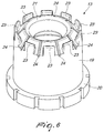
- the ring 4 is constituted by a cylindrical wall that has an open end face and an end face closed by a closure wall 6.
- the inner side of the cylindrical wall of the ring 4 is provided with an inner thread 5 that is adapted to engage the thread 3 of the cylindrical body 2.
- the closure wall 6 has a central hole 7, which allows the entry of a cable 40 to be connected to the socket.
- the inner part of the closure wall 6 has a conical plane 8 provided with anti-slip ribs 9.
- the inner thread 5 is interrupted by at least one inclined plane 10; in the illustrated example there are two inclined planes 10 in mutually opposite positions.
- An annular plane 11 is provided between the inner thread 5 and the conical plane 8 and acts as a retention member when the ring 4 is screwed onto the cylindrical body 2.
- the ring 4 has a protrusion 12 at the central hole 7.
- the assembly 1 also includes a gasket 13 and a cable presser member 14, which are arranged coaxially within the cylindrical body 2 and the ring 4.
- the cable presser member 14 is constituted by an annular member 15 and by a plurality of flexible blades 16 connected monolithically to the annular member 15.
- Each flexible blade 16 has a tooth-shaped free end 17 that protrudes inward and is adapted to grip the cable.
- the gasket 13 is constituted by a cylindrical portion 19, which has an edge 20 and, on the opposite side, a flexible lip 21 that delimits a central inlet 22.
- Anti-curl tabs 23 are provided outside the flexible lip 21 and are delimited by bending openings 24.
- the gasket 13 is arranged so that the cylindrical portion 19 is inside the cable presser member 14 so that the edge 20 is arranged between the annular member 15 of the cable presser member, and an inner annular edge 18 formed in the cylindrical body 2.
- the inner surface of the cylindrical body 2, which is in contact with the flexible blades 16 of the cable presser member 14, has a series of axial ribs 25 that have the function of preventing the rotation of the cable presser member and of the gasket 13.
- the operation of the cable gland assembly according to the present invention is as follows.
- the cable 40 is inserted in the hole 7 of the ring 4, which is in an initial position, shown in Figure 4 , in which the ring is screwed only partially onto the cylindrical body 2.
- the ring 4 is screwed onto the cylindrical body 2.
- the manual operation for screwing the ring 4 moves the ring in an axial direction, moving the conical plane 8 into contact with the tooth-shaped ends 17 of the flexible blades 16, pushing the blades toward the center of the cylindrical body 2.
- the flexible blades 16 go against the cable 40, by sliding along the conical plane 8. In this step, the annular member 15, and therefore the entire cable presser member 14, does not rotate, due to the axial ribs 25, and presses the gasket 13 against the cable 40.
- the cable presser member 14 surrounds the gasket 13, which tightens around the cable 40 by virtue of the screwing of the ring 4.
- the gasket 13 adheres perfectly to the cable 40, as shown in Figure 7 , and therefore ensures maximum tightness of the system.
- the substantially conical shape and the excellent flexibility of the flexible lip 21 ensures that it has an ability to dilate that allows the cable gland assembly to accept cables with a wide range of diameters, adapting the pressure of the gasket 13 to the actual dimensions of the cable 40.
- the anti-curl tabs 23 of the gasket 13 are located below the tooth-shaped ends 17 of the blades 16, and when the ring 4 is screwed on, the anti-curl tabs 23 are retained in position by the flexible blades 16.
- the gasket 13 maintains its position, preventing it from rolling up or collapsing due to the friction of the sheath of the cables and allowing to maintain the desired level of tightness.
Landscapes
- Engineering & Computer Science (AREA)
- Architecture (AREA)
- Civil Engineering (AREA)
- Structural Engineering (AREA)
- Installation Of Indoor Wiring (AREA)
- Connector Housings Or Holding Contact Members (AREA)
- Cable Accessories (AREA)
- Details Of Connecting Devices For Male And Female Coupling (AREA)
Claims (8)
- Ensemble de presse-étoupe comprenant un corps cylindrique (2) pourvu d'un filetage (3) adapté pour venir en prise avec une bague (4) ; ledit corps cylindrique (2) étant capable de renfermer un câble (40) connecté à un dispositif auquel ledit ensemble de presse-étoupe (1) peut être appliqué ; ladite bague (4) étant constituée par une paroi cylindrique ayant une face d'extrémité ouverte et une face d'extrémité fermée par une paroi de fermeture (6) ; le côté intérieur de la paroi cylindrique de ladite bague (4) ayant un filetage intérieur (5) adapté pour venir en prise avec ledit filetage (3) dudit corps cylindrique (2) ; ladite paroi de fermeture (6) comprenant un trou central (7) ; ledit câble (40) entrant dans ledit ensemble de presse-étoupe (1) à travers ledit trou central (7) ; ladite paroi de fermeture (6) ayant une partie intérieure constituée par un plan conique (8) ; ledit ensemble (1) comprenant un joint d'étanchéité (13) et un élément presseur de câble (14), qui sont au moins partiellement agencés à l'intérieur dudit corps cylindrique (2) ; ledit joint d'étanchéité (13) et ledit élément presseur de câble (14) étant coaxiaux et occupant un espace intérieur qui est défini par ledit bague (4) et est compris entre ledit plan conique (8) et ledit corps cylindrique (2) ; ladite bague (4) étant capable de se déplacer le long d'une direction axiale en conséquence d'un mouvement de vissage sur ledit corps cylindrique (2) ; ledit plan conique (8) agissant sur ledit élément presseur de câble (14) quand ladite bague (4) se déplace axialement, en imprimant un mouvement le long d'une direction axiale audit presseur de câble (14) et en serrant ledit presseur de câble (14) sur ledit câble (40) ; ledit joint d'étanchéité (13) étant interposé entre ledit presseur de câble (14) et ledit câble (40) ; ledit ensemble de presse-étoupe (1) étant caractérisé en ce que ledit élément de presseur de câble (14) comprend un élément annuaire (15) et une pluralité de lames flexibles (16) associées de manière monolithique audit élément annulaire (15) ; chacune desdites lames flexibles (16) ayant une extrémité libre en forme de dent (17) ; lesdites extrémités en forme de dent (17) dépassant vers l'intérieur et étant adaptées pour saisir ledit câble (40) ; ledit joint d'étanchéité (13) comprend une portion cylindrique (19) ayant un bord (20) et, sur le côté opposé, une lèvre flexible (21) ; ladite lèvre flexible (21) délimitant une entrée centrale (22) ; des languettes anti-incurvation (23) étant présentes sur l'extérieur de ladite lèvre flexible (21) et étant délimitées par des ouvertures d'incurvation (24) pendant l'opération de serrage de la bague (4), lesdites ouvertures d'incurvation (24) constituant des régions flexibles qui permettent une meilleure adaptation audit câble (40) ; lesdites languettes anti-incurvation (23) dudit joint d'étanchéité (13) étant situées au-dessous desdites extrémités en forme de dent (17) desdites lames (16), et quand ladite bague (4) est vissée, lesdites languettes anti-incurvation (23) sont retenues en position par lesdites lames flexibles (16).
- Ensemble de presse-étoupe selon la revendication 1, caractérisé en ce que ledit filetage intérieur (5) de ladite bague (4) est interrompu par au moins un plan incliné (10).
- Ensemble de presse-étoupe selon la revendication 1, caractérisé en ce qu'il comprend un plan annulaire (11) entre le filetage intérieur (5) et ledit plan conique (8) de ladite bague (4) ; ledit plan annulaire (11) agissant comme un élément de butée quand ladite bague (4) est vissée sur ledit corps cylindrique (2).
- Ensemble de presse-étoupe selon une ou plusieurs des revendications précédentes, caractérisé en ce que ladite bague (4) comprend une protubérance (12) au niveau dudit trou central (7).
- Ensemble de presse-étoupe selon une ou plusieurs des revendications précédentes, caractérisé en ce que ledit joint d'étanchéité (13) est disposé avec ladite portion cylindrique (19) à l'intérieur dudit élément presseur de câble (14) ; ledit bord (20) étant disposé entre ledit élément annuaire (15) dudit élément presseur de câble (14) et un bord annulaire intérieur (18) formé dans ledit corps cylindrique (2).
- Ensemble de presse-étoupe selon une ou plusieurs des revendications précédentes, caractérisé en ce que ladite surface intérieur dudit corps cylindrique (2) qui est en contact avec lesdites lames flexibles (16) dudit élément presseur de câble (14) comprend une pluralité de nervures axiales (25) qui empêchent la rotation dudit élément presseur de câble (14) et dudit joint d'étanchéité (13).
- Ensemble de presse-étoupe selon une ou plusieurs des revendications précédentes, caractérisé en ce que ledit plan conique (8) de ladite bague (4) comprend des nervures antidérapantes (9) ; quand ladite bague (4) est serrée sur ledit corps cylindrique (2), lesdites lames flexibles (16) étant maintenues en position par l'action desdites nervures antidérapantes (9) sur lesdites extrémités en forme de dent (1).
- Agencement comprend un ensemble de presse-étoupe selon une ou plusieurs des revendications précédentes et ledit dispositif auquel ledit ensemble de presse-étoupe est appliqué, caractérisé en ce que ledit dispositif est une prise/connecteur individuel (50) pourvu d'une peignée (51) ; ledit corps cylindrique (2) étant partie intégrante de ladite poignée (51).
Applications Claiming Priority (1)
| Application Number | Priority Date | Filing Date | Title |
|---|---|---|---|
| IT000472A ITMI20130472A1 (it) | 2013-03-28 | 2013-03-28 | Struttura di pressacavo, particolarmente per prese e spine di tipo industriale |
Publications (2)
| Publication Number | Publication Date |
|---|---|
| EP2784887A1 EP2784887A1 (fr) | 2014-10-01 |
| EP2784887B1 true EP2784887B1 (fr) | 2016-09-14 |
Family
ID=48366394
Family Applications (1)
| Application Number | Title | Priority Date | Filing Date |
|---|---|---|---|
| EP14001108.1A Active EP2784887B1 (fr) | 2013-03-28 | 2014-03-26 | Ensemble presse-étoupe pour appareil électrique |
Country Status (4)
| Country | Link |
|---|---|
| EP (1) | EP2784887B1 (fr) |
| CN (1) | CN104078792B (fr) |
| ES (1) | ES2603428T3 (fr) |
| IT (1) | ITMI20130472A1 (fr) |
Families Citing this family (4)
| Publication number | Priority date | Publication date | Assignee | Title |
|---|---|---|---|---|
| KR101702370B1 (ko) * | 2015-05-07 | 2017-02-27 | (주)뉴그린테크 | 케이블 연결 장치 |
| CN110539802A (zh) * | 2019-09-10 | 2019-12-06 | 广州博盟汽车配件有限公司 | 一种汽车发动机舱前舱连接保护罩 |
| WO2024003685A1 (fr) * | 2022-07-01 | 2024-01-04 | Scame Parre S.P.A. | Prise/fiche industrielle mobile à joint amélioré du passage de câble |
| EP4429039A1 (fr) * | 2023-03-10 | 2024-09-11 | TE Connectivity Nederland B.V. | Ensemble manchon de pincement avec élément de verrouillage |
Family Cites Families (19)
| Publication number | Priority date | Publication date | Assignee | Title |
|---|---|---|---|---|
| DE1750095A1 (de) * | 1968-03-29 | 1971-03-11 | Walter Roehl | Verschraubung fuer Kabel,Schlaeuche u.ae. |
| DE3109583A1 (de) * | 1981-03-13 | 1982-10-07 | Jacob GmbH Elektrotechnische Fabrik, 7053 Kernen | Kabelverschraubung |
| JPS59122305A (ja) * | 1982-12-25 | 1984-07-14 | 日幸工業株式会社 | ケ−ブル類の固定具 |
| DE8400007U1 (de) * | 1984-01-02 | 1984-03-29 | Olbrich, Knut, Dipl.-Kfm., 7000 Stuttgart | Elektrischer Steckverbinder |
| DE3417882A1 (de) * | 1984-05-14 | 1985-11-21 | Nikko Kogyo K.K., Tokio/Tokyo | Kabelhalter |
| DE3519032C1 (de) * | 1985-05-25 | 1986-10-30 | Anton Hummel Gmbh Metallwarenfabrik, 7808 Waldkirch | Kabelverschraubung mit einem Klemmeinsatz und einer Dichtung |
| DE3903354C1 (fr) * | 1989-02-04 | 1990-02-01 | Anton Hummel Gmbh Metallwarenfabrik, 7808 Waldkirch, De | |
| DE4127162C1 (fr) * | 1991-08-16 | 1992-11-19 | Anton Hummel Verwaltungs Gmbh, 7808 Waldkirch, De | |
| DE4238517A1 (de) * | 1992-11-14 | 1994-05-19 | Hummel Anton Verwaltung | Kabelverschraubung für Erdungs- oder Abschirm-Kabel |
| DE29700685U1 (de) * | 1997-01-16 | 1997-03-13 | Hermann Kleinhuis GmbH & Co KG, 58507 Lüdenscheid | Verschraubung aus Kunststoff |
| AU690510B3 (en) * | 1997-09-16 | 1998-04-23 | Teh-Tsung Chiu | Device for fastening a cable to a board |
| IT1318285B1 (it) | 2000-07-31 | 2003-07-28 | Gewiss Spa | Presa/spina elettrica mobile di tipo industriale. |
| AUPR447001A0 (en) * | 2001-04-19 | 2001-05-17 | Philmac Pty Ltd | Pipe coupling |
| US7014216B2 (en) * | 2003-04-29 | 2006-03-21 | Thc International, Llc | Joint assembly for flexible and semi-rigid pipings |
| EP1783876A3 (fr) * | 2005-11-04 | 2007-11-07 | Agro Ag | Presse-étoupe pour câble blindé |
| CN201038357Y (zh) * | 2007-03-26 | 2008-03-19 | 贵州航天电器股份有限公司 | 一种射频同轴电缆端接装置 |
| US7735876B2 (en) * | 2008-01-03 | 2010-06-15 | Avc Industrial Corp. | Fastening device for cable and wave hose |
| CN201774215U (zh) * | 2010-07-22 | 2011-03-23 | 全冠企业有限公司 | 电缆与波浪管防水接头 |
| CH704182A2 (de) * | 2010-12-01 | 2012-06-15 | Agro Ag | Haltevorrichtung zum halten eines kabels. |
-
2013
- 2013-03-28 IT IT000472A patent/ITMI20130472A1/it unknown
-
2014
- 2014-03-26 ES ES14001108.1T patent/ES2603428T3/es active Active
- 2014-03-26 EP EP14001108.1A patent/EP2784887B1/fr active Active
- 2014-03-28 CN CN201410255040.0A patent/CN104078792B/zh active Active
Also Published As
| Publication number | Publication date |
|---|---|
| CN104078792A (zh) | 2014-10-01 |
| ITMI20130472A1 (it) | 2014-09-29 |
| ES2603428T3 (es) | 2017-02-27 |
| EP2784887A1 (fr) | 2014-10-01 |
| CN104078792B (zh) | 2018-05-15 |
Similar Documents
| Publication | Publication Date | Title |
|---|---|---|
| JP6088623B2 (ja) | 電気コネクタアセンブリおよびエルボーコネクタアセンブリ | |
| EP2784887B1 (fr) | Ensemble presse-étoupe pour appareil électrique | |
| US10530097B2 (en) | Plug connection and set of plug connections | |
| EP3076495A1 (fr) | Connecteur flottant | |
| US8087949B2 (en) | Connector with a threaded actuator and a sealing component entirely within a nut component | |
| US9800030B2 (en) | Conduit receivers | |
| US10056746B1 (en) | Electrical slip conduit coupler | |
| US11322919B2 (en) | Cable entry device for electrical cable housed in a conduit | |
| JPH077837A (ja) | ケーブルグランド | |
| CA2890494C (fr) | Raccords et methodes de fabrication et d'utilisation desdits raccords | |
| US11451027B2 (en) | Press coupler for electrical conduit | |
| US10483742B2 (en) | Cable/lead insertion unit | |
| CN107592949B (zh) | 电缆/线缆插入装置 | |
| GB2274208A (en) | Earthed cable gland | |
| KR20220088789A (ko) | 부싱 및 부싱을 포함한 케이블 글랜드 | |
| US4501463A (en) | Cable terminal element | |
| US10676285B2 (en) | Electrical plug connector for motorized rollers | |
| US20150354739A1 (en) | Field serviceable conduit receivers | |
| WO2020087279A1 (fr) | Connecteur d'alimentation | |
| US8366459B2 (en) | Compression style mid-span ground clamp | |
| KR20210027379A (ko) | 전기 연결부를 벽에 연결하기 위한 인서트 및 인서트용 보호 캡 |
Legal Events
| Date | Code | Title | Description |
|---|---|---|---|
| 17P | Request for examination filed |
Effective date: 20140326 |
|
| AK | Designated contracting states |
Kind code of ref document: A1 Designated state(s): AL AT BE BG CH CY CZ DE DK EE ES FI FR GB GR HR HU IE IS IT LI LT LU LV MC MK MT NL NO PL PT RO RS SE SI SK SM TR |
|
| AX | Request for extension of the european patent |
Extension state: BA ME |
|
| PUAI | Public reference made under article 153(3) epc to a published international application that has entered the european phase |
Free format text: ORIGINAL CODE: 0009012 |
|
| R17P | Request for examination filed (corrected) |
Effective date: 20150226 |
|
| RBV | Designated contracting states (corrected) |
Designated state(s): AL AT BE BG CH CY CZ DE DK EE ES FI FR GB GR HR HU IE IS IT LI LT LU LV MC MK MT NL NO PL PT RO RS SE SI SK SM TR |
|
| 17Q | First examination report despatched |
Effective date: 20150715 |
|
| GRAP | Despatch of communication of intention to grant a patent |
Free format text: ORIGINAL CODE: EPIDOSNIGR1 |
|
| INTG | Intention to grant announced |
Effective date: 20160407 |
|
| GRAS | Grant fee paid |
Free format text: ORIGINAL CODE: EPIDOSNIGR3 |
|
| GRAA | (expected) grant |
Free format text: ORIGINAL CODE: 0009210 |
|
| AK | Designated contracting states |
Kind code of ref document: B1 Designated state(s): AL AT BE BG CH CY CZ DE DK EE ES FI FR GB GR HR HU IE IS IT LI LT LU LV MC MK MT NL NO PL PT RO RS SE SI SK SM TR |
|
| REG | Reference to a national code |
Ref country code: GB Ref legal event code: FG4D |
|
| REG | Reference to a national code |
Ref country code: CH Ref legal event code: EP |
|
| REG | Reference to a national code |
Ref country code: IE Ref legal event code: FG4D |
|
| REG | Reference to a national code |
Ref country code: AT Ref legal event code: REF Ref document number: 829923 Country of ref document: AT Kind code of ref document: T Effective date: 20161015 |
|
| REG | Reference to a national code |
Ref country code: DE Ref legal event code: R096 Ref document number: 602014003546 Country of ref document: DE |
|
| REG | Reference to a national code |
Ref country code: LT Ref legal event code: MG4D |
|
| REG | Reference to a national code |
Ref country code: NL Ref legal event code: MP Effective date: 20160914 |
|
| PG25 | Lapsed in a contracting state [announced via postgrant information from national office to epo] |
Ref country code: FI Free format text: LAPSE BECAUSE OF FAILURE TO SUBMIT A TRANSLATION OF THE DESCRIPTION OR TO PAY THE FEE WITHIN THE PRESCRIBED TIME-LIMIT Effective date: 20160914 Ref country code: RS Free format text: LAPSE BECAUSE OF FAILURE TO SUBMIT A TRANSLATION OF THE DESCRIPTION OR TO PAY THE FEE WITHIN THE PRESCRIBED TIME-LIMIT Effective date: 20160914 Ref country code: NO Free format text: LAPSE BECAUSE OF FAILURE TO SUBMIT A TRANSLATION OF THE DESCRIPTION OR TO PAY THE FEE WITHIN THE PRESCRIBED TIME-LIMIT Effective date: 20161214 Ref country code: HR Free format text: LAPSE BECAUSE OF FAILURE TO SUBMIT A TRANSLATION OF THE DESCRIPTION OR TO PAY THE FEE WITHIN THE PRESCRIBED TIME-LIMIT Effective date: 20160914 Ref country code: LT Free format text: LAPSE BECAUSE OF FAILURE TO SUBMIT A TRANSLATION OF THE DESCRIPTION OR TO PAY THE FEE WITHIN THE PRESCRIBED TIME-LIMIT Effective date: 20160914 |
|
| REG | Reference to a national code |
Ref country code: AT Ref legal event code: MK05 Ref document number: 829923 Country of ref document: AT Kind code of ref document: T Effective date: 20160914 |
|
| REG | Reference to a national code |
Ref country code: ES Ref legal event code: FG2A Ref document number: 2603428 Country of ref document: ES Kind code of ref document: T3 Effective date: 20170227 |
|
| PG25 | Lapsed in a contracting state [announced via postgrant information from national office to epo] |
Ref country code: SE Free format text: LAPSE BECAUSE OF FAILURE TO SUBMIT A TRANSLATION OF THE DESCRIPTION OR TO PAY THE FEE WITHIN THE PRESCRIBED TIME-LIMIT Effective date: 20160914 Ref country code: NL Free format text: LAPSE BECAUSE OF FAILURE TO SUBMIT A TRANSLATION OF THE DESCRIPTION OR TO PAY THE FEE WITHIN THE PRESCRIBED TIME-LIMIT Effective date: 20160914 Ref country code: LV Free format text: LAPSE BECAUSE OF FAILURE TO SUBMIT A TRANSLATION OF THE DESCRIPTION OR TO PAY THE FEE WITHIN THE PRESCRIBED TIME-LIMIT Effective date: 20160914 Ref country code: GR Free format text: LAPSE BECAUSE OF FAILURE TO SUBMIT A TRANSLATION OF THE DESCRIPTION OR TO PAY THE FEE WITHIN THE PRESCRIBED TIME-LIMIT Effective date: 20161215 |
|
| REG | Reference to a national code |
Ref country code: FR Ref legal event code: PLFP Year of fee payment: 4 |
|
| PG25 | Lapsed in a contracting state [announced via postgrant information from national office to epo] |
Ref country code: RO Free format text: LAPSE BECAUSE OF FAILURE TO SUBMIT A TRANSLATION OF THE DESCRIPTION OR TO PAY THE FEE WITHIN THE PRESCRIBED TIME-LIMIT Effective date: 20160914 Ref country code: EE Free format text: LAPSE BECAUSE OF FAILURE TO SUBMIT A TRANSLATION OF THE DESCRIPTION OR TO PAY THE FEE WITHIN THE PRESCRIBED TIME-LIMIT Effective date: 20160914 |
|
| PG25 | Lapsed in a contracting state [announced via postgrant information from national office to epo] |
Ref country code: BE Free format text: LAPSE BECAUSE OF FAILURE TO SUBMIT A TRANSLATION OF THE DESCRIPTION OR TO PAY THE FEE WITHIN THE PRESCRIBED TIME-LIMIT Effective date: 20160914 Ref country code: IS Free format text: LAPSE BECAUSE OF FAILURE TO SUBMIT A TRANSLATION OF THE DESCRIPTION OR TO PAY THE FEE WITHIN THE PRESCRIBED TIME-LIMIT Effective date: 20170114 Ref country code: SM Free format text: LAPSE BECAUSE OF FAILURE TO SUBMIT A TRANSLATION OF THE DESCRIPTION OR TO PAY THE FEE WITHIN THE PRESCRIBED TIME-LIMIT Effective date: 20160914 Ref country code: AT Free format text: LAPSE BECAUSE OF FAILURE TO SUBMIT A TRANSLATION OF THE DESCRIPTION OR TO PAY THE FEE WITHIN THE PRESCRIBED TIME-LIMIT Effective date: 20160914 Ref country code: PL Free format text: LAPSE BECAUSE OF FAILURE TO SUBMIT A TRANSLATION OF THE DESCRIPTION OR TO PAY THE FEE WITHIN THE PRESCRIBED TIME-LIMIT Effective date: 20160914 Ref country code: SK Free format text: LAPSE BECAUSE OF FAILURE TO SUBMIT A TRANSLATION OF THE DESCRIPTION OR TO PAY THE FEE WITHIN THE PRESCRIBED TIME-LIMIT Effective date: 20160914 Ref country code: CZ Free format text: LAPSE BECAUSE OF FAILURE TO SUBMIT A TRANSLATION OF THE DESCRIPTION OR TO PAY THE FEE WITHIN THE PRESCRIBED TIME-LIMIT Effective date: 20160914 Ref country code: PT Free format text: LAPSE BECAUSE OF FAILURE TO SUBMIT A TRANSLATION OF THE DESCRIPTION OR TO PAY THE FEE WITHIN THE PRESCRIBED TIME-LIMIT Effective date: 20170116 Ref country code: BG Free format text: LAPSE BECAUSE OF FAILURE TO SUBMIT A TRANSLATION OF THE DESCRIPTION OR TO PAY THE FEE WITHIN THE PRESCRIBED TIME-LIMIT Effective date: 20161214 |
|
| REG | Reference to a national code |
Ref country code: DE Ref legal event code: R097 Ref document number: 602014003546 Country of ref document: DE |
|
| PLBE | No opposition filed within time limit |
Free format text: ORIGINAL CODE: 0009261 |
|
| STAA | Information on the status of an ep patent application or granted ep patent |
Free format text: STATUS: NO OPPOSITION FILED WITHIN TIME LIMIT |
|
| PG25 | Lapsed in a contracting state [announced via postgrant information from national office to epo] |
Ref country code: DK Free format text: LAPSE BECAUSE OF FAILURE TO SUBMIT A TRANSLATION OF THE DESCRIPTION OR TO PAY THE FEE WITHIN THE PRESCRIBED TIME-LIMIT Effective date: 20160914 |
|
| 26N | No opposition filed |
Effective date: 20170615 |
|
| REG | Reference to a national code |
Ref country code: CH Ref legal event code: PL |
|
| PG25 | Lapsed in a contracting state [announced via postgrant information from national office to epo] |
Ref country code: MC Free format text: LAPSE BECAUSE OF FAILURE TO SUBMIT A TRANSLATION OF THE DESCRIPTION OR TO PAY THE FEE WITHIN THE PRESCRIBED TIME-LIMIT Effective date: 20160914 Ref country code: SI Free format text: LAPSE BECAUSE OF FAILURE TO SUBMIT A TRANSLATION OF THE DESCRIPTION OR TO PAY THE FEE WITHIN THE PRESCRIBED TIME-LIMIT Effective date: 20160914 |
|
| REG | Reference to a national code |
Ref country code: IE Ref legal event code: MM4A |
|
| PG25 | Lapsed in a contracting state [announced via postgrant information from national office to epo] |
Ref country code: LU Free format text: LAPSE BECAUSE OF NON-PAYMENT OF DUE FEES Effective date: 20170326 |
|
| PG25 | Lapsed in a contracting state [announced via postgrant information from national office to epo] |
Ref country code: CH Free format text: LAPSE BECAUSE OF NON-PAYMENT OF DUE FEES Effective date: 20170331 Ref country code: LI Free format text: LAPSE BECAUSE OF NON-PAYMENT OF DUE FEES Effective date: 20170331 Ref country code: IE Free format text: LAPSE BECAUSE OF NON-PAYMENT OF DUE FEES Effective date: 20170326 |
|
| REG | Reference to a national code |
Ref country code: FR Ref legal event code: PLFP Year of fee payment: 5 |
|
| PG25 | Lapsed in a contracting state [announced via postgrant information from national office to epo] |
Ref country code: MT Free format text: LAPSE BECAUSE OF NON-PAYMENT OF DUE FEES Effective date: 20170326 |
|
| PG25 | Lapsed in a contracting state [announced via postgrant information from national office to epo] |
Ref country code: AL Free format text: LAPSE BECAUSE OF FAILURE TO SUBMIT A TRANSLATION OF THE DESCRIPTION OR TO PAY THE FEE WITHIN THE PRESCRIBED TIME-LIMIT Effective date: 20160914 |
|
| PG25 | Lapsed in a contracting state [announced via postgrant information from national office to epo] |
Ref country code: HU Free format text: LAPSE BECAUSE OF FAILURE TO SUBMIT A TRANSLATION OF THE DESCRIPTION OR TO PAY THE FEE WITHIN THE PRESCRIBED TIME-LIMIT; INVALID AB INITIO Effective date: 20140326 |
|
| PG25 | Lapsed in a contracting state [announced via postgrant information from national office to epo] |
Ref country code: CY Free format text: LAPSE BECAUSE OF FAILURE TO SUBMIT A TRANSLATION OF THE DESCRIPTION OR TO PAY THE FEE WITHIN THE PRESCRIBED TIME-LIMIT Effective date: 20160914 |
|
| PG25 | Lapsed in a contracting state [announced via postgrant information from national office to epo] |
Ref country code: MK Free format text: LAPSE BECAUSE OF FAILURE TO SUBMIT A TRANSLATION OF THE DESCRIPTION OR TO PAY THE FEE WITHIN THE PRESCRIBED TIME-LIMIT Effective date: 20160914 |
|
| PG25 | Lapsed in a contracting state [announced via postgrant information from national office to epo] |
Ref country code: TR Free format text: LAPSE BECAUSE OF FAILURE TO SUBMIT A TRANSLATION OF THE DESCRIPTION OR TO PAY THE FEE WITHIN THE PRESCRIBED TIME-LIMIT Effective date: 20160914 |
|
| P01 | Opt-out of the competence of the unified patent court (upc) registered |
Effective date: 20230525 |
|
| PGFP | Annual fee paid to national office [announced via postgrant information from national office to epo] |
Ref country code: DE Payment date: 20240327 Year of fee payment: 11 Ref country code: GB Payment date: 20240327 Year of fee payment: 11 |
|
| PGFP | Annual fee paid to national office [announced via postgrant information from national office to epo] |
Ref country code: IT Payment date: 20240321 Year of fee payment: 11 Ref country code: FR Payment date: 20240325 Year of fee payment: 11 |
|
| PGFP | Annual fee paid to national office [announced via postgrant information from national office to epo] |
Ref country code: ES Payment date: 20240401 Year of fee payment: 11 |