EP2784010B1 - Recording device and conveyance device - Google Patents
Recording device and conveyance device Download PDFInfo
- Publication number
- EP2784010B1 EP2784010B1 EP14162093.0A EP14162093A EP2784010B1 EP 2784010 B1 EP2784010 B1 EP 2784010B1 EP 14162093 A EP14162093 A EP 14162093A EP 2784010 B1 EP2784010 B1 EP 2784010B1
- Authority
- EP
- European Patent Office
- Prior art keywords
- pair
- rollers
- recording
- recording medium
- paper feed
- Prior art date
- Legal status (The legal status is an assumption and is not a legal conclusion. Google has not performed a legal analysis and makes no representation as to the accuracy of the status listed.)
- Active
Links
Images


Classifications
-
- B—PERFORMING OPERATIONS; TRANSPORTING
- B65—CONVEYING; PACKING; STORING; HANDLING THIN OR FILAMENTARY MATERIAL
- B65H—HANDLING THIN OR FILAMENTARY MATERIAL, e.g. SHEETS, WEBS, CABLES
- B65H20/00—Advancing webs
- B65H20/02—Advancing webs by friction roller
-
- B—PERFORMING OPERATIONS; TRANSPORTING
- B65—CONVEYING; PACKING; STORING; HANDLING THIN OR FILAMENTARY MATERIAL
- B65H—HANDLING THIN OR FILAMENTARY MATERIAL, e.g. SHEETS, WEBS, CABLES
- B65H2301/00—Handling processes for sheets or webs
- B65H2301/40—Type of handling process
- B65H2301/44—Moving, forwarding, guiding material
- B65H2301/443—Moving, forwarding, guiding material by acting on surface of handled material
- B65H2301/4431—Moving, forwarding, guiding material by acting on surface of handled material by means with operating surfaces contacting opposite faces of material
- B65H2301/44318—Moving, forwarding, guiding material by acting on surface of handled material by means with operating surfaces contacting opposite faces of material between rollers
-
- B—PERFORMING OPERATIONS; TRANSPORTING
- B65—CONVEYING; PACKING; STORING; HANDLING THIN OR FILAMENTARY MATERIAL
- B65H—HANDLING THIN OR FILAMENTARY MATERIAL, e.g. SHEETS, WEBS, CABLES
- B65H2404/00—Parts for transporting or guiding the handled material
- B65H2404/10—Rollers
- B65H2404/14—Roller pairs
- B65H2404/147—Roller pairs both nip rollers being driven
-
- B—PERFORMING OPERATIONS; TRANSPORTING
- B65—CONVEYING; PACKING; STORING; HANDLING THIN OR FILAMENTARY MATERIAL
- B65H—HANDLING THIN OR FILAMENTARY MATERIAL, e.g. SHEETS, WEBS, CABLES
- B65H2404/00—Parts for transporting or guiding the handled material
- B65H2404/10—Rollers
- B65H2404/15—Roller assembly, particular roller arrangement
- B65H2404/152—Arrangement of roller on a movable frame
- B65H2404/1521—Arrangement of roller on a movable frame rotating, pivoting or oscillating around an axis, e.g. parallel to the roller axis
-
- B—PERFORMING OPERATIONS; TRANSPORTING
- B65—CONVEYING; PACKING; STORING; HANDLING THIN OR FILAMENTARY MATERIAL
- B65H—HANDLING THIN OR FILAMENTARY MATERIAL, e.g. SHEETS, WEBS, CABLES
- B65H2801/00—Application field
- B65H2801/03—Image reproduction devices
- B65H2801/06—Office-type machines, e.g. photocopiers
-
- B—PERFORMING OPERATIONS; TRANSPORTING
- B65—CONVEYING; PACKING; STORING; HANDLING THIN OR FILAMENTARY MATERIAL
- B65H—HANDLING THIN OR FILAMENTARY MATERIAL, e.g. SHEETS, WEBS, CABLES
- B65H2801/00—Application field
- B65H2801/03—Image reproduction devices
- B65H2801/09—Single-function copy machines
-
- B—PERFORMING OPERATIONS; TRANSPORTING
- B65—CONVEYING; PACKING; STORING; HANDLING THIN OR FILAMENTARY MATERIAL
- B65H—HANDLING THIN OR FILAMENTARY MATERIAL, e.g. SHEETS, WEBS, CABLES
- B65H2801/00—Application field
- B65H2801/03—Image reproduction devices
- B65H2801/12—Single-function printing machines, typically table-top machines
-
- B—PERFORMING OPERATIONS; TRANSPORTING
- B65—CONVEYING; PACKING; STORING; HANDLING THIN OR FILAMENTARY MATERIAL
- B65H—HANDLING THIN OR FILAMENTARY MATERIAL, e.g. SHEETS, WEBS, CABLES
- B65H2801/00—Application field
- B65H2801/03—Image reproduction devices
- B65H2801/15—Digital printing machines
-
- B—PERFORMING OPERATIONS; TRANSPORTING
- B65—CONVEYING; PACKING; STORING; HANDLING THIN OR FILAMENTARY MATERIAL
- B65H—HANDLING THIN OR FILAMENTARY MATERIAL, e.g. SHEETS, WEBS, CABLES
- B65H2801/00—Application field
- B65H2801/36—Plotting
Definitions
- the present invention relates to a device for performing processing on a medium supported in a state rolled in roll form while pulling one end.
- the recording medium was conveyed up to the recording unit, and after recording was performed on the recording medium by the recording unit, the medium was ejected to outside the device.
- a device is disclosed that is equipped with a roller that takes out a cut sheet from a housing unit, and conveys it. With this device, the cut sheet is taken out from the housing unit by rotating the roller while pressing it on the top surface of the cut sheet housed in the housing unit. Then, the conveyance means receives the cut sheet that followed the rotation of the roller and was conveyed, and conveys it (for example, see Japanese Unexamined Patent Publication No. H10-167489 ).
- WO0222362 discloses an ink jet printing device for various media, comprising a printing head device having at least one printing head for printing the medium, and a printing table for positioning and/or guiding the medium to be printed.
- the ink jet printing device also comprises an adjustment device for changing the distance between the printing head device and the medium in a direction which is perpendicular to the guiding surface; and a control device.
- a base body and/or a printing table are arranged on a machine frame, and a bearing or guiding surface for a medium is configured in one plane on either the base body or the printing table, a feeding device being arranged on one of the two, or both, for guiding through an approximately intrinsically rigid medium.
- JP2011201224 (A ) discloses a further printer
- JP H02 239964 discloses a printer having a platen and a paper feed roller formed with a thermal head split into two
- JP H01 173760 U discloses a printer fusing system e.g. for a label printer or similar printing to a continuous roll of paper.
- the device When the medium is supported in a roll form, in contrast to when conveying cut sheets, it is necessary to convey the rolled up medium while pulling it. Because of that, the device is equipped with a pair of rollers that respectively abuts the medium, and conveyance of the medium is performed by this pair of rollers abutting above and below the medium. Because of that, the constitution is such that the friction force becomes stronger when the pair of rollers is abutting the medium.
- the present invention was created considering the problems noted above, and an object is to provide a recording device and conveyance device capable of implementing suitable processing on a medium supported in a state rolled into roll form.
- the recording medium can be any item as long as it is an item that can be recorded with a recording material such as ink or the like.
- the recording unit can be any well-known item as long as it can perform recording on the recording medium.
- the movable mechanism can be any item for which abutting of any of the conveyance rollers on the recording medium can be released by changing the position of at least one of the abutting rollers, and it is also possible to change the position of all the abutting rollers.
- the relative position of the pair of abutting rollers is maintained, and they are made to abut the recording medium.
- the moving mechanism changes the position of at least one of the pair of abutting rollers, and the abutting by the pair of abutting rollers is released, the recording medium is supported on the support roller.
- the recording medium is used in a state with one end supported to be able to rotate and the other end pulled and unrolled, so by supporting the recording medium using the support roller on the conveyance path, the position of the recording medium within the conveyance path changes, and abutment with one of the pair of abutting rollers is eased.
- the pair of nipping rollers nipping the recording medium and conveying it, the recording medium is reliably aligned, and it is possible to perform recording with good precision.
- a further preferable feature is set out in claim 4.
- FIG. 1 is a side view showing an example of the key parts of the recording device for describing this technology.
- FIG. 2 is a perspective view showing the external view of a large scale inkjet printer as an example of the recording device.
- FIG. 3 is a vertical cross section diagram showing the recording device with the stacker 19 omitted.
- FIG. 4 is a block diagram for describing the constitution of the recording device.
- the recording device is realized as an inkjet printer that performs recording on roll paper (recording medium, medium to be conveyed) R1 and R2.
- the recording device 1 is equipped with a case 10, and a paper feed unit 50 provided to be able to slide in sliding direction D1 in relation to this case 10. Also, the recording device 1 is able to do printing (perform recording) while switching between the device top part interior first roll paper R1 and the device bottom part second roll paper R2. Also, the roll paper after printing, after being cut by a cutter 18, is ejected through an ejection unit 17 (R4 in FIG. 3 ), and is stacked in the stacker 19.
- the code D1 shows the slide direction of the paper feed unit 50 in relation to the case 10.
- the code D2 shows the pulling direction of the paper feed unit 50 from the housed position L1 toward the pulling position.
- the code D3 shows the housing direction of the paper feed unit 40 from the pulled state toward the housed position L1.
- the code D4 shows the height direction of the recording device 1.
- the roll paper R1 and R2 is continuous paper rolled into roll form. With the roll paper R1 and R2, the outside is the printing surface. Of course, when the position of the feeding mechanism 21 and 51 is changed, it is also possible to use roll paper for which the inside is the printing surface. For the roll paper, it is possible to use rolled sheets of various materials such as paper, cloth, plastic sheets, leather or the like.
- a recording unit 12 inside the case 10 are equipped a recording unit 12, a pair of conveyance rollers 15 and 16, a cutter 18, paths 11, 20, 30, and 40, paper feed mechanisms (21 to 26), paper feed mechanisms (51 to 57), rolling rollers 31, and a control unit 60.
- the paths in which the roll paper R1 or the roll paper R2 are fed and conveyed include a conveyance path 11, a first paper feed path 20, and second paper feed paths 30 and 40.
- the conveyance path 11 is a path for which printing is performed on the roll paper R1 (R2).
- the first paper feed path 20 is a path for feeding roll paper R1 to the pair of conveyance rollers 15 and 16.
- the second paper feed paths 30 and 40 are paths that feed the roll paper R2 to the pair of conveyance rollers 15 and 16.
- the second paper feed path 30 is a path formed proximal to the paper feed unit 50
- the second paper feed path 40 is a path formed further to the downstream side than the second paper feed path 30.
- the definition and positional relationship of the paths 11, 20, 30, and 40 are not limited to this.
- a portion of the conveyance path 11 may overlap a portion of the first paper feed path 20 or the second paper feed path 40. It is also possible to form different paths between the paths.
- the pair of conveyance rollers 15 and 16 and the recording unit 12 are arranged in the conveyance path 11.
- the pair of conveyance rollers 15 and 16 is equipped with a drive roller 15 arranged at the lower side and a driven roller 16 arranged at the upper side.
- the drive roller 15 is rotated by a conveyance motor 71 described later.
- the driven roller 16 is supported to be able to rotate, and with the drive roller 15, sandwiches the recording medium. Because of that, the driven roller 16 rotates following the roll paper R1 (R2) conveyed by the rotation of the drive roller 15.
- the recording unit 12 is arranged further to the downstream side than the pair of conveyance rollers 15 and 16 in the conveyance path 11.
- the recording unit 12 is equipped with a recording head 13 and a platen 14 that supports the conveyed roll paper R1 and R2 from beneath.
- the recording device 1 is described as a serial type printer for which the recording unit 12 is moved by a carriage (not illustrated) in the direction intersecting the direction in which the roll paper R1 and R2 is conveyed.
- the recording device 1 it is also possible for the recording device 1 to be a line head type printer.
- the first paper feed path 20 is equipped with a feeding mechanism 21 that supports the roll paper R1, a pair of paper feed rollers (abutting rollers) 22 and 23, and support rollers 24 and 25.
- the feeding mechanism 21 has the roll paper R1 supported to be able to rotate on a roll shaft. With this embodiment, the feeding mechanism 21 does not have the power to rotate the roll paper R1, but the feeding mechanism 21 can have the power to rotate the roll paper 21 in other embodiments.
- the pair of paper feed rollers 22 and 23 is equipped with a drive roller 22 arranged at the upper (or lower) side and a driven roller 23 arranged at the lower (or upper) side, sandwiching the roll paper R1 fed by the first paper feed path 20.
- the drive roller 22 rotates by the rotation of a paper feed motor 72 described later, and feeds the roll paper R1 to the conveyance path 11.
- the drive roller 22 is constituted by a rubber roller.
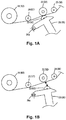
- a movable mechanism 26 supports the driven roller 23 to be able to rotate. Also, the movable mechanism 26 switches the position of the driven roller 23 between a first position near the drive roller 22, as shown in FIG. 1A , and a second position separated from the drive roller 22 shown in FIG. 1B .
- the driven roller 23 When the driven roller 23 is positioned in the first position, the driven roller 23 abuts the surface of the roll paper R1. Meanwhile, when the driven roller 23 is positioned in the second position, the abutment on the roll paper R1 is released.
- the movable mechanism 26 swings with a fulcrum 26a as a reference according to driving of a movability motor 73 described later, and switches the position of the driven roller 23 between the first position and the second position.
- this is merely one example of the constitution of the movable mechanism 26, and it is possible to be equipped with any of various mechanisms as long as it can switch the position of the driven roller 23 between the first position and the second position.
- the support rollers 24 and 25 are equipped with a first support roller 24 arranged further to the downstream side of the first paper feed path 20 than the pair of paper feed rollers 22 and 23, and a second support roller 25 arranged further to the upstream side of the first paper feed path 20 than the pair of paper feed rollers 22, 23.
- the first support roller 24 is supported to be able to rotate on the wall of the upper part of the first paper feed path 20, and juts slightly to the inside of the path from the inner surface of this wall.
- the second support roller 25 is supported to be able to rotate on the wall of the top part of the first paper feed path 20, and juts slightly to the inside of the path from the inner surface of this wall.
- the first support roller 24 and the second support roller 25 are on the same side of the roll paper R1 as the driven roller 23. Although preferred, this is not necessary and one or both may be on the same side as the drive roller 22.
- a feeding mechanism 51 that supports the second roller paper R2 is arranged on the paper feed unit 50. Also, paper feed rollers (a pair of conveyance rollers) 52 and 53, a media detection sensor 54, a movable mechanism 55, and support rollers 56 and 57 are positioned in the second paper feed path 40.
- the pair of paper feed rollers 52 and 53 is equipped with a drive roller 52 arranged at the upper (or lower) side sandwiching the roll paper R2 that is fed by the second paper feed path 40, and a driven roller 53 arranged at the lower (or upper) side.
- the drive roller 52 rotates according to the rotation of a paper feed motor 72 described later.
- the drive roller 52 is constituted using a rubber roller.
- the driven roller 53 while abutting the surface of the roll paper R1 facing opposite the drive roller 52, rotates following the roll paper R2 that is fed according to the rotation of the drive roller 52.
- the movable mechanism 55 supports the driven roller 53 to be able to rotate. Also, the same as with the movable mechanism 26 of the first paper feed path 20, the movable mechanism 55 switches the position of the driven roller 53 between the first position near the drive roller 52 ( FIG. 1A ) and the second position separated from the drive roller 52 ( FIG. 1B ).
- the drive roller and the driven roller constituting the pair of rollers may be arranged conversely from the positional relationship described above. It is also possible to have the movable mechanism switch the position of the drive roller. Also, it is possible to constitute the pair of rollers using a pair of drive rollers, using a drive roller instead of the driven roller. Furthermore, in addition to the drive roller and the driven roller abutting directly opposite surfaces the roll paper in the conveyance direction, it is also possible to have the abutting position skewed in the conveyance direction.
- the media detection sensor 54 detects whether or not the roll paper R2 is being supplied to the upstream side of the pair of paper feed rollers 52 and 53 in the second paper feed path 40.
- the support rollers 56 and 57 are equipped with a first support roller 56 arranged further to the downstream side of the second paper feed path 40 than the pair of paper feed rollers (52, 53), and a second support roller 57 arranged further to the upstream side of the second paper feed path 40 than the pair of paper feed rollers (52, 53).
- the first support roller 56 is supported to be able to rotate on the wall of the top part of the second paper feed path 40, and juts slightly to the inside of the path from the inner surface of this wall.
- the second roller 57 is supported to be able to rotate on the wall of the top part of the second paper feed path 40, and juts slightly to the inside of the path from the inner surface of this wall.
- the first support roller 56 and the second support roller 57 are on the same side of the roll paper R1 as the drive roller 52. Although preferred, this is not necessary and one or both may be on the same side as the driven roller 53.
- a plurality of rolling rollers 31 are arranged in the second paper feed path 40.
- the rolling rollers 31 support the roll paper R2 that passes through the second paper feed path 40.
- the rolling rollers 31 are supported to be able to rotate on the wall of the second paper feed path 40, and jut slightly from the inner surface of the path wall.
- the control unit 60 is equipped with a CPU (Central Processing Unit) 61, a ROM (Read Only Memory) 62, a RAM (Random Access Memory) 63, a non-volatile memory 64, a head drive circuit 65, motor drive circuits 66, 67, and 68, and an I/O interface 69.
- a control program or data to be executed by the CPU 61 are recorded in the ROM 62.
- the CPU 61 controls driving of the recording device 1 comprehensively by executing the control programs or data recorded in the ROM 62 while expanding in the RAM 63.
- job data used with print processing is recorded in the non-volatile memory 64.
- this job data is temporarily recorded in the non-volatile memory 64.
- the head drive circuit 65 is electrically connected to the recording head 13, and drives the recording head 13 by commands from the CPU 61.
- the recording head 13 is for example an inkjet recording head that sprays ink from nozzles.
- the recording head 13 sprays ink from nozzles and performs recording on the roll paper R1 (R2) by drive signals supplied from the head drive circuit 65.
- the motor drive circuits 66, 67, and 68 are respectively connected to the conveyance motor 71, the paper feed motor 72 and the movability motor 73, and drive each motor (71, 72, and 73) by commands from the CPU 61. To do that, the motor drive circuits 66, 67, and 68 function as the drivers for the motors 71, 72, and 73.
- the conveyance motor 71 is connected to the conveyance drive roller 15 via a power transmission mechanism 75. Because of that, the drive roller 15 is rotated by driving (rotation) of the conveyance motor 71.
- the paper feed motor 72 is connected to the paper feed drive roller 22 (52) via a power transmission mechanism 76. Because of that, the paper feed motor 72 rotates the driver roller 22 (52) of the pair of paper feed rollers by driving (rotation) of the paper feed motor 72.
- FIG. 4 for convenience, a constitution for which a plurality of driver rollers are connected to the power transmission mechanism 75 and 76 is described, but the invention is not limited to this.
- the movability motor 73 is connected to the movable mechanism 26 (55) via a power transmission mechanism 77. Because of that, the movable mechanism 26 (55) moves by driving (rotation) of the movability motor 73, and the position of the driver roller 23 (53) of the pair of paper feed rollers is changed.
- the I/O interface 69 is connected to the media detection sensor 54 and an encoder 72a attached to the paper feed motor 72.
- the media detection sensor 54 detects the presence or absence of the roll paper R2.
- the media detection sensor 54 is constituted by a well-known sensor such as an optical sensor or the like, for example.
- the encoder 72a converts the rotation count of the paper feed motor 72 to pulse signals and outputs that. Because of that, the I/O interface 69 receives the respective output from the media detection sensor 54 and the encoder 72a, and is able to output that to the CPU 61.
- FIG. 5 is a flow chart describing the printing process flow.
- the user inserts the pulled tip part of the roll paper R2 from an insertion port (not shown) toward the interval between rollers of the pair of paper feed rollers 52 and 53.
- the movable mechanism 55 holds the position of the driven roller 53 in the first position. Specifically, the drive roller 52 and the driven roller 53 are near each other.
- step S1: Yes the control unit 60 rotates the paper feed motor 72. Because of that, the drive roller 52 to which the rotation of the paper feed motor 72 is transmitted starts rotating. In this state, when the tip of the roll paper R2 reaches between the drive roller 52 and the driven roller 53, the pair of paper feed rollers 52 and 53 pull in the roll paper R2.
- the tip of the pulled in roll paper R2 penetrates the second paper feed path 30 in a state supported on the support rollers 56 and 57. Then, by rotation of the drive roller 52 continuing, the tip of the roll paper R2 passes through the second paper feed path 40, and reaches the conveyance path 11.
- the paper feed of the pair of paper feed rollers 52 and 53 continues until the tip of the roll paper R2 reaches the pair of conveyance rollers 15 and 16 inside the conveyance path 11 (step S3).
- the control unit 60 makes a judgment based on the rotation count detected by the encoder 72a connected to the paper feed motor 72. Specifically, the rotation count N1 of the paper feed motor 72 according to the paper feed distance of the fed roll paper R2 is recorded in the ROM 62.
- the roll paper R2 paper feed distance is the distance from the pair of paper feed rollers 52 and 53 to the conveyance rollers 15 and 16.
- step S4 the control unit 60 drives the conveyance motor 71.
- the pair of conveyance rollers 15 and 16 are rotated by the driving of the conveyance motor 71, and the tip of the roll paper R2 is pulled to the recording head 13 side. Also, the roll paper R2 is sandwiched respectively from the top and bottom by the pair of conveyance rollers 15 and 16.
- the control unit 60 drives the movability motor 73, and switches the position of the driven roller 53 of the pair of paper feed rollers.
- the movable mechanism 55 is moved by the rotation of the movability motor 73, and the position of the driven roller 53 is changed to the second position ( FIG. 1B ).
- the driven roller 53 being at a position separated from the roll paper R2, the abutting of the pair of paper feed rollers 52 and 53 on the roll paper R2 is released.
- FIG. 6 is a drawing for describing changes in the roll paper path with the first position and the second position.
- the position of the roll paper R2 positioned in the second paper feed path 40 (PI) differs from the position when abutting the pair of paper feed rollers 52 and 53 (P2).
- the top (inner) surface UP of the roll paper R2 abutting and being supported (stretched) respectively by the first support roller 56 and the second support roller 57, the position of the roll paper R2 is changed.
- the path of the roll paper R2 positioned in the second paper feed path 30 becomes a position at which the drive roller 52 and the driven roller 53 are separated and not in contact, and it is possible to suppress the effect due to friction that occurs by contact of the pair of paper feed rollers 52 and 53.
- stretching between two points is not essential.
- at least one of the support rollers 56, 57 is in the same transport path 30 as the pair of paper feed rollers 52, 53 to the extent the manner in which it supports the roll paper R2 is different in the first and second positions. Strictly, although preferred, neither of the support rollers 56, 57 need support the roll paper R2 in the first position.
- step S6 the control unit 60 drives the recording head 13, and recording is performed on the roll paper R2. Specifically, while the pair of conveyance rollers 15, 16 sandwiches the roll paper R2, the tip of the roll paper R2 is conveyed onto the platen 14. Then, the control unit 60 moves the recording head 13 back and forth in the main scan direction based on job data recorded in the non-volatile memory 64, and records ink on the roll paper R2.
- step S7 the control unit 60 determines whether or not the printing process has ended.
- step S7: No since the printing of the final raster data of the recording image included in the job data has not ended (step S7: No), the process returns to step S6, and the conveyance of the roll paper R2 by the pair of conveyance rollers 15 and 16 and recording by the recording head 13 are continued.
- step S7: Yes when the printing of the final raster data of the recording image has ended (step S7: Yes), at step S8, the control unit 60 drives the cutter 18 and cuts the roll paper R2. Because of that, the tip of the cut roll paper R2 is ejected by its own weight, and is housed in stacker 19.
- step S9 the control unit 60 stops driving of the conveyance motor 71. Also, at step S10, the control unit 60 drives the movability motor 73, and drives the movable mechanism 55 so that the driven roller 53 is positioned at the first position.
- the movable mechanism holds the pair of paper feed rollers at a position sandwiching the roll paper. Meanwhile, when the movable mechanism releases abutting of the roll paper by the pair of paper feed rollers, the roll paper is supported on the support rollers and is conveyed within the path.
- the position within the roll paper path changes, and the abutting with the pair of paper feed rollers is eased.
- the roll paper is reliably aligned during conveyance, and it is possible to perform recording with good precision.
- the control unit 60 may store the rotation count needed to move the tip of the paper from the cutter 18 to (or slightly beyond) the pair of conveyance rollers 15, 16.
- both the drive roller and driven roller constituting the pair of paper feed rollers are sheltered by the movable mechanism.
- this kind of constitution regardless of the position of the support rollers 56 and 57, during conveyance by the pair of conveyance rollers 15 and 16, it is possible to reliably separate roll paper from the pair of conveyance rollers 15 and 16. Because of that, it is possible to perform design of the paper feed path with more flexibility.
- the present invention can also have various modification examples.
- the use of the pair of rollers as the conveyance unit is merely an example.
- the conveyance means in any form as long as it is capable of conveying a medium.
- the recording device can also be a device that performs recording on one recording medium.
- the recording device can be another printer such as a laser printer or the like, or a combination machine such as a fax machine or the like.
Description
- This application claims priority to Japanese Patent Application No.
2013-071623 filed on March 29, 2013 - The present invention relates to a device for performing processing on a medium supported in a state rolled in roll form while pulling one end.
- In the past, with the recording device of a printing device or the like, the recording medium was conveyed up to the recording unit, and after recording was performed on the recording medium by the recording unit, the medium was ejected to outside the device. For example, a device is disclosed that is equipped with a roller that takes out a cut sheet from a housing unit, and conveys it. With this device, the cut sheet is taken out from the housing unit by rotating the roller while pressing it on the top surface of the cut sheet housed in the housing unit. Then, the conveyance means receives the cut sheet that followed the rotation of the roller and was conveyed, and conveys it (for example, see Japanese Unexamined Patent Publication No.
H10-167489 -
WO0222362 (A2 JP2011201224 (A JP H02 239964 JP H01 173760 U - When the medium is supported in a roll form, in contrast to when conveying cut sheets, it is necessary to convey the rolled up medium while pulling it. Because of that, the device is equipped with a pair of rollers that respectively abuts the medium, and conveyance of the medium is performed by this pair of rollers abutting above and below the medium. Because of that, the constitution is such that the friction force becomes stronger when the pair of rollers is abutting the medium.
- However, in a state with contact between the pair of rollers and the medium being continuous, when processing is implemented on this medium, there are cases when friction force between the roller and the medium is strong, and processing is performed with the medium left in an unreasonable orientation, or in some cases, when the medium is damaged.
- The present invention was created considering the problems noted above, and an object is to provide a recording device and conveyance device capable of implementing suitable processing on a medium supported in a state rolled into roll form.
- According to one aspect of the present invention, there is provided a recording device according to
claim 1. - Here, the recording medium can be any item as long as it is an item that can be recorded with a recording material such as ink or the like.
- Also, the recording unit can be any well-known item as long as it can perform recording on the recording medium.
- Also, the movable mechanism can be any item for which abutting of any of the conveyance rollers on the recording medium can be released by changing the position of at least one of the abutting rollers, and it is also possible to change the position of all the abutting rollers.
- With the aspect as noted above, during conveyance of the recording medium by the pair of abutting rollers, the relative position of the pair of abutting rollers is maintained, and they are made to abut the recording medium. Meanwhile, when the moving mechanism changes the position of at least one of the pair of abutting rollers, and the abutting by the pair of abutting rollers is released, the recording medium is supported on the support roller. Here, the recording medium is used in a state with one end supported to be able to rotate and the other end pulled and unrolled, so by supporting the recording medium using the support roller on the conveyance path, the position of the recording medium within the conveyance path changes, and abutment with one of the pair of abutting rollers is eased.
- Because of that, since the abutment with the abutting roller is eased, it is possible to perform recording of the recording medium without the recording medium being in an unreasonable orientation, or having damage occur.
- With the arrangement of
claim 1, by the pair of nipping rollers nipping the recording medium and conveying it, the recording medium is reliably aligned, and it is possible to perform recording with good precision. - With the arrangement of
claim 1, it is possible to suppress forcing of an unreasonable orientation or unreasonable force being applied to the recording medium due to interference between the nipping of the pair of nipping rollers and the abutting of the pair of abutting rollers. - According to a second aspect of the present invention, there is provided a recording device according to claim 2.
- With the arrangement of claim 2, it is possible to ease the effect by the pair of abutting rollers during recording.
- It is also possible to have a constitution that further includes an additional support roller, and the recording medium is stretched across the support roller and the additional support roller in the released state.
- With this arrangement as noted above, when abutting of the pair of abutting rollers is released, the recording medium is stretched (bridged) across the first support roller and the second support roller, so the recording medium is positioned separated from the pair of abutting rollers. As a result, it is possible to suppress the occurrence of friction that occurs with abutting of the pair of abutting rollers on the recording medium.
- A further preferable feature is set out in
claim 4. - Embodiments of the present invention will now be described by way of further example only and with reference to the accompanying drawings, in which:
-
FIGS. 1A and 1B are side views showing an example of parts of a recording device for describing an example of the embodiment. -
FIG. 2 is a perspective view showing the external view of a large size inkjet printer as an example of a recording device. -
FIG. 3 is a vertical cross section diagram showing the recording device with the stacker omitted. -
FIG. 4 is a block diagram for describing the constitution of the recording device. -
FIG. 5 is a flow chart for describing the flow of the printing process. -
FIG. 6 is a drawing for explaining the changes in the roll paper path of the first position and the second position. - Hereafter, we will describe embodiments of the present invention in the following sequence: 1. First Embodiment; 2. Second Embodiment; and 3. Other Embodiments.
-
FIG. 1 is a side view showing an example of the key parts of the recording device for describing this technology. Also,FIG. 2 is a perspective view showing the external view of a large scale inkjet printer as an example of the recording device. Then,FIG. 3 is a vertical cross section diagram showing the recording device with thestacker 19 omitted. Furthermore,FIG. 4 is a block diagram for describing the constitution of the recording device. - With this first embodiment, the recording device is realized as an inkjet printer that performs recording on roll paper (recording medium, medium to be conveyed) R1 and R2.
- As shown in
FIG. 2 , therecording device 1 is equipped with acase 10, and apaper feed unit 50 provided to be able to slide in sliding direction D1 in relation to thiscase 10. Also, therecording device 1 is able to do printing (perform recording) while switching between the device top part interior first roll paper R1 and the device bottom part second roll paper R2. Also, the roll paper after printing, after being cut by acutter 18, is ejected through an ejection unit 17 (R4 inFIG. 3 ), and is stacked in thestacker 19. - In the drawing described above, the code D1 shows the slide direction of the
paper feed unit 50 in relation to thecase 10. The code D2 shows the pulling direction of thepaper feed unit 50 from the housed position L1 toward the pulling position. Also, the code D3 shows the housing direction of thepaper feed unit 40 from the pulled state toward the housed position L1. Then, the code D4 shows the height direction of therecording device 1. - The roll paper R1 and R2 is continuous paper rolled into roll form. With the roll paper R1 and R2, the outside is the printing surface. Of course, when the position of the
feeding mechanism - Also, as shown in
FIG. 3 and the like, inside thecase 10 are equipped arecording unit 12, a pair ofconveyance rollers cutter 18,paths rollers 31, and acontrol unit 60. - The paths in which the roll paper R1 or the roll paper R2 are fed and conveyed include a
conveyance path 11, a firstpaper feed path 20, and secondpaper feed paths conveyance path 11 is a path for which printing is performed on the roll paper R1 (R2). Also, the firstpaper feed path 20 is a path for feeding roll paper R1 to the pair ofconveyance rollers paper feed paths conveyance rollers paper feed path 30 is a path formed proximal to thepaper feed unit 50, and the secondpaper feed path 40 is a path formed further to the downstream side than the secondpaper feed path 30. - The definition and positional relationship of the
paths conveyance path 11 to overlap a portion of the firstpaper feed path 20 or the secondpaper feed path 40. It is also possible to form different paths between the paths. - The pair of
conveyance rollers recording unit 12 are arranged in theconveyance path 11. - The pair of
conveyance rollers drive roller 15 arranged at the lower side and a drivenroller 16 arranged at the upper side. Thedrive roller 15 is rotated by aconveyance motor 71 described later. Also, the drivenroller 16 is supported to be able to rotate, and with thedrive roller 15, sandwiches the recording medium. Because of that, the drivenroller 16 rotates following the roll paper R1 (R2) conveyed by the rotation of thedrive roller 15. - The
recording unit 12 is arranged further to the downstream side than the pair ofconveyance rollers conveyance path 11. Therecording unit 12 is equipped with arecording head 13 and aplaten 14 that supports the conveyed roll paper R1 and R2 from beneath. With this embodiment, therecording device 1 is described as a serial type printer for which therecording unit 12 is moved by a carriage (not illustrated) in the direction intersecting the direction in which the roll paper R1 and R2 is conveyed. However, it is also possible for therecording device 1 to be a line head type printer. - The first
paper feed path 20 is equipped with afeeding mechanism 21 that supports the roll paper R1, a pair of paper feed rollers (abutting rollers) 22 and 23, andsupport rollers - The
feeding mechanism 21 has the roll paper R1 supported to be able to rotate on a roll shaft. With this embodiment, thefeeding mechanism 21 does not have the power to rotate the roll paper R1, but thefeeding mechanism 21 can have the power to rotate theroll paper 21 in other embodiments. - The pair of
paper feed rollers drive roller 22 arranged at the upper (or lower) side and a drivenroller 23 arranged at the lower (or upper) side, sandwiching the roll paper R1 fed by the firstpaper feed path 20. Thedrive roller 22 rotates by the rotation of apaper feed motor 72 described later, and feeds the roll paper R1 to theconveyance path 11. For example, thedrive roller 22 is constituted by a rubber roller. Also, the drivenroller 23, while together with thedrive roller 22 abutting the respective opposite surfaces of the roll paper R1, rotates following the roll paper R1 that is paper fed according to the rotation of thedrive roller 22. - A
movable mechanism 26 supports the drivenroller 23 to be able to rotate. Also, themovable mechanism 26 switches the position of the drivenroller 23 between a first position near thedrive roller 22, as shown inFIG. 1A , and a second position separated from thedrive roller 22 shown inFIG. 1B . When the drivenroller 23 is positioned in the first position, the drivenroller 23 abuts the surface of the roll paper R1. Meanwhile, when the drivenroller 23 is positioned in the second position, the abutment on the roll paper R1 is released. - With this first embodiment, the
movable mechanism 26 swings with afulcrum 26a as a reference according to driving of amovability motor 73 described later, and switches the position of the drivenroller 23 between the first position and the second position. Of course, this is merely one example of the constitution of themovable mechanism 26, and it is possible to be equipped with any of various mechanisms as long as it can switch the position of the drivenroller 23 between the first position and the second position. - The
support rollers first support roller 24 arranged further to the downstream side of the firstpaper feed path 20 than the pair ofpaper feed rollers second support roller 25 arranged further to the upstream side of the firstpaper feed path 20 than the pair ofpaper feed rollers first support roller 24 is supported to be able to rotate on the wall of the upper part of the firstpaper feed path 20, and juts slightly to the inside of the path from the inner surface of this wall. Thesecond support roller 25 is supported to be able to rotate on the wall of the top part of the firstpaper feed path 20, and juts slightly to the inside of the path from the inner surface of this wall. In the embodiment, thefirst support roller 24 and thesecond support roller 25 are on the same side of the roll paper R1 as the drivenroller 23. Although preferred, this is not necessary and one or both may be on the same side as thedrive roller 22. - Also, a
feeding mechanism 51 that supports the second roller paper R2 is arranged on thepaper feed unit 50. Also, paper feed rollers (a pair of conveyance rollers) 52 and 53, amedia detection sensor 54, amovable mechanism 55, andsupport rollers paper feed path 40. - The pair of
paper feed rollers drive roller 52 arranged at the upper (or lower) side sandwiching the roll paper R2 that is fed by the secondpaper feed path 40, and a drivenroller 53 arranged at the lower (or upper) side. Thedrive roller 52 rotates according to the rotation of apaper feed motor 72 described later. For example, thedrive roller 52 is constituted using a rubber roller. - Also, the driven
roller 53, while abutting the surface of the roll paper R1 facing opposite thedrive roller 52, rotates following the roll paper R2 that is fed according to the rotation of thedrive roller 52. - The
movable mechanism 55 supports the drivenroller 53 to be able to rotate. Also, the same as with themovable mechanism 26 of the firstpaper feed path 20, themovable mechanism 55 switches the position of the drivenroller 53 between the first position near the drive roller 52 (FIG. 1A ) and the second position separated from the drive roller 52 (FIG. 1B ). - The drive roller and the driven roller constituting the pair of rollers may be arranged conversely from the positional relationship described above. It is also possible to have the movable mechanism switch the position of the drive roller. Also, it is possible to constitute the pair of rollers using a pair of drive rollers, using a drive roller instead of the driven roller. Furthermore, in addition to the drive roller and the driven roller abutting directly opposite surfaces the roll paper in the conveyance direction, it is also possible to have the abutting position skewed in the conveyance direction.
- The
media detection sensor 54 detects whether or not the roll paper R2 is being supplied to the upstream side of the pair ofpaper feed rollers paper feed path 40. - The
support rollers first support roller 56 arranged further to the downstream side of the secondpaper feed path 40 than the pair of paper feed rollers (52, 53), and asecond support roller 57 arranged further to the upstream side of the secondpaper feed path 40 than the pair of paper feed rollers (52, 53). Thefirst support roller 56 is supported to be able to rotate on the wall of the top part of the secondpaper feed path 40, and juts slightly to the inside of the path from the inner surface of this wall. Thesecond roller 57 is supported to be able to rotate on the wall of the top part of the secondpaper feed path 40, and juts slightly to the inside of the path from the inner surface of this wall. In this embodiment, thefirst support roller 56 and thesecond support roller 57 are on the same side of the roll paper R1 as thedrive roller 52. Although preferred, this is not necessary and one or both may be on the same side as the drivenroller 53. - A plurality of rolling
rollers 31 are arranged in the secondpaper feed path 40. The rollingrollers 31 support the roll paper R2 that passes through the secondpaper feed path 40. The rollingrollers 31 are supported to be able to rotate on the wall of the secondpaper feed path 40, and jut slightly from the inner surface of the path wall. - As shown in
FIG. 4 , thecontrol unit 60 is equipped with a CPU (Central Processing Unit) 61, a ROM (Read Only Memory) 62, a RAM (Random Access Memory) 63, anon-volatile memory 64, ahead drive circuit 65,motor drive circuits O interface 69. A control program or data to be executed by the CPU 61 are recorded in theROM 62. The CPU 61 controls driving of therecording device 1 comprehensively by executing the control programs or data recorded in theROM 62 while expanding in theRAM 63. - Also, job data used with print processing is recorded in the
non-volatile memory 64. For example, when thecontrol unit 60 receives job data from an external device such as a personal computer or the like (not illustrated), this job data is temporarily recorded in thenon-volatile memory 64. - The
head drive circuit 65 is electrically connected to therecording head 13, and drives therecording head 13 by commands from the CPU 61. Therecording head 13 is for example an inkjet recording head that sprays ink from nozzles. Therecording head 13 sprays ink from nozzles and performs recording on the roll paper R1 (R2) by drive signals supplied from thehead drive circuit 65. - The
motor drive circuits conveyance motor 71, thepaper feed motor 72 and themovability motor 73, and drive each motor (71, 72, and 73) by commands from the CPU 61. To do that, themotor drive circuits motors - The
conveyance motor 71 is connected to theconveyance drive roller 15 via apower transmission mechanism 75. Because of that, thedrive roller 15 is rotated by driving (rotation) of theconveyance motor 71. - The
paper feed motor 72 is connected to the paper feed drive roller 22 (52) via apower transmission mechanism 76. Because of that, thepaper feed motor 72 rotates the driver roller 22 (52) of the pair of paper feed rollers by driving (rotation) of thepaper feed motor 72. - In
FIG. 4 , for convenience, a constitution for which a plurality of driver rollers are connected to thepower transmission mechanism - The
movability motor 73 is connected to the movable mechanism 26 (55) via apower transmission mechanism 77. Because of that, the movable mechanism 26 (55) moves by driving (rotation) of themovability motor 73, and the position of the driver roller 23 (53) of the pair of paper feed rollers is changed. - Also, the I/
O interface 69 is connected to themedia detection sensor 54 and anencoder 72a attached to thepaper feed motor 72. Themedia detection sensor 54 detects the presence or absence of the roll paper R2. Themedia detection sensor 54 is constituted by a well-known sensor such as an optical sensor or the like, for example. Also, theencoder 72a converts the rotation count of thepaper feed motor 72 to pulse signals and outputs that. Because of that, the I/O interface 69 receives the respective output from themedia detection sensor 54 and theencoder 72a, and is able to output that to the CPU 61. - Next, we will describe the printing process executed by the
recording device 1. With the printing process described hereafter, we will describe a printing process using the second roll paper R2. Note that the same method can also be used for the printing process using the first roll paper R1.FIG. 5 is a flow chart describing the printing process flow. - First, the user inserts the pulled tip part of the roll paper R2 from an insertion port (not shown) toward the interval between rollers of the pair of
paper feed rollers movable mechanism 55 holds the position of the drivenroller 53 in the first position. Specifically, thedrive roller 52 and the drivenroller 53 are near each other. - Then, when the
media detection sensor 54 detects the roll paper R2 inserted by the user (step S1: Yes), thecontrol unit 60 rotates thepaper feed motor 72. Because of that, thedrive roller 52 to which the rotation of thepaper feed motor 72 is transmitted starts rotating. In this state, when the tip of the roll paper R2 reaches between thedrive roller 52 and the drivenroller 53, the pair ofpaper feed rollers - Then, the tip of the pulled in roll paper R2 penetrates the second
paper feed path 30 in a state supported on thesupport rollers drive roller 52 continuing, the tip of the roll paper R2 passes through the secondpaper feed path 40, and reaches theconveyance path 11. Here, the paper feed of the pair ofpaper feed rollers conveyance rollers - As a method of detecting that the tip of the roll paper R2 has reached the pair of
conveyance rollers control unit 60 makes a judgment based on the rotation count detected by theencoder 72a connected to thepaper feed motor 72. Specifically, the rotation count N1 of thepaper feed motor 72 according to the paper feed distance of the fed roll paper R2 is recorded in theROM 62. With this first embodiment, the roll paper R2 paper feed distance is the distance from the pair ofpaper feed rollers conveyance rollers - Also, in addition to this, it is also possible to provide a sensor that detects the roll paper R1 and R2 further to the downstream side than the pair of
conveyance rollers conveyance path 11. - Then, when the tip of the roll paper R2 reaches the pair of
conveyance rollers control unit 60 drives theconveyance motor 71. The pair ofconveyance rollers conveyance motor 71, and the tip of the roll paper R2 is pulled to therecording head 13 side. Also, the roll paper R2 is sandwiched respectively from the top and bottom by the pair ofconveyance rollers - At step S5, the
control unit 60 drives themovability motor 73, and switches the position of the drivenroller 53 of the pair of paper feed rollers. Themovable mechanism 55 is moved by the rotation of themovability motor 73, and the position of the drivenroller 53 is changed to the second position (FIG. 1B ). By the drivenroller 53 being at a position separated from the roll paper R2, the abutting of the pair ofpaper feed rollers -
FIG. 6 is a drawing for describing changes in the roll paper path with the first position and the second position. As shown inFIG. 6 , in a state with the abutting by the pair ofpaper feed rollers paper feed rollers 52 and 53 (P2). InFIG. 6 , by the top (inner) surface UP of the roll paper R2 abutting and being supported (stretched) respectively by thefirst support roller 56 and thesecond support roller 57, the position of the roll paper R2 is changed. - As a result, since the pair of
paper feed rollers recording head 13 performs recording, or when the pair ofconveyance rollers conveyance path 11, the roll paper R2 is not put in an unreasonable orientation or damaged. - In particular, by the roll paper R2 being supported (stretched) at two points by the
first support roller 56 and thesecond support roller 57, the path of the roll paper R2 positioned in the secondpaper feed path 30 becomes a position at which thedrive roller 52 and the drivenroller 53 are separated and not in contact, and it is possible to suppress the effect due to friction that occurs by contact of the pair ofpaper feed rollers support rollers same transport path 30 as the pair ofpaper feed rollers support rollers - Then, returning to
FIG. 5 , at step S6, thecontrol unit 60 drives therecording head 13, and recording is performed on the roll paper R2. Specifically, while the pair ofconveyance rollers platen 14. Then, thecontrol unit 60 moves therecording head 13 back and forth in the main scan direction based on job data recorded in thenon-volatile memory 64, and records ink on the roll paper R2. - At step S7, the
control unit 60 determines whether or not the printing process has ended. Here, since the printing of the final raster data of the recording image included in the job data has not ended (step S7: No), the process returns to step S6, and the conveyance of the roll paper R2 by the pair ofconveyance rollers recording head 13 are continued. On the other hand, when the printing of the final raster data of the recording image has ended (step S7: Yes), at step S8, thecontrol unit 60 drives thecutter 18 and cuts the roll paper R2. Because of that, the tip of the cut roll paper R2 is ejected by its own weight, and is housed instacker 19. - Then, at step S9, the
control unit 60 stops driving of theconveyance motor 71. Also, at step S10, thecontrol unit 60 drives themovability motor 73, and drives themovable mechanism 55 so that the drivenroller 53 is positioned at the first position. - As described above, with this first embodiment, during paper feeding of the roll paper by the pair of paper feed rollers, the movable mechanism holds the pair of paper feed rollers at a position sandwiching the roll paper. Meanwhile, when the movable mechanism releases abutting of the roll paper by the pair of paper feed rollers, the roll paper is supported on the support rollers and is conveyed within the path. Here, by the pulled tip side of the roll paper supported in a state rolled in roll form being supported by the support rollers, the position within the roll paper path changes, and the abutting with the pair of paper feed rollers is eased.
- Because of that, even when recording is performed on the roll paper, and it is conveyed, there is no putting the roll paper in an unreasonable orientation or having force applied, and it is possible to do suitable recording.
- Also, by the pair of conveyance rollers sandwiching the roll paper, the roll paper is reliably aligned during conveyance, and it is possible to perform recording with good precision.
- Also, when conveyance of the roll paper by the pair of conveyance rollers is started, by releasing abutting of the pair of paper feed rollers on the roll paper, it is possible to inhibit forcing of an unreasonable orientation as well as application of unreasonable force on the roll paper due to interference between the sandwiching of the pair of conveyance rollers and the abutting of the pair of paper feed rollers.
- Then, during recording on the roll paper, by the movable mechanism releasing abutting of the paper feed rollers on the roll paper, it is possible to ease the effect by the pair of paper feed rollers during recording. In the event that the roll paper R2 is already disposed in the
second paths paper feed rollers conveyance roller control unit 60 may store the rotation count needed to move the tip of the paper from thecutter 18 to (or slightly beyond) the pair ofconveyance rollers - It is also possible to constitute this such that both the drive roller and driven roller constituting the pair of paper feed rollers are sheltered by the movable mechanism. By using this kind of constitution, regardless of the position of the
support rollers conveyance rollers conveyance rollers - The present invention can also have various modification examples.
- The use of the pair of rollers as the conveyance unit is merely an example. For example, it is also possible to constitute the conveyance means in any form as long as it is capable of conveying a medium.
- Also, in addition to being a device that switches a plurality of media to be recorded and performs recording, the recording device can also be a device that performs recording on one recording medium.
- Also, using an inkjet printer as the recording device is merely an example. The recording device can be another printer such as a laser printer or the like, or a combination machine such as a fax machine or the like.
Claims (4)
- A recording device (1) including a recording unit (12) configured and arranged to perform recording on a recording medium (R2) with the recording medium being stored in a rolled state and unrolled from one end, the recording device comprising:a pair of abutting rollers (52, 53) facing each other, and configured and arranged to convey the recording medium while the recording medium is nipped between the pair of abutting rollers;a support roller (56) arranged on a downstream side of the pair of abutting rollers in a conveyance path along which the recording medium is conveyed, the support roller being configured and arranged to abut the recording medium to support the recording medium; anda movable mechanism (55) configured and arranged to change a position of at least one (53) of the pair of abutting rollers to switch between an abutting state in which the other (52) of the pair of abutting rollers abuts the recording medium and a released state in which the other of the pair of abutting rollers does not abut the recording medium; characterised in that:the recording device further comprises a pair of nipping rollers (15, 16) arranged on the downstream side of the support roller in the conveyance path,wherein the pair of nipping rollers is configured and arranged to nip the recording medium therebetween to convey the recording medium, andwherein the movable mechanism is configured and arranged to switch to the released state when the pair of nipping rollers starts conveying the recording medium.
- A recording device (1) including a recording unit (12) configured and arranged to perform recording on a recording medium (R2) with the recording medium being stored in a rolled state and unrolled from one end, the recording device comprising:a pair of abutting rollers (52, 53) facing each other, and configured and arranged to convey the recording medium while the recording medium is nipped between the pair of abutting rollers;a support roller (56) arranged on a downstream side of the pair of abutting rollers in a conveyance path along which the recording medium is conveyed, the support roller being configured and arranged to abut the recording medium to support the recording medium; anda movable mechanism (55) configured and arranged to change a position of at least one (53) of the pair of abutting rollers to switch between an abutting state in which the other (52) of the pair of abutting rollers abuts the recording medium and a released state in which the other of the pair of abutting rollers does not abut the recording medium; characterised in that:
the movable mechanism is configured and arranged to switch to the released state during recording by the recording unit on the recording medium. - The recording device of claim 1 or claim 2, further comprising an additional support roller (57), wherein
the recording medium is stretched across the support roller (56) and the additional support roller (57) in the released state. - The recording device of claim 3, wherein
the additional support roller (57) is arranged on an upstream side of the pair of abutting rollers (52, 53) in the conveyance path.
Applications Claiming Priority (1)
| Application Number | Priority Date | Filing Date | Title |
|---|---|---|---|
| JP2013071623A JP6107317B2 (en) | 2013-03-29 | 2013-03-29 | Recording device, transport device |
Publications (2)
| Publication Number | Publication Date |
|---|---|
| EP2784010A1 EP2784010A1 (en) | 2014-10-01 |
| EP2784010B1 true EP2784010B1 (en) | 2019-01-09 |
Family
ID=50433951
Family Applications (1)
| Application Number | Title | Priority Date | Filing Date |
|---|---|---|---|
| EP14162093.0A Active EP2784010B1 (en) | 2013-03-29 | 2014-03-27 | Recording device and conveyance device |
Country Status (4)
| Country | Link |
|---|---|
| US (1) | US9878866B2 (en) |
| EP (1) | EP2784010B1 (en) |
| JP (1) | JP6107317B2 (en) |
| CN (1) | CN104070847B (en) |
Families Citing this family (3)
| Publication number | Priority date | Publication date | Assignee | Title |
|---|---|---|---|---|
| NO2848399T3 (en) * | 2013-09-13 | 2018-02-10 | ||
| EP3436270B1 (en) * | 2016-08-18 | 2021-12-08 | Hewlett-Packard Development Company, L.P. | Clamps |
| IT201600127319A1 (en) * | 2016-12-16 | 2018-06-16 | Futura Spa | Process and plant for the production of paper material logs. |
Citations (1)
| Publication number | Priority date | Publication date | Assignee | Title |
|---|---|---|---|---|
| JPH01173760U (en) * | 1988-05-27 | 1989-12-11 |
Family Cites Families (23)
| Publication number | Priority date | Publication date | Assignee | Title |
|---|---|---|---|---|
| JPS5512253U (en) * | 1978-07-07 | 1980-01-25 | ||
| JPS60148756U (en) * | 1984-03-13 | 1985-10-02 | ミノルタ株式会社 | Roll paper feeder |
| JPS61257852A (en) | 1985-11-21 | 1986-11-15 | Minolta Camera Co Ltd | Feeder for rolled paper |
| JP2857166B2 (en) * | 1989-04-28 | 1999-02-10 | 株式会社リコー | Recording device |
| JP2819595B2 (en) * | 1989-03-14 | 1998-10-30 | 富士通株式会社 | Multiple thermal printer |
| JPH0441271A (en) * | 1990-06-07 | 1992-02-12 | Brother Ind Ltd | Sheet-feeding device for printer |
| EP0747226B1 (en) | 1991-12-20 | 1998-09-02 | Seiko Epson Corporation | Printer |
| JP3186814B2 (en) | 1991-12-20 | 2001-07-11 | セイコーエプソン株式会社 | Small printer |
| TW307822B (en) * | 1994-03-11 | 1997-06-11 | Xeikon Nv | |
| JPH0891653A (en) * | 1994-09-28 | 1996-04-09 | Shinko Seisakusho Co Ltd | Printer |
| JP2004042669A (en) * | 1995-07-28 | 2004-02-12 | Fuji Photo Film Co Ltd | Color thermal printer |
| JP3576726B2 (en) | 1996-12-04 | 2004-10-13 | キヤノン株式会社 | Sheet feeding device and image forming apparatus provided with the sheet feeding device |
| EP0842880B1 (en) | 1996-11-18 | 2003-10-29 | Canon Kabushiki Kaisha | Image forming apparatus |
| IT1316139B1 (en) | 2000-09-15 | 2003-03-28 | Durst Phototechnik Ag | INK-JET PRINTING DEVICE. |
| US7229167B2 (en) * | 2001-10-05 | 2007-06-12 | Konica Corporation | Ink jet recording apparatus, ink-jet recording method and ink jet recording medium |
| US6908189B2 (en) * | 2001-10-05 | 2005-06-21 | Konica Corporation | Ink jet recording apparatus, ink-jet recording method and ink jet recording medium |
| JP3770242B2 (en) * | 2003-03-05 | 2006-04-26 | ブラザー工業株式会社 | Recording medium roll cassette and image forming apparatus |
| JP4559873B2 (en) * | 2005-02-28 | 2010-10-13 | 日本電産サンキョー株式会社 | Card-like medium transport mechanism |
| JP2008302536A (en) * | 2007-06-06 | 2008-12-18 | Canon Inc | Paper carrying device and image forming device |
| JP2011201224A (en) * | 2010-03-26 | 2011-10-13 | Seiko Epson Corp | Printer |
| JP5587048B2 (en) | 2010-06-18 | 2014-09-10 | キヤノン株式会社 | Image forming apparatus and paper feed roller driving method |
| JP5585289B2 (en) * | 2010-08-10 | 2014-09-10 | セイコーエプソン株式会社 | Conveying apparatus and recording apparatus |
| US9180690B2 (en) * | 2011-02-08 | 2015-11-10 | Xerox Corporation | System and method for decurling media in a printing system |
-
2013
- 2013-03-29 JP JP2013071623A patent/JP6107317B2/en active Active
-
2014
- 2014-03-24 US US14/223,213 patent/US9878866B2/en active Active
- 2014-03-25 CN CN201410113689.9A patent/CN104070847B/en active Active
- 2014-03-27 EP EP14162093.0A patent/EP2784010B1/en active Active
Patent Citations (1)
| Publication number | Priority date | Publication date | Assignee | Title |
|---|---|---|---|---|
| JPH01173760U (en) * | 1988-05-27 | 1989-12-11 |
Also Published As
| Publication number | Publication date |
|---|---|
| JP6107317B2 (en) | 2017-04-05 |
| CN104070847B (en) | 2018-06-15 |
| EP2784010A1 (en) | 2014-10-01 |
| US20140291375A1 (en) | 2014-10-02 |
| JP2014195895A (en) | 2014-10-16 |
| CN104070847A (en) | 2014-10-01 |
| US9878866B2 (en) | 2018-01-30 |
Similar Documents
| Publication | Publication Date | Title |
|---|---|---|
| US10377603B2 (en) | Sheet supplying apparatus and printing apparatus | |
| US8967755B2 (en) | Image forming apparatus | |
| CN108146069B (en) | Printing device | |
| JP2007145485A (en) | Recording medium carrying mechanism and image recorder having this mechanism | |
| JP4577378B2 (en) | Sheet conveying apparatus and image recording apparatus | |
| EP2784010B1 (en) | Recording device and conveyance device | |
| JP2011011488A (en) | Image forming system | |
| JP4985678B2 (en) | Image recording device | |
| JP4752940B2 (en) | Sheet conveying apparatus and image recording apparatus | |
| JP4518160B2 (en) | Sheet conveying apparatus and image recording apparatus | |
| JP6146080B2 (en) | Recording device | |
| JP2011110803A (en) | Image recording apparatus, and controlling method of image recording apparatus | |
| JP2017189946A (en) | printer | |
| JP4302670B2 (en) | Image forming apparatus | |
| JP2002254740A (en) | Method for preventing contamination in recording medium feeding of image forming device, and image forming device | |
| JP5355267B2 (en) | Recording device | |
| US8651478B2 (en) | Sheet conveying device and recording apparatus | |
| JP6669412B2 (en) | Printing equipment | |
| JP2009208272A (en) | Image recording device | |
| JP6903952B2 (en) | Transport device | |
| JP4139299B2 (en) | RECORDING BODY CUTTING DEVICE AND IMAGE RECORDING DEVICE HAVING THE RECORDING BODY CUTTING DEVICE | |
| JP5732813B2 (en) | Recording device | |
| CN103935125A (en) | Recording Apparatus | |
| JP2008062437A (en) | Recording apparatus, and its controlling method | |
| CN116265241A (en) | Printing apparatus and control method for printing apparatus |
Legal Events
| Date | Code | Title | Description |
|---|---|---|---|
| 17P | Request for examination filed |
Effective date: 20140327 |
|
| AK | Designated contracting states |
Kind code of ref document: A1 Designated state(s): AL AT BE BG CH CY CZ DE DK EE ES FI FR GB GR HR HU IE IS IT LI LT LU LV MC MK MT NL NO PL PT RO RS SE SI SK SM TR |
|
| AX | Request for extension of the european patent |
Extension state: BA ME |
|
| PUAI | Public reference made under article 153(3) epc to a published international application that has entered the european phase |
Free format text: ORIGINAL CODE: 0009012 |
|
| R17P | Request for examination filed (corrected) |
Effective date: 20150331 |
|
| RBV | Designated contracting states (corrected) |
Designated state(s): AL AT BE BG CH CY CZ DE DK EE ES FI FR GB GR HR HU IE IS IT LI LT LU LV MC MK MT NL NO PL PT RO RS SE SI SK SM TR |
|
| STAA | Information on the status of an ep patent application or granted ep patent |
Free format text: STATUS: EXAMINATION IS IN PROGRESS |
|
| 17Q | First examination report despatched |
Effective date: 20180125 |
|
| GRAP | Despatch of communication of intention to grant a patent |
Free format text: ORIGINAL CODE: EPIDOSNIGR1 |
|
| STAA | Information on the status of an ep patent application or granted ep patent |
Free format text: STATUS: GRANT OF PATENT IS INTENDED |
|
| INTG | Intention to grant announced |
Effective date: 20181008 |
|
| GRAS | Grant fee paid |
Free format text: ORIGINAL CODE: EPIDOSNIGR3 |
|
| GRAA | (expected) grant |
Free format text: ORIGINAL CODE: 0009210 |
|
| STAA | Information on the status of an ep patent application or granted ep patent |
Free format text: STATUS: THE PATENT HAS BEEN GRANTED |
|
| AK | Designated contracting states |
Kind code of ref document: B1 Designated state(s): AL AT BE BG CH CY CZ DE DK EE ES FI FR GB GR HR HU IE IS IT LI LT LU LV MC MK MT NL NO PL PT RO RS SE SI SK SM TR |
|
| REG | Reference to a national code |
Ref country code: GB Ref legal event code: FG4D |
|
| REG | Reference to a national code |
Ref country code: CH Ref legal event code: EP Ref country code: AT Ref legal event code: REF Ref document number: 1087033 Country of ref document: AT Kind code of ref document: T Effective date: 20190115 |
|
| REG | Reference to a national code |
Ref country code: IE Ref legal event code: FG4D |
|
| REG | Reference to a national code |
Ref country code: DE Ref legal event code: R096 Ref document number: 602014039427 Country of ref document: DE |
|
| REG | Reference to a national code |
Ref country code: NL Ref legal event code: MP Effective date: 20190109 |
|
| REG | Reference to a national code |
Ref country code: LT Ref legal event code: MG4D |
|
| PG25 | Lapsed in a contracting state [announced via postgrant information from national office to epo] |
Ref country code: NL Free format text: LAPSE BECAUSE OF FAILURE TO SUBMIT A TRANSLATION OF THE DESCRIPTION OR TO PAY THE FEE WITHIN THE PRESCRIBED TIME-LIMIT Effective date: 20190109 |
|
| REG | Reference to a national code |
Ref country code: AT Ref legal event code: MK05 Ref document number: 1087033 Country of ref document: AT Kind code of ref document: T Effective date: 20190109 |
|
| PG25 | Lapsed in a contracting state [announced via postgrant information from national office to epo] |
Ref country code: ES Free format text: LAPSE BECAUSE OF FAILURE TO SUBMIT A TRANSLATION OF THE DESCRIPTION OR TO PAY THE FEE WITHIN THE PRESCRIBED TIME-LIMIT Effective date: 20190109 Ref country code: SE Free format text: LAPSE BECAUSE OF FAILURE TO SUBMIT A TRANSLATION OF THE DESCRIPTION OR TO PAY THE FEE WITHIN THE PRESCRIBED TIME-LIMIT Effective date: 20190109 Ref country code: PT Free format text: LAPSE BECAUSE OF FAILURE TO SUBMIT A TRANSLATION OF THE DESCRIPTION OR TO PAY THE FEE WITHIN THE PRESCRIBED TIME-LIMIT Effective date: 20190509 Ref country code: NO Free format text: LAPSE BECAUSE OF FAILURE TO SUBMIT A TRANSLATION OF THE DESCRIPTION OR TO PAY THE FEE WITHIN THE PRESCRIBED TIME-LIMIT Effective date: 20190409 Ref country code: FI Free format text: LAPSE BECAUSE OF FAILURE TO SUBMIT A TRANSLATION OF THE DESCRIPTION OR TO PAY THE FEE WITHIN THE PRESCRIBED TIME-LIMIT Effective date: 20190109 Ref country code: LT Free format text: LAPSE BECAUSE OF FAILURE TO SUBMIT A TRANSLATION OF THE DESCRIPTION OR TO PAY THE FEE WITHIN THE PRESCRIBED TIME-LIMIT Effective date: 20190109 Ref country code: PL Free format text: LAPSE BECAUSE OF FAILURE TO SUBMIT A TRANSLATION OF THE DESCRIPTION OR TO PAY THE FEE WITHIN THE PRESCRIBED TIME-LIMIT Effective date: 20190109 |
|
| PG25 | Lapsed in a contracting state [announced via postgrant information from national office to epo] |
Ref country code: BG Free format text: LAPSE BECAUSE OF FAILURE TO SUBMIT A TRANSLATION OF THE DESCRIPTION OR TO PAY THE FEE WITHIN THE PRESCRIBED TIME-LIMIT Effective date: 20190409 Ref country code: IS Free format text: LAPSE BECAUSE OF FAILURE TO SUBMIT A TRANSLATION OF THE DESCRIPTION OR TO PAY THE FEE WITHIN THE PRESCRIBED TIME-LIMIT Effective date: 20190509 Ref country code: HR Free format text: LAPSE BECAUSE OF FAILURE TO SUBMIT A TRANSLATION OF THE DESCRIPTION OR TO PAY THE FEE WITHIN THE PRESCRIBED TIME-LIMIT Effective date: 20190109 Ref country code: LV Free format text: LAPSE BECAUSE OF FAILURE TO SUBMIT A TRANSLATION OF THE DESCRIPTION OR TO PAY THE FEE WITHIN THE PRESCRIBED TIME-LIMIT Effective date: 20190109 Ref country code: RS Free format text: LAPSE BECAUSE OF FAILURE TO SUBMIT A TRANSLATION OF THE DESCRIPTION OR TO PAY THE FEE WITHIN THE PRESCRIBED TIME-LIMIT Effective date: 20190109 Ref country code: GR Free format text: LAPSE BECAUSE OF FAILURE TO SUBMIT A TRANSLATION OF THE DESCRIPTION OR TO PAY THE FEE WITHIN THE PRESCRIBED TIME-LIMIT Effective date: 20190410 |
|
| REG | Reference to a national code |
Ref country code: DE Ref legal event code: R097 Ref document number: 602014039427 Country of ref document: DE |
|
| PG25 | Lapsed in a contracting state [announced via postgrant information from national office to epo] |
Ref country code: IT Free format text: LAPSE BECAUSE OF FAILURE TO SUBMIT A TRANSLATION OF THE DESCRIPTION OR TO PAY THE FEE WITHIN THE PRESCRIBED TIME-LIMIT Effective date: 20190109 Ref country code: EE Free format text: LAPSE BECAUSE OF FAILURE TO SUBMIT A TRANSLATION OF THE DESCRIPTION OR TO PAY THE FEE WITHIN THE PRESCRIBED TIME-LIMIT Effective date: 20190109 Ref country code: CZ Free format text: LAPSE BECAUSE OF FAILURE TO SUBMIT A TRANSLATION OF THE DESCRIPTION OR TO PAY THE FEE WITHIN THE PRESCRIBED TIME-LIMIT Effective date: 20190109 Ref country code: RO Free format text: LAPSE BECAUSE OF FAILURE TO SUBMIT A TRANSLATION OF THE DESCRIPTION OR TO PAY THE FEE WITHIN THE PRESCRIBED TIME-LIMIT Effective date: 20190109 Ref country code: AT Free format text: LAPSE BECAUSE OF FAILURE TO SUBMIT A TRANSLATION OF THE DESCRIPTION OR TO PAY THE FEE WITHIN THE PRESCRIBED TIME-LIMIT Effective date: 20190109 Ref country code: DK Free format text: LAPSE BECAUSE OF FAILURE TO SUBMIT A TRANSLATION OF THE DESCRIPTION OR TO PAY THE FEE WITHIN THE PRESCRIBED TIME-LIMIT Effective date: 20190109 Ref country code: MC Free format text: LAPSE BECAUSE OF FAILURE TO SUBMIT A TRANSLATION OF THE DESCRIPTION OR TO PAY THE FEE WITHIN THE PRESCRIBED TIME-LIMIT Effective date: 20190109 Ref country code: SK Free format text: LAPSE BECAUSE OF FAILURE TO SUBMIT A TRANSLATION OF THE DESCRIPTION OR TO PAY THE FEE WITHIN THE PRESCRIBED TIME-LIMIT Effective date: 20190109 Ref country code: AL Free format text: LAPSE BECAUSE OF FAILURE TO SUBMIT A TRANSLATION OF THE DESCRIPTION OR TO PAY THE FEE WITHIN THE PRESCRIBED TIME-LIMIT Effective date: 20190109 |
|
| REG | Reference to a national code |
Ref country code: CH Ref legal event code: PL |
|
| PLBE | No opposition filed within time limit |
Free format text: ORIGINAL CODE: 0009261 |
|
| STAA | Information on the status of an ep patent application or granted ep patent |
Free format text: STATUS: NO OPPOSITION FILED WITHIN TIME LIMIT |
|
| PG25 | Lapsed in a contracting state [announced via postgrant information from national office to epo] |
Ref country code: LU Free format text: LAPSE BECAUSE OF NON-PAYMENT OF DUE FEES Effective date: 20190327 Ref country code: SM Free format text: LAPSE BECAUSE OF FAILURE TO SUBMIT A TRANSLATION OF THE DESCRIPTION OR TO PAY THE FEE WITHIN THE PRESCRIBED TIME-LIMIT Effective date: 20190109 |
|
| REG | Reference to a national code |
Ref country code: BE Ref legal event code: MM Effective date: 20190331 |
|
| 26N | No opposition filed |
Effective date: 20191010 |
|
| PG25 | Lapsed in a contracting state [announced via postgrant information from national office to epo] |
Ref country code: LI Free format text: LAPSE BECAUSE OF NON-PAYMENT OF DUE FEES Effective date: 20190331 Ref country code: CH Free format text: LAPSE BECAUSE OF NON-PAYMENT OF DUE FEES Effective date: 20190331 Ref country code: IE Free format text: LAPSE BECAUSE OF NON-PAYMENT OF DUE FEES Effective date: 20190327 |
|
| PG25 | Lapsed in a contracting state [announced via postgrant information from national office to epo] |
Ref country code: SI Free format text: LAPSE BECAUSE OF FAILURE TO SUBMIT A TRANSLATION OF THE DESCRIPTION OR TO PAY THE FEE WITHIN THE PRESCRIBED TIME-LIMIT Effective date: 20190109 Ref country code: BE Free format text: LAPSE BECAUSE OF NON-PAYMENT OF DUE FEES Effective date: 20190331 |
|
| PG25 | Lapsed in a contracting state [announced via postgrant information from national office to epo] |
Ref country code: TR Free format text: LAPSE BECAUSE OF FAILURE TO SUBMIT A TRANSLATION OF THE DESCRIPTION OR TO PAY THE FEE WITHIN THE PRESCRIBED TIME-LIMIT Effective date: 20190109 |
|
| PG25 | Lapsed in a contracting state [announced via postgrant information from national office to epo] |
Ref country code: MT Free format text: LAPSE BECAUSE OF NON-PAYMENT OF DUE FEES Effective date: 20190327 |
|
| PG25 | Lapsed in a contracting state [announced via postgrant information from national office to epo] |
Ref country code: CY Free format text: LAPSE BECAUSE OF FAILURE TO SUBMIT A TRANSLATION OF THE DESCRIPTION OR TO PAY THE FEE WITHIN THE PRESCRIBED TIME-LIMIT Effective date: 20190109 |
|
| PG25 | Lapsed in a contracting state [announced via postgrant information from national office to epo] |
Ref country code: HU Free format text: LAPSE BECAUSE OF FAILURE TO SUBMIT A TRANSLATION OF THE DESCRIPTION OR TO PAY THE FEE WITHIN THE PRESCRIBED TIME-LIMIT; INVALID AB INITIO Effective date: 20140327 |
|
| PG25 | Lapsed in a contracting state [announced via postgrant information from national office to epo] |
Ref country code: MK Free format text: LAPSE BECAUSE OF FAILURE TO SUBMIT A TRANSLATION OF THE DESCRIPTION OR TO PAY THE FEE WITHIN THE PRESCRIBED TIME-LIMIT Effective date: 20190109 |
|
| PGFP | Annual fee paid to national office [announced via postgrant information from national office to epo] |
Ref country code: FR Payment date: 20230208 Year of fee payment: 10 |
|
| PGFP | Annual fee paid to national office [announced via postgrant information from national office to epo] |
Ref country code: GB Payment date: 20230202 Year of fee payment: 10 Ref country code: DE Payment date: 20230131 Year of fee payment: 10 |