EP2783645B1 - Fluid ejection device and medical apparatus - Google Patents
Fluid ejection device and medical apparatus Download PDFInfo
- Publication number
- EP2783645B1 EP2783645B1 EP14161974.2A EP14161974A EP2783645B1 EP 2783645 B1 EP2783645 B1 EP 2783645B1 EP 14161974 A EP14161974 A EP 14161974A EP 2783645 B1 EP2783645 B1 EP 2783645B1
- Authority
- EP
- European Patent Office
- Prior art keywords
- fluid
- drive voltage
- volume
- ejection device
- ejected
- Prior art date
- Legal status (The legal status is an assumption and is not a legal conclusion. Google has not performed a legal analysis and makes no representation as to the accuracy of the status listed.)
- Active
Links
- 239000012530 fluid Substances 0.000 title claims description 289
- 230000010349 pulsation Effects 0.000 claims description 30
- 230000000694 effects Effects 0.000 claims description 11
- 230000008859 change Effects 0.000 claims description 7
- 230000007246 mechanism Effects 0.000 description 18
- 230000004048 modification Effects 0.000 description 18
- 238000012986 modification Methods 0.000 description 18
- 230000008030 elimination Effects 0.000 description 15
- 238000003379 elimination reaction Methods 0.000 description 15
- 230000007423 decrease Effects 0.000 description 8
- 230000000630 rising effect Effects 0.000 description 5
- 230000009467 reduction Effects 0.000 description 4
- 239000000725 suspension Substances 0.000 description 4
- 238000006073 displacement reaction Methods 0.000 description 3
- 230000008901 benefit Effects 0.000 description 2
- 230000006872 improvement Effects 0.000 description 2
- 238000004519 manufacturing process Methods 0.000 description 2
- 239000002504 physiological saline solution Substances 0.000 description 2
- 238000005266 casting Methods 0.000 description 1
- 238000004140 cleaning Methods 0.000 description 1
- 230000008602 contraction Effects 0.000 description 1
- 230000001419 dependent effect Effects 0.000 description 1
- 239000003814 drug Substances 0.000 description 1
- 229940079593 drug Drugs 0.000 description 1
- 230000005489 elastic deformation Effects 0.000 description 1
- 230000001771 impaired effect Effects 0.000 description 1
- 239000007788 liquid Substances 0.000 description 1
- 239000002184 metal Substances 0.000 description 1
- 238000000034 method Methods 0.000 description 1
- 230000002093 peripheral effect Effects 0.000 description 1
- 230000003014 reinforcing effect Effects 0.000 description 1
- 239000011347 resin Substances 0.000 description 1
- 229920005989 resin Polymers 0.000 description 1
- 239000000243 solution Substances 0.000 description 1
- XLYOFNOQVPJJNP-UHFFFAOYSA-N water Substances O XLYOFNOQVPJJNP-UHFFFAOYSA-N 0.000 description 1
Images


Classifications
-
- A—HUMAN NECESSITIES
- A61—MEDICAL OR VETERINARY SCIENCE; HYGIENE
- A61B—DIAGNOSIS; SURGERY; IDENTIFICATION
- A61B17/00—Surgical instruments, devices or methods, e.g. tourniquets
- A61B17/32—Surgical cutting instruments
- A61B17/3203—Fluid jet cutting instruments
-
- A—HUMAN NECESSITIES
- A61—MEDICAL OR VETERINARY SCIENCE; HYGIENE
- A61B—DIAGNOSIS; SURGERY; IDENTIFICATION
- A61B17/00—Surgical instruments, devices or methods, e.g. tourniquets
- A61B2017/00017—Electrical control of surgical instruments
- A61B2017/00137—Details of operation mode
- A61B2017/00154—Details of operation mode pulsed
-
- A—HUMAN NECESSITIES
- A61—MEDICAL OR VETERINARY SCIENCE; HYGIENE
- A61B—DIAGNOSIS; SURGERY; IDENTIFICATION
- A61B2560/00—Constructional details of operational features of apparatus; Accessories for medical measuring apparatus
- A61B2560/02—Operational features
Definitions
- the present invention relates to a fluid ejection device and a medical apparatus using the fluid ejection device.
- JP-A-2008-82202 As a medical apparatus which ejects a fluid to a living tissue of a patient for treatment, for example, a device disclosed in JP-A-2008-82202 is known.
- a piezoelectric element is driven to increase or decrease the volume of a fluid chamber, thus causing a pulsating flow (pulse flow) to be ejected from an ejection tube.
- EP 2 286 745 A2 discloses a fluid ejection method including the steps of supplying fluid to a pressure chamber, generating a pulsed flow by varying the volume of the pressure chamber and ejecting the pulsed flow.
- a fluid ejection device is used, for example, as a surgical knife, a stable sense of use is demanded of the fluid ejection device. There is also a demand that failure to eject a proper pulsating flow due to a shortage of a fluid supplied to the fluid ejection device should be restrained. Moreover, there is a demand that staying of a fluid at the affected part due to excess supply of the fluid to the fluid ejection device should be restrained.
- An advantage of some aspects of the invention is to solve at least a part of the problems described above.
- This fluid ejection device includes: an ejection tube which ejects the fluid; a fluid chamber which communicates with the ejection tube; a fluid supplying unit which supplies the fluid to the fluid chamber at a predetermined flow rate; a pulsation generator which causes the fluid in the fluid chamber to be ejected from the ejection tube; and a controller which controls operation of the pulsation generator to cause the fluid to be ejected periodically from the ejection tube.
- the fluid supplying unit supplies the fluid at the predetermined flow rate above V1 ⁇ fmax [ml/s].
- the fluid supplying unit may supply the fluid at the predetermined flow rate below V1 ⁇ 2.0 ⁇ fmax [ml/s]. According to this fluid ejection device, excess supply of the fluid to the fluid chamber can be restrained.
- the fluid supplying unit may supply the fluid at the predetermined flow rate equal to or above (V1+V2) ⁇ fmax [ml/s]. According to this fluid ejection device , the fluid can be supplied to the fluid chamber at a proper flow rate in consideration of the inertial effect of the fluid.
- the volume V2 may be V1 ⁇ 0.007. According to this fluid ejection device, the fluid can be supplied to the fluid chamber at a proper flow rate in consideration of the inertial effect of the fluid.
- Another embodiment of the invention provides a medical apparatus using the fluid ejection device of the aspect described above. According to this, a highly reliable medical apparatus can be provided.
- the fluid supplying unit may be formed as a fluid supplying unit which supplies the fluid at the predetermined flow rate above Vlxfmax [ml/s], if the maximum frequency of the drive voltage is fmax [Hz] and the amount of change in the volume of the fluid chamber when the drive voltage of the maximum value is applied to a piezoelectric element to drive the piezoelectric element is V1 [ml].
- a device can be realized, for example, as a fluid ejection device which ejects a fluid but can also be realized as another device but not only the fluid ejection device which ejects a fluid.
- At least one of the various problems such as a reduction in the size of the device, a reduction in cost, resource saving, easier manufacturing, and improvement in usability can be solved.
- a part of all of the technical features of each aspect of the foregoing fluid ejection device which ejects a fluid can be applied to this device.
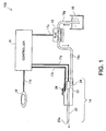
- FIG. 1 is an explanatory view showing the configuration of a fluid ejection device 100 as an embodiment of the invention.
- the fluid ejection device 100 of this embodiment is a medical apparatus used in a medical institution and has the function of a surgical knife which ejects a fluid to a living tissue of an affected part of a patient and thereby performs treatment such as incision or excision of the affect part.
- the fluid ejection device 100 has a fluid container 10, a fluid supplying mechanism 12, a handpiece 14, a controller 16, and a foot switch 18.
- the fluid container 10 and the fluid supplying mechanism 12 are connected to each other by a connection tube 19a.
- the fluid supplying mechanism 12 and the handpiece 14 are connected to each other by a connection tube 19b.
- the connection tubes 19a, 19b are made of a resin.
- the fluid container 10 houses a physiological saline solution as a fluid to be supplied to the handpiece 14.
- the fluid container 10 may house another fluid that is harmless when ejected to a living tissue, for example, pure water, a drug solution or the like, instead of the physiological saline solution.
- the fluid supplying mechanism 12 supplies the fluid housed in the fluid container 10 to the handpiece 14 via the connection tubes 19a, 19b.
- a pump is used as the fluid supplying mechanism 12.
- the fluid supplying mechanism 12 supplies the fluid to the handpiece 14 at a predetermined flow rate.
- the handpiece 14 is an instrument which the operator holds in the hand and operates.
- the handpiece 14 has a fluid ejection tube 20, a pulsation generator 22, a casing 24, and a condition switching unit 26.
- a fluid is supplied to the pulsation generator 22 via the connection tube 19b.
- the pulsation generator 22 When a drive voltage is applied to the pulsation generator 22 from the controller 16 via a voltage application cable 17a, the pulsation generator 22 generates pulsation in the supplied fluid.
- the fluid in which pulsation is generated is ejected at a high speed from an opening 20a at the forward end of the fluid ejection tube 20.
- the operator applies the fluid in which pulsation is generated and which is ejected from the handpiece 14, to a living tissue of an affected part of a patient, thereby performing treatment such as incision or excision of the affected part.
- the fluid in which pulsation is generated is also called a pulsating flow or pulse flow.
- the condition switching unit 26 is an operation unit for the operator to switch the magnitude and frequency of the drive voltage applied to the pulsation generator 22.
- a dial-type selection unit is employed as the condition switching unit 26, and the operator selects a magnitude and frequency of the drive voltage used for treatment, from predefined magnitudes and frequencies of the drive voltage.
- the magnitude of the drive voltage that is available to be set is changed.
- the frequency of the drive voltage is changed.
- the magnitude of the drive voltage that is available to be set and the frequency of the drive voltage that is available to be set are as follows. Magnitude of drive voltage available to be set: 0 V to 100 V Frequency of drive voltage available to be set: 100 Hz to 400 Hz
- the maximum value available to be set Emax of the drive voltage is 100 V
- the maximum frequency available to be set fmax of the drive voltage is 400 Hz.
- the controller 16 receives information about the magnitude and frequency of the drive voltage from the condition switching unit 26 via a control cable 17b and applies the drive voltage that satisfies the condition designated by the condition switching unit 26 to the pulsation generator 22 via the voltage application cable 17a.
- the controller 16 also controls the start and stop of the fluid supplying mechanism 12 via a control cable 17c.
- the foot switch 18 is a switch which the operator operates with the foot and is connected to the controller 16 via a control cable 17d. As the operator turns on the foot switch 18, the controller 16 instructs the fluid supplying mechanism 12 to start supplying the fluid, and applies the drive voltage to the pulsation generator 22. Then, the fluid in which pulsation is generated is ejected at a high speed from the opening 20a at the forward end of the fluid ejection tube 20 of the handpiece 14.
- FIG. 2 is an enlarged cross-sectional view showing a part of the inner configuration of the handpiece 14.
- the pulsation generator 22 which generates pulsation in the fluid supplied from the fluid supplying mechanism 12 is provided inside the casing 24 of the handpiece 14.
- the pulsation generator 22 has a piezoelectric element 30, a diaphragm 32, a first case 34, a second case 36, and a third case 38.
- an inlet channel 40, a fluid chamber 42, and an outlet channel 44 are formed as a channel through which the fluid supplied from the fluid supplying mechanism 12 passes.
- the inlet channel 40 and the outlet channel 44 are formed in the first case 34.
- the fluid chamber 42 is formed between the first case 34 and the diaphragm 32.
- the connection tube 19b is connected to the inlet channel 40.
- the fluid ejection tube 20 is connected to the outlet channel 44.
- the diaphragm 32 is a disc-shaped thin metal plate and an outer peripheral part thereof is held and fixed between the first case 34 and the second case 36.
- the piezoelectric element 30 is an actuator which operates on receiving the drive voltage applied from the controller 16.
- the piezoelectric element 30 changes the volume of the fluid chamber 42 formed between the diaphragm 32 and the first case 34, thereby changing the pressure of the fluid in the fluid chamber 42.
- the piezoelectric element 30 is a multilayer piezoelectric element, with one end thereof fixed to the diaphragm 32 and the other end thereof fixed to the third case 38.
- the piezoelectric element 30 expands.
- the diaphragm 32 is pushed by the piezoelectric element 30 and flexes toward the fluid chamber 42.
- the volume of the fluid chamber 42 decreases and the fluid in the fluid chamber 42 is extruded from the fluid chamber 42.
- the inner diameter of the outlet channel 44 is greater than the inner diameter of the inlet channel 40. That is, since the inertance of the outlet channel 44 is smaller than the inertance of the inlet channel 40, the fluid in the fluid chamber 42 is extruded from the fluid chamber 42 through the outlet channel 44.
- the piezoelectric element 30 contracts and the volume of the fluid chamber 42 increases.
- the fluid is supplied into the fluid chamber 42 from the inlet channel 40.
- the drive voltage applied to the piezoelectric element 30 repeats on-state (maximum voltage) and off-state (0 V) at a high frequency (for example, 400 Hz), an increase and decrease in the volume of the fluid chamber 42 is repeated, thus generating pulsation in the fluid.
- the fluid extruded from the fluid chamber 42 is ejected from the nozzle 20a (opening 20a) at the forward end of the fluid ejection tube 20.
- FIG. 3 is an explanatory view showing an example of the waveform of the drive voltage applied to the piezoelectric element 30.
- the horizontal axis represents time and the vertical axis represents drive voltage.
- One cycle of the waveform of the drive voltage includes a rising period during which the voltage increases, a falling period during which the voltage decreases, and a suspension period during which no voltage is applied.
- the waveform in the rising period of the drive voltage is a SIN waveform 1/2-cycle waveform that is offset in the direction of positive voltage, with the phase thereof shifted by -90 degrees.
- the waveform in the falling period of the drive voltage is a SIN waveform 1/2-cycle waveform that is offset in the direction of positive voltage, with the phase thereof shifted by +90 degrees.
- the cycle of the SIN waveform in the falling period is greater than the cycle of the SIN waveform in the rising period.
- FIG. 4 is an explanatory view showing the correspondence between the waveform of the drive voltage and how the diaphragm 32 is deformed.
- a reinforcing member 51 is provided between the piezoelectric element 30 and the diaphragm 32.
- the piezoelectric element 30 does not expand and the diaphragm 32 does not flex.
- the piezoelectric element 30 expands and the diaphragm 32 flexes toward the fluid chamber 42.
- the volume of the fluid chamber 42 decreases.
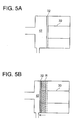
- FIGS. 5A and 5B are explanatory views schematically showing a change in the volume of the fluid chamber 42.
- FIG. 5A shows the state where no drive voltage is applied to the piezoelectric element 30 and the volume of the fluid chamber 42 is at its maximum.
- FIG. 5B shows the state where the drive voltage applied to the piezoelectric element 30 is at its maximum and the volume of the fluid chamber 42 is at its minimum.
- a hatched area R in FIG. 5B represents the volume of the fluid chamber 42 changing during one cycle of the drive voltage. That is, the.area R represents the volume of the fluid eliminated from the fluid chamber 42 during one cycle of the drive voltage.
- the volume of the fluid eliminated from the fluid chamber 42 during one cycle of the drive voltage is called an elimination volume.
- the elimination volume is found as the product of the cross-sectional area of the fluid chamber 42 and the length by which the piezoelectric element 30 is expanded.
- the elimination volume in the case where the piezoelectric element 30 is driven by a maximum drive voltage Emax available to be set by the condition switching unit 26 is defined as V1 [ml].
- the maximum frequency available to be set by the condition switching unit 26 is defined as fmax [Hz].
- FIG. 6 is an explanatory view schematically showing how the fluid of an amount exceeding the elimination volume V1 is ejected from the fluid ejection tube 20.
- a droplet-like pulsating flow is ejected from the fluid ejection tube 20
- a streak-like droplet is ejected from the fluid ejection tube 20
- the piezoelectric element 30 is driven with the maximum drive voltage Emax and the maximum frequency fmax
- the fluid in the volume exceeding the elimination volume V1 is ejected from the fluid ejection tube 20 as a pulsating flow.
- the fluid supplying mechanism 12 supplies the fluid to the fluid chamber 42 at the flow rate of Vf [ml/s] and the piezoelectric element 30 is driven with the maximum drive voltage Emax and the maximum frequency fmax, a shortage of the fluid occurs and therefore a proper pulsating flow cannot be ejected.
- the fluid supplying mechanism 12 supplies the fluid at a predetermined flow rate above Vf [ml/s]. As a result, a shortage of the fluid can be restrained even in the case where the piezoelectric element 30 is driven with the maximum drive voltage Emax and the maximum frequency fmax.
- the fluid supplying mechanism 12 of this embodiment supplies the fluid at a predetermined flow rate above (V1+V2) ⁇ fmax [ml/s].
- the fluid is supplied at a predetermined flow rate above Vf [ml/s], even if the magnitude and frequency of the drive voltage is changed by the condition switching unit 26. Therefore, since the predetermined flow rate of the fluid ejected from the fluid ejection tube 20 is maintained even if the drive voltage is low or even if the frequency of the drive voltage is low, the operator using the fluid ejection device 100 can experience a stable sense of use. If the drive voltage is changed to a lower value or to a lower frequency, the excess fluid that is supplied is discharged from the fluid ejection tube 20 as a continuous flow without pulsation.
- the fluid supplying mechanism 12 of this embodiment supplies the fluid to the fluid chamber 42 at a predetermined flow rate below V1 ⁇ 2.0 ⁇ fmax [ml/s]. Therefore, according to this embodiment, since excess supply of the fluid to the fluid chamber 42 can be restrained, excess discharge of a continuous flow without pulsation from the fluid ejection tube 20 can be restrained. As a result, the amount of the fluid used can be reduced and the amount of the fluid remaining on a treatment target can be reduced. Thus, a good operating field can be secured.
- the term "predetermined” used herein includes cases where a variance of ⁇ 10% occurs. Even in the case where the fluid supplying mechanism 12 is a roller pump, plunger pump or the like and has an instantaneous variance in the flow rate, the effect of the invention is hardly impaired as long as the average flow rate in a macroscopic time cycle is a predetermined flow rate.
- a pulsating flow ejected from the fluid ejection tube 20 is observed while the supply flow rate of the fluid by the fluid supplying mechanism 12 is changed.
- a proper supply flow rate of the fluid is found.
- how large the volume V2 of the fluid (streak-like droplet) ejected by the inertial effect of the fluid is, relative to the elimination volume V1, is examined.
- the state where the supply flow rate of the fluid is proper refers to the state where a proper pulsating flow is ejected and an unnecessary continuous flow does not occur between pulsating flows.
- the elimination volume V1 is found as follows. Elimination volume V 1 : 2.83 ⁇ 10 ⁇ 10 m 3
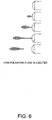
- FIG. 7 is an explanatory view showing sequence photographs of the moments of ejection of a pulsating flow.
- the case where the supply flow rate of the fluid is low, the case where the supply flow rate is proper, and the case where the supply flow rate is high are shown.
- the fluid in the fluid ejection tube 20 is extruded before the fluid ejection tube 20 is filled with the fluid. Therefore, the ejected pulsating flow is weak.
- the supply flow rate of the fluid is high, a continuous flow is generated immediately before a pulsating flow is generated, and a high-speed pulsating flow is generated after the continuous flow. Since the fluid in the fluid ejection tube 20 is extruded instantaneously, the speed of the pulsating flow is higher than the speed of the continuous flow.
- V 2 V 1 ⁇ 0.007
- the volume V2 of the fluid (streak-like droplet) ejected by the inertial effect of the fluid is approximately 0.007 times the elimination volume V1.
- the ratio of V1 to V2 varies depending on the configuration of the fluid ejection device 100 and the nature of the fluid. Therefore, it is preferable to set a proper ratio of V1 to V2 according to the configuration of the fluid ejection device 100 and the nature of the fluid.
- the fluid ejection device 100 is used as a medical apparatus.
- the fluid ejection device 100 may be used as another apparatus than the medical apparatus.
- the fluid ejection device 100 may be used as a cleaning device which ejects a fluid to a target object and thus removes stains from the target object, or a drawing device which draws letters and pictures with the ejected fluid.
- a liquid is used as a fluid ejected from the fluid ejection device 100.
- a gas may be used as a fluid ejected from the fluid ejection device 100.
- the magnitude of the drive voltage available to be set ranges from 0 V to 100 V and the frequency of the drive voltage available to be set ranges from 100 Hz to 400 Hz.
- the range of the magnitude of the drive voltage available to be set and the range of the frequency of the drive voltage available to be set may be different from the above ranges.
- the frequency of the drive voltage available to be set may range from 100 Hz to 1000 Hz.
- the elimination volume V1 is found as the product of the cross-sectional area of the fluid chamber 42 and the maximum displacement of the piezoelectric element 30.
- the elimination volume V1 is equal to the actual amount of change in the volume of the fluid chamber 42. Therefore, for example, when the piezoelectric element 30 expands to raise the internal pressure in the fluid chamber 42, it is preferable to consider the amount of contraction due to the elastic deformation of the piezoelectric element 30 under the pressure. It is also preferable to consider the shape of the diaphragm 32 when deformed. If the piezoelectric constant of the piezoelectric element 30 is known, the displacement of the piezoelectric element 30 may be found based on the piezoelectric constant and the drive voltage.
- the configuration in which the volume of the fluid chamber 42 decreases as the drive voltage applied to the piezoelectric element 30 increases is employed.
- a configuration in which the volume of the fluid chamber 42 increases as the drive voltage applied to the piezoelectric element 30 increases may be employed.
- condition switching unit 26 is provided on the handpiece 14.
- condition switching unit 26 may be provided at another position than on the handpiece 14.
- condition switching unit 26 may be provided in the controller 16.
- a piezoelectric element is used as the pulsation generator 22.
- an air bubble generator may be used as the pulsation generator.
- the air bubble generator for example, a heater, laser beam casting unit or the like may be used.
- any unit that heats the fluid in the fluid chamber and thus generates air bubbles so that the fluid in the fluid chamber is ejected by expansion of the generated air bubbles can be used.
- the controller controls the air bubble generator to generate air bubbles periodically. If the maximum frequency at which the controller causes the air bubble generator to generate air bubbles is fmax [Hz] and the amount of change in the volume of the fluid chamber in the case where a maximum amount of air bubbles is generated by the air bubble generator is V1 [ml], the fluid supplying unit may supply the fluid at the predetermined flow rate above Vlxfmax [ml/s].
- a part of the functions realized by software in the embodiment may be realized by hardware.
- a part of the functions realized by hardware may be realized by software.
Landscapes
- Health & Medical Sciences (AREA)
- Life Sciences & Earth Sciences (AREA)
- Surgery (AREA)
- Molecular Biology (AREA)
- General Health & Medical Sciences (AREA)
- Biomedical Technology (AREA)
- Heart & Thoracic Surgery (AREA)
- Medical Informatics (AREA)
- Nuclear Medicine, Radiotherapy & Molecular Imaging (AREA)
- Animal Behavior & Ethology (AREA)
- Engineering & Computer Science (AREA)
- Public Health (AREA)
- Veterinary Medicine (AREA)
- Surgical Instruments (AREA)
- Reciprocating Pumps (AREA)
- Details Of Reciprocating Pumps (AREA)
- Control Of Positive-Displacement Pumps (AREA)
Description
- The present invention relates to a fluid ejection device and a medical apparatus using the fluid ejection device.
- As a medical apparatus which ejects a fluid to a living tissue of a patient for treatment, for example, a device disclosed in
JP-A-2008-82202 JP-A-2008-82202 EP 2 286 745 A2 discloses a fluid ejection method including the steps of supplying fluid to a pressure chamber, generating a pulsed flow by varying the volume of the pressure chamber and ejecting the pulsed flow. - Since a fluid ejection device is used, for example, as a surgical knife, a stable sense of use is demanded of the fluid ejection device. There is also a demand that failure to eject a proper pulsating flow due to a shortage of a fluid supplied to the fluid ejection device should be restrained. Moreover, there is a demand that staying of a fluid at the affected part due to excess supply of the fluid to the fluid ejection device should be restrained.
- Also, a reduction in size, a reduction in cost, resource saving, easier manufacturing, improvement in usability and the like are demanded of the traditional fluid ejection devices.
- An advantage of some aspects of the invention is to solve at least a part of the problems described above.
- The invention provides a fluid ejection device according to
claim 1. Further embodiments of the invention are described in the dependent claims. This fluid ejection device includes: an ejection tube which ejects the fluid; a fluid chamber which communicates with the ejection tube; a fluid supplying unit which supplies the fluid to the fluid chamber at a predetermined flow rate; a pulsation generator which causes the fluid in the fluid chamber to be ejected from the ejection tube; and a controller which controls operation of the pulsation generator to cause the fluid to be ejected periodically from the ejection tube. If a maximum frequency at which the controller causes the fluid to be ejected is fmax [Hz] , and an amount of change in volume of the fluid chamber when the controller causes the pulsation generator to operate is V1 [ml], the fluid supplying unit supplies the fluid at the predetermined flow rate above V1×fmax [ml/s]. According to the fluid ejection device of this aspect, a shortage of the fluid in the fluid chamber when the pulsation generator is driven can be restrained, and the fluid is supplied at the predetermined flow rate. Therefore, the flow rate of the fluid ejected from the ejection tube is stable and a stable sense of use can be realized. - In the fluid ejection device described above, the fluid supplying unit may supply the fluid at the predetermined flow rate below V1×2.0×fmax [ml/s]. According to this fluid ejection device, excess supply of the fluid to the fluid chamber can be restrained.
- In the fluid ejection device described above, when the fluid in a volume V1 [ml] is ejected from the ejection tube by driving the pulsation generator once, if a volume of the fluid ejected from the ejection tube together with the fluid of the volume V1 [ml] by an inertial effect of the fluid is V2 [ml], the fluid supplying unit may supply the fluid at the predetermined flow rate equal to or above (V1+V2)×fmax [ml/s]. According to this fluid ejection device , the fluid can be supplied to the fluid chamber at a proper flow rate in consideration of the inertial effect of the fluid.
- In the fluid ejection device described above, the volume V2 may be V1×0.007. According to this fluid ejection device, the fluid can be supplied to the fluid chamber at a proper flow rate in consideration of the inertial effect of the fluid.
- Another embodiment of the invention provides a medical apparatus using the fluid ejection device of the aspect described above. According to this, a highly reliable medical apparatus can be provided.
- Not all of the plural components provided in this disclosure are essential. In order to solve a part or all of the foregoing problems, or in order to achieve a part or all of the advantages described herein, a part of the plural components can be properly changed, deleted, replaced with another new component, or partly deleted in a limited context.
- Specifically, the fluid supplying unit may be formed as a fluid supplying unit which supplies the fluid at the predetermined flow rate above Vlxfmax [ml/s], if the maximum frequency of the drive voltage is fmax [Hz] and the amount of change in the volume of the fluid chamber when the drive voltage of the maximum value is applied to a piezoelectric element to drive the piezoelectric element is V1 [ml]. Such a device can be realized, for example, as a fluid ejection device which ejects a fluid but can also be realized as another device but not only the fluid ejection device which ejects a fluid. According to such an aspect, at least one of the various problems such as a reduction in the size of the device, a reduction in cost, resource saving, easier manufacturing, and improvement in usability can be solved. A part of all of the technical features of each aspect of the foregoing fluid ejection device which ejects a fluid can be applied to this device.
- The invention will be described with reference to the accompanying drawings, wherein like numbers reference like elements.
-
FIG. 1 is an explanatory view showing the configuration of a fluid ejection device as an embodiment of the invention. -
FIG. 2 is an enlarged cross-sectional view showing a part of the inner configuration of a handpiece. -
FIG. 3 is an explanatory view showing an example of the waveform of a drive voltage applied to a piezoelectric element. -
FIG. 4 is an explanatory view showing the correspondence between the waveform of a drive voltage and how a diaphragm is deformed. -
FIGS. 5A and 5B are explanatory views schematically showing a change in the volume of a fluid chamber. -
FIG. 6 is an explanatory view schematically showing how a fluid of a volume exceeding an elimination volume is ejected from a fluid ejection tube. -
FIG. 7 is an explanatory view showing sequence photographs of the moment of ejection of a pulsating flow. - Hereinafter, embodiments of the invention will be described, in order of an embodiment, an experiment example, and modifications.
-
FIG. 1 is an explanatory view showing the configuration of afluid ejection device 100 as an embodiment of the invention. Thefluid ejection device 100 of this embodiment is a medical apparatus used in a medical institution and has the function of a surgical knife which ejects a fluid to a living tissue of an affected part of a patient and thereby performs treatment such as incision or excision of the affect part. - The
fluid ejection device 100 has afluid container 10, afluid supplying mechanism 12, ahandpiece 14, acontroller 16, and afoot switch 18. Thefluid container 10 and thefluid supplying mechanism 12 are connected to each other by aconnection tube 19a. Thefluid supplying mechanism 12 and thehandpiece 14 are connected to each other by aconnection tube 19b. In this embodiment, theconnection tubes - The
fluid container 10 houses a physiological saline solution as a fluid to be supplied to thehandpiece 14. However, thefluid container 10 may house another fluid that is harmless when ejected to a living tissue, for example, pure water, a drug solution or the like, instead of the physiological saline solution. - The
fluid supplying mechanism 12 supplies the fluid housed in thefluid container 10 to thehandpiece 14 via theconnection tubes fluid supplying mechanism 12. Also, in this embodiment, as will be described later, thefluid supplying mechanism 12 supplies the fluid to thehandpiece 14 at a predetermined flow rate. - The
handpiece 14 is an instrument which the operator holds in the hand and operates. Thehandpiece 14 has afluid ejection tube 20, apulsation generator 22, acasing 24, and acondition switching unit 26. A fluid is supplied to thepulsation generator 22 via theconnection tube 19b. When a drive voltage is applied to thepulsation generator 22 from thecontroller 16 via avoltage application cable 17a, thepulsation generator 22 generates pulsation in the supplied fluid. The fluid in which pulsation is generated is ejected at a high speed from an opening 20a at the forward end of thefluid ejection tube 20. The operator applies the fluid in which pulsation is generated and which is ejected from thehandpiece 14, to a living tissue of an affected part of a patient, thereby performing treatment such as incision or excision of the affected part. Hereinafter, the fluid in which pulsation is generated is also called a pulsating flow or pulse flow. - The
condition switching unit 26 is an operation unit for the operator to switch the magnitude and frequency of the drive voltage applied to thepulsation generator 22. In this embodiment, a dial-type selection unit is employed as thecondition switching unit 26, and the operator selects a magnitude and frequency of the drive voltage used for treatment, from predefined magnitudes and frequencies of the drive voltage. - As the magnitude of the drive voltage is changed, the magnitude and strength of the pulsating flow is changed. As the frequency of the drive voltage is changed, the frequency of generation of the pulsating flow is changed. In this embodiment, the magnitude of the drive voltage that is available to be set and the frequency of the drive voltage that is available to be set are as follows.
Magnitude of drive voltage available to be set: 0 V to 100 V Frequency of drive voltage available to be set: 100 Hz to 400 Hz - That it, in this embodiment, the maximum value available to be set Emax of the drive voltage is 100 V, and the maximum frequency available to be set fmax of the drive voltage is 400 Hz.
- The
controller 16 receives information about the magnitude and frequency of the drive voltage from thecondition switching unit 26 via acontrol cable 17b and applies the drive voltage that satisfies the condition designated by thecondition switching unit 26 to thepulsation generator 22 via thevoltage application cable 17a. Thecontroller 16 also controls the start and stop of thefluid supplying mechanism 12 via acontrol cable 17c. - The
foot switch 18 is a switch which the operator operates with the foot and is connected to thecontroller 16 via acontrol cable 17d. As the operator turns on thefoot switch 18, thecontroller 16 instructs thefluid supplying mechanism 12 to start supplying the fluid, and applies the drive voltage to thepulsation generator 22. Then, the fluid in which pulsation is generated is ejected at a high speed from theopening 20a at the forward end of thefluid ejection tube 20 of thehandpiece 14. -
FIG. 2 is an enlarged cross-sectional view showing a part of the inner configuration of thehandpiece 14. Inside thecasing 24 of thehandpiece 14, thepulsation generator 22 which generates pulsation in the fluid supplied from thefluid supplying mechanism 12 is provided. Thepulsation generator 22 has apiezoelectric element 30, adiaphragm 32, afirst case 34, asecond case 36, and athird case 38. - Inside the
pulsation generator 22, aninlet channel 40, afluid chamber 42, and anoutlet channel 44 are formed as a channel through which the fluid supplied from thefluid supplying mechanism 12 passes. In this embodiment, theinlet channel 40 and theoutlet channel 44 are formed in thefirst case 34. Thefluid chamber 42 is formed between thefirst case 34 and thediaphragm 32. Theconnection tube 19b is connected to theinlet channel 40. Thefluid ejection tube 20 is connected to theoutlet channel 44. - The
diaphragm 32 is a disc-shaped thin metal plate and an outer peripheral part thereof is held and fixed between thefirst case 34 and thesecond case 36. - The
piezoelectric element 30 is an actuator which operates on receiving the drive voltage applied from thecontroller 16. Thepiezoelectric element 30 changes the volume of thefluid chamber 42 formed between thediaphragm 32 and thefirst case 34, thereby changing the pressure of the fluid in thefluid chamber 42. In this embodiment, thepiezoelectric element 30 is a multilayer piezoelectric element, with one end thereof fixed to thediaphragm 32 and the other end thereof fixed to thethird case 38. - When the drive voltage applied to the
piezoelectric element 30 increases, thepiezoelectric element 30 expands. Thediaphragm 32 is pushed by thepiezoelectric element 30 and flexes toward thefluid chamber 42. As thediaphragm 32 flexes toward thefluid chamber 42, the volume of thefluid chamber 42 decreases and the fluid in thefluid chamber 42 is extruded from thefluid chamber 42. In this embodiment, the inner diameter of theoutlet channel 44 is greater than the inner diameter of theinlet channel 40. That is, since the inertance of theoutlet channel 44 is smaller than the inertance of theinlet channel 40, the fluid in thefluid chamber 42 is extruded from thefluid chamber 42 through theoutlet channel 44. - Meanwhile, when the drive voltage applied to the
piezoelectric element 30 decreases, thepiezoelectric element 30 contracts and the volume of thefluid chamber 42 increases. Thus, the fluid is supplied into thefluid chamber 42 from theinlet channel 40. - Since the drive voltage applied to the
piezoelectric element 30 repeats on-state (maximum voltage) and off-state (0 V) at a high frequency (for example, 400 Hz), an increase and decrease in the volume of thefluid chamber 42 is repeated, thus generating pulsation in the fluid. The fluid extruded from thefluid chamber 42 is ejected from thenozzle 20a (opening 20a) at the forward end of thefluid ejection tube 20. -
FIG. 3 is an explanatory view showing an example of the waveform of the drive voltage applied to thepiezoelectric element 30. InFIG. 3 , the horizontal axis represents time and the vertical axis represents drive voltage. One cycle of the waveform of the drive voltage includes a rising period during which the voltage increases, a falling period during which the voltage decreases, and a suspension period during which no voltage is applied. - In this embodiment, the waveform in the rising period of the drive voltage is a
SIN waveform 1/2-cycle waveform that is offset in the direction of positive voltage, with the phase thereof shifted by -90 degrees. The waveform in the falling period of the drive voltage is aSIN waveform 1/2-cycle waveform that is offset in the direction of positive voltage, with the phase thereof shifted by +90 degrees. The cycle of the SIN waveform in the falling period is greater than the cycle of the SIN waveform in the rising period. - In this embodiment, when the magnitude of the drive voltage is changed by the
condition switching unit 26, the maximum value of the waveform shown inFIG. 3 is changed. Meanwhile, when the frequency of the drive voltage is changed by thecondition switching unit 26, the waveforms in the rising period and the falling period are not changed and the length of the suspension period is changed. -
FIG. 4 is an explanatory view showing the correspondence between the waveform of the drive voltage and how thediaphragm 32 is deformed. InFIG. 4 , a reinforcingmember 51 is provided between thepiezoelectric element 30 and thediaphragm 32. During the suspension period (a), since no drive voltage is applied, thepiezoelectric element 30 does not expand and thediaphragm 32 does not flex. During the rising period (b), since the drive voltage increases, thepiezoelectric element 30 expands and thediaphragm 32 flexes toward thefluid chamber 42. The volume of thefluid chamber 42 decreases. - At the timing (c), since the drive voltage reaches the maximum, the length of the
piezoelectric element 30 reaches the maximum and the volume of thefluid chamber 42 reaches the minimum. During the falling period (d), since the drive voltage decreases, thepiezoelectric element 30 begins to restore the original size and the volume of thefluid chamber 42 begins to restore the original size. During the suspension period (e), since no drive voltage is applied, thepiezoelectric element 30 restores the original size and the volume of thefluid chamber 42 restores the original size. As this series of operations shown by (a) to (e) is repeated, the fluid in thefluid chamber 42 is extruded to thefluid ejection tube 20. -
FIGS. 5A and 5B are explanatory views schematically showing a change in the volume of thefluid chamber 42.FIG. 5A shows the state where no drive voltage is applied to thepiezoelectric element 30 and the volume of thefluid chamber 42 is at its maximum.FIG. 5B shows the state where the drive voltage applied to thepiezoelectric element 30 is at its maximum and the volume of thefluid chamber 42 is at its minimum. A hatched area R inFIG. 5B represents the volume of thefluid chamber 42 changing during one cycle of the drive voltage. That is, the.area R represents the volume of the fluid eliminated from thefluid chamber 42 during one cycle of the drive voltage. In this description, the volume of the fluid eliminated from thefluid chamber 42 during one cycle of the drive voltage is called an elimination volume. In the schematic views ofFIGS. 5A and 5B , the elimination volume is found as the product of the cross-sectional area of thefluid chamber 42 and the length by which thepiezoelectric element 30 is expanded. - In this embodiment, the elimination volume in the case where the
piezoelectric element 30 is driven by a maximum drive voltage Emax available to be set by thecondition switching unit 26 is defined as V1 [ml]. The maximum frequency available to be set by thecondition switching unit 26 is defined as fmax [Hz]. Thus, when thepiezoelectric element 30 is driven with the maximum drive voltage Emax and the maximum frequency fmax, the volume Vf [ml] of the fluid extruded from thefluid chamber 42 in one second is found as follows.
- However, in practice, a greater amount of the fluid than the elimination volume V1 is ejected from the
fluid ejection tube 20 as a pulsating flow during one cycle of the drive voltage. Hereinafter, this phenomenon will be described. -
FIG. 6 is an explanatory view schematically showing how the fluid of an amount exceeding the elimination volume V1 is ejected from thefluid ejection tube 20. As shown inFIG. 6 , as thepiezoelectric element 30 is driven and a droplet-like pulsating flow is ejected from thefluid ejection tube 20, a streak-like droplet is ejected from thefluid ejection tube 20, continuing to the ejected droplet. This is because the inertial effect of the fluid causes the fluid in thefluid ejection tube 20 to be pulled by the ejected droplet. As a result, when thepiezoelectric element 30 is driven with the maximum drive voltage Emax and the maximum frequency fmax, the fluid in the volume exceeding the elimination volume V1 is ejected from thefluid ejection tube 20 as a pulsating flow. - Therefore, in the case where the
fluid supplying mechanism 12 supplies the fluid to thefluid chamber 42 at the flow rate of Vf [ml/s] and thepiezoelectric element 30 is driven with the maximum drive voltage Emax and the maximum frequency fmax, a shortage of the fluid occurs and therefore a proper pulsating flow cannot be ejected. - Thus, in this embodiment, the
fluid supplying mechanism 12 supplies the fluid at a predetermined flow rate above Vf [ml/s]. As a result, a shortage of the fluid can be restrained even in the case where thepiezoelectric element 30 is driven with the maximum drive voltage Emax and the maximum frequency fmax. - Specifically, when the fluid in the volume of V1 [ml] is extruded from the
fluid chamber 42 by driving thepiezoelectric element 30 once, the volume of the fluid (streak-like droplet) ejected together with the fluid (droplet) in the volume of V1 [ml] by the inertial effect of the fluid is defined as V2 [ml]. In this case, thefluid supplying mechanism 12 of this embodiment supplies the fluid at a predetermined flow rate above (V1+V2)×fmax [ml/s]. Thus, the fluid can be supplied to thefluid chamber 42 at a proper flow rate in consideration of the fluid ejected by the inertial effect of the fluid, and therefore a shortage of the fluid can be restrained. - Moreover, in this embodiment, the fluid is supplied at a predetermined flow rate above Vf [ml/s], even if the magnitude and frequency of the drive voltage is changed by the
condition switching unit 26. Therefore, since the predetermined flow rate of the fluid ejected from thefluid ejection tube 20 is maintained even if the drive voltage is low or even if the frequency of the drive voltage is low, the operator using thefluid ejection device 100 can experience a stable sense of use. If the drive voltage is changed to a lower value or to a lower frequency, the excess fluid that is supplied is discharged from thefluid ejection tube 20 as a continuous flow without pulsation. - It is confirmed that the volume V2 of the fluid (streak-like droplet) ejected by the inertial effect of the fluid is smaller than the elimination volume V1. Therefore, the volume of the fluid (V1+V2) ejected as a pulsating flow by driving the
piezoelectric element 30 once is smaller than V1×2.0. Thus, thefluid supplying mechanism 12 of this embodiment supplies the fluid to thefluid chamber 42 at a predetermined flow rate below V1×2.0×fmax [ml/s]. Therefore, according to this embodiment, since excess supply of the fluid to thefluid chamber 42 can be restrained, excess discharge of a continuous flow without pulsation from thefluid ejection tube 20 can be restrained. As a result, the amount of the fluid used can be reduced and the amount of the fluid remaining on a treatment target can be reduced. Thus, a good operating field can be secured. - In this way, according to this embodiment, since the fluid is supplied at a predetermined flow rate above Vf [ml/s], even in the case where the
piezoelectric element 30 is driven with the maximum drive voltage Emax and the maximum frequency fmax, a shortage of the fluid in thefluid chamber 42 can be restrained and the operator using thefluid ejection device 100 can experience a stable sense of use. - In the actual
fluid supplying mechanism 12, even in the case of supplying the fluid at a "predetermined" flow rate, it may be difficult to maintain the predetermined flow rate strictly and a variance of ±10% may occur. Therefore, the term "predetermined" used herein includes cases where a variance of ±10% occurs. Even in the case where thefluid supplying mechanism 12 is a roller pump, plunger pump or the like and has an instantaneous variance in the flow rate, the effect of the invention is hardly impaired as long as the average flow rate in a macroscopic time cycle is a predetermined flow rate. - In this experiment example, a pulsating flow ejected from the
fluid ejection tube 20 is observed while the supply flow rate of the fluid by thefluid supplying mechanism 12 is changed. Thus, a proper supply flow rate of the fluid is found. Then, how large the volume V2 of the fluid (streak-like droplet) ejected by the inertial effect of the fluid is, relative to the elimination volume V1, is examined. The state where the supply flow rate of the fluid is proper refers to the state where a proper pulsating flow is ejected and an unnecessary continuous flow does not occur between pulsating flows. The reason why a continuous flow is not necessary is because a continuous flow is extruded simply by the pressure from thefluid supplying mechanism 12 and therefore hardly contributes to incision, excision or the like of an affected part. Moreover, the occurrence of a continuous flow causes an increase of the fluid remaining at the affected part and therefore narrows the operating field. - The conditions in this experiment example are as follows.
Maximum drive voltage Emax: 100 V Maximum frequency fmax: 400 Hz Maximum displacement of piezoelectric element when maximum drive voltage Emax is applied: 10 µm Diameter of fluid chamber: 6 mm Cross-sectional area of fluid chamber: 2.83×10⁻⁵ m2 - According to the above conditions, the elimination volume V1 is found as follows.

- The elimination volume per minute is expressed by the following equation (1).

-
FIG. 7 is an explanatory view showing sequence photographs of the moments of ejection of a pulsating flow. InFIG. 7 , the case where the supply flow rate of the fluid is low, the case where the supply flow rate is proper, and the case where the supply flow rate is high are shown. As shown inFIG. 7 , in the case where the supply flow rate of the fluid is low, the fluid in thefluid ejection tube 20 is extruded before thefluid ejection tube 20 is filled with the fluid. Therefore, the ejected pulsating flow is weak. Meanwhile, in the case where the supply flow rate of the fluid is high, a continuous flow is generated immediately before a pulsating flow is generated, and a high-speed pulsating flow is generated after the continuous flow. Since the fluid in thefluid ejection tube 20 is extruded instantaneously, the speed of the pulsating flow is higher than the speed of the continuous flow. - In the case where the supply flow rate of the fluid is proper, no unnecessary continuous flow is generated and a pulsating flow is generated intermittently. Specifically, after the
fluid ejection tube 20 is filled with the fluid, the fluid in thefluid ejection tube 20 is extruded instantaneously, generating a pulsating flow with great strength. While thefluid ejection tube 20 is filled with the fluid again, no unnecessary continuous flow is generated. After thefluid ejection tube 20 is filled with the fluid, a pulsating flow is generated again. - As a result of the above experiment, the proper supply flow rate of the fluid is found to be 6.84 ml/minute. Therefore, the following equation (2) holds.

- Subtracting the equation (1) from the equation (2) results in the following equation (3).

- Based on the equations (1) and (3), the relation between V2 and V1 can be derived as expressed by the following equation (4).

- According to the above calculations, under the conditions of this experiment example, the volume V2 of the fluid (streak-like droplet) ejected by the inertial effect of the fluid is approximately 0.007 times the elimination volume V1. However, the ratio of V1 to V2 varies depending on the configuration of the
fluid ejection device 100 and the nature of the fluid. Therefore, it is preferable to set a proper ratio of V1 to V2 according to the configuration of thefluid ejection device 100 and the nature of the fluid. - The invention is not limited to the above embodiment and experiment example and can be carried out in various forms without departing from the scope of the invention. For example, the following modifications can be made.
- In the embodiment, the
fluid ejection device 100 is used as a medical apparatus. However, as a modification, thefluid ejection device 100 may be used as another apparatus than the medical apparatus. For example, thefluid ejection device 100 may be used as a cleaning device which ejects a fluid to a target object and thus removes stains from the target object, or a drawing device which draws letters and pictures with the ejected fluid. - In the embodiment, a liquid is used as a fluid ejected from the
fluid ejection device 100. However, as a modification, a gas may be used as a fluid ejected from thefluid ejection device 100. - In the embodiment, the magnitude of the drive voltage available to be set ranges from 0 V to 100 V and the frequency of the drive voltage available to be set ranges from 100 Hz to 400 Hz. However, as a modification, the range of the magnitude of the drive voltage available to be set and the range of the frequency of the drive voltage available to be set may be different from the above ranges. For example, the frequency of the drive voltage available to be set may range from 100 Hz to 1000 Hz.
- In the embodiment, the elimination volume V1 is found as the product of the cross-sectional area of the
fluid chamber 42 and the maximum displacement of thepiezoelectric element 30. However, strictly speaking, it is preferable that the elimination volume V1 is equal to the actual amount of change in the volume of thefluid chamber 42. Therefore, for example, when thepiezoelectric element 30 expands to raise the internal pressure in thefluid chamber 42, it is preferable to consider the amount of contraction due to the elastic deformation of thepiezoelectric element 30 under the pressure. It is also preferable to consider the shape of thediaphragm 32 when deformed. If the piezoelectric constant of thepiezoelectric element 30 is known, the displacement of thepiezoelectric element 30 may be found based on the piezoelectric constant and the drive voltage. - In the embodiment, the configuration in which the volume of the
fluid chamber 42 decreases as the drive voltage applied to thepiezoelectric element 30 increases is employed. However, as a modification, a configuration in which the volume of thefluid chamber 42 increases as the drive voltage applied to thepiezoelectric element 30 increases may be employed. - In the embodiment, the
condition switching unit 26 is provided on thehandpiece 14. However, as a modification, thecondition switching unit 26 may be provided at another position than on thehandpiece 14. For example, thecondition switching unit 26 may be provided in thecontroller 16. - In the embodiment, a piezoelectric element is used as the
pulsation generator 22. However, as a modification 7, an air bubble generator may be used as the pulsation generator. As the air bubble generator, for example, a heater, laser beam casting unit or the like may be used. As the air bubble generator, any unit that heats the fluid in the fluid chamber and thus generates air bubbles so that the fluid in the fluid chamber is ejected by expansion of the generated air bubbles can be used. - In such a case, the controller controls the air bubble generator to generate air bubbles periodically. If the maximum frequency at which the controller causes the air bubble generator to generate air bubbles is fmax [Hz] and the amount of change in the volume of the fluid chamber in the case where a maximum amount of air bubbles is generated by the air bubble generator is V1 [ml], the fluid supplying unit may supply the fluid at the predetermined flow rate above Vlxfmax [ml/s].
- A part of the functions realized by software in the embodiment may be realized by hardware. Alternatively, a part of the functions realized by hardware may be realized by software.
- The invention is not limited to the above embodiment, example and modifications and can be realized in various configurations without departing from the scope of the invention.
- Also, the technical features can be suitably deleted unless these features are described as essential herein.
Claims (8)
- A fluid ejection device (100) which ejects a fluid, comprising:an ejection tube (20) which ejects the fluid;a fluid chamber (42) which communicates with the ejection tube (20);a fluid supplying unit (12) which supplies the fluid to the fluid chamber at a predetermined flow rate;a pulsation generator (22) which causes the fluid in the fluid chamber (42) to be ejected from the ejection tube (20) ;a controller (16) which controls operation of the pulsation generator (22) to cause the fluid to be ejected periodically from the ejection tube (20),
characterized in thatif a maximum frequency at which the controller (16) causes the fluid to be ejected is fmax [Hz], andan amount of change in volume of the fluid chamber (42) when the controller (16) causes the pulsation generator (22) to operate by applying a maximum value of a drive voltage is V1 [ml],the fluid supplying unit (12) is configured to supply the fluid at the predetermined flow rate above V1×fmax [ml/s], such that the predetermined flow rate is maintained even if the drive voltage is lower than the maximum value or even if the frequency of the drive voltage is lower than the maximum frequency. - The fluid ejection device (100) according to claim 1, wherein the fluid supplying unit (12) supplies the fluid at the predetermined flow rate below V1×2.0×fmax [ml/s].
- The fluid ejection device (100) according to claim 1 or 2, wherein when the fluid in a volume V1 [ml] is ejected from the ejection tube (20) by driving the pulsation generator (22) once, if a volume of the fluid ejected from the ejection tube (20) together with the fluid of the volume V1 [ml] by an inertial effect of the fluid is V2 [ml],
the fluid supplying unit (12) supplies the fluid at the predetermined flow rate equal to or above (V1+V2)×fmax [ml/s] . - The fluid ejection device (100) according to claim 3, wherein the volume V2 is V1×0.007.
- A medical apparatus using the fluid ejection device (100) according to any one of claims 1 to 4.
- A medical apparatus using the fluid ejection device (100) according to claim 2.
- A medical apparatus using the fluid ejection device (100) according to claim 3.
- A medical apparatus using the fluid ejection device (100) according to claim 4.
Applications Claiming Priority (1)
| Application Number | Priority Date | Filing Date | Title |
|---|---|---|---|
| JP2013067718A JP6186798B2 (en) | 2013-03-28 | 2013-03-28 | Fluid ejecting apparatus and medical device |
Publications (2)
| Publication Number | Publication Date |
|---|---|
| EP2783645A1 EP2783645A1 (en) | 2014-10-01 |
| EP2783645B1 true EP2783645B1 (en) | 2016-09-14 |
Family
ID=50382335
Family Applications (1)
| Application Number | Title | Priority Date | Filing Date |
|---|---|---|---|
| EP14161974.2A Active EP2783645B1 (en) | 2013-03-28 | 2014-03-27 | Fluid ejection device and medical apparatus |
Country Status (4)
| Country | Link |
|---|---|
| US (1) | US9737327B2 (en) |
| EP (1) | EP2783645B1 (en) |
| JP (1) | JP6186798B2 (en) |
| CN (1) | CN104068914A (en) |
Families Citing this family (7)
| Publication number | Priority date | Publication date | Assignee | Title |
|---|---|---|---|---|
| JP2015058240A (en) * | 2013-09-20 | 2015-03-30 | セイコーエプソン株式会社 | Medical device system and liquid supply device |
| JP2016027838A (en) * | 2014-07-11 | 2016-02-25 | セイコーエプソン株式会社 | Liquid injection control device, liquid injection system, and control method |
| JP2016120023A (en) * | 2014-12-24 | 2016-07-07 | セイコーエプソン株式会社 | Liquid injection control device, and liquid injection system and control method |
| JP2016120024A (en) * | 2014-12-24 | 2016-07-07 | セイコーエプソン株式会社 | Liquid injection control device, and liquid injection system and control method |
| WO2021080567A1 (en) * | 2019-10-22 | 2021-04-29 | Hewlett-Packard Development Company, L.P. | Fluidic die with a suppressible clock circuit |
| JP7443845B2 (en) * | 2020-03-16 | 2024-03-06 | セイコーエプソン株式会社 | liquid injection device |
| CN113649238B (en) * | 2021-09-06 | 2022-08-30 | 业成科技(成都)有限公司 | Fluid control device and dispensing device thereof |
Family Cites Families (26)
| Publication number | Priority date | Publication date | Assignee | Title |
|---|---|---|---|---|
| CN2119203U (en) * | 1992-04-15 | 1992-10-21 | 第二汽车制造厂 | Double-orifice water jet cutting scalpel and device |
| JPH06277283A (en) | 1993-03-30 | 1994-10-04 | Sharp Corp | Infusion device |
| JP4703083B2 (en) | 2000-01-21 | 2011-06-15 | メドトロニック ミニメド インコーポレイテッド | Medical system |
| US6589229B1 (en) | 2000-07-31 | 2003-07-08 | Becton, Dickinson And Company | Wearable, self-contained drug infusion device |
| JP2003071448A (en) | 2001-08-31 | 2003-03-11 | Mikuni Corp | Electrolytic water maker |
| JP2003180826A (en) | 2001-12-17 | 2003-07-02 | Terumo Corp | Medicinal liquid infusion apparatus |
| JP2003180827A (en) | 2001-12-17 | 2003-07-02 | Terumo Corp | Medicinal liquid infusion apparatus |
| JP4095374B2 (en) | 2002-08-27 | 2008-06-04 | ペンタックス株式会社 | Endoscope water supply device |
| JP2004309163A (en) | 2003-04-02 | 2004-11-04 | Yaskawa Electric Corp | Liquid feeding module, liquid feeding apparatus, and driving method therefor |
| JP4367086B2 (en) * | 2003-10-24 | 2009-11-18 | セイコーエプソン株式会社 | Pump drive method |
| JP4444640B2 (en) | 2003-12-15 | 2010-03-31 | 川澄化学工業株式会社 | Infusion pump device |
| JP2005192807A (en) | 2004-01-07 | 2005-07-21 | Cyber Firm Inc | Somatic condition regulating system |
| JP2006136376A (en) | 2004-11-10 | 2006-06-01 | K & Y:Kk | Disposable infusion device system |
| JP5082049B2 (en) | 2006-09-26 | 2012-11-28 | セイコーエプソン株式会社 | Fluid ejecting apparatus and surgical tool |
| JP4933911B2 (en) | 2007-02-02 | 2012-05-16 | 学校法人日本医科大学 | Ultrasound surgical device |
| JP5115088B2 (en) | 2007-08-10 | 2013-01-09 | セイコーエプソン株式会社 | Surgical tool |
| JP2009055958A (en) | 2007-08-30 | 2009-03-19 | Terumo Corp | Medical solution cartridge and medical solution injection device using the same |
| JP2009078041A (en) | 2007-09-27 | 2009-04-16 | Terumo Corp | Medical solution cartridge and medical solution injection device using the same |
| JP2010051430A (en) * | 2008-08-27 | 2010-03-11 | Seiko Epson Corp | Pulse generating mechanism, connection flow channel tube, fluid ejection apparatus |
| JP5293031B2 (en) * | 2008-09-16 | 2013-09-18 | セイコーエプソン株式会社 | Fluid ejecting apparatus and surgical instrument |
| JP4788809B2 (en) * | 2009-08-17 | 2011-10-05 | セイコーエプソン株式会社 | Fluid injection method |
| JP2011143145A (en) * | 2010-01-18 | 2011-07-28 | Seiko Epson Corp | Liquid-jet device |
| JP2011160868A (en) | 2010-02-05 | 2011-08-25 | Ricoh Co Ltd | Flow rate control apparatus and pump apparatus |
| JP2011177411A (en) | 2010-03-03 | 2011-09-15 | Ricoh Co Ltd | Infusion volume adjusting device, method for adjusting infusion volume, infusion system, and program |
| JP2012035101A (en) | 2011-10-17 | 2012-02-23 | Nippon Medical School | Ultrasonic surgical instrument |
| JP5408324B2 (en) | 2012-10-15 | 2014-02-05 | セイコーエプソン株式会社 | Fluid ejecting apparatus and medical device |
-
2013
- 2013-03-28 JP JP2013067718A patent/JP6186798B2/en active Active
-
2014
- 2014-03-27 EP EP14161974.2A patent/EP2783645B1/en active Active
- 2014-03-27 US US14/227,374 patent/US9737327B2/en active Active
- 2014-03-27 CN CN201410120713.1A patent/CN104068914A/en active Pending
Also Published As
| Publication number | Publication date |
|---|---|
| JP2014190279A (en) | 2014-10-06 |
| US9737327B2 (en) | 2017-08-22 |
| US20140296895A1 (en) | 2014-10-02 |
| EP2783645A1 (en) | 2014-10-01 |
| CN104068914A (en) | 2014-10-01 |
| JP6186798B2 (en) | 2017-08-30 |
Similar Documents
| Publication | Publication Date | Title |
|---|---|---|
| EP2783645B1 (en) | Fluid ejection device and medical apparatus | |
| US9289228B2 (en) | Fluid injection device | |
| JP4666094B2 (en) | PULSE FLOW GENERATION DEVICE, MEDICAL DEVICE, AND METHOD OF CONTROLLING PULSE FLOW GENERATION DEVICE | |
| JP5636811B2 (en) | Liquid ejecting apparatus and medical device using liquid ejecting apparatus | |
| EP2491875A2 (en) | Fluid ejection device | |
| JP2010106748A (en) | Fluid ejection system, method for driving fluid ejection system, and surgical apparatus | |
| EP2783644A1 (en) | Fluid ejection device and medical apparatus | |
| JP2009045167A (en) | Fluid injection apparatus | |
| JP6044098B2 (en) | Liquid ejecting apparatus and method for controlling liquid ejecting apparatus | |
| US9234516B2 (en) | Fluid ejection device and medical device | |
| EP3037048A1 (en) | Liquid ejection control device, liquid ejection system, and control method | |
| EP3037046A1 (en) | Liquid ejection control device, liquid ejection system, and control method | |
| JP2010059939A (en) | Fluid injection device, method of controlling fluid injection device, and surgical device | |
| US20150073453A1 (en) | Medical device | |
| JP2010077949A (en) | Fluid injection device, method for molding pipe member, fluid injection unit, and surgical apparatus | |
| JP2018086041A (en) | Liquid injection device | |
| JP2011017342A (en) | Pulsating flow generating apparatus, medical equipment and method of controlling the pulsating flow generating apparatus | |
| JP2012152423A (en) | Fluid injection device and control method thereof, and surgical device | |
| JP2018114108A (en) | Liquid feeding device and medical equipment | |
| JP2015016360A (en) | Fluid jetting device and surgery device | |
| JP2014184315A (en) | Block of injection unit for liquid injection device, injection unit for liquid injection device, and surgical instrument |
Legal Events
| Date | Code | Title | Description |
|---|---|---|---|
| 17P | Request for examination filed |
Effective date: 20140327 |
|
| AK | Designated contracting states |
Kind code of ref document: A1 Designated state(s): AL AT BE BG CH CY CZ DE DK EE ES FI FR GB GR HR HU IE IS IT LI LT LU LV MC MK MT NL NO PL PT RO RS SE SI SK SM TR |
|
| AX | Request for extension of the european patent |
Extension state: BA ME |
|
| PUAI | Public reference made under article 153(3) epc to a published international application that has entered the european phase |
Free format text: ORIGINAL CODE: 0009012 |
|
| R17P | Request for examination filed (corrected) |
Effective date: 20150305 |
|
| RBV | Designated contracting states (corrected) |
Designated state(s): AL AT BE BG CH CY CZ DE DK EE ES FI FR GB GR HR HU IE IS IT LI LT LU LV MC MK MT NL NO PL PT RO RS SE SI SK SM TR |
|
| 17Q | First examination report despatched |
Effective date: 20150811 |
|
| GRAP | Despatch of communication of intention to grant a patent |
Free format text: ORIGINAL CODE: EPIDOSNIGR1 |
|
| RIC1 | Information provided on ipc code assigned before grant |
Ipc: A61B 17/3203 20060101AFI20160209BHEP |
|
| INTG | Intention to grant announced |
Effective date: 20160307 |
|
| RAP1 | Party data changed (applicant data changed or rights of an application transferred) |
Owner name: SEIKO EPSON CORPORATION |
|
| GRAS | Grant fee paid |
Free format text: ORIGINAL CODE: EPIDOSNIGR3 |
|
| GRAA | (expected) grant |
Free format text: ORIGINAL CODE: 0009210 |
|
| RAP1 | Party data changed (applicant data changed or rights of an application transferred) |
Owner name: SEIKO EPSON CORPORATION |
|
| AK | Designated contracting states |
Kind code of ref document: B1 Designated state(s): AL AT BE BG CH CY CZ DE DK EE ES FI FR GB GR HR HU IE IS IT LI LT LU LV MC MK MT NL NO PL PT RO RS SE SI SK SM TR |
|
| REG | Reference to a national code |
Ref country code: GB Ref legal event code: FG4D |
|
| REG | Reference to a national code |
Ref country code: CH Ref legal event code: EP |
|
| REG | Reference to a national code |
Ref country code: IE Ref legal event code: FG4D |
|
| REG | Reference to a national code |
Ref country code: AT Ref legal event code: REF Ref document number: 828036 Country of ref document: AT Kind code of ref document: T Effective date: 20161015 |
|
| REG | Reference to a national code |
Ref country code: DE Ref legal event code: R096 Ref document number: 602014003569 Country of ref document: DE |
|
| REG | Reference to a national code |
Ref country code: LT Ref legal event code: MG4D |
|
| REG | Reference to a national code |
Ref country code: NL Ref legal event code: MP Effective date: 20160914 |
|
| PG25 | Lapsed in a contracting state [announced via postgrant information from national office to epo] |
Ref country code: FI Free format text: LAPSE BECAUSE OF FAILURE TO SUBMIT A TRANSLATION OF THE DESCRIPTION OR TO PAY THE FEE WITHIN THE PRESCRIBED TIME-LIMIT Effective date: 20160914 Ref country code: LT Free format text: LAPSE BECAUSE OF FAILURE TO SUBMIT A TRANSLATION OF THE DESCRIPTION OR TO PAY THE FEE WITHIN THE PRESCRIBED TIME-LIMIT Effective date: 20160914 Ref country code: HR Free format text: LAPSE BECAUSE OF FAILURE TO SUBMIT A TRANSLATION OF THE DESCRIPTION OR TO PAY THE FEE WITHIN THE PRESCRIBED TIME-LIMIT Effective date: 20160914 Ref country code: NO Free format text: LAPSE BECAUSE OF FAILURE TO SUBMIT A TRANSLATION OF THE DESCRIPTION OR TO PAY THE FEE WITHIN THE PRESCRIBED TIME-LIMIT Effective date: 20161214 Ref country code: RS Free format text: LAPSE BECAUSE OF FAILURE TO SUBMIT A TRANSLATION OF THE DESCRIPTION OR TO PAY THE FEE WITHIN THE PRESCRIBED TIME-LIMIT Effective date: 20160914 |
|
| REG | Reference to a national code |
Ref country code: AT Ref legal event code: MK05 Ref document number: 828036 Country of ref document: AT Kind code of ref document: T Effective date: 20160914 |
|
| PG25 | Lapsed in a contracting state [announced via postgrant information from national office to epo] |
Ref country code: GR Free format text: LAPSE BECAUSE OF FAILURE TO SUBMIT A TRANSLATION OF THE DESCRIPTION OR TO PAY THE FEE WITHIN THE PRESCRIBED TIME-LIMIT Effective date: 20161215 Ref country code: SE Free format text: LAPSE BECAUSE OF FAILURE TO SUBMIT A TRANSLATION OF THE DESCRIPTION OR TO PAY THE FEE WITHIN THE PRESCRIBED TIME-LIMIT Effective date: 20160914 Ref country code: NL Free format text: LAPSE BECAUSE OF FAILURE TO SUBMIT A TRANSLATION OF THE DESCRIPTION OR TO PAY THE FEE WITHIN THE PRESCRIBED TIME-LIMIT Effective date: 20160914 Ref country code: LV Free format text: LAPSE BECAUSE OF FAILURE TO SUBMIT A TRANSLATION OF THE DESCRIPTION OR TO PAY THE FEE WITHIN THE PRESCRIBED TIME-LIMIT Effective date: 20160914 |
|
| REG | Reference to a national code |
Ref country code: FR Ref legal event code: PLFP Year of fee payment: 4 |
|
| PG25 | Lapsed in a contracting state [announced via postgrant information from national office to epo] |
Ref country code: RO Free format text: LAPSE BECAUSE OF FAILURE TO SUBMIT A TRANSLATION OF THE DESCRIPTION OR TO PAY THE FEE WITHIN THE PRESCRIBED TIME-LIMIT Effective date: 20160914 Ref country code: EE Free format text: LAPSE BECAUSE OF FAILURE TO SUBMIT A TRANSLATION OF THE DESCRIPTION OR TO PAY THE FEE WITHIN THE PRESCRIBED TIME-LIMIT Effective date: 20160914 |
|
| PG25 | Lapsed in a contracting state [announced via postgrant information from national office to epo] |
Ref country code: PL Free format text: LAPSE BECAUSE OF FAILURE TO SUBMIT A TRANSLATION OF THE DESCRIPTION OR TO PAY THE FEE WITHIN THE PRESCRIBED TIME-LIMIT Effective date: 20160914 Ref country code: ES Free format text: LAPSE BECAUSE OF FAILURE TO SUBMIT A TRANSLATION OF THE DESCRIPTION OR TO PAY THE FEE WITHIN THE PRESCRIBED TIME-LIMIT Effective date: 20160914 Ref country code: IS Free format text: LAPSE BECAUSE OF FAILURE TO SUBMIT A TRANSLATION OF THE DESCRIPTION OR TO PAY THE FEE WITHIN THE PRESCRIBED TIME-LIMIT Effective date: 20170114 Ref country code: SK Free format text: LAPSE BECAUSE OF FAILURE TO SUBMIT A TRANSLATION OF THE DESCRIPTION OR TO PAY THE FEE WITHIN THE PRESCRIBED TIME-LIMIT Effective date: 20160914 Ref country code: PT Free format text: LAPSE BECAUSE OF FAILURE TO SUBMIT A TRANSLATION OF THE DESCRIPTION OR TO PAY THE FEE WITHIN THE PRESCRIBED TIME-LIMIT Effective date: 20170116 Ref country code: BE Free format text: LAPSE BECAUSE OF FAILURE TO SUBMIT A TRANSLATION OF THE DESCRIPTION OR TO PAY THE FEE WITHIN THE PRESCRIBED TIME-LIMIT Effective date: 20160914 Ref country code: SM Free format text: LAPSE BECAUSE OF FAILURE TO SUBMIT A TRANSLATION OF THE DESCRIPTION OR TO PAY THE FEE WITHIN THE PRESCRIBED TIME-LIMIT Effective date: 20160914 Ref country code: BG Free format text: LAPSE BECAUSE OF FAILURE TO SUBMIT A TRANSLATION OF THE DESCRIPTION OR TO PAY THE FEE WITHIN THE PRESCRIBED TIME-LIMIT Effective date: 20161214 Ref country code: AT Free format text: LAPSE BECAUSE OF FAILURE TO SUBMIT A TRANSLATION OF THE DESCRIPTION OR TO PAY THE FEE WITHIN THE PRESCRIBED TIME-LIMIT Effective date: 20160914 Ref country code: CZ Free format text: LAPSE BECAUSE OF FAILURE TO SUBMIT A TRANSLATION OF THE DESCRIPTION OR TO PAY THE FEE WITHIN THE PRESCRIBED TIME-LIMIT Effective date: 20160914 |
|
| REG | Reference to a national code |
Ref country code: DE Ref legal event code: R097 Ref document number: 602014003569 Country of ref document: DE |
|
| PG25 | Lapsed in a contracting state [announced via postgrant information from national office to epo] |
Ref country code: IT Free format text: LAPSE BECAUSE OF FAILURE TO SUBMIT A TRANSLATION OF THE DESCRIPTION OR TO PAY THE FEE WITHIN THE PRESCRIBED TIME-LIMIT Effective date: 20160914 |
|
| PLBE | No opposition filed within time limit |
Free format text: ORIGINAL CODE: 0009261 |
|
| STAA | Information on the status of an ep patent application or granted ep patent |
Free format text: STATUS: NO OPPOSITION FILED WITHIN TIME LIMIT |
|
| PG25 | Lapsed in a contracting state [announced via postgrant information from national office to epo] |
Ref country code: DK Free format text: LAPSE BECAUSE OF FAILURE TO SUBMIT A TRANSLATION OF THE DESCRIPTION OR TO PAY THE FEE WITHIN THE PRESCRIBED TIME-LIMIT Effective date: 20160914 |
|
| 26N | No opposition filed |
Effective date: 20170615 |
|
| REG | Reference to a national code |
Ref country code: CH Ref legal event code: PL |
|
| PG25 | Lapsed in a contracting state [announced via postgrant information from national office to epo] |
Ref country code: SI Free format text: LAPSE BECAUSE OF FAILURE TO SUBMIT A TRANSLATION OF THE DESCRIPTION OR TO PAY THE FEE WITHIN THE PRESCRIBED TIME-LIMIT Effective date: 20160914 Ref country code: MC Free format text: LAPSE BECAUSE OF FAILURE TO SUBMIT A TRANSLATION OF THE DESCRIPTION OR TO PAY THE FEE WITHIN THE PRESCRIBED TIME-LIMIT Effective date: 20160914 |
|
| REG | Reference to a national code |
Ref country code: IE Ref legal event code: MM4A |
|
| PG25 | Lapsed in a contracting state [announced via postgrant information from national office to epo] |
Ref country code: LU Free format text: LAPSE BECAUSE OF NON-PAYMENT OF DUE FEES Effective date: 20170327 |
|
| REG | Reference to a national code |
Ref country code: FR Ref legal event code: PLFP Year of fee payment: 5 |
|
| PG25 | Lapsed in a contracting state [announced via postgrant information from national office to epo] |
Ref country code: CH Free format text: LAPSE BECAUSE OF NON-PAYMENT OF DUE FEES Effective date: 20170331 Ref country code: LI Free format text: LAPSE BECAUSE OF NON-PAYMENT OF DUE FEES Effective date: 20170331 Ref country code: IE Free format text: LAPSE BECAUSE OF NON-PAYMENT OF DUE FEES Effective date: 20170327 |
|
| PG25 | Lapsed in a contracting state [announced via postgrant information from national office to epo] |
Ref country code: MT Free format text: LAPSE BECAUSE OF NON-PAYMENT OF DUE FEES Effective date: 20170327 |
|
| PG25 | Lapsed in a contracting state [announced via postgrant information from national office to epo] |
Ref country code: AL Free format text: LAPSE BECAUSE OF FAILURE TO SUBMIT A TRANSLATION OF THE DESCRIPTION OR TO PAY THE FEE WITHIN THE PRESCRIBED TIME-LIMIT Effective date: 20160914 |
|
| PG25 | Lapsed in a contracting state [announced via postgrant information from national office to epo] |
Ref country code: HU Free format text: LAPSE BECAUSE OF FAILURE TO SUBMIT A TRANSLATION OF THE DESCRIPTION OR TO PAY THE FEE WITHIN THE PRESCRIBED TIME-LIMIT; INVALID AB INITIO Effective date: 20140327 |
|
| PG25 | Lapsed in a contracting state [announced via postgrant information from national office to epo] |
Ref country code: CY Free format text: LAPSE BECAUSE OF NON-PAYMENT OF DUE FEES Effective date: 20160914 |
|
| PG25 | Lapsed in a contracting state [announced via postgrant information from national office to epo] |
Ref country code: MK Free format text: LAPSE BECAUSE OF FAILURE TO SUBMIT A TRANSLATION OF THE DESCRIPTION OR TO PAY THE FEE WITHIN THE PRESCRIBED TIME-LIMIT Effective date: 20160914 |
|
| PG25 | Lapsed in a contracting state [announced via postgrant information from national office to epo] |
Ref country code: TR Free format text: LAPSE BECAUSE OF FAILURE TO SUBMIT A TRANSLATION OF THE DESCRIPTION OR TO PAY THE FEE WITHIN THE PRESCRIBED TIME-LIMIT Effective date: 20160914 |
|
| PGFP | Annual fee paid to national office [announced via postgrant information from national office to epo] |
Ref country code: DE Payment date: 20240130 Year of fee payment: 11 Ref country code: GB Payment date: 20240201 Year of fee payment: 11 |
|
| PGFP | Annual fee paid to national office [announced via postgrant information from national office to epo] |
Ref country code: FR Payment date: 20240213 Year of fee payment: 11 |