EP2783397B1 - Generatoranschlusskasten für photovoltaikanlagen - Google Patents
Generatoranschlusskasten für photovoltaikanlagen Download PDFInfo
- Publication number
- EP2783397B1 EP2783397B1 EP12799526.4A EP12799526A EP2783397B1 EP 2783397 B1 EP2783397 B1 EP 2783397B1 EP 12799526 A EP12799526 A EP 12799526A EP 2783397 B1 EP2783397 B1 EP 2783397B1
- Authority
- EP
- European Patent Office
- Prior art keywords
- junction box
- input module
- input
- generator
- input modules
- Prior art date
- Legal status (The legal status is an assumption and is not a legal conclusion. Google has not performed a legal analysis and makes no representation as to the accuracy of the status listed.)
- Not-in-force
Links
Images



Classifications
-
- H—ELECTRICITY
- H02—GENERATION; CONVERSION OR DISTRIBUTION OF ELECTRIC POWER
- H02G—INSTALLATION OF ELECTRIC CABLES OR LINES, OR OF COMBINED OPTICAL AND ELECTRIC CABLES OR LINES
- H02G3/00—Installations of electric cables or lines or protective tubing therefor in or on buildings, equivalent structures or vehicles
- H02G3/02—Details
- H02G3/08—Distribution boxes; Connection or junction boxes
- H02G3/081—Bases, casings or covers
- H02G3/083—Inlets
-
- H—ELECTRICITY
- H02—GENERATION; CONVERSION OR DISTRIBUTION OF ELECTRIC POWER
- H02S—GENERATION OF ELECTRIC POWER BY CONVERSION OF INFRARED RADIATION, VISIBLE LIGHT OR ULTRAVIOLET LIGHT, e.g. USING PHOTOVOLTAIC [PV] MODULES
- H02S40/00—Components or accessories in combination with PV modules, not provided for in groups H02S10/00 - H02S30/00
-
- H—ELECTRICITY
- H10—SEMICONDUCTOR DEVICES; ELECTRIC SOLID-STATE DEVICES NOT OTHERWISE PROVIDED FOR
- H10F—INORGANIC SEMICONDUCTOR DEVICES SENSITIVE TO INFRARED RADIATION, LIGHT, ELECTROMAGNETIC RADIATION OF SHORTER WAVELENGTH OR CORPUSCULAR RADIATION
- H10F77/00—Constructional details of devices covered by this subclass
- H10F77/93—Interconnections
- H10F77/933—Interconnections for devices having potential barriers
- H10F77/935—Interconnections for devices having potential barriers for photovoltaic devices or modules
-
- H—ELECTRICITY
- H02—GENERATION; CONVERSION OR DISTRIBUTION OF ELECTRIC POWER
- H02B—BOARDS, SUBSTATIONS OR SWITCHING ARRANGEMENTS FOR THE SUPPLY OR DISTRIBUTION OF ELECTRIC POWER
- H02B1/00—Frameworks, boards, panels, desks, casings; Details of substations or switching arrangements
- H02B1/26—Casings; Parts thereof or accessories therefor
- H02B1/46—Boxes; Parts thereof or accessories therefor
-
- Y—GENERAL TAGGING OF NEW TECHNOLOGICAL DEVELOPMENTS; GENERAL TAGGING OF CROSS-SECTIONAL TECHNOLOGIES SPANNING OVER SEVERAL SECTIONS OF THE IPC; TECHNICAL SUBJECTS COVERED BY FORMER USPC CROSS-REFERENCE ART COLLECTIONS [XRACs] AND DIGESTS
- Y02—TECHNOLOGIES OR APPLICATIONS FOR MITIGATION OR ADAPTATION AGAINST CLIMATE CHANGE
- Y02E—REDUCTION OF GREENHOUSE GAS [GHG] EMISSIONS, RELATED TO ENERGY GENERATION, TRANSMISSION OR DISTRIBUTION
- Y02E10/00—Energy generation through renewable energy sources
- Y02E10/50—Photovoltaic [PV] energy
Definitions
- the invention relates to a generator terminal box for a photovoltaic generator and input modules for installation in a generator junction box.
- the overall generator is typically divided into individual strands consisting of a plurality of photovoltaic solar modules connected in series.
- the individual strands of the photovoltaic generator in turn are connected in parallel to each other.
- an electrical connection line is typically placed to a generator junction box. Accordingly, the lines of all strings are bundled in this generator junction box.
- the individual photovoltaic generator string connection lines, short string lines, are usually led individually through the housing wall in the generator junction box, and within the generator junction box to components located there connected.
- the electrical connection to the components is typically realized by a clamping or screw connection.
- this is cumbersome and requires their connection to the components of the generator junction box a considerable installation effort.
- a strain relief of the strand is possibly difficult to implement.
- further components may be to be installed in the generator junction box, for example measuring components for a strand current measurement taking place there, connecting components for a bridge connection of several string lines or also a disconnector for disconnecting the total generator from downstream components, such as the inverters for feeding in the grid , Even these components are complex to be wired individually by the installer.
- the Utility Model DE 20 2008 007 846 U1 shows a photovoltaic system with a connection box for connecting solar cells with an inverter.
- the junction box has a housing, multiple fuses with fuses, and multiple terminal blocks. Solar power cables leading from the solar module strings to the connection box can be connected to connectors of the connection box.
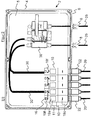
- FIG. 1 shows the internal structure of a known generator junction box.
- the strand lines 24 of the photovoltaic generator are connected to terminals of input modules 10a.
- the strand leads are passed through openings 8 in the circumferential side wall 6 of the terminal box housing 4 and connected inside the terminal box housing 4 to the terminals of the input modules 10a.
- a separate input module 10a is already needed only for the purpose of connecting the branch line.
- an electrical measuring module line 31 is laid to a measuring module 32, with which typically a single-phase current measurement is performed. From the measuring module 32, in turn, an electrical bridging module line 33 is laid for each bridging module 34 for each line of the PV generator to be connected. A bridging module 34 is used to bridge the individual PV strings and thus to collect the generated strand currents.
- further electrical connecting lines are arranged in the generator junction box, for example for the connection of a main circuit breaker 38 by means of a circuit breaker line 37 or for connecting further modules 36th
- the invention therefore has the task of solving the above problems or to reduce.
- Another object of the invention is to provide a generator junction box in which the cabling overhead within the generator junction box is reduced.
- Yet another object of the invention is to provide input modules which can be easily interconnected within the generator junction box, to which stranded lines can be connected quickly and safely and the installation effort is reduced by their use.
- a generator connection box for a photovoltaic generator has a connection box housing with a rear wall, a circumferential side wall and a front cover. If necessary, the rear wall has fastening holes for fastening the generator junction box at the installation site, for example on a house wall or on a support frame.
- the peripheral side wall has openings to connect the modules accommodated in the box box housing enclosed interior of the generator junction box with stranded lines and other electrical external connections.
- input modules are arranged such that the strand lines are connected directly from the outside to a quick connector of the associated input module, without having to open the front cover. This can be avoided within the generator junction box extending cable runs of the string lines.
- the string cables are connected directly from outside the terminal box housing to the quick connector of the input module.
- the quick connector of the input module extends from the inner region of the terminal box housing through the opening in the circumferential side wall into the outer area.
- the respective branch line outside the generator junction box is connected directly to the quick connector in the area of the circumferential side wall.
- an input module comes either on the side wall to the plant or it engages in the opening of the side wall.
- the input module is arranged to engage from the inside on or into the opening, so that the quick connector of the input module already abuts against the opening or engages in the opening when the input module is mounted in the generator connection box.
- the fast link which is part of the input module, is thus accessible from outside the generator junction box for direct connection of the line by: either the quick connector protrudes from the generator junction box or this comes to rest in the opening, so that the string line is connected directly to the input module.
- the front can be provided with a front in the form of a door that can be easily opened and thus provides access to the interior. If necessary, a door can even be dispensed with, since the fitter does not necessarily have to have access to the interior of the generator junction box.
- a door is provided which can only be opened by specially authorized personnel.
- the direct connection of the strand cables from the outside to the quick connector minimizes assembly times and thus costs.
- the connection of the stranded lines to the input modules of the generator junction box can take place without access to the interior area.
- the risk of faulty wiring within the generator junction box housing can thereby be reduced. Access to the inner area of the generator junction box is therefore not required for this embodiment of the invention.
- connection of the strand cables to the input modules can be done by means of the quick connector even without tools.
- the quick connectors have, in particular, an electrical insulation and / or contact and contact protected connections.
- sufficient contacts and contacts protected against contact can also be connected or disconnected in the event that an electrical voltage is already applied to the stranded lines, which is usually the case since the solar modules begin to produce electricity directly under exposure to sunlight ,
- junction box housing is protected against water, in particular according to protection class IP54, and is preferably made of dielectric material.
- the respective branch line to be connected to the connection box is equipped with a quick connector which is complementary to the quick connector of the input module. This allows a particularly quick and easy connection of the line and the input module in the generator junction box, especially when the quick connector of the stranded line and the quick connector of the input module are pre-assembled on both sides.
- the quick connector of the input module in particular with a from the outside of the side wall of the terminal box housing in the region of the openings operable connection device, such as a spring terminal, a tension spring or a screw terminal, equipped to contact the stripped conductor end of the strand line, without having to open the front cover of the terminal box housing.
- a strain relief of the strand line can be integrated in the quick connector, so that when connecting automatically a strain relief is created, in particular by means of a latching connection.
- an attachment of the strand conduit to the outside of the circumferential side wall of the generator junction box can take over the function of the strain relief, for example by means of a union nut, which is fastened to a mounted on the opening in the circumferential side wall external thread.
- the input modules for the positive pole and the negative pole are in particular identical.
- An input module arranged in the generator connection box is connected either to a line of the positive pole of the photovoltaic generator or to a line of the negative pole of the photovoltaic generator, depending on which pole the input module is assigned to. This can reduce production and logistics costs.
- a plurality of identical input modules are arranged, wherein a plurality of modules are associated with the positive pole of the photovoltaic generator, and one to several modules the negative pole associated with the photovoltaic generator.
- the input modules assigned to one pole of the photovoltaic generator can be directly bridged together by means of an electrically conductive current bridge attached to bridge contacts of the input modules, so that the individual strings are electrically connected to form a unit. A possibly required parallel connection of the string lines can therefore already take place in the input modules.
- a main disconnecting switch for disconnecting the photovoltaic generator from the power grid or from other components, such as inverters, is arranged in the generator junction box. If the terminal box housing has no door, then the main circuit breaker can also be arranged in the outer area, for example on the circumferential side wall, of the generator junction box. Thus, in any case, easy access to the main breaker is given.
- the generator junction box preferably comprises mounting means, for example a mounting plate or a mounting rail, in the junction box housing to which the input modules and, if appropriate, further modules to be arranged in the generator junction box are to be fastened, e.g. be snapped.
- mounting means for example a mounting plate or a mounting rail
- the quick connectors integrated in the input modules automatically position themselves in or directly at the openings of the peripheral side wall.
- the mounting rail is in particular a DIN rail on which the input modules can be latched and when snapped on the DIN rail, the quick connectors integrated in the input modules automatically come to rest in or directly on the openings of the generator junction box.
- the input modules and the mounting rail preferably have a linear guide, by means of which the input modules are guided from above down linearly to the associated opening in the side wall. Possibly.
- the connection hooks located on the back wall side of the input modules engage in receptacles of the mounting rail.
- a linear guide of the input modules is realized perpendicular to the lower part of the peripheral side wall, so that the quick connectors are inserted straight into the openings of the circumferential side wall.
- the connection hooks and the receptacles of the mounting rail are preferably tapered downwards, so that an exact positioning or centering of the input modules is achieved.
- connection hooks arranged on the rear wall side on the input modules engage in or under the receptacles of the mounting rail, so that a clamping action for fixing the input modules arises between the connection hooks and the receptacles.
- the quick connector when mounting the input module in the generator junction box, the quick connector preferably engages or comes into contact with the opening in the peripheral side wall, so that the input module is mounted in the generator junction box when it is plugged on or snapped onto the mounting rail.
- the strand leads and the quick connectors of the input modules preferably have complementary connection means, for example a screw connection, so that the input modules are automatically fastened to the side wall of the terminal box housing when attaching the strand lead.
- complementary connection means for example a screw connection
- the quick connector on the input module is in particular a connector, which is pluggable connectable with a complementary connector of the respective strand line.
- the connector according to the invention of the input module or the generator strand line extends through the opening in the circumferential side wall of the terminal box housing.
- the connection, in particular the plug connection, the stranded line with the input module without further measures, such as opening the terminal box door or laying the strand lines in the device connection box can be realized. This represents a significant reduction in the assembly time required to set up the connection.
- a connector for use as a quick connector is eg the product SunClix® the applicant.
- the SunClix® connector has an electrical contact protected against water by means of a dielectric housing and a clamping spring which can be latched in a holding frame. Further details, in particular about Plug geometry, resulting from the DE 10 2008 061 268 A1 ,
- the input modules are attached directly to the circumferential side wall, which can be dispensed with an attachment to the rear wall or on a mounting means.
- fastening means are, for example, latching or clamping means, which optionally engage in corresponding counterparts on the quick connector, or a threaded sleeve.
- the outer-side fastening means on the circumferential side wall may be an external thread on a collar-like surrounding the opening protuberance on which a union nut is screwed.
- the fastening means attached to the outside of the openings of the circumferential side wall in this embodiment take over the strain relief of the stranded conductors at the input modules.
- Such a fastening means may also comprise a sealing ring for waterproofing the passage through the circumferential side wall of the generator junction box.
- the quick connectors of the input modules have latching receptacles, latching hooks or a threaded sleeve.
- the quick connector of the input module is thereby guided into the opening of the circumferential side wall, so that the input module comes to rest on the side wall, and the union nut screwed from the outside to the outwardly projecting external thread of the quick connector, so as to screw the input module to the side wall.
- the input module for installation in the generator connection box for the photovoltaic system therefore comprises an integrated quick connector for directly connecting the electrical string of the photovoltaic system with the input module, wherein the quick connector when mounting the input module in the generator junction box in or directly on the associated opening in the peripheral side wall of the junction box to come to rest.
- the input module comes into contact with the mounting on the side wall or engages in the opening of the side wall, so that the direct connection of the strand line from outside to the input module arranged in the interior of the connection box housing is made possible.
- the input module is advantageously designed to fulfill a multiple function, which performs at least one additional function in addition to connecting the strand line.
- the input module according to the invention has a receptacle for a functional element.
- the functional element is for example a fuse, a current measuring device, a voltage detector or a microcontroller, which in the functional element recording be used.
- the voltage detector is either an overvoltage detector, for example as lightning protection, or an undervoltage detector to avoid hot spots, wherein voltage deviations lying outside of thresholds are detected and the electrical connection is interrupted in the presence of voltage deviations.
- the functional element holder is designed such that the functional element is exchangeable on the input module.
- the functional element holder for a replaceable functional element increases the flexibility of the input modules to be used in the generator junction box, since each input module can be equipped with the required functional element and inserted into the generator junction box.
- the functional element receptacle can even be configured such that different functional elements can be used alternately in the same functional element receptacle. This simplifies production processes and increases the number of identical input modules, which in turn can reduce unit costs.
- the input module particularly preferably has a plurality of functional element receptacles in order to use several, in particular different functional elements in one and the same input module.
- the input module preferably includes a laterally arranged paired connector for interconnecting two or more input modules to insert and secure multiple input modules as a unit into the generator junction box.
- the connected input modules are e.g. snapped as a unit on the top hat rail, wherein the primary side integrated quick connector of the input modules automatically come to rest on or in the associated opening of the terminal box housing.
- a possibly attached bus connection can be integrated in the laterally arranged pairable connection device.
- the input modules are attached directly to the peripheral side wall of the terminal box housing, can advantageously be dispensed with an attachment to the rear wall of the housing.
- FIG. 1 shows a known generator junction box 2 with a junction box housing 4, which has a circumferential side wall 6 and a rear wall 5.
- the circumferential side wall 6 has openings 8 for performing strand lines 24.
- various modules, the input modules 10a, the measuring module 32, connection module 34 and further modules 36, for example an overvoltage protection module, and a main circuit breaker 38 are arranged inside the generator junction box 2, and various modules, the input modules 10a, the measuring module 32, connection module 34 and further modules 36, for example an overvoltage protection module, and a main circuit breaker 38 are arranged.
- strand lines are individually passed through openings 8 of the circumferential side wall and connected in the interior of the generator junction box 2 to input modules 10a by means of screw.
- the input modules 10a correspond in the example shown simple connection terminals.
- the lines of the one electrical pole of the photovoltaic system strands are connected by means of electrical measuring module lines 31 to the input modules 10a with a measuring module 32 suitable for the installed line number for measuring the line currents.
- the measuring module 32 is in turn connected to bridging modules 34 for bridging and thus for collecting the single-strand currents.
- the collected power is finally passed via a circuit breaker line 37 to a main circuit breaker 38 and then usually passed via a power line 25 to a grid inverter (not shown).
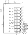
- FIG. 2 shows a first embodiment using the input modules 10 according to the invention in a generator junction box 2, the construction of the FIG. 2 significant differences to the generator junction box in FIG. 1 illustrated.
- the input modules 10 with their quick connectors 12 are arranged directly on the circumferential side wall 6 of the terminal box housing 4, so that the strand lines 20 directly from the outside on the side wall 6 to the quick connector 12th the input modules 10 are connected, without that the stranded lines 20 or other electrical lines in the inner region of the generator junction box 2 are to be laid.
- the input modules 10 have a plurality of functional element receptacles 11 for accommodating a respective fuse element 19c and a current measuring component 19a.
- Each two bridge contacts 19f are electrically arranged behind the current measuring device 19a on the input modules 10 for pairwise bridges of the input modules by means of current bridges 16 to collect the single-stranded currents and bundled lead via an electrical bus 30 to the main circuit breaker 38.
- the photovoltaic strings can already be connected in parallel in the input modules 10.
- the strand lines 20 can be quickly and easily connected to the input modules 10 by means of the quick connector 12, but it also several functions are integrated in a module, which simplifies the internal structure of a generator junction box 2.
- the input module 10 accordingly forms a combination module for connecting the string line, for measuring a measured variable, e.g. Electricity, and to bridge the parallel branch lines.
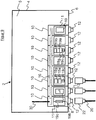
- FIG. 3 shows a simplified embodiment of the generator junction box 2 with a terminal box housing 4, which has a circumferential side wall 6, a rear wall 5 and a front side (not shown).
- the circumferential side wall 6 has openings 8, which are provided for the implementation of quick connectors 12 of the input modules 10 and quick connectors 22 of the strand lines 20.
- the input modules 10 are arranged directly on the circumferential side wall 6 of the terminal box housing 4, wherein the quick connectors 12 of the input modules 10 come to lie in the openings in the circumferential side wall 6 of the terminal box housing 4.
- the quick connectors 22, which are arranged at the end of the strand line 20, are complementarily connectable to the quick connectors 12 of the input modules.
- the strand lines 20 are quickly and easily connected to the input modules 10 in the generator junction box 2.
- the input modules 10 are electrically connected to each other by means of current bridges 16 by the current bridges 16 are each connected to a bridge contact 19 f of the input module 10.
- An electrical bus 30 discharges the collected power from the input modules.
- FIGS. 4 to 7 show a simple embodiment of a generator junction box with a mounting means in the form of a mounting rail 18.
- the input modules 10 on the rear side a tapered connection hook 14.
- This connection hook 14 of the input module 10 is in receptacles 15 of the mounting rail 18 by means of a linear movement of, in the image direction, top down inserted.
- a linear guide of the modules with centering is ensured by the connecting hooks to insert the quick connector 12 with a single hand movement safely in the openings 8 of the terminal box housing 4.
- FIG. 4 illustrated input module 10 is already arranged in the end position on the mounting rail 18, wherein the connecting hook 14 is inserted into the receptacle 15 on the mounting rail.
- connection hook 14 When the connection hook 14 is formed so as to partially engage with the receptacle 15 of the mounting rail 18 (not shown), a clamping force between the connection hook 14 of the input module 10 and the receptacle 15 of the mounting rail 18 can fix the input module 10 in the receptacle 15.
- SunClix® connectors of the applicant are outlined as quick connectors 12 of the input modules or quick connectors 22 of the stranded conductor 20.
- the SunClix® connectors have latching hooks 27, which engage in the assembled state in arranged on the input module 10 locking receptacles 27a and thus establish a secure connection by locking.
- the strand line 20 is zugentlastet with the latching hooks 27 on the locking receptacles 27a of the input module 10.
- Three further input modules 10 are shown in a not yet mounted state in the generator junction box 2.
- FIG. 5 shows the embodiment as FIG. 4 , wherein input modules and strand lines are also equipped with the SunClix® connectors, and wherein a second input module 10 is already attached to the rear-side connecting hook 14 on the mounting rail and also with the quick connector 12 directly in the opening 8 of the peripheral side wall 6 of the generator junction box 4 comes to rest.
- the quick connector 12 of the input module 10 extends through the opening in the circumferential side wall 6 of the terminal box housing 4 therethrough.
- the second input module 10 is also connected to a branch line 20; both input modules 10 are electrically connected to one another by means of a current bridge 16 connected to a bridge contact 19f.
- the use of a current bridge 16 between the input modules 10 allows only one electrical bus 30 to be used to dissipate the electrical power generated by the photovoltaic solar modules from the input modules 10.
- the second input module 10 is also connected by connecting the two quick connectors 12, 22 to the circumferential side wall 6 of the terminal box housing 4 attached, whereby a stable assembly takes place without having to rely on an additional screw or other connection. Also, by means of the quick connector 22, 12 a strain relief of the strand leads 20 allows. The two right in FIG. 5 illustrated input modules 10 are still in a non-assembled state.
- FIG. 6 shows the embodiment as FIG. 4 , wherein already three input modules 10 are mounted on a mounting rail and come to lie directly in the openings of the peripheral side wall 6 of the terminal box 4. Also, the third input module 10 is electrically connected by means of a bridge contact 19f via a current bridge 16 with the two already mounted input modules 10. The right input module 10 is still in the unassembled state.
- FIG. 7 shows the embodiment as FIG. 4 , wherein all four input modules 10 shown are attached to the mounting rail 18. Already the plugging of the input modules 10 on the mounting rail 18 may represent a satisfactory fixation of the input modules 10 by means of the clamping force of the connecting hooks 14 in the receptacles 15 of the mounting rail 18.
- the input modules 10 are fixed by attaching the quick connectors 12, 22 directly to the peripheral side wall 6 of the terminal box housing 4 surrounding the opening 8, e.g. screwed, clamped or locked.
- a sealing ring (not shown) is attached to the quick connector 22 of the stranded line 20, so that a water-protected closure of the opening 8 and thus of the generator junction box 2 is achieved during the connection.
- a sealing ring already connects the connecting line 20 with the input module 10 via the quick connectors 12, 22, the respective opening 8 of the terminal box housing 4 watertight.
- FIG. 8 shows an embodiment with eight plugged onto a mounting rail input modules 10, which are all electrically contacted with a common power bridge 16 with each other.
- a stripped conductor end 26 is inserted in this embodiment directly into the quick connector socket 12 of the input module 10, a union nut 28 on an external thread of the socket 12th screwed, which at the same time the input module is attached to the side wall and also by means of a ferrule a solid and zugentlastende connection of the strand line 24 is ensured with the input module 10.
- the current bridge 16 allows only one electrical bus 30 to be required to dissipate the electric current.
- the electrical bus 30 leads to a main circuit breaker 38 (see. Fig.2 ), which is typically also arranged in or on the generator junction box.
- FIG. 9 shows an embodiment of the generator junction box 2, wherein the input modules 10 are arranged directly on the circumferential side wall 6 of the terminal box housing 4 and fixed there directly. A mounting rail is not provided in this embodiment.
- the input modules 10 are electrically connected to one another via a current bridge 16.
- the input modules 10 have receptacles 11 for functional elements 19. For the arrangement of the functional elements 19 different possibilities are shown, each showing different configurations of the input modules 10.
- at least the input modules 10 of an electrical pole of the photovoltaic generator are embodied in the same configuration, so that the same functions are assigned to all the strings. But it is also possible to provide a combination of different configurations of the input modules 10 in a generator junction box 2.
- a fuse 19c is used as a functional element 19.
- a microcontroller 19b is used in the second input module 10.
- the arrangement of the third input module 10, in which a fuse 19c, a current measuring component 19a and a voltage detector 19g are integrated in an input module 10, is advantageous.
- a fuse 19c, a voltage detector 19g, a current measuring device 19a and a microcontroller 19b are integrated in the input module 10.
- the openings 8 in the circumferential side wall 6 of the terminal box housing 4 are watertight closed by the quick connectors of the input modules at least after connection to the quick connectors 22 of the strand lines 20.
- a bus connection for communication between the input modules, in the embodiment shown for example for communication between the current measuring device 19a and the microcontroller 19b and / or for connection to a central station such as a workstation, may additionally be integrated in all input modules 10.
Landscapes
- Engineering & Computer Science (AREA)
- Architecture (AREA)
- Civil Engineering (AREA)
- Structural Engineering (AREA)
- Photovoltaic Devices (AREA)
- Life Sciences & Earth Sciences (AREA)
- Sustainable Development (AREA)
- Sustainable Energy (AREA)
Description
- Die Erfindung betrifft einen Generatoranschlusskasten für einen Photovoltaikgenerator sowie Eingangsmodule zum Einbau in einen Generatoranschlusskasten.
- Bei einem Photovoltaikgenerator zur Erzeugung elektrischer Leistung aus Sonnenlicht wird der Gesamtgenerator typischerweise in einzelne Stränge bestehend aus mehreren seriell geschalteten photovoltaischen Solarmodulen unterteilt. Die einzelnen Stränge des Photovoltaikgenerators wiederum sind zueinander parallel geschaltet.
- Von jedem der zueinander parallel geschalteten Stränge wird typischerweise eine elektrische Verbindungsleitung zu einem Generatoranschlusskasten gelegt. Demgemäß werden die Leitungen aller Stränge in diesem Generatoranschlusskasten gebündelt.
- Die einzelnen Photovoltaikgeneratorstranganschlussleitungen, kurz Strangleitungen, werden für gewöhnlich einzeln durch die Gehäusewand in den Generatoranschlusskasten geführt, und innerhalb des Generatoranschlusskastens an dort befindliche Bauteile angeschlossen. Die elektrische Verbindung an den Bauteilen wird dabei typischerweise durch eine Klemm- oder Schraubverbindung realisiert. Bei einer Vielzahl an Strangleitungen ist dies umständlich und erfordert bei deren Anschluss an die Bauteile des Generatoranschlusskastens einen erheblichen Installationsaufwand. Darüber hinaus ist auch eine Zugentlastung der Strangleitung ggf. schwierig umzusetzen.
- Nach dem mit der Strangleitung verbundenen Bauteil sind in dem Generatoranschlusskasten ggf. weitere Bauteile zu installieren, beispielsweise Messbauteile für eine dort stattfindende Strangstrommessung, Verbindungsbauteile für eine Brückenverbindung von mehreren Strangleitungen oder auch ein Trennschalter zur Trennung des Gesamtgenerators von nachgeschalteten Komponenten, wie den Wechselrichtern zur Netzeinspeisung. Auch diese Bauteile sind aufwändig einzeln vom Installateur zu verkabeln.
- Die Gebrauchsmusterschrift
DE 20 2008 007 846 U1 zeigt eine Photovoltaikanlage mit einer Anschlussbox zum Verbinden von Solarzellen mit einem Wechselrichter. Die Anschlussbox weist ein Gehäuse auf, mehrere Sicherungen mit Sicherungskörpern und mehrere Anschlussklemmblöcke. Von den Solarmodulsträngen zur Anschlussbox führende Solarstromkabel sind an Steckverbinder der Anschlussbox anschließbar. -
Figur 1 zeigt den Innenaufbau eines bekannten Generatoranschlusskastens. Die Strangleitungen 24 des Photovoltaikgenerators werden an Terminals von Eingangsmodulen 10a angeschlossen. Hierfür werden die Strangleitungen durch Öffnungen 8 in der umlaufenden Seitenwand 6 des Anschlusskastengehäuses 4 hindurchgeführt und im Inneren des Anschlusskastengehäuses 4 an die Terminals der Eingangsmodule 10a angeschlossen. Für jede Strangleitung wird also bereits ein eigenes Eingangsmodul 10a nur zum Zweck des Anschließens der Strangleitung benötigt. - Von den Eingangsmodulen 10a, an welche die Strangleitungen 24 jeweils desselben Poles des Photovoltaikgenerators angeschlossen sind, wird je eine elektrische Messmodulleitung 31 zu einem Messmodul 32 gelegt, mit welchem typischerweise eine Einzelstrangstrommessung durchgeführt wird. Vom Messmodul 32 aus wird wiederum für jeden anzuschließenden Strang des PV-Generators eine elektrische Brückungsmodulleitung 33 zu je einem Brückungsmodul 34 gelegt. Ein Brückungsmodul 34 wird zur Brückung der einzelnen PV-Stränge und somit zum Sammeln der erzeugten Strangströme eingesetzt.
- Gegebenenfalls sind noch weitere elektrische Verbindungsleitungen im Generatoranschlusskasten angeordnet, beispielsweise für den Anschluss eines Haupttrennschalters 38 mittels einer Trennschalterleitung 37 oder zum Anschließen weiterer Module 36.
- Durch die aufwändige Verbindung der Strangleitungen mit den Eingangsmodulen sowie Montage und elektrische Verbindung der Vielzahl an benötigten unterschiedlichen Modulen 10a, 32, 34, 36 im Generatoranschlusskasten entstehen insgesamt unnötige Zeit- und Kostenfaktoren, die der bisherige Stand der Technik nicht zufriedenstellend zu verringern vermag.
- Die Erfindung hat sich daher die Aufgabe gestellt, die genannten Probleme zu lösen oder zu mindern.
- Es ist insbesondere eine Aufgabe der Erfindung, einen Generatoranschlusskasten bereitzustellen, der eine schnelle und sichere Verbindung der Strangleitungen an die in dem Generatoranschlusskasten befindlichen Module ermöglicht und den Installationsaufwand für den Monteur minimiert.
- Eine weitere Aufgabe der Erfindung ist es, einen Generatoranschlusskasten bereitzustellen, bei welchem der Verkabelungsaufwand innerhalb des Generatoranschlusskastens reduziert wird.
- Noch eine Aufgabe der Erfindung ist es, Eingangsmodule bereitzustellen, welche einfach innerhalb des Generatoranschlusskastens zusammengeschaltet werden können, an die schnell und sicher Strangleitungen angeschlossen werden können und durch deren Verwendung der Installationsaufwand reduziert wird.
- Die Aufgabe der Erfindung wird durch den Gegenstand der unabhängigen Ansprüche gelöst. Vorteilhafte Weiterbildungen der Erfindung sind in den Unteransprüche definiert.
- Erfindungsgemäß weist ein Generatoranschlusskasten für einen Photovoltaikgenerator ein Anschlusskastengehäuse auf mit einer Rückwand, einer umlaufenden Seitenwand und einer Frontabdeckung. Die Rückwand weist ggf. Befestigungslöcher zum Befestigen des Generatoranschlusskastens am Montageort, beispielsweise an einer Hauswand oder an einem Traggestell, auf. Die umlaufende Seitenwand weist Öffnungen auf, um die in dem von dem Anschlusskastengehäuse umschlossenen Innenraum des Generatoranschlusskastens beherbergten Module mit Strangleitungen und anderen elektrischen Außenverbindungen zu verbinden.
- Unmittelbar an der Innenseite der umlaufenden Seitenwand des Anschlusskastengehäuses sind Eingangsmodule angeordnet, derart, dass die Strangleitungen direkt von außen an einen Schnellverbinder des zugehörigen Eingangsmoduls anschließbar sind, ohne die Frontabdeckung öffnen zu müssen. Hiermit lassen sich innerhalb des Generatoranschlusskastens verlaufende Kabelstrecken der Strangleitungen vermeiden. Die Strangleitungen werden dabei direkt von außerhalb des Anschlusskastengehäuses an den Schnellverbinder des Eingangsmoduls angeschlossen.
- Bevorzugt erstreckt sich der Schnellverbinder des Eingangsmoduls aus dem Innenbereich des Anschlusskastengehäuses durch die Öffnung in der umlaufenden Seitenwand hindurch in den Außenbereich. In dieser Ausführungsform wird die jeweilige Strangleitung außerhalb des Generatoranschlusskastens unmittelbar im Bereich der umlaufenden Seitenwand an den Schnellverbinder angeschlossen.
- Mit anderen Worten kommt ein Eingangsmodul entweder an der Seitenwand zur Anlage oder es greift in die Öffnung der Seitenwand ein. Das heißt, dass das Eingangsmodul von innen an der oder in die Öffnung eingreifend angeordnet ist, so dass der Schnellverbinder des Eingangsmodul bereits beim Montieren des Eingangsmoduls in den Generatoranschlusskasten an der Öffnung anliegt oder in die Öffnung eingreift.
- Der Schneliverbinder, der Teil des Eingangsmoduls ist, ist somit von außerhalb des Generatoranschlusskastens für einen direkten Anschluss der Strangleitung erreichbar, indem entweder der Schnellverbinder aus dem Generatoranschlusskasten herausragt oder dieser in der Öffnung zu liegen kommt, so dass die Strangleitung unmittelbar an das Eingangsmodul angeschlossen wird.
- Zur leichten Erreichbarkeit des Innenbereichs des Generatoranschlusskastens kann die Vorderseite mit einer Frontseite in Form einer Tür versehen sein, die leicht geöffnet werden kann und damit einen Zugang zum Innenbereich darstellt. Auf eine Tür kann ggf. aber sogar verzichtet werden, da der Monteur nicht zwingend Zugang zum Innenbereich des Generatoranschlusskastens besitzen muss. Optional ist eine Tür vorgesehen, die nur von speziell autorisiertem Personal geöffnet werden kann.
- Das unmittelbare Anschließen der Strangleitungen von außen an den Schnellverbinder minimiert die Montagezeiten und damit Kosten. Beispielsweise kann mittels einer einfachen Identifizierung der jeweiligen Anschlüsse, insbesondere durch eine Farbkodierung, das Anschließen der Strangleitungen an die Eingangsmodule des Generatoranschlusskastens ohne Zugang zum Innenbereich erfolgen. Das Risiko einer fehlerhaften Verdrahtung innerhalb des Generatoranschlusskastengehäuses kann hierdurch verringert werden. Ein Zugriff auf den inneren Bereich des Generatoranschlusskastens wird für diese Ausführungsform der Erfindung daher nicht benötigt.
- Der Anschluss der Strangleitungen an die Eingangsmodule kann mittels der Schnellverbinder sogar ohne Werkzeug erledigt werden.
- Die Schnellverbinder weisen insbesondere eine elektrische Isolierung und/oder kontakt- und berührungsgeschützte Anschlüsse auf. Im getrennten Zustand ausreichend kontakt- und berührungsgeschützte Anschlüsse können auch für den Fall, dass bereits eine elektrische Spannung an den Strangleitungen anliegt, was in der Regel der Fall ist, da die Solarmodule unmittelbar unter Aussetzung von Sonnenlicht mit der Stromproduktion beginnen, angeschlossen oder abgeklemmt werden. Das bedeutet, dass auch im laufenden Betrieb und/oder bereits mit angeschlossenen photovoltaischen Solarmodulen die Wartung eines oder mehrerer Photovoltaikstränge ermöglicht sein kann, ohne die übrige Anlage abzuschalten. Im Besonderen bedeutet es, dass die Gefahr eines Stromschlags, die von den elektrischen Anschlüssen für den Monteur ausgeht, verringert ist.
- Das Anschlusskastengehäuse ist insbesondere nach Schutzklasse IP54 wassergeschützt und bevorzugt aus dielektrischem Material gefertigt.
- Die jeweilige mit dem Anschlusskasten zu verbindende Strangleitung ist mit einem zu dem Schnellverbinder des Eingangsmoduls komplementären Schnellverbinder ausgerüstet. Dies ermöglicht eine besonders schnelle und einfache Verbindung von Strangleitung und Eingangsmodul im Generatoranschlusskasten, insbesondere wenn der Schnellverbinder der Strangleitung und der Schnellverbinder des Eingangsmoduls beiderseits vormontiert sind.
- Zur Verbindung eines abisolierten Leiterendes einer Strangleitung mit dem Eingangsmodul ist der Schnellverbinder des Eingangsmoduls insbesondere mit einer von der Außenseite der Seitenwand des Anschlusskastengehäuses im Bereich der Öffnungen bedienbaren Anschlusseinrichtung, beispielsweise einer Federkraftklemme, einer Zugfeder oder einer Schraubklemme, ausgerüstet, um das abisolierte Leiterende der Strangleitung zu kontaktieren, ohne die Frontabdeckung des Anschlusskastengehäuses öffnen zu müssen.
- Beispielsweise kann eine Zugentlastung der Strangleitung in dem Schnellverbinder integriert sein, so dass beim Verbinden automatisch eine Zugentlastung geschaffen wird, insbesondere mittels einer Rastverbindung. Alternativ kann eine Befestigung der Strangleitung an der Außenseite der umlaufenden Seitenwand des Generatoranschlusskastens die Funktion der Zugentlastung übernehmen, beispielsweise mit Hilfe einer Überwurfmutter, die auf einem an der Öffnung in der umlaufenden Seitenwand angebrachten Außengewinde befestigt wird.
- Die Eingangsmodule für den Pluspol und den Minuspol sind insbesondere identisch ausgebildet. Ein im Generatoranschlusskasten angeordnetes Eingangsmodul ist entweder an eine Leitung des Pluspols des Photovoltaikgenerators oder an eine Leitung des Minuspols des Photovoltaikgenerators angeschlossen, je nachdem, zu welchem Pol das Eingangsmodul zugeordnet ist. Dadurch können Produktions- und Logistikkosten verringert werden.
- In dem Generatoranschlusskasten sind insbesondere mehrere identische Eingangsmodule angeordnet, wobei eine Mehrzahl von Modulen dem Pluspol des Photovoltaikgenerators zugehörig sind, sowie ein bis mehrere Module dem Minuspol des Photovoltaikgenerators zugeordnet sind. Gegebenenfalls können die zu einem Pol des Photovoltaikgenerators zugeordneten Eingangsmodule mittels einer elektrisch leitenden und an Brückenkontakten der Eingangsmodule angebrachten Strombrücke direkt miteinander gebrückt sein, so dass die einzelnen Stränge elektrisch zu einer Einheit verbunden werden. Eine ggf. erforderliche Parallelschaltung der Strangleitungen kann demnach bereits in den Eingangsmodulen stattfinden.
- In dem Generatoranschlusskasten ist ggf. ein Haupttrennschalter zum Trennen des Photovoltaikgenerators vom Stromnetz bzw. von weiteren Bauteilen, wie Wechselrichtern, angeordnet. Weist das Anschlusskastengehäuse keine Tür auf, so kann der Haupttrennschalter auch im Außenbereich, beispielsweise an der umlaufenden Seitenwand, des Generatoranschlusskastens angeordnet sein. Somit ist in jedem Fall der einfache Zugriff auf den Haupttrennschalter gegeben.
- Der Generatoranschlusskasten umfasst bevorzugt Montagemittel, beispielsweise eine Montageplatte oder eine Montageschiene, im Anschlusskastengehäuse, an der die Eingangsmodule und ggf. weitere im Generatoranschlusskasten anzuordnende Module zu befestigen sind, z.B. aufgerastet werden. Beim Montieren der Eingangsmodule auf das Montagemittel positionieren sich die in den Eingangsmodulen integrierten Schnellverbinder automatisch in oder unmittelbar an den Öffnungen der umlaufenden Seitenwand.
- Die Montageschiene ist insbesondere eine Hutschiene, auf der die Eingangsmodule aufrastbar sind und beim Aufrasten auf die Hutschiene die in den Eingangsmodulen integrierten Schnellverbinder automatisch in oder unmittelbar an den Öffnungen des Generatoranschlusskastens zu liegen kommen.
- Die Eingangsmodule und die Montageschiene weisen bevorzugt eine Linearführung auf, mittels welcher die Eingangsmodule von oben herab linear an die zugehörige Öffnung in der Seitenwand geführt werden. Ggf. greifen dabei rückwandseitig an den Eingangsmodulen befindliche Verbindungshaken in Aufnahmen der Montageschiene ein. Mittels der Verbindungshaken ist demnach eine lineare Führung der Eingangsmodule senkrecht zum unteren Teil der umlaufenden Seitenwand realisiert, so dass die Schnellverbinder gerade in die Öffnungen der umlaufenden Seitenwand eingeführt werden. Die Verbindungshaken sowie die Aufnahmen der Montageschiene sind bevorzugt nach unten verjüngend ausgebildet, so dass eine genaue Positionierung bzw. Zentrierung der Eingangsmodule erreicht wird.
- In einer bevorzugten Ausführungsform greifen die rückwandseitig an den Eingangsmodulen angeordneten Verbindungshaken in oder unter die Aufnahmen der Montageschiene, so dass zwischen den Verbindungshaken und den Aufnahmen eine Klemmwirkung zur Fixierung der Eingangsmodule entsteht.
- Bevorzugt greift daher beim Montieren des Eingangsmoduls in dem Generatoranschlusskasten der Schnellverbinder in die Öffnung in der umlaufenden Seitenwand ein oder kommt daran zur Anlage, so dass das Eingangsmodul mit dem Aufstecken oder Aufrasten auf die Montageschiene fertig in dem Generatoranschlusskasten montiert ist.
- Die Strangleitungen und die Schnellverbinder der Eingangsmodule weisen vorzugsweise komplementäre Verbindungsmittel auf, beispielsweise eine Schraubverbindung, so dass die Eingangsmodule beim Befestigen der Strangleitung automatisch an der Seitenwand des Anschlusskastengehäuses befestigt werden. Dadurch kann ggf. auf eine Befestigung der Eingangsmodule an der Generatoranschlusskastenrückwand verzichtet werden.
- Der Schnellverbinder am Eingangsmodul ist insbesondere ein Steckverbinder, welcher mit einem komplementären Steckverbinder der jeweiligen Strangleitung steckbar verbindbar ist. Zum Anschließen der Strangleitung an das Eingangsmodul erstreckt sich der erfindungsgemäße Steckverbinder des Eingangsmoduls oder der Generatorstrangleitung durch die Öffnung in der umlaufenden Seitenwand des Anschlusskastengehäuses. In beiden Fällen kann die Verbindung, insbesondere die Steckverbindung, der Strangleitung mit dem Eingangsmodul ohne weitere Maßnahmen, wie beispielsweise Öffnen der Anschlusskastentür oder Verlegen der Strangleitungen im Geräteanschlusskasten, realisiert werden. Dies stellt eine bedeutende Verkürzung der für den Aufbau der Verbindung benötigten Montagezeit dar.
- Ein Steckverbinder zur Verwendung als Schnellverbinder ist z.B. das Produkt SunClix® der Anmelderin. Der Steckverbinder SunClix® weist einen mittels eines dielektrischen Gehäuses wassergeschützten elektrischen Kontakt und eine in einem Haltegestell verrastbare Klemmfeder auf. Weitere Details, insbesondere zur Steckgeometrie, ergeben sich aus der
DE 10 2008 061 268 A1 . - In einer Ausführungsform der Erfindung sind die Eingangsmodule unmittelbar an der umlaufenden Seitenwand befestigt, wodurch auf eine Befestigung an der Rückwand oder an einem Montagemittel verzichtet werden kann.
- Beispielsweise weist die umlaufende Seitenwand für eine Befestigung der Eingangsmodule im Bereich der Öffnungen außenseitige Befestigungsmittel auf, mittels welchen die Schnellverbinder der Eingangsmodule in den Öffnungen in der umlaufenden Seitenwand befestigt werden. Solche Befestigungsmittel sind beispielsweise Rast- oder Klemmmittel, welche ggf. in entsprechende Gegenstücke am Schnellverbinder greifen, oder eine Gewindehülse. So kann das außenseitige Befestigungsmittel an der umlaufenden Seitenwand ein Außengewinde auf einer kragenartig die Öffnung umschließenden Ausstülpung sein, auf welches eine Überwurfmutter aufgeschraubt wird. Die außenseitig an den Öffnungen der umlaufenden Seitenwand angebrachten Befestigungsmittel übernehmen in dieser Ausführungsform die Zugentlastung der Strangleitungen an den Eingangsmodulen. Ein solches Befestigungsmittel kann zudem einen Dichtungsring zum wassergeschützten Abdichten der Durchführung durch die umlaufende Seitenwand des Generatoranschlusskastens aufweisen. Somit wird die Öffnung bereits bei der Verbindung mittels der Befestigungsmittel automatisch abgedichtet.
- In einem weiteren Beispiel für eine Befestigung der Eingangsmodule unmittelbar an der umlaufenden Seitenwand weisen die Schnellverbinder der Eingangsmodule Rastaufnahmen, Rasthaken oder eine Gewindehülse auf. Der Schnellverbinder des Eingangsmoduls wird dabei in die Öffnung der umlaufenden Seitenwand geführt, so dass das Eingangsmodul an der Seitenwand zur Anlage kommt, und die Überwurfmutter von außen auf das nach außen ragende Außengewinde des Schnellverbinders geschraubt, um damit das Eingangsmodul mit der Seitenwand zu verschrauben.
- Das Eingangsmodul zum Einbau in den Generatoranschlusskasten für die Photovoltaikanlage umfasst demnach einen integrierten Schnellverbinder zum direkten Verbinden der elektrischen Strangleitung der Photovoltaikanlage mit dem Eingangsmodul, wobei der Schnellverbinder beim Montieren des Eingangsmoduls in den Generatoranschlusskasten in oder unmittelbar an der zugeordneten Öffnung in der umlaufenden Seitenwand des Anschlusskastengehäuses zu liegen kommt. Mit anderen Worten kommt das Eingangsmodul bei der Montage an der Seitenwand zur Anlage oder greift in die Öffnung der Seitenwand ein, derart dass der direkte Anschluss der Strangleitung von außerhalb an das im Innern des Anschlusskastengehäuses angeordnete Eingangsmodul ermöglicht ist.
- Das Eingangsmodul ist in vorteilhafter Weise dazu ausgebildet, eine Mehrfachfunktion zu erfüllen, die zusätzlich zum Anschließen der Strangleitung zumindest eine weitere Funktion ausführt. Hierzu weist das Eingangsmodul gemäß der Erfindung eine Aufnahme für ein Funktionselement auf. Das Funktionselement ist z.B. eine Sicherung, ein Strommessbauteil, ein Spannungsdetektor oder ein Mikrokontroller, welche in die Funktionselementaufnahme eingesetzt werden. Der Spannungsdetektor ist entweder ein Überspannungsdetektor, z.B. als Blitzschutz, oder ein Unterspannungsdetektor zur Vermeidung von Hot Spots, wobei außerhalb von Schwellwerten liegende Spannungsabweichungen erkannt werden und die elektrische Verbindung beim Vorliegen von Spannungsabweichungen unterbrochen wird.
- Gemäß einer bevorzugten Ausführungsform ist die Funktionselementaufnahme derart ausgebildet, dass das Funktionselement an dem Eingangsmodul austauschbar ist. Die Funktionselementaufnahme für ein austauschbares Funktionselement erhöht die Flexibilität der in den Generatoranschlusskasten einzusetzenden Eingangsmodule, da jedes Eingangsmodul mit dem benötigten Funktionselement bestückt und in den Generatoranschlusskasten eingesetzt werden kann.
- Die Funktionselementaufnahme kann sogar derart ausgestaltet sein, dass verschiedene Funktionselemente im Wechsel in dieselbe Funktionselementaufnahme einsetzbar sind. Dies vereinfacht Produktionsabläufe und erhöht die Stückzahlen von identisch herzustellenden Eingangsmodulen, was wiederum die Stückkosten senken kann.
- Das Eingangsmodul weist besonders bevorzugt mehrere Funktionselementaufnahmen auf, um in ein und dasselbe Eingangsmodul mehrere, insbesondere unterschiedliche Funktionselemente einzusetzen. Hierdurch kann vorteilhafter Weise die Anzahl der Module im Generatoranschlusskasten und die Anzahl elektrischer Verbindungsleitungen auf ein Minimum reduziert werden. Überdies lässt sich die Baugröße des Generatoranschlusskastens weiter verkleinern.
- Das Eingangsmodul umfasst vorzugsweise eine seitlich angeordnete paarbare Verbindungseinrichtung zum wechselseitigen Verbinden von zwei oder mehr Eingangsmodulen, um mehrere Eingangsmodule als eine Einheit in den Generatoranschlusskasten einzusetzen und dort zu befestigen. Die verbundenen Eingangsmodule werden z.B. als Einheit auf die Hutschiene aufgerastet, wobei die primärseitig integrierten Schnellverbinder der Eingangsmodule automatisch jeweils an oder in der zugehörigen Öffnung des Anschlusskastengehäuses zu liegen kommen. Darüber hinaus kann ein ggf. angebrachter Bus-Anschluss in der seitlich angeordneten paarbaren Verbindungseinrichtung integriert sein.
- Wenn die Eingangsmodule direkt an der umlaufenden Seitenwand des Anschlusskastengehäuses befestigt sind, kann vorteilhafter Weise auf eine Befestigung an der Gehäuserückwand verzichtet werden.
- Im Folgenden wird die Erfindung anhand von Ausführungsbeispielen und unter Bezugnahme auf die Figuren näher erläutert, wobei gleiche und ähnliche Elemente teilweise mit gleichen Bezugszeichen versehen sind und die Merkmale der verschiedenen Ausführungsbeispiele miteinander kombiniert werden können.
- Es zeigen:
- Fig. 1
- einen bekannten Generatoranschlusskasten mit herkömmlichen Modulen und einem Haupttrennschalter,
- Fig. 2
- eine Ausführungsform eines erfindungsgemäßen Generatoranschlusskastens mit fünf Eingangsmodulen und Haupttrennschalter,
- Fig. 3
- eine Ausführungsform des Generatoranschlusskastens mit acht Eingangsmodulen,
- Fig. 4
- eine Ausführungsform des Generatoranschlusskastens mit vier Eingangsmodulen und einer Montageschiene,
- Fig. 5
- die Ausführungsform wie
Fig. 4 mit zwei montierten Eingangsmodulen, - Fig. 6
- die Ausführungsform wie
Fig. 4 mit drei montierten Eingangsmodulen, - Fig. 7
- die Ausführungsform wie
Fig. 4 mit vier montierten Eingangsmodulen, - Fig. 8
- eine weitere Ausführungsform des Generatoranschlusskastens mit acht montierten Eingangsmodulen sowie alternativen Strangleitungsanschlüssen,
- Fig. 9
- einen Generatoranschlusskasten mit weiteren Ausführungsformen von Eingangsmodulen.
-
Figur 1 zeigt einen bekannten Generatoranschlusskasten 2 mit einem Anschlusskastengehäuse 4, welches eine umlaufende Seitenwand 6 sowie eine Rückwand 5 aufweist. Die umlaufende Seitenwand 6 weist Öffnungen 8 zum Durchführen von Strangleitungen 24 auf. Im Inneren des Generatoranschlusskastens 2 sind verschiedene Module, die Eingangsmodule 10a, das Messmodul 32, Verbindungsmodul 34 und weitere Module 36, beispielsweise ein Überspannungsschutzmodul, sowie ein Haupttrennschalter 38 angeordnet. - An die in der
Figur 1 links dargestellten Eingangsmodule 10a für den Pluspol sind fünf Strangleitungen 24 angeschlossen. - Die in
Figur 1 gezeigten Strangleitungen werden einzeln durch Öffnungen 8 der umlaufenden Seitenwand hindurchgeführt und im Inneren des Generatoranschlusskastens 2 an Eingangsmodule 10a mittels Schraubverbindung angeschlossen. Die Eingangsmodule 10a entsprechen in dem gezeigten Beispiel einfachen Anschlussterminals. - Die Leitungen des einen elektrischen Pols der Photovoltaikanlagenstränge, üblicherweise des Pluspols, sind mittels elektrischen Messmodulleitungen 31 nach den Eingangsmodulen 10a mit einem zur installierten Strangzahl passenden Messmodul 32 zur Messung der Strangleitungsströme verbunden.
- Mittels der Brückungsmodulleitungen 33 ist das Messmodul 32 wiederum an Brückungsmodule 34 angeschlossen zur Brückung und somit zur Sammlung der Einzelstrangströme. Der gesammelte Strom wird schließlich über eine Trennschalterleitung 37 zu einem Haupttrennschalter 38 geführt und üblicherweise anschließend über eine Netzleitung 25 zu einem Netzwechselrichter (nicht dargestellt) geleitet.
- Der Stromfluss des anderen elektrischen Pols der Photovoltaikanlage, üblicherweise des Minuspols, wird im gezeigten Fall ausgangsseitig der Eingangsmodule 10a über eine elektrische Leitung 35 zu einem weiteren Modul 36 und anschließend über eine Trennschalterleitung 37 zum Haupttrennschalter 38 geführt.
-
Figur 2 zeigt eine erste Ausführungsform unter Verwendung der erfindungsgemäßen Eingangsmodule 10 in einem Generatoranschlusskasten 2, wobei der Aufbau derFigur 2 wesentliche Unterschiede zu dem Generatoranschlusskasten inFigur 1 veranschaulicht. Die Eingangsmodule 10 mit ihren Schnellverbindern 12 (in der gezeigten Ausführung jeweils vom komplementären Schnellverbinder 22 der Strangleitung 20 verdeckt) sind unmittelbar an der umlaufenden Seitenwand 6 des Anschlusskastengehäuses 4 angeordnet, so dass die Strangleitungen 20 direkt von außen an der Seitenwand 6 an die Schnellverbinder 12 der Eingangsmodule 10 angeschlossen sind, ohne dass dafür die Strangleitungen 20 oder andere elektrische Leitungen im inneren Bereich des Generatoranschlusskastens 2 zu verlegen sind. - Die Eingangsmodule 10 weisen in der gezeigten Ausführungsform mehrere Funktionselementaufnahmen 11 auf zur Aufnahme je eines Sicherungselements 19c und eines Strommessbauteils 19a. Je zwei Brückenkontakte 19f sind elektrisch gesehen hinter dem Strommessbauteil 19a an den Eingangsmodulen 10 angeordnet zum paarweisen Brücken der Eingangsmodule mittels Strombrücken 16, um die Einzelstrangströme zu sammeln und gebündelt über eine elektrische Sammelleitung 30 zum Haupttrennschalter 38 zu führen. Mit anderen Worten können die Photovoltaikstränge bereits in den Eingangsmodulen 10 parallel geschaltet werden. In vorteilhafter Weise lassen sich somit nicht nur die Strangleitungen 20 mittels der Schnellverbinder 12 schnell und einfach an die Eingangsmodule 10 anschließen, sondern es werden auch mehrere Funktionen in einem Modul integriert, was den Innenaufbau eines Generatoranschlusskastens 2 vereinfacht. Das Eingangsmodul 10 bildet demnach ein Kombinationsmodul zum Anschließen der Strangleitung, zum Messen einer Messgröße, z.B. Strom, und zum Brücken der parallelen Strangleitungen.
-
Figur 3 zeigt eine vereinfachte Ausführungsform des Generatoranschlusskastens 2 mit einem Anschlusskastengehäuse 4, welches eine umlaufende Seitenwand 6, eine Rückwand 5 sowie eine Vorderseite (nicht dargestellt) aufweist. Die umlaufende Seitenwand 6 weist Öffnungen 8 auf, die für die Durchführung von Schnellverbindern 12 der Eingangsmodule 10 bzw. Schnellverbindern 22 der Strangleitungen 20 vorgesehen sind. - Im Inneren des Generatoranschlusskastens 2 sind die Eingangsmodule 10 unmittelbar an der umlaufenden Seitenwand 6 des Anschlusskastengehäuses 4 angeordnet, wobei die Schnellverbinder 12 der Eingangsmodule 10 in den Öffnungen in der umlaufenden Seitenwand 6 des Anschlusskastengehäuses 4 zu liegen kommen.
- Die Schnellverbinder 22, die am Ende der Strangleitung 20 angeordnet sind, sind komplementär verbindbar mit den Schnellverbindern 12 der Eingangsmodule. Mittels der Schnellverbinder 22 sind die Strangleitungen 20 schnell und komfortabel mit den Eingangsmodulen 10 im Generatoranschlusskasten 2 verbindbar.
- Die Eingangsmodule 10 sind miteinander mittels Strombrücken 16 elektrisch verbunden, indem die Strombrücken 16 je an einem Brückenkontakt 19f des Eingangsmoduls 10 angeschlossen sind. Eine elektrische Sammelleitung 30 führt den gesammelten Strom von den Eingangsmodulen ab.
-
Figuren 4 bis 7 zeigen eine einfache Ausgestaltung eines Generatoranschlusskastens mit einem Montagemittel in Form einer Montageschiene 18. Wie inFigur 4 ersichtlich, weisen die Eingangsmodule 10 rückwandseitig einen sich verjüngenden Verbindungshaken 14 auf. Dieser Verbindungshaken 14 des Eingangsmoduls 10 ist in Aufnahmen 15 der Montageschiene 18 mittels einer Linearbewegung von, in Bildrichtung, oben nach unten einführbar. Somit wird durch die Verbindungshaken eine Linearführung der Module mit Zentrierung gewährleistet, um die Schnellverbinder 12 mit einer einzigen Handbewegung sicher in die Öffnungen 8 des Anschlusskastengehäuses 4 einzuführen. So ist das inFigur 4 links dargestellte Eingangsmodul 10 bereits in der Endposition an der Montageschiene 18 angeordnet, wobei der Verbindungshaken 14 in die Aufnahme 15 an der Montageschiene eingeführt ist. Wenn der Verbindungshaken 14 derart ausgebildet ist, dass er teilweise unter die Aufnahme 15 der Montageschiene 18 greift (nicht dargestellt), kann eine Klemmkraft zwischen dem Verbindungshaken 14 des Eingangsmoduls 10 und der Aufnahme 15 der Montageschiene 18 das Eingangsmodul 10 in der Aufnahme 15 fixieren. - In dem gezeigten Beispiel sind als Schnellverbinder 12 der Eingangsmodule bzw. Schnellverbinder 22 der Strangleitung 20 SunClix®-Verbinder der Anmelderin skizziert. Die SunClix®-Verbinder weisen Rasthaken 27 auf, die im montierten Zustand in am Eingangsmodul 10 angeordnete Rastaufnahmen 27a eingreifen und somit durch Verrastung eine sichere Verbindung herstellen.
- Die Strangleitung 20 ist mit den Rasthaken 27 an den Rastaufnahmen 27a des Eingangsmoduls 10 zugentlastet. Drei weitere Eingangsmodule 10 sind in einem noch nicht montierten Zustand im Generatoranschlusskasten 2 gezeigt.
-
Figur 5 zeigt die Ausführungsform wieFigur 4 , wobei Eingangsmodule und Strangleitungen ebenfalls mit den SunClix®-Verbindern ausgerüstet sind, und wobei bereits ein zweites Eingangsmodul 10 mit dem rückwandseitigen Verbindungshaken 14 an der Montageschiene befestigt ist und dabei gleichfalls mit dem Schnellverbinder 12 unmittelbar in der Öffnung 8 der umlaufenden Seitenwand 6 des Generatoranschlusskastengehäuses 4 zu liegen kommt. Anders ausgedrückt erstreckt sich der Schnellverbinder 12 des Eingangsmoduls 10 durch die Öffnung in der umlaufenden Seitenwand 6 des Anschlusskastengehäuses 4 hindurch. Auch das zweite Eingangsmodul 10 wird mit einer Strangleitung 20 verbunden, beide Eingangsmodule 10 sind mittels einer an einem Brückenkontakt 19f angeschlossenen Strombrücke 16 miteinander elektrisch verbunden. Die Verwendung einer Strombrücke 16 zwischen den Eingangsmodulen 10 gestattet das Verwenden von lediglich einer elektrischen Sammelleitung 30 zum Abführen des von den photovoltaischen Solarmodulen erzeugten elektrischen Stromes von den Eingangsmodulen 10. Auch das zweite Eingangsmodul 10 wird durch das Verbinden der beiden Schnellverbinder 12, 22 an der umlaufenden Seitenwand 6 des Anschlusskastengehäuses 4 befestigt, wodurch eine stabile Montage erfolgt, ohne auf eine zusätzliche Schraub- oder anderweitige Verbindung angewiesen zu sein. Auch ist mittels der Schnellverbinder 22, 12 eine Zugentlastung der Strangleitungen 20 ermöglicht. Die beiden rechten inFigur 5 dargestellten Eingangsmodule 10 befinden sich noch in einem nicht montierten Zustand. -
Figur 6 zeigt die Ausführungsform wieFigur 4 , wobei bereits drei Eingangsmodule 10 auf eine Montageschiene aufgesteckt sind und unmittelbar in den Öffnungen der umlaufenden Seitenwand 6 des Anschlussgehäusekastens 4 zu liegen kommen. Auch das dritte Eingangsmodul 10 ist mittels eines Brückenkontakts 19f über eine Strombrücke 16 mit den beiden bereits montierten Eingangsmodulen 10 elektrisch verbunden. Das rechte Eingangsmodul 10 befindet sich noch im nicht montierten Zustand. -
Figur 7 zeigt die Ausführungsform wieFigur 4 , wobei alle vier gezeigten Eingangsmodule 10 auf die Montageschiene 18 aufgesteckt sind. Bereits das Aufstecken der Eingangsmodule 10 auf die Montageschiene 18 kann eine zufriedenstellende Fixierung der Eingangsmodule 10 mittels der Klemmkraft der Verbindungshaken 14 in den Aufnahmen 15 der Montageschiene 18 darstellen. - In einer besonderen Ausgestaltung der Schnellverbinder 12, 22 der Eingangsmodule 10 werden die Eingangsmodule 10 befestigt, indem die Schnellverbinder 12, 22 unmittelbar an der die Öffnung 8 umgebenden umlaufenden Seitenwand 6 des Anschlusskastengehäuses 4 befestigt, z.B. verschraubt, geklemmt oder verrastet sind.
- An dem Schnellverbinder 22 der Strangleitung 20 ist in dieser Ausführung ein Dichtring (nicht dargestellt) angebracht, so dass beim Verbinden ein wassergeschützter Verschluss der Öffnung 8 und damit des Generatoranschlusskastens 2 erreicht wird. Mit anderen Worten verschließt bereits das Verbinden der Strangleitung 20 mit dem Eingangsmodul 10 über die Schnellverbinder 12, 22 die jeweilige Öffnung 8 des Anschlusskastengehäuses 4 wasserdicht.
-
Figur 8 zeigt eine Ausführungsform mit acht auf eine Montageschiene aufgesteckten Eingangsmodulen 10, welche alle mit einer gemeinsamen Strombrücke 16 miteinander elektrisch kontaktiert sind. Ein abisoliertes Leiterende 26 wird in dieser Ausführungsform direkt in die Schnellverbindungsbuchse 12 des Eingangsmoduls 10 gesteckt, eine Überwurfmutter 28 an einem Außengewinde der Buchse 12 festgeschraubt, wodurch gleichzeitig das Eingangsmodul an der Seitenwand befestigt wird und ebenfalls mittels einer Quetschhülse eine feste und zugentlastende Verbindung der Strangleitung 24 mit dem Eingangsmodul 10 gewährleistet ist. Auch in dieser Ausführungsform ermöglicht die Strombrücke 16, dass nur eine elektrische Sammelleitung 30 zum Abführen des elektrischen Stromes benötigt wird. Beispielsweise führt die elektrische Sammelleitung 30 zu einem Haupttrennschalter 38 (vgl.Fig.2 ), welcher typischerweise ebenfalls im oder am Generatoranschlusskasten angeordnet wird. -
Figur 9 zeigt schließlich eine Ausführungsform des Generatoranschlusskastens 2, wobei die Eingangsmodule 10 unmittelbar an der umlaufenden Seitenwand 6 des Anschlusskastengehäuses 4 angeordnet sind und dort direkt befestigt werden. Eine Montageschiene ist in dieser Ausführungsform nicht vorgesehen. Die Eingangsmodule 10 sind über eine Strombrücke 16 elektrisch miteinander verbunden. Die Eingangsmodule 10 weisen Aufnahmen 11 für Funktionselemente 19 auf. Für die Anordnung der Funktionselemente 19 werden verschiedene Möglichkeiten gezeigt, die jeweils verschiedene Ausgestaltungen der Eingangsmodule 10 zeigen. Typischerweise sind zumindest die Eingangsmodule 10 eines elektrischen Pols des Photovoltaikgenerators in derselben Ausgestaltung ausgeführt, so dass allen Strängen dieselben Funktionen zugeordnet sind. Es ist aber auch möglich, eine Kombination von verschiedenen Ausgestaltungen der Eingangsmodule 10 in einem Generatoranschlusskasten 2 vorzusehen. - Im Falle des linken Eingangsmoduls 10 ist eine Sicherung 19c als Funktionselement 19 eingesetzt. Bei dem zweiten Eingangsmodul 10 ist ein Mikrokontroller 19b eingesetzt. Vorteilhaft ist die Anordnung des dritten Eingangsmoduls 10, bei dem eine Sicherung 19c, ein Strommessbauteil 19a und ein Spannungsdetektor 19g integriert in einem Eingangsmodul 10 angeordnet sind. Gemäß dem sechsten Eingangsmodule 10 ist eine Sicherung 19c, ein Spannungsdetektor 19g, ein Strommessbauteil 19a sowie ein Mikrokontroller 19b integriert im Eingangsmodul 10 angeordnet.
- Demgemäß ist die Anbringung von mehreren Funktionselementen 19a, 19b, 19c, 19g in den Funktionselementaufnahmen 11 der Eingangsmodule 10 gewährleistet, wodurch sich getrennte Bauteile bzw. mehrere verschiedene Module einsparen lassen, da die erwünschten Funktionen bereits von den Eingangsmodulen 10 erfüllt werden können.
- Die Öffnungen 8 in der umlaufenden Seitenwand 6 des Anschlusskastengehäuses 4 werden durch die Schnellverbinder der Eingangsmodule zumindest nach dem Verbinden mit den Schnellverbindern 22 der Strangleitungen 20 wasserdicht verschlossen.
- Ein Bus-Anschluss (nicht dargestellt) zur Kommunikation zwischen den Eingangsmodulen, in der gezeigten Ausführungsform beispielsweise zur Kommunikation zwischen dem Strommessbauteil 19a und dem Mikrokontroller 19b und/oder zur Verbindung mit einer Zentralstelle wie einem Arbeitsplatzrechner, kann zusätzlich in allen Eingangsmodulen 10 integriert sein.
- Es ist dem Fachmann ersichtlich, dass die vorstehend beschriebenen Ausführungsformen beispielhaft zu verstehen sind und die Erfindung nicht auf diese beschränkt ist, sondern in vielfältiger Weise variiert werden kann, ohne die Erfindung zu verlassen. Ferner ist ersichtlich, dass die Merkmale unabhängig davon, ob sie in der Beschreibung, den Ansprüchen, den Figuren oder anderweitig offenbart sind, auch einzeln wesentliche Bestandteile der Erfindung definieren, selbst wenn sie zusammen mit anderen Merkmalen gemeinsam beschrieben sind.
-
- 2
- Generatoranschlusskasten
- 4
- Anschlusskastengehäuse
- 6
- umlaufende Seitenwand des Anschlusskastengehäuses
- 8
- Öffnung
- 10
- Eingangsmodul
- 10a
- Eingangsmodul
- 11
- Funktionselementaufnahme
- 12
- Schnellverbinder
- 14
- rückwandseitiger Verbindungshaken
- 15
- Aufnahme der Montageschiene
- 16
- Strombrücke
- 18
- Montageschiene oder Montageplatte
- 19
- Funktionselement
- 19a
- Strommessbauteil
- 19b
- Mikrokontroller
- 19c
- Sicherungselement
- 19f
- Brückenkontakt
- 19g
- Spannungsdetektor
- 20
- Strangleitung
- 22
- Schnellverbinder
- 23
- Dichtung
- 24
- Strangleitung
- 25
- Netzleitung
- 26
- abisoliertes Leiterende
- 27
- Rasthaken des SunClix®-Verbinders
- 27a
- Rastaufnahme des SunClix®-Verbinders
- 28
- Überwurfmutter
- 30
- elektrische Sammelleitung
- 31
- Messmodulleitung
- 32
- Messmodul
- 33
- Brückungsmodulleitung
- 34
- Brückungsmodul
- 35
- elektrische Leitung
- 36
- Weiteres Modul
- 37
- Trennschalterleitung
- 38
- Haupttrennschalter
Claims (14)
- Generatoranschlusskasten (2) für einen Photovoltaikgenerator, umfassendein Anschlusskastengehäuse (4) mit einer Rückwand und einer umlaufenden Seitenwand (6),Eingangsmodule (10) mit jeweils einem integrierten Schnellverbinder (12) zum Anschließen einer Strangleitung (20, 24) an das zugehörige Eingangsmodul (10),wobei die Eingangsmodule (10) unmittelbar an der umlaufenden Seitenwand (6) des Anschlusskastengehäuses (4) angeordnet sind derart, dass die Strangleitungen (20, 24) direkt von außen an den Schnellverbinder (12) des zugehörigen Eingangsmoduls anschließbar sind,gekennzeichnet durchzumindest eine Funktionselementaufnahme (11) zur Aufnahme eines Funktionselements (19) in das Eingangsmodul (10).
- Generatoranschlusskasten nach vorstehendem Anspruch,
wobei mehrere Eingangsmodule (10) mittels jeweils eines Brückenkontakts (19f) über eine Strombrücke (16) zu einem Stromsammelmodul Pluspol und/oder mehrere Eingangsmodule (10) zu einem Stromsammelmodul Minuspol zusammengeschlossen sind. - Generatoranschlusskasten nach einem der vorstehenden Ansprüche,
mit einem in dem Anschlusskastengehäuse (4) angeordneten Haupttrennschalter (38) zum Trennen des Photovoltaikgenerators vom Stromnetz. - Generatoranschlusskasten nach einem der vorstehenden Ansprüche,wobei in dem Anschlusskastengehäuse (4) eine Montageschiene (18) oder Montageplatte (18) zum Befestigen der Eingangsmodule (10) umfasst ist,wobei die Seitenwand (6) des Anschlusskastengehäuses (4) Öffnungen (8) aufweist und beim Montieren der Eingangsmodule (10) auf die Montageschiene (18) oder Montageplatte (18) die in den Eingangsmodulen (10) integrierten Schnellverbinder (12) in oder unmittelbar an den Öffnungen (8) zu liegen kommen.
- Generatoranschlusskasten nach vorstehendem Anspruch,
wobei die Montageschiene (18) eine Hutschiene ist, auf der die Eingangsmodule (10) aufrastbar sind und beim Aufrasten auf die Hutschiene die in den Eingangsmodulen (10) integrierten Schnellverbinder (12) in oder unmittelbar an den Öffnungen (8) des Generatoranschlusskastens (2) zu liegen kommen. - Generatoranschlusskasten nach Anspruch 4,
wobei die Montageschiene (18) Aufnahmen (15) zur Aufnahme von an den Eingangsmodulen (10) rückwandseitig angeordneten Verbindungshaken (14) (10) aufweist, um die Eingangsmodule (10) mittels der Verbindungshaken (14) an der Montageschiene (18) auszurichten und/oder zu befestigen. - Generatoranschlusskasten nach einem der vorstehenden Ansprüche,wobei der Schnellverbinder (12) am Eingangsmodul (10) als Steckverbinder ausgebildet ist und mit einem komplementären Steckverbinder (22) der jeweiligen Strangleitung (20, 24) steckbar verbindbar ist undwobei sich der Steckverbinder (12) des Eingangsmoduls (10) durch die Öffnung (8) in der umlaufenden Seitenwand (6) des Anschlusskastengehäuses (4) hindurch erstreckt oderwobei sich in dem zusammengesteckten Zustand der Steckverbinder (12) der Strangleitung (20, 24) durch die Öffnung (8) in der umlaufenden Seitenwand (6) des Anschlusskastengehäuses (4) hindurch erstreckt.
- Generatoranschlusskasten nach einem der Ansprüche 1 bis 5,
wobei der Schnellverbinder (12) am Eingangsmodul (10) eine Gewindehülse aufweist und
wobei mittels einer Überwurfmutter (28) an der Strangleitung (20, 24) die Strangleitung an dem Eingangsmodul (10) des Generatoranschlusskastens (2) befestigbar ist, wenn ein abisoliertes Kabelende an dem Eingangsmodul (10) angeschlossen ist. - Generatoranschlusskasten nach vorstehendem Anspruch,
wobei die Eingangsmodule Dichtungen (23) zum wassergeschützten Verschließen der Öffnungen (8) umfassen. - Eingangsmodul zur Schnellmontage in einem Generatoranschlusskasten nach einem der vorstehenden Ansprüche, umfassend:einen integrierten Schnellverbinder (12) zum direkten Verbinden mit einer elektrischen Strangleitung (20, 24) einer Photovoltaikanlage mit dem Eingangsmodul (10),wobei der Schnellverbinder (12) beim Montieren des Eingangsmoduls (10) in den Generatoranschlusskasten (2) in oder unmittelbar an einer Öffnung (8) in der umlaufenden Seitenwand (6) des Anschlusskastengehäuses (4) zu liegen kommt,gekennzeichnet durchzumindest eine Funktionselementaufnahme (11) zur Aufnahme eines Funktionselements (19) in das Eingangsmodul (10).
- Eingangsmodul nach vorstehendem Anspruch, wobei das Funktionselement (19) austauschbar an dem Eingangsmodul (10) ausgeführt ist.
- Eingangsmodul nach vorstehendem Anspruch,
wobei das Funktionselement (19) eine Sicherung (19c), ein Strommessbauteil (19a), ein Mikrokontroller (19b) und/oder ein Spannungsdetektor (19g) ist. - Eingangsmodul nach Anspruch 12 ,
wobei mehrere Funktionselementaufnahmen (11) in einem Eingangsmodul (10) integriert sind. - Eingangsmodul nach einem der Ansprüche 10 bis 13, ferner umfassend:paarbare Befestigungsmittel zur gegenseitigen Befestigung von zwei oder mehr Eingangsmodulen (10), um mehrere Eingangsmodule (10) als Einheit auf eine Hutschiene (18) aufzurasten,wobei die integrierten Schnellverbinder (12) der Eingangsmodule (10) automatisch jeweils an oder in der zugehörigen Öffnung (8) des Anschlusskastengehäuses (4) zu liegen kommen.
Applications Claiming Priority (2)
| Application Number | Priority Date | Filing Date | Title |
|---|---|---|---|
| DE102011119173A DE102011119173B4 (de) | 2011-11-23 | 2011-11-23 | Generatoranschlusskasten fürPhotovoltaikanlagen und Eingangsmodule |
| PCT/EP2012/073538 WO2013076285A1 (de) | 2011-11-23 | 2012-11-23 | Generatoranschlusskasten für photovoltaikanlagen |
Publications (2)
| Publication Number | Publication Date |
|---|---|
| EP2783397A1 EP2783397A1 (de) | 2014-10-01 |
| EP2783397B1 true EP2783397B1 (de) | 2017-12-27 |
Family
ID=47356010
Family Applications (1)
| Application Number | Title | Priority Date | Filing Date |
|---|---|---|---|
| EP12799526.4A Not-in-force EP2783397B1 (de) | 2011-11-23 | 2012-11-23 | Generatoranschlusskasten für photovoltaikanlagen |
Country Status (5)
| Country | Link |
|---|---|
| US (1) | US9466961B2 (de) |
| EP (1) | EP2783397B1 (de) |
| CN (1) | CN103999356B (de) |
| DE (1) | DE102011119173B4 (de) |
| WO (1) | WO2013076285A1 (de) |
Families Citing this family (9)
| Publication number | Priority date | Publication date | Assignee | Title |
|---|---|---|---|---|
| TWM423402U (en) * | 2011-10-18 | 2012-02-21 | Ji-Ren Yang | Bus box |
| CA2997722A1 (en) | 2015-08-06 | 2017-02-09 | Hubbell Incorporated | Outdoor floor box enclosure |
| US20170295665A1 (en) * | 2016-04-08 | 2017-10-12 | Commscope Technologies Llc | Pre-terminated overvoltage protection module for electronics cabinet |
| US10424924B2 (en) | 2016-05-19 | 2019-09-24 | Consolidated Edison Company Of New York, Inc. | Utility grid generator connection |
| JP7097053B2 (ja) * | 2018-04-16 | 2022-07-07 | エンゼル工業株式会社 | 太陽電池パネル保守点検用接続器具 |
| CN108709244A (zh) * | 2018-06-26 | 2018-10-26 | 上海晶成电气有限公司 | 空调风机盘管与控制器的快速连接结构及空调的集控系统 |
| DE202019104906U1 (de) * | 2019-09-05 | 2021-01-08 | Wago Verwaltungsgesellschaft Mbh | Verbindungsdose zur Aufnahme von Anschlussklemmen |
| CN112582956A (zh) * | 2020-11-23 | 2021-03-30 | 安徽吉利电气设备有限公司 | 一种多媒体集线箱分组结构 |
| CN116125340B (zh) * | 2022-10-11 | 2026-02-03 | 国网福建省电力有限公司 | 一种用电线路防串户控制系统 |
Family Cites Families (17)
| Publication number | Priority date | Publication date | Assignee | Title |
|---|---|---|---|---|
| US4654470A (en) * | 1983-10-31 | 1987-03-31 | Amp Incorporated | Raintight junction box |
| US6456203B1 (en) * | 2000-04-03 | 2002-09-24 | Adc Telecommunications, Inc. | Power distribution panel with modular elements |
| DE102004021835B4 (de) * | 2004-05-04 | 2006-05-11 | Tyco Electronics Amp Gmbh | Geräteklemme |
| CN101272039B (zh) * | 2007-03-23 | 2010-04-14 | 励国庆 | 快速接线盒 |
| DE102008008503A1 (de) | 2008-02-11 | 2009-08-20 | Siemens Aktiengesellschaft | PV-Teilgenerator-Anschlusskasten, PV-Generator-Anschlusskasten und PV-Wechselrichter für eine PV-Anlage sowie PV-Anlage |
| DE202008007846U1 (de) * | 2008-06-12 | 2008-10-30 | EFG Energie für Gebäude GmbH & Co. KG | Fotovoltaikanlage |
| CN201260137Y (zh) | 2008-07-18 | 2009-06-17 | 泰科电子(上海)有限公司 | 建筑光伏一体化接线盒 |
| CN101651262B (zh) * | 2008-08-12 | 2012-03-21 | 凡甲电子(苏州)有限公司 | 太阳能电池板连接盒 |
| DE102008061268B4 (de) | 2008-12-10 | 2017-02-23 | Phoenix Contact Gmbh & Co. Kg | Kontaktklemme und Verbinder mit Kontaktklemme |
| DE102009036281A1 (de) * | 2009-08-06 | 2011-02-10 | Phoenix Contact Gmbh & Co. Kg | Elektrische Verbindung zwischen einem Verbindungselement und einem Kabel |
| DE202010006110U1 (de) * | 2010-04-26 | 2011-09-05 | Diehl Ako Stiftung & Co. Kg | Anschlussvorrichtung für einen Wechselrichter |
| CN201754409U (zh) * | 2010-06-30 | 2011-03-02 | 比亚迪股份有限公司 | 一种太阳能电池接线盒 |
| US20120033392A1 (en) * | 2010-08-09 | 2012-02-09 | Tyco Electronics Corporation | Modular Junction Box for a Photovoltaic Module |
| US8310333B2 (en) * | 2010-09-03 | 2012-11-13 | Cooper Technologies Company | Modular fuse holder |
| US8388358B2 (en) * | 2010-09-28 | 2013-03-05 | Tyco Electronics Corporation | Contact rail for a junction box |
| CA2752914C (en) * | 2010-09-29 | 2019-06-04 | Hosiden Corporation | Terminal box, output cable connection arrangement for solar cell module terminal box and fixation arrangement for the output cable |
| DE202011000284U1 (de) * | 2011-02-08 | 2011-05-12 | Laing, Karsten | Funktionsüberprüfungseinrichtung für Photovoltaikanlagen |
-
2011
- 2011-11-23 DE DE102011119173A patent/DE102011119173B4/de not_active Expired - Fee Related
-
2012
- 2012-11-23 WO PCT/EP2012/073538 patent/WO2013076285A1/de not_active Ceased
- 2012-11-23 EP EP12799526.4A patent/EP2783397B1/de not_active Not-in-force
- 2012-11-23 US US14/359,680 patent/US9466961B2/en not_active Expired - Fee Related
- 2012-11-23 CN CN201280057685.2A patent/CN103999356B/zh not_active Expired - Fee Related
Also Published As
| Publication number | Publication date |
|---|---|
| DE102011119173A1 (de) | 2013-05-23 |
| US20140352998A1 (en) | 2014-12-04 |
| EP2783397A1 (de) | 2014-10-01 |
| DE102011119173B4 (de) | 2013-11-28 |
| CN103999356A (zh) | 2014-08-20 |
| US9466961B2 (en) | 2016-10-11 |
| CN103999356B (zh) | 2017-04-26 |
| WO2013076285A1 (de) | 2013-05-30 |
Similar Documents
| Publication | Publication Date | Title |
|---|---|---|
| DE102011119173B4 (de) | Generatoranschlusskasten fürPhotovoltaikanlagen und Eingangsmodule | |
| WO2014198856A1 (de) | Kabelmodul für modulwechselrichter eines photovoltaikgenerators | |
| DE102010002565B3 (de) | Anschlussvorrichtung für eiin Solarmodul | |
| DE69932764T2 (de) | Abpassbare Abgangsbaugruppe einer Niederspannungs-Schaltzelle | |
| EP2745327A1 (de) | Anschlussdose für ein solarpanel mit einer schutzschaltung | |
| WO2007101682A2 (de) | Fotovoltaikanlage | |
| DE202008007846U1 (de) | Fotovoltaikanlage | |
| DE102017011373A1 (de) | Mess- und Steuerelektronik für Niederspannungsschaltanlagen | |
| DE202024101641U1 (de) | Hausstromunterverteiler | |
| EP2533302A2 (de) | Solarmodul und Photovoltaik-Anlage | |
| DE102021111396B4 (de) | Adapter für einen Sammelschienenträger | |
| EP2365506A1 (de) | Sicherungsleiste sowie Anordnung mit einer solchen Sicherungsleiste | |
| DE102010022024A1 (de) | Energieversorgungsvorrichtung mit kompaktem Hochspannungsanschluss | |
| DE10230393B4 (de) | Frontseitige Abdeckung | |
| DE102005025932B4 (de) | Anschlusseinrichtung mit Hauptsammelschienen, einer Schutzschaltereinheit und einer Zählerfeldeinheit | |
| DE102007054551B3 (de) | Baustromanschlussvorrichtung für Niederspannugsverteilung | |
| DE102008062108B4 (de) | Umrichtersystem | |
| EP1463074B1 (de) | Anordnung zur Verwendung bei einer elektrischen Installationsanlage | |
| DE19516327C1 (de) | Vorrichtung zur Messung von elektrischen Größen an einem Leistungsabgang in einer Niederspannungs-Schaltanlage | |
| EP3796474A2 (de) | Anschlussvorrichtung zum elektrischen kontaktieren eines elektrogeräts | |
| EP1050938A2 (de) | Netzanschluss-Tischgerät | |
| EP4049347B1 (de) | Steckverbinder mit sicherungshalter | |
| DE10233279A1 (de) | Photovoltaikmodul mit einem Photovoltaikelement und einem Wandlerelement sowie ein zugehöriges Photovoltaiksystem | |
| WO2006027306A1 (de) | Strom-einspeisemodul mit käfig-zugfederklemmen | |
| DE102024109434A1 (de) | Hausstromunterverteiler |
Legal Events
| Date | Code | Title | Description |
|---|---|---|---|
| PUAI | Public reference made under article 153(3) epc to a published international application that has entered the european phase |
Free format text: ORIGINAL CODE: 0009012 |
|
| 17P | Request for examination filed |
Effective date: 20140411 |
|
| AK | Designated contracting states |
Kind code of ref document: A1 Designated state(s): AL AT BE BG CH CY CZ DE DK EE ES FI FR GB GR HR HU IE IS IT LI LT LU LV MC MK MT NL NO PL PT RO RS SE SI SK SM TR |
|
| DAX | Request for extension of the european patent (deleted) | ||
| STAA | Information on the status of an ep patent application or granted ep patent |
Free format text: STATUS: EXAMINATION IS IN PROGRESS |
|
| 17Q | First examination report despatched |
Effective date: 20170116 |
|
| GRAP | Despatch of communication of intention to grant a patent |
Free format text: ORIGINAL CODE: EPIDOSNIGR1 |
|
| STAA | Information on the status of an ep patent application or granted ep patent |
Free format text: STATUS: GRANT OF PATENT IS INTENDED |
|
| INTG | Intention to grant announced |
Effective date: 20170714 |
|
| GRAS | Grant fee paid |
Free format text: ORIGINAL CODE: EPIDOSNIGR3 |
|
| GRAA | (expected) grant |
Free format text: ORIGINAL CODE: 0009210 |
|
| STAA | Information on the status of an ep patent application or granted ep patent |
Free format text: STATUS: THE PATENT HAS BEEN GRANTED |
|
| AK | Designated contracting states |
Kind code of ref document: B1 Designated state(s): AL AT BE BG CH CY CZ DE DK EE ES FI FR GB GR HR HU IE IS IT LI LT LU LV MC MK MT NL NO PL PT RO RS SE SI SK SM TR |
|
| REG | Reference to a national code |
Ref country code: GB Ref legal event code: FG4D Free format text: NOT ENGLISH |
|
| REG | Reference to a national code |
Ref country code: CH Ref legal event code: EP |
|
| REG | Reference to a national code |
Ref country code: AT Ref legal event code: REF Ref document number: 958997 Country of ref document: AT Kind code of ref document: T Effective date: 20180115 |
|
| REG | Reference to a national code |
Ref country code: IE Ref legal event code: FG4D Free format text: LANGUAGE OF EP DOCUMENT: GERMAN |
|
| REG | Reference to a national code |
Ref country code: DE Ref legal event code: R096 Ref document number: 502012011917 Country of ref document: DE |
|
| PG25 | Lapsed in a contracting state [announced via postgrant information from national office to epo] |
Ref country code: FI Free format text: LAPSE BECAUSE OF FAILURE TO SUBMIT A TRANSLATION OF THE DESCRIPTION OR TO PAY THE FEE WITHIN THE PRESCRIBED TIME-LIMIT Effective date: 20171227 Ref country code: LT Free format text: LAPSE BECAUSE OF FAILURE TO SUBMIT A TRANSLATION OF THE DESCRIPTION OR TO PAY THE FEE WITHIN THE PRESCRIBED TIME-LIMIT Effective date: 20171227 Ref country code: NO Free format text: LAPSE BECAUSE OF FAILURE TO SUBMIT A TRANSLATION OF THE DESCRIPTION OR TO PAY THE FEE WITHIN THE PRESCRIBED TIME-LIMIT Effective date: 20180327 |
|
| REG | Reference to a national code |
Ref country code: NL Ref legal event code: MP Effective date: 20171227 |
|
| REG | Reference to a national code |
Ref country code: LT Ref legal event code: MG4D |
|
| PG25 | Lapsed in a contracting state [announced via postgrant information from national office to epo] |
Ref country code: RS Free format text: LAPSE BECAUSE OF FAILURE TO SUBMIT A TRANSLATION OF THE DESCRIPTION OR TO PAY THE FEE WITHIN THE PRESCRIBED TIME-LIMIT Effective date: 20171227 Ref country code: GR Free format text: LAPSE BECAUSE OF FAILURE TO SUBMIT A TRANSLATION OF THE DESCRIPTION OR TO PAY THE FEE WITHIN THE PRESCRIBED TIME-LIMIT Effective date: 20180328 Ref country code: LV Free format text: LAPSE BECAUSE OF FAILURE TO SUBMIT A TRANSLATION OF THE DESCRIPTION OR TO PAY THE FEE WITHIN THE PRESCRIBED TIME-LIMIT Effective date: 20171227 Ref country code: HR Free format text: LAPSE BECAUSE OF FAILURE TO SUBMIT A TRANSLATION OF THE DESCRIPTION OR TO PAY THE FEE WITHIN THE PRESCRIBED TIME-LIMIT Effective date: 20171227 Ref country code: BG Free format text: LAPSE BECAUSE OF FAILURE TO SUBMIT A TRANSLATION OF THE DESCRIPTION OR TO PAY THE FEE WITHIN THE PRESCRIBED TIME-LIMIT Effective date: 20180327 |
|
| PG25 | Lapsed in a contracting state [announced via postgrant information from national office to epo] |
Ref country code: NL Free format text: LAPSE BECAUSE OF FAILURE TO SUBMIT A TRANSLATION OF THE DESCRIPTION OR TO PAY THE FEE WITHIN THE PRESCRIBED TIME-LIMIT Effective date: 20171227 |
|
| PG25 | Lapsed in a contracting state [announced via postgrant information from national office to epo] |
Ref country code: SK Free format text: LAPSE BECAUSE OF FAILURE TO SUBMIT A TRANSLATION OF THE DESCRIPTION OR TO PAY THE FEE WITHIN THE PRESCRIBED TIME-LIMIT Effective date: 20171227 Ref country code: ES Free format text: LAPSE BECAUSE OF FAILURE TO SUBMIT A TRANSLATION OF THE DESCRIPTION OR TO PAY THE FEE WITHIN THE PRESCRIBED TIME-LIMIT Effective date: 20171227 Ref country code: EE Free format text: LAPSE BECAUSE OF FAILURE TO SUBMIT A TRANSLATION OF THE DESCRIPTION OR TO PAY THE FEE WITHIN THE PRESCRIBED TIME-LIMIT Effective date: 20171227 Ref country code: CY Free format text: LAPSE BECAUSE OF FAILURE TO SUBMIT A TRANSLATION OF THE DESCRIPTION OR TO PAY THE FEE WITHIN THE PRESCRIBED TIME-LIMIT Effective date: 20171227 Ref country code: CZ Free format text: LAPSE BECAUSE OF FAILURE TO SUBMIT A TRANSLATION OF THE DESCRIPTION OR TO PAY THE FEE WITHIN THE PRESCRIBED TIME-LIMIT Effective date: 20171227 |
|
| PG25 | Lapsed in a contracting state [announced via postgrant information from national office to epo] |
Ref country code: IS Free format text: LAPSE BECAUSE OF FAILURE TO SUBMIT A TRANSLATION OF THE DESCRIPTION OR TO PAY THE FEE WITHIN THE PRESCRIBED TIME-LIMIT Effective date: 20180427 Ref country code: IT Free format text: LAPSE BECAUSE OF FAILURE TO SUBMIT A TRANSLATION OF THE DESCRIPTION OR TO PAY THE FEE WITHIN THE PRESCRIBED TIME-LIMIT Effective date: 20171227 Ref country code: PL Free format text: LAPSE BECAUSE OF FAILURE TO SUBMIT A TRANSLATION OF THE DESCRIPTION OR TO PAY THE FEE WITHIN THE PRESCRIBED TIME-LIMIT Effective date: 20171227 Ref country code: SM Free format text: LAPSE BECAUSE OF FAILURE TO SUBMIT A TRANSLATION OF THE DESCRIPTION OR TO PAY THE FEE WITHIN THE PRESCRIBED TIME-LIMIT Effective date: 20171227 Ref country code: RO Free format text: LAPSE BECAUSE OF FAILURE TO SUBMIT A TRANSLATION OF THE DESCRIPTION OR TO PAY THE FEE WITHIN THE PRESCRIBED TIME-LIMIT Effective date: 20171227 |
|
| PG25 | Lapsed in a contracting state [announced via postgrant information from national office to epo] |
Ref country code: MT Free format text: LAPSE BECAUSE OF FAILURE TO SUBMIT A TRANSLATION OF THE DESCRIPTION OR TO PAY THE FEE WITHIN THE PRESCRIBED TIME-LIMIT Effective date: 20171227 |
|
| REG | Reference to a national code |
Ref country code: DE Ref legal event code: R097 Ref document number: 502012011917 Country of ref document: DE |
|
| PLBE | No opposition filed within time limit |
Free format text: ORIGINAL CODE: 0009261 |
|
| STAA | Information on the status of an ep patent application or granted ep patent |
Free format text: STATUS: NO OPPOSITION FILED WITHIN TIME LIMIT |
|
| PG25 | Lapsed in a contracting state [announced via postgrant information from national office to epo] |
Ref country code: DK Free format text: LAPSE BECAUSE OF FAILURE TO SUBMIT A TRANSLATION OF THE DESCRIPTION OR TO PAY THE FEE WITHIN THE PRESCRIBED TIME-LIMIT Effective date: 20171227 |
|
| 26N | No opposition filed |
Effective date: 20180928 |
|
| PG25 | Lapsed in a contracting state [announced via postgrant information from national office to epo] |
Ref country code: SI Free format text: LAPSE BECAUSE OF FAILURE TO SUBMIT A TRANSLATION OF THE DESCRIPTION OR TO PAY THE FEE WITHIN THE PRESCRIBED TIME-LIMIT Effective date: 20171227 |
|
| REG | Reference to a national code |
Ref country code: CH Ref legal event code: PL |
|
| GBPC | Gb: european patent ceased through non-payment of renewal fee |
Effective date: 20181123 |
|
| PG25 | Lapsed in a contracting state [announced via postgrant information from national office to epo] |
Ref country code: MC Free format text: LAPSE BECAUSE OF FAILURE TO SUBMIT A TRANSLATION OF THE DESCRIPTION OR TO PAY THE FEE WITHIN THE PRESCRIBED TIME-LIMIT Effective date: 20171227 Ref country code: LU Free format text: LAPSE BECAUSE OF NON-PAYMENT OF DUE FEES Effective date: 20181123 |
|
| REG | Reference to a national code |
Ref country code: BE Ref legal event code: MM Effective date: 20181130 |
|
| REG | Reference to a national code |
Ref country code: IE Ref legal event code: MM4A |
|
| PG25 | Lapsed in a contracting state [announced via postgrant information from national office to epo] |
Ref country code: CH Free format text: LAPSE BECAUSE OF NON-PAYMENT OF DUE FEES Effective date: 20181130 Ref country code: LI Free format text: LAPSE BECAUSE OF NON-PAYMENT OF DUE FEES Effective date: 20181130 |
|
| PG25 | Lapsed in a contracting state [announced via postgrant information from national office to epo] |
Ref country code: IE Free format text: LAPSE BECAUSE OF NON-PAYMENT OF DUE FEES Effective date: 20181123 Ref country code: FR Free format text: LAPSE BECAUSE OF NON-PAYMENT OF DUE FEES Effective date: 20181130 |
|
| PG25 | Lapsed in a contracting state [announced via postgrant information from national office to epo] |
Ref country code: BE Free format text: LAPSE BECAUSE OF NON-PAYMENT OF DUE FEES Effective date: 20181130 |
|
| PG25 | Lapsed in a contracting state [announced via postgrant information from national office to epo] |
Ref country code: GB Free format text: LAPSE BECAUSE OF NON-PAYMENT OF DUE FEES Effective date: 20181123 |
|
| REG | Reference to a national code |
Ref country code: AT Ref legal event code: MM01 Ref document number: 958997 Country of ref document: AT Kind code of ref document: T Effective date: 20181123 |
|
| PG25 | Lapsed in a contracting state [announced via postgrant information from national office to epo] |
Ref country code: AT Free format text: LAPSE BECAUSE OF NON-PAYMENT OF DUE FEES Effective date: 20181123 |
|
| PG25 | Lapsed in a contracting state [announced via postgrant information from national office to epo] |
Ref country code: TR Free format text: LAPSE BECAUSE OF FAILURE TO SUBMIT A TRANSLATION OF THE DESCRIPTION OR TO PAY THE FEE WITHIN THE PRESCRIBED TIME-LIMIT Effective date: 20171227 |
|
| PG25 | Lapsed in a contracting state [announced via postgrant information from national office to epo] |
Ref country code: PT Free format text: LAPSE BECAUSE OF FAILURE TO SUBMIT A TRANSLATION OF THE DESCRIPTION OR TO PAY THE FEE WITHIN THE PRESCRIBED TIME-LIMIT Effective date: 20171227 |
|
| PG25 | Lapsed in a contracting state [announced via postgrant information from national office to epo] |
Ref country code: SE Free format text: LAPSE BECAUSE OF FAILURE TO SUBMIT A TRANSLATION OF THE DESCRIPTION OR TO PAY THE FEE WITHIN THE PRESCRIBED TIME-LIMIT Effective date: 20171227 Ref country code: HU Free format text: LAPSE BECAUSE OF FAILURE TO SUBMIT A TRANSLATION OF THE DESCRIPTION OR TO PAY THE FEE WITHIN THE PRESCRIBED TIME-LIMIT; INVALID AB INITIO Effective date: 20121123 Ref country code: MK Free format text: LAPSE BECAUSE OF NON-PAYMENT OF DUE FEES Effective date: 20171227 |
|
| PG25 | Lapsed in a contracting state [announced via postgrant information from national office to epo] |
Ref country code: AL Free format text: LAPSE BECAUSE OF FAILURE TO SUBMIT A TRANSLATION OF THE DESCRIPTION OR TO PAY THE FEE WITHIN THE PRESCRIBED TIME-LIMIT Effective date: 20171227 |
|
| REG | Reference to a national code |
Ref country code: DE Ref legal event code: R084 Ref document number: 502012011917 Country of ref document: DE |
|
| P01 | Opt-out of the competence of the unified patent court (upc) registered |
Effective date: 20230424 |
|
| PGFP | Annual fee paid to national office [announced via postgrant information from national office to epo] |
Ref country code: DE Payment date: 20240129 Year of fee payment: 12 |
|
| REG | Reference to a national code |
Ref country code: DE Ref legal event code: R079 Ref document number: 502012011917 Country of ref document: DE Free format text: PREVIOUS MAIN CLASS: H01L0031048000 Ipc: H10F0019800000 |
|
| REG | Reference to a national code |
Ref country code: DE Ref legal event code: R119 Ref document number: 502012011917 Country of ref document: DE |
|
| PG25 | Lapsed in a contracting state [announced via postgrant information from national office to epo] |
Ref country code: DE Free format text: LAPSE BECAUSE OF NON-PAYMENT OF DUE FEES Effective date: 20250603 |