US10424924B2 - Utility grid generator connection - Google Patents
Utility grid generator connection Download PDFInfo
- Publication number
- US10424924B2 US10424924B2 US15/598,448 US201715598448A US10424924B2 US 10424924 B2 US10424924 B2 US 10424924B2 US 201715598448 A US201715598448 A US 201715598448A US 10424924 B2 US10424924 B2 US 10424924B2
- Authority
- US
- United States
- Prior art keywords
- generator
- conductor
- coupled
- type connector
- plug
- Prior art date
- Legal status (The legal status is an assumption and is not a legal conclusion. Google has not performed a legal analysis and makes no representation as to the accuracy of the status listed.)
- Active, expires
Links
Images


Classifications
-
- H—ELECTRICITY
- H02—GENERATION; CONVERSION OR DISTRIBUTION OF ELECTRIC POWER
- H02J—ELECTRIC POWER NETWORKS; CIRCUIT ARRANGEMENTS OR SYSTEMS FOR SUPPLYING OR DISTRIBUTING ELECTRIC POWER; SYSTEMS FOR STORING ELECTRIC ENERGY
- H02J3/00—Circuit arrangements for AC mains or AC distribution networks
-
- H—ELECTRICITY
- H01—ELECTRIC ELEMENTS
- H01R—ELECTRICALLY-CONDUCTIVE CONNECTIONS; STRUCTURAL ASSOCIATIONS OF A PLURALITY OF MUTUALLY-INSULATED ELECTRICAL CONNECTING ELEMENTS; COUPLING DEVICES; CURRENT COLLECTORS
- H01R11/00—Individual connecting elements providing two or more spaced connecting locations for conductive members which are, or may be, thereby interconnected, e.g. end pieces for wires or cables supported by the wire or cable and having means for facilitating electrical connection to some other wire, terminal, or conductive member, blocks of binding posts
- H01R11/11—End pieces or tapping pieces for wires, supported by the wire and for facilitating electrical connection to some other wire, terminal or conductive member
- H01R11/32—End pieces with two or more terminations
-
- H—ELECTRICITY
- H01—ELECTRIC ELEMENTS
- H01R—ELECTRICALLY-CONDUCTIVE CONNECTIONS; STRUCTURAL ASSOCIATIONS OF A PLURALITY OF MUTUALLY-INSULATED ELECTRICAL CONNECTING ELEMENTS; COUPLING DEVICES; CURRENT COLLECTORS
- H01R31/00—Coupling parts supported only by co-operation with counterpart
- H01R31/02—Intermediate parts for distributing energy to two or more circuits in parallel, e.g. splitter
-
- H—ELECTRICITY
- H01—ELECTRIC ELEMENTS
- H01R—ELECTRICALLY-CONDUCTIVE CONNECTIONS; STRUCTURAL ASSOCIATIONS OF A PLURALITY OF MUTUALLY-INSULATED ELECTRICAL CONNECTING ELEMENTS; COUPLING DEVICES; CURRENT COLLECTORS
- H01R13/00—Details of coupling devices of the kinds covered by groups H01R12/70 or H01R24/00 - H01R33/00
- H01R13/46—Bases; Cases
- H01R13/52—Dustproof, splashproof, drip-proof, waterproof, or flameproof cases
- H01R13/523—Dustproof, splashproof, drip-proof, waterproof, or flameproof cases for use under water
-
- H—ELECTRICITY
- H02—GENERATION; CONVERSION OR DISTRIBUTION OF ELECTRIC POWER
- H02J—ELECTRIC POWER NETWORKS; CIRCUIT ARRANGEMENTS OR SYSTEMS FOR SUPPLYING OR DISTRIBUTING ELECTRIC POWER; SYSTEMS FOR STORING ELECTRIC ENERGY
- H02J11/00—Circuit arrangements for providing service supply to auxiliaries of stations in which electric power is generated, distributed or converted
Definitions
- the subject matter disclosed herein relates to an electrical generator connection and in particular to an electrical generator connection for underground utility distribution networks and distribution substations.
- SAIFI system average interruption frequency index
- CAIDI customer average interruption duration index
- MAIFI momentary average interruption frequency index
- electrical utilities may be financially penalized in the event that certain metrics or conditions are not satisfied.
- an electrical utility may be fined if a certain percentage of the customers connected to the electrical utility network customers are without electrical power.
- the electrical utility may utilize auxiliary generators to supply electrical power to customers that downstream from an event that has interrupted the electrical power delivery service. They even may include a service interruptions due to equipment damage (e.g. a utility pole knocked down, or contractor damage to an underground line) and/or excessive electrical demand on the network (e.g. days with high temperatures and large air conditioning loads).Since an auxiliary generator cannot be allowed to flow electrical power into the general electrical grid, the portion of the network powered by the auxiliary generator needs to be electrically isolated.
- equipment damage e.g. a utility pole knocked down, or contractor damage to an underground line
- excessive electrical demand on the network e.g. days with high temperatures and large air conditioning loads.
- customers are connected to a section of the grid that is easily isolated, such as customers connected to a 4 kV grid for example since this type of network may be easily isolated and an auxiliary generator connected.
- customers are connected to a secondary distribution network to which connecting auxiliary generators is difficult. The only means is to isolate the customer's cable from the grid by entering the manhole and connecting the generator leads to a single customer supplied by the service cable. Other nearby customers that may be out of lights will each require their own individual generator connection to their supply or service cable.
- auxiliary generator To connect an auxiliary generator to a secondary distribution network, utility personnel enter a distribution manhole and cut the secondary cable or low voltage cables. A standard generator connector is then manually coupled to the cut end of the secondary cable. The auxiliary generator is connected to the isolated distribution customers and operations initiated to supply electrical power to the distribution customer(s). It should be appreciated that this operation may have to occur during less than desirable conditions (e.g. a heat wave) when the electrical cables being cut are heavily loaded. To return the secondary distribution network, the operation of the auxiliary generator is halted and disconnected from the secondary cable. The secondary cables must then be re-spliced back together to restore electrical service. Sometimes, this causes the crews to re-splice all the secondary (or 120V) cables in the manhole.
- an auxiliary generator connection for an electrical utility distribution network includes at least one first conductor coupled to a first portion of the electrical utility distribution network. At least one second conductor is coupled to a second portion of the electrical utility distribution network. A t-type connector is coupled between the at least one first conductor and the at least one second conductor. A switch is coupled between the at least one second conductor and the t-type connector. A generator conductor is electrically coupled at a first end to the t-type connector. A generator plug is coupled to a second end of the generator conductor opposite the t-type connector.
- a method of connecting an auxiliary electrical generator to an electrical utility distribution network includes providing a t-type connection between a first conductor coupled to a first portion of the electrical utility distribution network and a second conductor coupled to a second portion of the electrical utility distribution network.
- a generator cable is provided that is coupled on a first end to the t-type connector and generator plug on a second opposing end of the generator cable.
- a switch is provided between the t-type connector and the second conductor. The switch is actuated to isolate the first portion of the electrical utility distribution network from the second portion of the electrical utility distribution network.
- the generator plug is coupled to an auxiliary electrical generator. Electrical power is generated with the auxiliary electrical generator.
- a system for connecting an auxiliary electrical generator to an electrical utility distribution network includes a crab joint configured to electrically couple to a first portion of the electrical utility distribution network.
- a t-type connector is electrically coupled to the crab joint, the t-type connector being configured to operate at 30 kV, 600 amp continuous rating with a 50 KA peak short circuit rating.
- a switch is electrically coupled to the t-type connector opposite the crab joint, the switch configured to electrically couple to a second portion of the electrical utility distribution network.
- a generator cable is electrically coupled on a first end to the t-type connector.
- a generator plug is coupled to a second end of the t-type connector.
- FIG. 1 is perspective view of an auxiliary generator connection in accordance with an embodiment of the invention
- FIG. 2 is a t-type connector for use with the auxiliary generator connection of FIG. 2 ;
- FIG. 3 is a submersible generator plug for use with the auxiliary generator connection of FIG. 1 in accordance with an embodiment of the invention
- FIG. 4 is a perspective view of an auxiliary generator connection in accordance with another embodiment of the invention.
- FIG. 5 is a t-type connector for use with the auxiliary generator connection of FIG. 2 .
- Embodiments of the present invention provide for a system and method of quickly and easily connecting an auxiliary electrical generator to a secondary distribution network and isolating the network from the upstream portion of the utility network without requiring utility personnel to slice conductors to form the connection.
- a typical utility electrical distribution system includes one or more power plants connected in parallel to a main transmission system.
- the power plants may include, but are not limited to: coal, nuclear, natural gas, or incineration power plants for example. Additionally, the power plant may include one or more hydroelectric, solar, or wind turbine power plants for example. It should be appreciated that additional components such as transformers, switchgear, fuses and the like may be incorporated into the utility system as needed to ensure the safe and efficient operation of the system.
- the utility system is typically interconnected with one or more other utility networks to allow the transfer of electrical power into or out of the electrical system 20 .
- the main transmission system typically consists of high transmission voltage power lines, anywhere from 69 KV to 500 KV for example, and associated transmission and distribution equipment which carry the electrical power from the point of production at the power plant to the end users located on local or secondary distribution networks.
- the secondary distribution network is an underground low voltage network.
- the secondary distribution systems are connected to the main distribution system by area substations which reduce transmission voltage to distribution levels such as 13 KV, 27 KV or 33 KV.
- Area Substations typically contain one or more transformers, switching, protection, and control equipment.
- Area Substations include circuit breakers to interrupt faults such as short circuits. Substations may also include equipment such as fuses, surge protection, controls, meters, capacitors, and load tap changers for voltage regulation.
- auxiliary power source such as a mobile electrical generator for example.
- the auxiliary power source may be used to reduce the electrical demand on an area substation or the main transmission line for example. Such as time periods of peak energy usage.
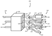
- FIG. 1 an embodiment of a generator connection system 100 is shown that allows utility personnel to quickly connect an auxiliary power source to the distribution system and isolate the distribution system from the rest of the electrical utility network.
- the system 100 is typically located in a subterranean location and accessed by utility personnel via a manhole.
- the system 100 is connected to a low voltage distribution network, on which the customers are served from a three-phase, circuit.
- the system 100 may be connected to three input conductors 108 , 111 , 112 that are connected to receive electrical power from the utility network.
- the system may further be connected to three output conductors 104 , 107 , 110 that are connected to the electrical loads (e.g. utility customers).
- the system 100 is disposed between a first portion 102 of a secondary distribution network and a second portion 106 of the secondary distribution network.
- the system 100 includes a switch 114 disposed between the conductor 108 and a t-type connector 116 .
- the switch 114 is configured to be actuated between a closed position and an open position.
- the switch 114 When in the open position, the switch 114 electrically isolates the input conductors 108 , 111 , 112 from the output conductors 104 , 107 , 110 .
- an auxiliary electrical generator may be added to provide electrical power to the second portion 106 .
- the connector 116 is coupled to the switch 114 by a conductor 118 .
- a conductor 120 connects with a crab joint 122 .
- the crab joint 122 is a commonly used connection arrangement that typically includes a fusable link.
- a crab joint typically includes a central hub (referred to as the “busbar”) with multiple fusible connections (referred to as “limiters”) to a number of cables constituting part of the network. The limiters act to protect the cables and other equipment connected to them in case of failure of any of the cables in the network.
- the opposite side of the crab joint 122 connects with the conductor 104 .
- a conductor 121 connects the switch 114 to the crab joint 122 opposite the conductor 105 .
- the conductor 112 is similarly connected to a switch 124 and a t-type connector 126 .
- the side of the connector 126 opposite the switch 124 is connected by a conductor 128 to the crab joint 122 .
- the crab joint 122 also connects the conductor 128 with the conductor 110 .
- the conductor 111 is electrically connected to the conductor 107 via a switch 121 and a connector 125 that electrically connects the switch 124 with the crab joint 122 .
- the t-type connector 116 includes a body 130 having an elastomeric outer layer 132 .
- the body 130 may be formed from a single solid electrically conductive material, such as copper for example.
- the layer 132 encases the body and in an embodiment provides a water-resistant or a water-proof layer over the body 130 .
- the layer 132 is made from a rubber material.
- the body 130 includes first arm 134 having a first opening 136 formed on an end 138 .
- the first opening 136 may be a cylindrical bore that is sized to receive the conductor 108 .
- the conductor 108 and opening 136 are coupled together via a compression joint.
- the body 130 further includes a second arm 140 having a second opening 142 formed on an end 144 . Similar to the opening 136 , the opening 142 may be a cylindrical bore sized to receive the conductor 120 .
- the arms 134 , 140 are aligned such that the axis of openings 136 , 142 are collinear.
- the body 130 further includes a third arm 146 that extends perpendicular to the arms 134 , 140 .
- a fourth arm 148 extends from the third arm 146 .
- the fourth arm 148 extends generally parallel with the first arm 134 .
- the fourth arm 148 may extend on an angle relative to the arms 134 , 140 , 146 .
- the fourth arm 148 may extend parallel with the second arm 140 .
- the fourth arm 148 includes an opening 150 that extends from an end 152 .
- the opening 150 may be a cylindrical bore that is sized to receive a generator conductor 154 .
- the body 130 is configured to operate at 600 V, 600 Amp continuous rating with a 50 KA short circuit rating.
- the generator conductor 154 is a 500 kCMIL welding cable that has a length of 1-5 feet.
- the conductor 154 is insulated with a suitable material that allows the cable to be electrically insulated and submersible.
- a generator plug 156 is a camlock type connector that allows utility personnel to quickly connect an auxiliary electrical generator to the generator conductor 154 .
- a second generator conductor 158 having a generator plug 160 is coupled to the connector 126 .
- a third generator conductor 159 having a generator plug 162 is coupled to connector 125 .
- the generator plugs 156 , 160 , 162 are configured to be submersible when installed.
- the plug 156 includes a body 170 that is coupled to the generator conductor 154 , such as with a compression coupling.
- the plug 156 has an end 172 that includes a connection means 174 , such as a camlock type connector for example, that is configured to couple with a compatible plug (not shown) connected to the auxiliary generator.
- the body 170 includes a shoulder 176 at the transition between the body 170 and the end 172 .
- the plug 156 is configured to be submersible.
- a cap member 178 is provided that has an opening 180 that has a diameter sized to be received on the end 172 as a press-fit.
- the end surface 182 engages a side surface 184 of the shoulder 176 when the cap 178 is installed on the end 172 .
- the cap 178 cooperates with the end 172 to prevent water from migrating to the connection means 174 .
- the cap 178 is coupled to a cable or tether 186 .
- the opposite end of the tether 186 is coupled to a collar 188 that is slidably coupled to the body 170 .
- the collar 188 , the tether 186 and the cap 178 are formed from a unitary or single piece of material.
- the switches 114 , 124 are configured to flow electrical power from the second portion 106 to the first portion 102 .
- the generator plugs 156 , 160 are disconnected from the auxiliary electrical generator.
- the electrical utility desires to power the first portion 102 from the auxiliary electrical generator instead of from the main distribution system, the utility personnel first access the system 100 , such as via a manhole cover for example.
- the switches 114 , 124 are actuated and the first portion 102 is isolated from the second portion 106 and electrical power is removed from the secondary distribution network. Cables with a plug compatible with the generator plugs 156 , 160 are connected between the auxiliary electrical generator and the generator conductors 154 , 158 .
- the auxiliary electrical generator is activated and electrical power flows to the first portion 102 via the connectors 116 , 126 to allow the auxiliary electrical generator to pick up the load of the secondary distribution network.
- the process is performed in reverse.
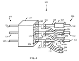
- FIG. 4 and FIG. 5 another embodiment is shown of a generator connection system 200 .
- the components of system 200 that are identical to those of system 100 will not be repeated here for brevity.
- the system 200 is similar to system 100 , except that connector 202 includes a fifth arm 204 that extends generally parallel to the fourth arm 148 .
- connector 202 includes a fifth arm 204 that extends generally parallel to the fourth arm 148 .
- the arrangement illustrated in FIG. 5 with the arms 148 , 204 extending from the same side as third arm 146 is for exemplary purposes and the claims should not be so limited.
- the arms 148 , 204 may be disposed on opposing sides of third arm 146 .
- the fifth arm 204 may extend from an end 218 of the body 130 opposite the conductors 206 , 208 . Further one or more of the arms 148 , 204 may extend on an angle relative to the conductors 206 , 208 . In still further embodiments, the arms 148 , 204 may extend from the end 218 in a Y-configuration. In an embodiment, the connector 202 has a 30 kV, 600 amp continuous rating with a 50 KA peak short circuit rating.
- the arms 148 , 204 are connected to generator conductors 210 , 212 for connecting to an electrical generator.
- the generator conductor 210 , 212 may be smaller or lower capacity than the embodiment using a single conductor, such as conductor 154 for example.
- the conductors 210 , 212 are made from a 250-350 kCMIL welding cable that has a length of 1-5 feet. In still other embodiments, the conductors 210 , 212 are made from 500 kCMIL welding cable.
- Each conductor 210 , 212 has a generator plug 214 , 216 connected to an end opposite the connector 202 .
- the generator plugs 214 , 216 are camlock type connectors that allow utility personnel to quickly connect an auxiliary electrical generator to the generator conductors 210 , 212 .
- FIG. 4 illustrates the connectors 116 , 126 as having a single generator conductor coupled thereto. It should be appreciated that the connectors 116 , 126 may also be configured in the same manner as connector 202 with two generator conductors. Further, the plugs 214 , 216 may be configured in the same manner as illustrated in FIG. 3 with a cap member 178 that prevents or reduces the risk of water migration into the plug.
Landscapes
- Engineering & Computer Science (AREA)
- Power Engineering (AREA)
- Cable Accessories (AREA)
- Business, Economics & Management (AREA)
- Emergency Management (AREA)
Abstract
Description
Claims (20)
Priority Applications (1)
| Application Number | Priority Date | Filing Date | Title |
|---|---|---|---|
| US15/598,448 US10424924B2 (en) | 2016-05-19 | 2017-05-18 | Utility grid generator connection |
Applications Claiming Priority (2)
| Application Number | Priority Date | Filing Date | Title |
|---|---|---|---|
| US201662338635P | 2016-05-19 | 2016-05-19 | |
| US15/598,448 US10424924B2 (en) | 2016-05-19 | 2017-05-18 | Utility grid generator connection |
Publications (2)
| Publication Number | Publication Date |
|---|---|
| US20170338655A1 US20170338655A1 (en) | 2017-11-23 |
| US10424924B2 true US10424924B2 (en) | 2019-09-24 |
Family
ID=60329143
Family Applications (1)
| Application Number | Title | Priority Date | Filing Date |
|---|---|---|---|
| US15/598,448 Active 2038-03-28 US10424924B2 (en) | 2016-05-19 | 2017-05-18 | Utility grid generator connection |
Country Status (1)
| Country | Link |
|---|---|
| US (1) | US10424924B2 (en) |
Citations (16)
| Publication number | Priority date | Publication date | Assignee | Title |
|---|---|---|---|---|
| US6381155B1 (en) * | 2000-05-23 | 2002-04-30 | Next Power Corporation | Method for clusterized power sharing conversion and regulation of the primary power source within a converting and regulating power supply, and system |
| US6679728B1 (en) * | 2002-12-27 | 2004-01-20 | Insert Enterprise Co., Ltd. | Mini BNC connector |
| US7259481B2 (en) * | 2003-02-28 | 2007-08-21 | Kohler Co. | Automatic transfer switch capable of receiving input power having voltage within a wide range |
| US20090249960A1 (en) * | 2007-10-12 | 2009-10-08 | Lassota Zbigniew G | Electrically powered beverage brewer and method of making and inventorying same |
| US20100210126A1 (en) | 2007-10-11 | 2010-08-19 | Everett Joseph Mcneill | Dual source connector system |
| US8152542B2 (en) | 2007-03-23 | 2012-04-10 | Pantrol, Inc. | Electrical connector enclosure |
| US8174149B2 (en) * | 2007-03-14 | 2012-05-08 | Zonit Structured Solutions, Llc | Auto-switching duplex module |
| US8288890B2 (en) | 2009-01-02 | 2012-10-16 | Young Gordon W | Simple emergency power connection switch |
| US8292658B2 (en) | 2010-04-28 | 2012-10-23 | William Dewey Sullivan, JR. | Apparatus and method for connecting emergency power |
| US20140218010A1 (en) * | 2011-11-02 | 2014-08-07 | Infinite Invention Llc | Meter collar for plug-in connection of distributed power generation |
| US20140352998A1 (en) | 2011-11-23 | 2014-12-04 | Phoenix Contact Gmbh & Co. Kg | Generator Connection Box for Photovoltaic Installations |
| US20150035358A1 (en) * | 2013-08-05 | 2015-02-05 | Ragingwire Data Centers, Inc. | Electrical power management system and method |
| US9281716B2 (en) * | 2011-12-20 | 2016-03-08 | Kohler Co. | Generator controller configured for preventing automatic transfer switch from supplying power to the selected load |
| US20160094152A1 (en) * | 2014-09-29 | 2016-03-31 | U.S. Army Research Laboratory Attn: Rdrl-Loc-I | Scalable universal power supply and power converter |
| US20160181767A1 (en) * | 2014-12-19 | 2016-06-23 | Robert Louis Stone | Electrical enclosure voltage protection system |
| US20160195435A1 (en) * | 2014-12-03 | 2016-07-07 | Heidelberger Druckmaschinen Ag | Device for measuring the temperature in a plug connector by using a superimposed test frequency |
-
2017
- 2017-05-18 US US15/598,448 patent/US10424924B2/en active Active
Patent Citations (16)
| Publication number | Priority date | Publication date | Assignee | Title |
|---|---|---|---|---|
| US6381155B1 (en) * | 2000-05-23 | 2002-04-30 | Next Power Corporation | Method for clusterized power sharing conversion and regulation of the primary power source within a converting and regulating power supply, and system |
| US6679728B1 (en) * | 2002-12-27 | 2004-01-20 | Insert Enterprise Co., Ltd. | Mini BNC connector |
| US7259481B2 (en) * | 2003-02-28 | 2007-08-21 | Kohler Co. | Automatic transfer switch capable of receiving input power having voltage within a wide range |
| US8174149B2 (en) * | 2007-03-14 | 2012-05-08 | Zonit Structured Solutions, Llc | Auto-switching duplex module |
| US8152542B2 (en) | 2007-03-23 | 2012-04-10 | Pantrol, Inc. | Electrical connector enclosure |
| US20100210126A1 (en) | 2007-10-11 | 2010-08-19 | Everett Joseph Mcneill | Dual source connector system |
| US20090249960A1 (en) * | 2007-10-12 | 2009-10-08 | Lassota Zbigniew G | Electrically powered beverage brewer and method of making and inventorying same |
| US8288890B2 (en) | 2009-01-02 | 2012-10-16 | Young Gordon W | Simple emergency power connection switch |
| US8292658B2 (en) | 2010-04-28 | 2012-10-23 | William Dewey Sullivan, JR. | Apparatus and method for connecting emergency power |
| US20140218010A1 (en) * | 2011-11-02 | 2014-08-07 | Infinite Invention Llc | Meter collar for plug-in connection of distributed power generation |
| US20140352998A1 (en) | 2011-11-23 | 2014-12-04 | Phoenix Contact Gmbh & Co. Kg | Generator Connection Box for Photovoltaic Installations |
| US9281716B2 (en) * | 2011-12-20 | 2016-03-08 | Kohler Co. | Generator controller configured for preventing automatic transfer switch from supplying power to the selected load |
| US20150035358A1 (en) * | 2013-08-05 | 2015-02-05 | Ragingwire Data Centers, Inc. | Electrical power management system and method |
| US20160094152A1 (en) * | 2014-09-29 | 2016-03-31 | U.S. Army Research Laboratory Attn: Rdrl-Loc-I | Scalable universal power supply and power converter |
| US20160195435A1 (en) * | 2014-12-03 | 2016-07-07 | Heidelberger Druckmaschinen Ag | Device for measuring the temperature in a plug connector by using a superimposed test frequency |
| US20160181767A1 (en) * | 2014-12-19 | 2016-06-23 | Robert Louis Stone | Electrical enclosure voltage protection system |
Also Published As
| Publication number | Publication date |
|---|---|
| US20170338655A1 (en) | 2017-11-23 |
Similar Documents
| Publication | Publication Date | Title |
|---|---|---|
| Hsieh et al. | Adaptive relay setting for distribution systems considering operation scenarios of wind generators | |
| EP2633597B1 (en) | Voltage balancing of symmetric hvdc monopole transmission lines after earth faults | |
| US10666035B2 (en) | Mounting system for sensors on electrical power lines | |
| Magg et al. | Connecting networks with VSC HVDC in Africa: Caprivi Link interconnector | |
| US10424924B2 (en) | Utility grid generator connection | |
| Bassi et al. | Evaluation of currents and charges in low-voltage surge arresters due to lightning strikes | |
| US12609221B2 (en) | Plug mounted surge arrester | |
| Siahaan et al. | Fault current limitation roadmap to anticipate the problem of high fault currents in Indonesian Java-Bali Power System | |
| CN210838949U (en) | Low-voltage quick access communication device and power supply network | |
| Kehl et al. | Cross-bonding for MV cable systems: advantages and impact on accessories design | |
| Jardini et al. | Overvoltage assessment of point-to-point vsc-based hvdc systems | |
| DSouza et al. | Power System Design for a Large, Dynamic Natural Gas Field: Improving the Field Production Profile | |
| KR102805350B1 (en) | Mobile transformer connection device for 3 phase transformer | |
| US11962132B2 (en) | Support bracket for transformer switch utilizing existing transformer connection points | |
| CN109921405A (en) | A kind of earthing method of medium voltage network neutral point | |
| US20240348018A1 (en) | System for electrically isolating a bus bar in a bus bar vault | |
| KR20210115343A (en) | An electric power supply method of the control unit for pad mounted type switchgear for underground line | |
| Konusarov et al. | Grounding systems for power supply facilities | |
| Bucarelli et al. | Investigating the impact of short-circuit faults in different neutral configurations: a real case study | |
| Kabir et al. | A Study on Bangladesh Power System Fault Level Management | |
| Zoroofi et al. | Commutation failure propagation in multi-infeed HVDC systems | |
| Last et al. | The Underground HV DC Link for the Transmission of Bulk Power from the Thames Estuary to the Centre of London | |
| D'Souza et al. | Power system design for a large dynamic natural gas field | |
| McMILLAN et al. | Integration of an 88 km 220 kV AC cable into the Victorian Electricity Network in Australia | |
| Lonare et al. | Installation of 11kV/440V Distribution Substation |
Legal Events
| Date | Code | Title | Description |
|---|---|---|---|
| AS | Assignment |
Owner name: CONSOLIDATED EDISON COMPANY OF NEW YORK, INC., NEW Free format text: ASSIGNMENT OF ASSIGNORS INTEREST;ASSIGNORS:ZOLOTOV, KIRILL;FANEK, BAETH;REEL/FRAME:042422/0035 Effective date: 20170518 |
|
| STPP | Information on status: patent application and granting procedure in general |
Free format text: DOCKETED NEW CASE - READY FOR EXAMINATION |
|
| STPP | Information on status: patent application and granting procedure in general |
Free format text: NOTICE OF ALLOWANCE MAILED -- APPLICATION RECEIVED IN OFFICE OF PUBLICATIONS |
|
| STPP | Information on status: patent application and granting procedure in general |
Free format text: PUBLICATIONS -- ISSUE FEE PAYMENT VERIFIED |
|
| STCF | Information on status: patent grant |
Free format text: PATENTED CASE |
|
| FEPP | Fee payment procedure |
Free format text: MAINTENANCE FEE REMINDER MAILED (ORIGINAL EVENT CODE: REM.); ENTITY STATUS OF PATENT OWNER: LARGE ENTITY |
|
| FEPP | Fee payment procedure |
Free format text: SURCHARGE FOR LATE PAYMENT, LARGE ENTITY (ORIGINAL EVENT CODE: M1554); ENTITY STATUS OF PATENT OWNER: LARGE ENTITY |
|
| MAFP | Maintenance fee payment |
Free format text: PAYMENT OF MAINTENANCE FEE, 4TH YEAR, LARGE ENTITY (ORIGINAL EVENT CODE: M1551); ENTITY STATUS OF PATENT OWNER: LARGE ENTITY Year of fee payment: 4 |