EP2781905B1 - Verfahren und vorrichtung zur bestimmung der permeationsrate von barrierematerialien - Google Patents
Verfahren und vorrichtung zur bestimmung der permeationsrate von barrierematerialien Download PDFInfo
- Publication number
- EP2781905B1 EP2781905B1 EP14152470.2A EP14152470A EP2781905B1 EP 2781905 B1 EP2781905 B1 EP 2781905B1 EP 14152470 A EP14152470 A EP 14152470A EP 2781905 B1 EP2781905 B1 EP 2781905B1
- Authority
- EP
- European Patent Office
- Prior art keywords
- concentration
- measurement
- time
- permeate
- predefinable
- Prior art date
- Legal status (The legal status is an assumption and is not a legal conclusion. Google has not performed a legal analysis and makes no representation as to the accuracy of the status listed.)
- Active
Links
Images


Classifications
-
- G—PHYSICS
- G01—MEASURING; TESTING
- G01N—INVESTIGATING OR ANALYSING MATERIALS BY DETERMINING THEIR CHEMICAL OR PHYSICAL PROPERTIES
- G01N15/00—Investigating characteristics of particles; Investigating permeability, pore-volume or surface-area of porous materials
- G01N15/08—Investigating permeability, pore-volume, or surface area of porous materials
- G01N15/082—Investigating permeability by forcing a fluid through a sample
- G01N15/0826—Investigating permeability by forcing a fluid through a sample and measuring fluid flow rate, i.e. permeation rate or pressure change
-
- G—PHYSICS
- G01—MEASURING; TESTING
- G01N—INVESTIGATING OR ANALYSING MATERIALS BY DETERMINING THEIR CHEMICAL OR PHYSICAL PROPERTIES
- G01N15/00—Investigating characteristics of particles; Investigating permeability, pore-volume or surface-area of porous materials
- G01N15/08—Investigating permeability, pore-volume, or surface area of porous materials
- G01N15/0806—Details, e.g. sample holders, mounting samples for testing
-
- G—PHYSICS
- G01—MEASURING; TESTING
- G01N—INVESTIGATING OR ANALYSING MATERIALS BY DETERMINING THEIR CHEMICAL OR PHYSICAL PROPERTIES
- G01N15/00—Investigating characteristics of particles; Investigating permeability, pore-volume or surface-area of porous materials
- G01N15/08—Investigating permeability, pore-volume, or surface area of porous materials
- G01N2015/086—Investigating permeability, pore-volume, or surface area of porous materials of films, membranes or pellicules
-
- G—PHYSICS
- G01—MEASURING; TESTING
- G01N—INVESTIGATING OR ANALYSING MATERIALS BY DETERMINING THEIR CHEMICAL OR PHYSICAL PROPERTIES
- G01N21/00—Investigating or analysing materials by the use of optical means, i.e. using sub-millimetre waves, infrared, visible or ultraviolet light
- G01N21/17—Systems in which incident light is modified in accordance with the properties of the material investigated
- G01N21/25—Colour; Spectral properties, i.e. comparison of effect of material on the light at two or more different wavelengths or wavelength bands
- G01N21/31—Investigating relative effect of material at wavelengths characteristic of specific elements or molecules, e.g. atomic absorption spectrometry
- G01N21/39—Investigating relative effect of material at wavelengths characteristic of specific elements or molecules, e.g. atomic absorption spectrometry using tunable lasers
- G01N2021/396—Type of laser source
- G01N2021/399—Diode laser
-
- G—PHYSICS
- G01—MEASURING; TESTING
- G01N—INVESTIGATING OR ANALYSING MATERIALS BY DETERMINING THEIR CHEMICAL OR PHYSICAL PROPERTIES
- G01N21/00—Investigating or analysing materials by the use of optical means, i.e. using sub-millimetre waves, infrared, visible or ultraviolet light
- G01N21/01—Arrangements or apparatus for facilitating the optical investigation
- G01N21/03—Cuvette constructions
- G01N21/031—Multipass arrangements
-
- G—PHYSICS
- G01—MEASURING; TESTING
- G01N—INVESTIGATING OR ANALYSING MATERIALS BY DETERMINING THEIR CHEMICAL OR PHYSICAL PROPERTIES
- G01N21/00—Investigating or analysing materials by the use of optical means, i.e. using sub-millimetre waves, infrared, visible or ultraviolet light
- G01N21/17—Systems in which incident light is modified in accordance with the properties of the material investigated
- G01N21/25—Colour; Spectral properties, i.e. comparison of effect of material on the light at two or more different wavelengths or wavelength bands
- G01N21/31—Investigating relative effect of material at wavelengths characteristic of specific elements or molecules, e.g. atomic absorption spectrometry
- G01N21/33—Investigating relative effect of material at wavelengths characteristic of specific elements or molecules, e.g. atomic absorption spectrometry using ultraviolet light
-
- G—PHYSICS
- G01—MEASURING; TESTING
- G01N—INVESTIGATING OR ANALYSING MATERIALS BY DETERMINING THEIR CHEMICAL OR PHYSICAL PROPERTIES
- G01N21/00—Investigating or analysing materials by the use of optical means, i.e. using sub-millimetre waves, infrared, visible or ultraviolet light
- G01N21/17—Systems in which incident light is modified in accordance with the properties of the material investigated
- G01N21/25—Colour; Spectral properties, i.e. comparison of effect of material on the light at two or more different wavelengths or wavelength bands
- G01N21/31—Investigating relative effect of material at wavelengths characteristic of specific elements or molecules, e.g. atomic absorption spectrometry
- G01N21/35—Investigating relative effect of material at wavelengths characteristic of specific elements or molecules, e.g. atomic absorption spectrometry using infrared light
- G01N21/3504—Investigating relative effect of material at wavelengths characteristic of specific elements or molecules, e.g. atomic absorption spectrometry using infrared light for analysing gases, e.g. multi-gas analysis
-
- G—PHYSICS
- G01—MEASURING; TESTING
- G01N—INVESTIGATING OR ANALYSING MATERIALS BY DETERMINING THEIR CHEMICAL OR PHYSICAL PROPERTIES
- G01N21/00—Investigating or analysing materials by the use of optical means, i.e. using sub-millimetre waves, infrared, visible or ultraviolet light
- G01N21/17—Systems in which incident light is modified in accordance with the properties of the material investigated
- G01N21/25—Colour; Spectral properties, i.e. comparison of effect of material on the light at two or more different wavelengths or wavelength bands
- G01N21/31—Investigating relative effect of material at wavelengths characteristic of specific elements or molecules, e.g. atomic absorption spectrometry
- G01N21/35—Investigating relative effect of material at wavelengths characteristic of specific elements or molecules, e.g. atomic absorption spectrometry using infrared light
- G01N21/3581—Investigating relative effect of material at wavelengths characteristic of specific elements or molecules, e.g. atomic absorption spectrometry using infrared light using far infrared light; using Terahertz radiation
-
- G—PHYSICS
- G01—MEASURING; TESTING
- G01N—INVESTIGATING OR ANALYSING MATERIALS BY DETERMINING THEIR CHEMICAL OR PHYSICAL PROPERTIES
- G01N21/00—Investigating or analysing materials by the use of optical means, i.e. using sub-millimetre waves, infrared, visible or ultraviolet light
- G01N21/17—Systems in which incident light is modified in accordance with the properties of the material investigated
- G01N21/25—Colour; Spectral properties, i.e. comparison of effect of material on the light at two or more different wavelengths or wavelength bands
- G01N21/31—Investigating relative effect of material at wavelengths characteristic of specific elements or molecules, e.g. atomic absorption spectrometry
- G01N21/35—Investigating relative effect of material at wavelengths characteristic of specific elements or molecules, e.g. atomic absorption spectrometry using infrared light
- G01N21/359—Investigating relative effect of material at wavelengths characteristic of specific elements or molecules, e.g. atomic absorption spectrometry using infrared light using near infrared light
Definitions
- the invention relates to a method for determining the permeation rate of barrier materials.
- barrier materials with different permeation rates find an ever wider area of application, for example for the packaging of foods or medicaments or for the encapsulation of electronic components.
- organic electronics such as organic LEDs, organic photovoltaics or vacuum insulation panels (VIP)
- VIP vacuum insulation panels
- Barrier materials are required with the lowest permeation rates, since the quality and life of these components depends on the moisture protection.
- measurement techniques are required to reliably and easily determine permeation rates in the range of 10 -5 to 10 -6 gm -2 d -1 .
- measuring methods are known in which a test gas from a first chamber is permeated by a barrier material into a second closed chamber and the increase in the permeate concentration in the gas phase of the closed chamber is measured over a certain time.
- this method is subject to errors due to different influences.
- the temporal increase of the permeate concentration is neither constant nor proportional to the permeation rate.
- Such errors are particularly at very low permeate concentrations to be determined, since the molecules of the permeate interact with the solid surfaces within the closed chambers. Especially when determining very low permeate concentrations, ignoring these effects inevitably leads to strongly faulty measurement results. Therefore, measuring methods are required with which in particular condensable gases can be determined unaffected by their adsorption and desorption properties.
- a humidity sensor measures the increase in relative humidity from, for example, 9.9% to 10.1% in a closed measuring chamber. Subsequently, the measuring chamber is rinsed to a lower limit of the measuring range and a certain number of sub-drying cycles are carried out for conditioning the measuring cell before a new measuring cycle is started. If the increases of several measuring cycles coincide, it can be assumed that they are stationary and the permeation rate through the barrier element can be determined. However, the measuring range of the water vapor permeability is in a range between 0.03 - 10000 gm -2 d -1 and is thus too many orders of magnitude too high to be able to determine the lowest permeation rates.
- measuring methods such as, for example, the calcium mirror test or radiometric methods, require complex sample preparation and, in principle, long measurement times.
- the US Pat. No. 6,964,191 B1 concerns possibilities for the determination of permeation and permeatorption.
- Packaging or containers within a sealed chamber can be examined.
- a sensor is used to determine the permeate concentration in the chamber after permeation from a package or container. In this case, a determination of the time takes place until reaching a predetermined limit value.
- a concentration of at least one permeate which is present as test gas in a test gas chamber with a constant concentration in a measuring chamber which has at least two shut-off elements for opening and closing is determined by a between the test gas chamber and the measuring chamber arranged barrier element, which has a known permeable surface (A), permeating into the measuring chamber.
- the measuring chamber is rinsed in a first measurement variant from a predefinable upper switching concentration (cvA) or in a second measuring variant after reaching a predeterminable enrichment time (tvA) by opening the shut-off elements with a constant permeate-free purge gas volume flow ( V ⁇ ) , wherein the permeate concentration (c) in the open measuring chamber as a result of rinsing sinks.
- the course of the decreasing permeate concentration (c) in the first measurement variant is determined until a predeterminable lower switchover concentration (cvS) is reached, wherein in addition the purging time (tS) is determined.
- the course of the decreasing permeate concentration (c) is determined until a predefinable purge time (tvS) is reached.
- the measuring chamber is closed by closing the shut-off elements in a method step (ii), in the first measuring variant when the predefinable lower switching concentration (cvS) or in the second measuring variant is reached when the predefined rinsing time (tvS) is reached, the permeate concentration in the closed Measuring chamber as a result of permeation increases.
- an enrichment time (tA) is determined until the predefinable upper switchover concentration (cvA) is reached.
- t total for the first measurement variant is the sum of the purge time (tS) and the enrichment time (tA) and for the second measurement variant the sum of the predefinable purge time (tvS) and the predeterminable enrichment time (tvA)
- M is the molar mass of
- Permeate is the proportion of the test gas that passes through the barrier element into the measuring chamber during permeation from the test gas chamber, in which a constant concentration of the test gas is present.
- the predeterminable upper and lower switching concentration represent the maximum or minimum achievable concentrations of the permeate in the measuring chamber.
- the purge time (tS) is understood to mean the time required for the settable purge gas volume flow ( V ⁇ ) to reach the permeate concentration (c) in the measurement chamber, starting from the predefinable upper switching concentration (cvA), up to the predeterminable lower switching concentration ( cvS).
- the enrichment time (tA) is the time that is necessary when the measuring chamber is closed until, starting from the predefinable lower switching concentration (cvS), the permeate concentration (c) in the measuring chamber exceeds the value of the predefinable upper switching concentration (cvA) as a result of the permeation reaches the barrier element. This means that the opening of the shut-off elements is carried out at the predefinable upper switching concentration (cvA) and the closing of the shut-off elements at the specifiable lower switching concentration (cvS).
- the measuring chamber in step (i) is limited in time for a predetermined rinsing time (tvS) with the permeate Spülgasvolumenstrom ( V ⁇ ) rinsed and closed in step (ii) for a predetermined enrichment time (tvA) ,
- tvS predetermined rinsing time
- V ⁇ permeate Spülgasvolumenstrom
- tvA predetermined enrichment time
- an upper switchover concentration value (cA) is established in the second measurement variant and a lower switchover concentration value (cS) at the end of the predefinable purge time (tvS).
- the upper and lower switching concentration (cvA, cvS) are specified
- the purge time (tvS) and the enrichment time (tvA) are specified.
- the method can be carried out beginning with method step (i) or with method step (ii).
- a change from the method step (i) to the method step (ii) and vice versa can after reaching the predetermined lower switching concentration (cvS) or the predetermined upper switching concentration (cvA) or after reaching the predetermined rinsing time (tvS) or the predetermined enrichment time ( tvA).
- the permeation rate (P) can be determined in each case from at least one measuring cycle consisting of at least one process step (i) and at least one process step (ii).
- the measuring cycle can consequently also be formed from a plurality of method steps (i) and (ii).
- the permeate concentration increases as a result of the permeation through the barrier element .
- One portion of the permeate adsorbs to the inner solid surfaces of the measuring chamber and another portion remains in the gas phase.
- An equilibrium state between the permeate adsorption and desorption can be established in the closed measuring chamber.
- GGW state of equilibrium
- a stationary state can be understood as the state which is reached when a constant permeation rate has been established by the barrier element. It should be ensured that a constant concentration of the test gas is present in the test gas chamber.
- the permeate concentration of the gas phase of the measuring chamber initially decreases faster than the concentration of adsorbed on the solid surfaces Permeate, which removes the GGW in the measuring chamber.
- the permeation concentration, ie the adsorbed fraction and the fraction in the gas phase follows a transient isothermal characteristic curve, the course of which from its starting point on the system isotherm characteristic, ie, for example, starting from the predefinable upper switching concentration (cvA) and the Spülgasvolumenstrom ( V ⁇ ) depends.
- the interruption of the flushing gas volume flow ( V ⁇ ) caused in step (ii) by the closure of the shut-off elements causes an increase in the permeation concentration in the gas phase due to the permeation through the barrier element .
- the permeate concentration of the gas phase increases continuously. Until reaching a point of intersection with the isotherm characteristic, the proportion of adsorbed gas is also slightly reduced due to desorption processes. When the intersection with the isotherm characteristic curve is reached, the permeate concentration increases along the isothermal characteristic curve. This means that the GGW is almost restored.
- the permeation rate should preferably be determined only when the stationary state has set. This is the case when a stable concentration gradient of the permeator has formed in the barrier or barrier film, i. the moisture is broken and the permeation rate is constant. Due to the small concentration change in the measuring chamber, which is only a few ppm, the concentration difference to the test gas side remains virtually unaffected.
- a purge and enrichment step should be performed at least once be such that it can be assumed that the state of equilibrium (GGW) exists.
- the measuring cycle can also be repeated until the total cycle time resulting from the sum of the enrichment time (tA) and the rinsing time (tS) coincides with that of the immediately preceding measuring cycle or by a maximum the double measurement uncertainty deviates.
- the presence of the stationary state can be checked with the second measuring variant by repeating the measuring cycle until the lower switching concentration value (cS) coincides with that of the immediately preceding measuring cycle or deviates from it by at most twice the measurement uncertainty and at the same time the difference between the upper switching concentration value (cA) and the lower switching concentration value (cS) coincides with that of the immediately preceding measurement cycle or deviates by at most twice the measurement uncertainty.
- the measurement uncertainty refers to a parameter assigned to the measurement result, which characterizes the scattering of the measured values which can reasonably be assigned to the measured variable.
- a simple measurement uncertainty means a security probability of 68.3%
- a double measurement uncertainty means a security probability of 95.4%.
- the purging gas volume flow ( V ⁇ ) can be adjusted and should be the same during the process steps (i) of successive measurement cycles, which are carried out beginning with process step (ii).
- a repeated loop between the respective switching concentrations (cvA, cVS) and the switching concentration values (cV, cS) can be set by repeating the measuring cycles.
- the method steps (i) and method steps (ii) used to calculate the permeation rate (P) need not necessarily follow one another but can be integrated via a plurality of method steps (i), the integration correspondingly referring to the total purging time and the total time ( t total ) corresponds to the sum of all considered rinsing and enrichment times.
- the measuring chamber When carrying out a first measuring cycle consisting of method steps (i) and (ii), the measuring chamber, preferably at a measuring cycle beginning with method step (i), should be preconditioned at least once by opening the shut-off elements, preferably until the predefinable lower switching concentration (cvS) or the predefinable rinsing time (tvS) is reached, pre-rinsed with the permeate-free purge gas volume flow ( V ⁇ ) and then closed again the measuring chamber by closing the shut-off.
- the starting point of the preconditioning of the measuring chamber can lie on the isotherm characteristic whose permeation concentration is greater than the upper switching concentration (cvA).
- the starting point of the preconditioning of the measuring chamber can also be in the range of atmospheric conditions.
- the measuring chamber should be isolated from the ambient atmosphere and the temperature kept constant.
- the described method can preferably be carried out at a temperature in the range between 10 ° C. and 80 ° C. for all condensable gases and vapors, as test gas or permeate.
- the preferred test gas is water vapor, it must be ensured that a permeat cartier Spülgasvolumenstrom (V) and in the case of steam as the test gas, a dry Spülgasvolumenstrom (V) is used.
- a higher accuracy of the determination of the permeation rate can be achieved by determining the mean value from the respectively determined permeation rates.
- an approximate value of the permeation rate to be expected can be estimated in a subsequent measuring cycle on the basis of which, for example, the predefinable upper switching concentration (cvA) and / or the predefinable lower switching concentration (cvS) are limited for subsequent measuring cycles can / can.
- the accuracy of the permeation rate determination can be increased if the difference between the predeterminable upper switchover concentration (cvA) and the predefinable lower switchover concentration (cvS) is increased or in the second measurement variant the predefinable wash time (tvS) and / or the predeterminable enrichment time (tvA) is extended.
- V ⁇ purge gas volume flow
- An increase in the measurement accuracy can also be achieved by optimizing the operating point, which lies within a range in which the gas concentration measurement has its highest sensitivity.
- An optimization of the operating point is to be understood as an adaptation of the predefinable upper and lower switching concentration (cvA, cvS) or an adaptation of the predeterminable flushing and enrichment times (tvS, tvA).
- a noninvasive, preferably optical and / or capacitive measuring method should be used which does not consume and / or change the permeates. It should be possible to determine a permeation concentration in a range from 0.01 ppm to 1000 ppm using the measurement method mentioned.
- a laser-based measuring method particularly preferably a laser diode spectroscopy method can be used in which a laser beam is emitted with an emission wavelength tuned preferably to an absorption line of the permeate to be detected. There is the possibility that the laser is simply passed through the measuring chamber.
- the measuring chamber can also be designed as a multiple reflection measuring cell, in which a laser is repeatedly passed through the gas phase of the measuring chamber, for example deflected by a plurality of mirrors.
- the source of such a laser may be disposed within the measuring chamber or outside, wherein the laser beam is coupled through windows in the measuring chamber.
- a laser source can be used which emits a laser beam with several different wavelengths. Also advantageous are those laser sources in which the wavelength of the emitted laser beam, preferably in operation can be changed. It is also possible to use a plurality of laser sources, wherein a plurality of laser beams with mutually different wavelengths are emitted.
- the detection of the permeate concentration can also be carried out with at least one gas sensor specific for the permeate, which is arranged inside the measuring cell.
- the use of multiple gas sensors has the advantage that several different permeates can be determined simultaneously.
- Multi-channel gas sensors for example, a UV, VIS, NIR, MIR, quantum cascade laser or a terahertz spectrometer with the also several permeates can be determined simultaneously.
- a non-specific pressure sensor can be used in conjunction with a vacuum pump, wherein the purge gas volume flow is replaced by a pump flow rate.
- the pump volume flow can be determined, for example, via pressure drop measurement over a diaphragm.
- the permeate is the dominant species in the pumped volume flow, so that the pumped volume flow can be considered simplified as a permeate volume flow.
- the predefinable upper switching concentration (cvA) and the predefinable lower switching concentration (cvS) can be selected such that they lie in an optimum measuring range or working range for the measuring method or gas sensor used.
- the switching concentrations may preferably be chosen so that they do not fall below a lower permeation concentration limit at 0.01 ppm and do not exceed an upper permeation concentration limit at 1000 ppm.
- 100 ppm should be chosen for the predefinable upper switching concentration (cvA).
- the predefinable switching concentrations (cvA, cvS) can be set in an optimum measuring range or working range for the sensor (s) used, a particularly high accuracy of the permeation measurement can be achieved, which is higher than the accuracy of the conventional carrier gas-based Permeation measurement at the detection limit of the sensor used may be, or makes a determination of the permeation rate in comparison to a classic carrier gas-based permeation only possible.
- An apparatus for carrying out the method according to the invention has a measuring chamber with at least two shut-off elements for opening and closing. Furthermore, the device comprises a detection unit, with which a concentration of at least one permeate can be determined, which is present as a test gas with a constant concentration in a test gas chamber, by a arranged between the test gas chamber and the measuring chamber barrier element having a known permeable surface (A) in the Measuring chamber permeates, wherein the measuring chamber from reaching a predetermined upper switching concentration (cvA) or from reaching a predetermined enrichment time (tvA), by opening the shut-off with a constant scholar purge gas volume flow ( V ⁇ ) is flushed, as a result, the permeate concentration (c) in the measuring chamber decreases and the course of the permeate concentration (c) and upon specification of the upper switching concentration (cvA) the purge time (tS) until reaching the predetermined lower switching concentration (cvS) can be determined, and upon reaching a predetermined lower switching concentration (
- the proposed method can easily be carried out without elaborate sample preparation under the conditions described above, i. the non-invasive sensor is located in the measuring chamber, to be used with other already existing two-chamber measuring systems.
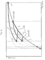
- FIG. 1a The illustrated state diagram schematically describes the relationship between the concentration of the adsorbed on the solid surfaces permeate and the permeate concentration in the gas phase during the preconditioning of the measuring chamber and the method steps (i) and (ii).
- the system isotherm characteristic characterized by the reference numeral 7 describes the function of the equilibrium state from the permeate concentration in the gas phase to the concentration of the permeates adsorbed on the solid surfaces in the measuring chamber 8.7.
- the specific adsorption behavior of each in the Contact with the permeate of standing material such as the cell wall material, the materials of the optical elements (windows, mirrors, fixation), sealing materials and the sample, ie the barrier material itself, is taken into account.
- the reference numeral 1 is in the FIG. 1a the course of concentration during the flushing within the preconditioning of the measuring chamber 8.7 is shown, which follows due to the flushing of a transient isothermal characteristic curve. Furthermore, the curve indicated by the reference numeral 2 shows the increase of the permeate concentration in the gas phase without a significant change in the concentration of the adsorbed permeate, immediately after closing the measuring chamber 8.7 in point 1.2.
- the concentration profile of the permeate follows the system isotherm characteristic curve 7, the starting point of a method step (i) being determined after a freely selectable time.
- an upper switchover concentration value cA is achieved, which is shown in brackets in FIG. 1a.
- the curve that is marked describes the change in concentration of the permeate in the measuring chamber 8.7, which is caused by the purge gas volume flow ( V ⁇ ) when the measuring chamber 8.7 is open during method step (i) until the predeterminable lower switching concentration cvS is reached in the first measuring variant or in the second measuring variant a predeterminable rinsing time tvS is reached, whereby at the end of the predefinable rinsing time tvS the in the Fig. 1a in brackets set lower switching concentration value cS.
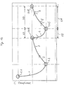
- FIG. 1b and Figure 1c show a schematic representation of a Permeatengaskonzentrations time course in a measuring chamber 8.7 in the first and in the second measurement variant.
- the course curve represented by the reference symbols 1, 2, and 3 designates a change in concentration of a permeate occurring in the gas phase of the measuring chamber 8.7 during a preconditioning of the measuring chamber 8.7.
- the reference numeral 4 describes the course of the permeate concentration in the measuring chamber 8.7 during a method step (i).
- Reference numerals 5 and 6 describe the profile of the permeate concentration in the measuring chamber 8.7 during a method step (ii).
- the test gas which is present in a constant concentration in the test gas chamber 8.3, permeates continuously from the test gas chamber 8.3 through a barrier element 8.5 arranged between the test gas chamber 8.3 and the knife chamber 8.7, which has a known permeable surface A, in the measuring chamber 8.7 and there causes the change in the permeate concentration.
- the curve section designated by the reference numeral 1 describes a flushing in the context of the preconditioning of the measuring chamber 8.7, in which the previously opened measuring chamber 8.7 starts from a flush-starting permeate concentration 1.1 with a permeate-free Purge gas volume flow ( V ⁇ ) is purged until a designated by the reference numeral 1.2 Spülend permeate concentration is reached.
- V ⁇ permeate-free Purge gas volume flow
- the permeate concentration in the measuring chamber 8.7 increases due to the continuous permeation of the test gas, as described with reference to the reference numerals 2 and 3 Curve course is traceable.
- the preconditioning of the measuring chamber 8.7 is carried out equally for both measuring variants.
- Fig. 1b which shows the first measurement variant, can be seen, reaches the curve described by the reference numerals 2 and 3, the predetermined upper switching concentration cvA at which the process step (i) begins.
- the curve section ends when a predefinable lower switching concentration cvS is reached, at which the purge gas volume flow ( V ⁇ ) is interrupted by the measuring chamber 8.7 being closed.
- Reference symbol tS denotes the rinsing time from reaching the predefinable upper switching concentration cvA until reaching the predefinable lower switching concentration cvS.
- Reference numerals 5 and 6 describe the curve of the permeation concentration during a process step (ii), in which, in the closed measuring chamber 8.7, the permeation concentration rises as a result of the permeation through the barrier element 8.5.
- Reference numeral tA describes the enrichment time, starting from the predefinable lower switching concentration cvS until reaching the predefinable upper switching concentration cvA.
- the starting point corresponds to the upper switching concentration value cA.
- the curve indicated by the reference numeral 4 which corresponds to a permeate concentration curve c, describes the reduction of the permeate concentration in the gas phase of the measuring chamber 8.7 during the process step (i), in which the measuring chamber 8.7 during the predetermined rinsing time tvS with a constant permeatelle purge gas volume flow ( V ⁇ ) is rinsed.
- the curve section ends when the predefinable flushing time tvS is reached, the lower switchover concentration value cS being reached.
- the purge gas volume flow ( V ⁇ ) is interrupted by the measuring chamber 8.7 is closed.
- the reference numerals 5 and 6 describe the curve of the permeate concentration during a process step (ii), in which the permeation concentration in the closed measuring chamber 8.7 increases as a result of the permeation through the barrier element 8.5 within the predefinable enrichment time tvA.
- method step (ii) ends after the predefinable enrichment time tvA has elapsed, the starting point of method step (i) being reached when the upper switchover concentration value cA is reached.
- the Figure 1d shows a representation of a determined with the first measurement variant Permeatengaskonzentrations time course of successive measurement cycles together with each determined per measurement cycle permeation rates, which are shown as hatched columns.
- the columns in which the permeation rates have each been determined with a measuring cycle started with method step (ii) are designated Pii-i.
- the left vertical axis has a scaling in ppm of the permeate concentration (water vapor concentration) in the measuring chamber 8.7, the right vertical axis having a scaling of the permeation rate in gm -2 d -1 .
- Permeatenkonzentrationen represented Permeatenkonzentrationen and each specific permeation rates are concrete results, which were determined with a device described below and an example of the inventive method described in detail below.
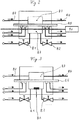
- the FIG. 2 shows a schematic sectional view of a device example for carrying out the method according to the invention.
- the apparatus comprises a measuring chamber 8.7 with two shut-off elements 8.1 and 8.2 for opening and closing, a test gas chamber 8.3 with constant test gas concentration, a arranged between the test gas chamber 8.3 and the measuring chamber 8.7 barrier element 8.5 with known area A and arranged on the measuring chamber 8.7 detection 8.6 for Detection of a test gas permeating the test gas chamber 8.3 through the barrier element 8.5 into the measuring chamber 8.7.
- the detection device is designed as a laser diode spectroscopy, wherein a laser beam is guided through the window not shown here through the measuring chamber 8.7.
- FIG. 3 shows a device as in Fig. 2 with the difference that the detection device 8.6 is designed as a capacitive gas sensor, which is arranged within the measuring chamber 8.7.
- shut-off 8.1 and 8.2 are designed as valves.
- ball valves gate valves or MFC (mass flow controller).
- the barrier element 8.5 may be, for example, materials such as metal foils, (metal) coated polymer films and their laminates or complex multilayer systems of polymers, metals and inorganic materials (oxides, nitrides, carbides, etc.).
- POLO® film consisting of a 75 ⁇ m PET Melinex 400CW substrate film and a layer composite of 180 nm zinc-tin oxide, 800 nm ORMOCER®, 180 nm zinc-tin oxide and 800 nm ORMOCER® was used as the barrier material, which was a Total thickness of 77 microns.
- the concentration of water vapor in the gas phase determined, which flows starting from the test gas chamber 8.3 in a supplied through the terminals 8.4 steam volume flow constant concentration, permeated by a between the test gas chamber 8.3 and the measuring chamber 8.7 arranged barrier element 8.5 in the measuring chamber 8.7.
- the water vapor concentration in the gas phase of the measuring chamber 8.7 is determined on the basis of the attenuation of the laser beam intensity due to absorption by the water vapor molecules using a known correspondingly adapted emission wavelength of the laser diode.
- the surface A permeable by the water vapor through the barrier element 8.5 corresponds to the corresponding open surface formed between the test gas chamber 8.3 and the measuring chamber 8.7, through which the water vapor from the test gas chamber 8.3 can permeate into the measuring chamber 8.7.
- the area permeable to water vapor is approximately 1.347 ⁇ 10 -2 m 2 .
- the laser diode spectrometer used for detecting the water vapor concentration in the measuring chamber 8.7 emits a laser beam which is passed through the measuring chamber 8.7 designed as a multiple-reflection measuring cell for 20 transmissions over a 2 m long optical path. Furthermore, the laser diode spectrometer is designed so that a water vapor concentration in the range of 0.01 ppm to 1000 ppm can be detected.
- the preconditioning of the measuring chamber 8.7 is carried out.
- the measuring chamber is 8.7 rinsed by opening the valves 8.1 and 8.2 with a dry so steam-free nitrogen purge gas volume flow ( V ⁇ ) of 55 sccm and then closed again by closing the valves.
- the temporal concentration profile of the permeate in the measuring chamber 8.7 can be determined on the basis of Fig. 1d be traced.
- the measuring chamber 8.7 is flushed when the upper switching concentration cvA has been set at 8.6 ppm by opening the valves 8.1, 8.2 with a purge gas volume flow ( V ⁇ ) of the dry nitrogen purge gas set at 55 sccm until the second , 8 ppm predetermined lower switching concentration cvS is reached. It is with the laser diode spectrometer as with the in the FIG.
- the water vapor concentration in the gas phase decreases more than in the equilibrium state (GGW) as described by the system isotherm compared to the concentration of the adsorbed water vapor, thereby abolishing the GGW in the measurement chamber 8.7 becomes.
- the concentrations of the adsorbed water vapor and the gaseous water vapor follow in the FIG. 1a Traced by the reference numeral 4 course of a transient isotherm, the course of their starting concentration at 8.6 ppm, the wall occupancy at start and depend on the Spülgasvolumenstrom ( V ⁇ ).
- step (ii) the measuring chamber 8.7 is closed again by closing the valves 8.1 and 8.2 and the water vapor concentration, which rises again as a result of the continuous permeation through the barrier element 8.5, is measured.
- the increasing during the process step (ii) in the measuring chamber 8.7 water vapor concentration is denoted by the reference numerals 5 and 6 in the FIG. 1b by way of example and in the Figure 1c tangibly traceable.
- the enrichment time tA is determined at 8.6 ppm until the predetermined upper switching concentration is reached.
- the permeation rate can only be reliably determined when a stationary state has set, wherein the test gas permeates continuously through the barrier element 8.5.
- the presence of the steady state has been verified by repeating the measurement cycle consisting of steps (i) and (ii) until the total cycle time matches the determined purge time tS and the determined enrichment time tA of a measurement cycle with at least the total cycle time a preceding measuring cycle with a maximum deviation of ⁇ 13%.
- the measuring cycle should be repeated during the permeation rate determination with the second measuring variant until the lower switching concentration value cS of a measuring cycle coincides with that of the immediately preceding measuring cycle or differs therefrom by a maximum of twice the measuring uncertainty and at the same time the difference between the upper switching concentration value cA and the lower switching concentration value cS coincides with that of the immediately preceding measurement cycle or deviates by a maximum of twice the measurement uncertainty.
- the presence of the stationary state can also be determined by repeating the measurement cycle until the particular permeation rate of a measurement cycle coincides with the permeation rate of at least one preceding measurement cycle or deviates a maximum of 20% thereof.
- an improved measurement accuracy can be achieved by raising the specifiable upper switching concentration cvA and reducing the predefinable lower switching concentration cvS so that the concentration difference between the two switchover concentrations increases.
- an improved measurement accuracy can be achieved by extending the predefinable rinsing time tvS and the presettable enrichment time tvA.
- the use of a plurality of gas sensors for the simultaneous determination of different simultaneously permeating test gases is provided.
- multi-channel gas sensors for example a UV, VIS, NIR, MIR, quantum cascade laser, or terahertz spectrometer with which also several permeates can be determined simultaneously.
Landscapes
- Chemical & Material Sciences (AREA)
- Physics & Mathematics (AREA)
- Analytical Chemistry (AREA)
- Dispersion Chemistry (AREA)
- Health & Medical Sciences (AREA)
- Life Sciences & Earth Sciences (AREA)
- Biochemistry (AREA)
- General Health & Medical Sciences (AREA)
- General Physics & Mathematics (AREA)
- Immunology (AREA)
- Pathology (AREA)
- Fluid Mechanics (AREA)
- Investigating Or Analysing Materials By Optical Means (AREA)
- Sampling And Sample Adjustment (AREA)
Applications Claiming Priority (1)
| Application Number | Priority Date | Filing Date | Title |
|---|---|---|---|
| DE102013002724.1A DE102013002724B3 (de) | 2013-02-12 | 2013-02-12 | Verfahren und Vorrichtung zur Bestimmung der Permeationsrate von Barrierematerialien |
Publications (2)
| Publication Number | Publication Date |
|---|---|
| EP2781905A1 EP2781905A1 (de) | 2014-09-24 |
| EP2781905B1 true EP2781905B1 (de) | 2019-05-22 |
Family
ID=50064392
Family Applications (1)
| Application Number | Title | Priority Date | Filing Date |
|---|---|---|---|
| EP14152470.2A Active EP2781905B1 (de) | 2013-02-12 | 2014-01-24 | Verfahren und vorrichtung zur bestimmung der permeationsrate von barrierematerialien |
Country Status (4)
| Country | Link |
|---|---|
| US (1) | US9470615B2 (enExample) |
| EP (1) | EP2781905B1 (enExample) |
| JP (1) | JP6041218B2 (enExample) |
| DE (1) | DE102013002724B3 (enExample) |
Families Citing this family (18)
| Publication number | Priority date | Publication date | Assignee | Title |
|---|---|---|---|---|
| EP2872872A4 (en) * | 2012-07-12 | 2016-03-30 | Univ Florida | METHOD AND DEVICE FOR INCREASING THE SPEED AND / OR RESOLUTION OF GAS PERMEATION MEASUREMENTS |
| FR2997763B1 (fr) * | 2012-11-06 | 2015-01-16 | Commissariat Energie Atomique | Dispositif et procede d'estimation d'un flux de gaz dans une enceinte maintenue en depression vis-a-vis du gaz |
| US10488318B2 (en) * | 2014-02-24 | 2019-11-26 | Mocon, Inc. | Target-analyte permeation testing instrument with sensor feed line conditioning system |
| GB2528096A (en) * | 2014-07-09 | 2016-01-13 | Paraytec Ltd | Method |
| FR3028950B1 (fr) * | 2014-11-24 | 2018-03-23 | Commissariat A L'energie Atomique Et Aux Energies Alternatives | Procede et dispositif de mesure de permeation par spectrometrie de masse |
| DE102015113026B4 (de) | 2015-08-07 | 2021-03-04 | Eisenhuth Gmbh & Co. Kg | Verfahren und Vorrichtung zum Erfassen einer Permeationsrate durch ein flächiges Prüfobjekt |
| JP6818483B2 (ja) * | 2016-09-23 | 2021-01-20 | 日東電工株式会社 | 動的透湿性評価装置、動的透湿性評価方法及び動的透湿性評価プログラム |
| DK3781929T3 (da) * | 2018-04-20 | 2022-09-12 | Flo2R Aps | Gasanalysatorsystem |
| CN109470616B (zh) * | 2018-10-31 | 2021-11-23 | 重庆大学 | 岩石多功能渗流测试系统 |
| US11181460B1 (en) * | 2019-06-20 | 2021-11-23 | The United States Of America As Represented By The Secretary Of The Army | Apparatus and method for measuring permeation of contaminants through a complex protective material swatch |
| CN110376115B (zh) * | 2019-08-30 | 2024-04-30 | 贵州大学 | 一种两环一体的双环渗水试验装置及其操作方法 |
| DE102019220561B4 (de) * | 2019-12-23 | 2021-09-30 | Greenerity Gmbh | Verfahren und Vorrichtung zur Analyse einer funktionalen Schicht einer elektrochemischen Zelle oder einer elektrochemischen Sensorenanwendung |
| CN111189943B (zh) * | 2020-03-05 | 2022-12-09 | 中国烟草总公司郑州烟草研究院 | 一种烟片中甘油渗透速率的检测方法 |
| KR102479085B1 (ko) * | 2021-03-11 | 2022-12-16 | 경상국립대학교산학협력단 | 비등방성 유동 투과율 측정 방법 및 이를 이용한 비등방성 유동 투과율 측정 장치 |
| US11959696B2 (en) * | 2022-04-11 | 2024-04-16 | Whirlpool Corporation | Vacuum insulated appliance with pressure monitoring |
| DE102022204158A1 (de) | 2022-04-28 | 2023-11-02 | Fraunhofer-Gesellschaft zur Förderung der angewandten Forschung eingetragener Verein | Verfahren und Vorrichtung zum Ermitteln einer Durchlässigkeit einer Probe |
| DE102022211645B3 (de) | 2022-11-04 | 2024-01-18 | Fraunhofer-Gesellschaft zur Förderung der angewandten Forschung eingetragener Verein | Verfahren zur Bestimmung der Permeationsrate mindestens eines Permeaten durch ein Barrierematerial |
| CN116148155B (zh) * | 2023-02-27 | 2023-09-29 | 贝士德仪器科技(北京)有限公司 | 气体分离膜渗透率及分离系数测试仪及其测试方法 |
Family Cites Families (21)
| Publication number | Priority date | Publication date | Assignee | Title |
|---|---|---|---|---|
| NO115503B (enExample) * | 1966-07-21 | 1968-10-14 | Sentralinst For Ind Forskning | |
| US3902068A (en) * | 1974-04-10 | 1975-08-26 | Modern Controls Inc | Method and apparatus for measuring the gas transmission through packaging materials |
| JPS50138077U (enExample) * | 1974-04-27 | 1975-11-13 | ||
| US4112736A (en) * | 1977-01-17 | 1978-09-12 | The Distillers Company (Carbon Dioxide) Ltd. | Gas detector |
| US4852389A (en) * | 1988-03-28 | 1989-08-01 | Modern Controls, Inc. | System for controlled humidity tests |
| US4944180A (en) * | 1988-08-26 | 1990-07-31 | The Dow Chemical Company | Permeation measurement device |
| US5591898A (en) * | 1995-10-12 | 1997-01-07 | Modern Controls, Inc. | Method for measuring material permeability characteristics |
| US5817924A (en) * | 1998-01-21 | 1998-10-06 | Modern Controls, Inc. | Method and apparatus for measuring oxygen transmission through contact lenses |
| US6598463B2 (en) * | 2001-05-02 | 2003-07-29 | Du Pont | Method for determining gas accumulation rates |
| JP2002357533A (ja) * | 2001-05-31 | 2002-12-13 | Sony Corp | 透過性評価方法及びその装置 |
| US6964191B1 (en) * | 2002-10-15 | 2005-11-15 | Murthy Tata | Apparatus and technique for measuring permeability and permeant sorption |
| TW200422604A (en) * | 2002-12-25 | 2004-11-01 | Matsushita Electric Industrial Co Ltd | Gas permeability measurement method and gas permeability measurement device |
| JP2006071340A (ja) * | 2004-08-31 | 2006-03-16 | Kurita Water Ind Ltd | 液体中の溶存気体濃度の測定方法、測定装置及び窒素ガス溶解水の製造装置 |
| GB2437136A (en) * | 2006-03-30 | 2007-10-17 | Ltd Technolox | Measuring rate of permeation |
| DE102007026073B4 (de) * | 2007-05-25 | 2009-10-01 | Fraunhofer-Gesellschaft zur Förderung der angewandten Forschung e.V. | Vorrichtung und Verfahren zur Bestimmung der Permeationsrate mindestens eines Permeaten, durch ein eine Diffusionssperre bildendes Element |
| US8448497B2 (en) * | 2007-09-28 | 2013-05-28 | Ulvac, Inc. | Apparatus and method for measurement of water vapor permeability |
| JP2010190751A (ja) * | 2009-02-18 | 2010-09-02 | Mitsubishi Chemicals Corp | フィルム材料のガス透過度測定装置及びガス透過度測定方法 |
| JP2010249609A (ja) * | 2009-04-14 | 2010-11-04 | Ulvac Japan Ltd | 水蒸気透過量測定装置及び水蒸気透過量測定方法 |
| WO2011058717A1 (ja) * | 2009-11-10 | 2011-05-19 | 株式会社アルバック | 水蒸気透過量測定装置及び水蒸気透過量測定方法 |
| WO2011132391A1 (ja) * | 2010-04-23 | 2011-10-27 | 株式会社アルバック | 透湿度測定装置及び透湿度測定方法 |
| US8596110B2 (en) * | 2011-03-14 | 2013-12-03 | King Fahd University Of Petroleum And Minerals | Device and method for testing reverse osmosis membranes |
-
2013
- 2013-02-12 DE DE102013002724.1A patent/DE102013002724B3/de active Active
-
2014
- 2014-01-24 EP EP14152470.2A patent/EP2781905B1/de active Active
- 2014-02-10 JP JP2014023683A patent/JP6041218B2/ja active Active
- 2014-02-12 US US14/178,634 patent/US9470615B2/en active Active
Non-Patent Citations (1)
| Title |
|---|
| None * |
Also Published As
| Publication number | Publication date |
|---|---|
| DE102013002724B3 (de) | 2014-07-03 |
| US20140223999A1 (en) | 2014-08-14 |
| JP6041218B2 (ja) | 2016-12-07 |
| US9470615B2 (en) | 2016-10-18 |
| EP2781905A1 (de) | 2014-09-24 |
| JP2014160069A (ja) | 2014-09-04 |
Similar Documents
| Publication | Publication Date | Title |
|---|---|---|
| EP2781905B1 (de) | Verfahren und vorrichtung zur bestimmung der permeationsrate von barrierematerialien | |
| DE69031901T2 (de) | Verfahren und Vorrichtung zum Überwachen der Konzentration eines Gases in einem Fluid | |
| EP1685383B1 (de) | Verfahren zur bestimmung der gasdurchlässigkeit von behälterwandungen | |
| EP3198251B1 (de) | Vorrichtung und verfahren zum kalibrieren einer folienkammer zur leckdetektion | |
| DE19962303A1 (de) | Verfahren zur Bestimmung der Barriereeigenschaft eines Behälters für alle Gase | |
| EP1393044A1 (de) | Verfahren und vorrichtung zum bestimmen der permeation einer barriereschicht | |
| EP2003441A1 (de) | ATR-Sensor | |
| WO2013072173A2 (de) | Schnelle lecksuche an formsteifen/schlaffen verpackungen ohne zusatz von prüfgas | |
| EP3475686B1 (de) | Verfahren und vorrichtung zur überwachung der qualität von gasförmigen medien | |
| EP3292387A1 (de) | Verfahren und vorrichtung für einen integritätstest eines testbehälters | |
| DE102007026073A1 (de) | Vorrichtung und Verfahren zur Bestimmung der Permeationsrate mindestens eines Permeaten, durch ein eine Diffusionssperre bildendes Element | |
| EP2667177B1 (de) | Vorrichtung und Verfahren zur Bestimmung der Permeationsrate von Barriere- und Ultrabarriereelementen | |
| WO2023051945A1 (de) | Verfahren und system zur kalibration einer durchflussmessung | |
| WO2015121017A1 (de) | Vorrichtung und verfahren zur bestimmung der konzentration zumindest eines gases in einem probengasstrom mittels infrarotabsorptionsspektroskopie | |
| WO2017207399A1 (de) | Mikroelektronische sensorvorrichtung und verfahren zum herstellen einer mikroelektronischen sensorvorrichtung | |
| EP3771900B1 (de) | Verfahren zur bestimmung einer gaskonzentration und messgerät | |
| WO2015043796A1 (de) | Vorrichtung und verfahren zur kalibration eines gassensors | |
| DE102022211645B3 (de) | Verfahren zur Bestimmung der Permeationsrate mindestens eines Permeaten durch ein Barrierematerial | |
| EP3910311A1 (de) | Vorrichtung und verfahren zum untersuchen von behältern auf fremdstoffe | |
| EP3028026A1 (de) | Testgasinjektionsvorrichtung und verfahren zur bestimmung der empfindlichkeit einer dichtheitsprüfung | |
| EP2516988B1 (de) | Verfahren und vorrichtung zur membranbasierten analyse von gaskomponenten | |
| EP1359414A2 (de) | Messzelle und -verfahren zur Bestimmung der Einzelgaskonzentrationen in fluiden Medien | |
| EP3527966B1 (de) | Verfahren und vorrichtung zum bestimmen einer leckageangabe eines mit prüffluid gefüllten testobjekts | |
| DE102008017973B4 (de) | Verfahren und Vorrichtung zur Bestimmung von Diffusionskoeffizienten | |
| EP4592057A1 (de) | Verfahren zur produktion und qualitätsprüfung von mittels plasma beschichteten kunststoffflaschen |
Legal Events
| Date | Code | Title | Description |
|---|---|---|---|
| PUAI | Public reference made under article 153(3) epc to a published international application that has entered the european phase |
Free format text: ORIGINAL CODE: 0009012 |
|
| 17P | Request for examination filed |
Effective date: 20140124 |
|
| AK | Designated contracting states |
Kind code of ref document: A1 Designated state(s): AL AT BE BG CH CY CZ DE DK EE ES FI FR GB GR HR HU IE IS IT LI LT LU LV MC MK MT NL NO PL PT RO RS SE SI SK SM TR |
|
| AX | Request for extension of the european patent |
Extension state: BA ME |
|
| R17P | Request for examination filed (corrected) |
Effective date: 20150320 |
|
| RBV | Designated contracting states (corrected) |
Designated state(s): AL AT BE BG CH CY CZ DE DK EE ES FI FR GB GR HR HU IE IS IT LI LT LU LV MC MK MT NL NO PL PT RO RS SE SI SK SM TR |
|
| STAA | Information on the status of an ep patent application or granted ep patent |
Free format text: STATUS: EXAMINATION IS IN PROGRESS |
|
| 17Q | First examination report despatched |
Effective date: 20171010 |
|
| GRAP | Despatch of communication of intention to grant a patent |
Free format text: ORIGINAL CODE: EPIDOSNIGR1 |
|
| STAA | Information on the status of an ep patent application or granted ep patent |
Free format text: STATUS: GRANT OF PATENT IS INTENDED |
|
| INTG | Intention to grant announced |
Effective date: 20190104 |
|
| GRAS | Grant fee paid |
Free format text: ORIGINAL CODE: EPIDOSNIGR3 |
|
| GRAA | (expected) grant |
Free format text: ORIGINAL CODE: 0009210 |
|
| STAA | Information on the status of an ep patent application or granted ep patent |
Free format text: STATUS: THE PATENT HAS BEEN GRANTED |
|
| AK | Designated contracting states |
Kind code of ref document: B1 Designated state(s): AL AT BE BG CH CY CZ DE DK EE ES FI FR GB GR HR HU IE IS IT LI LT LU LV MC MK MT NL NO PL PT RO RS SE SI SK SM TR |
|
| REG | Reference to a national code |
Ref country code: GB Ref legal event code: FG4D Free format text: NOT ENGLISH |
|
| REG | Reference to a national code |
Ref country code: CH Ref legal event code: EP |
|
| REG | Reference to a national code |
Ref country code: IE Ref legal event code: FG4D Free format text: LANGUAGE OF EP DOCUMENT: GERMAN |
|
| REG | Reference to a national code |
Ref country code: DE Ref legal event code: R096 Ref document number: 502014011743 Country of ref document: DE |
|
| REG | Reference to a national code |
Ref country code: AT Ref legal event code: REF Ref document number: 1136702 Country of ref document: AT Kind code of ref document: T Effective date: 20190615 |
|
| REG | Reference to a national code |
Ref country code: NL Ref legal event code: FP |
|
| REG | Reference to a national code |
Ref country code: LT Ref legal event code: MG4D |
|
| PG25 | Lapsed in a contracting state [announced via postgrant information from national office to epo] |
Ref country code: ES Free format text: LAPSE BECAUSE OF FAILURE TO SUBMIT A TRANSLATION OF THE DESCRIPTION OR TO PAY THE FEE WITHIN THE PRESCRIBED TIME-LIMIT Effective date: 20190522 Ref country code: HR Free format text: LAPSE BECAUSE OF FAILURE TO SUBMIT A TRANSLATION OF THE DESCRIPTION OR TO PAY THE FEE WITHIN THE PRESCRIBED TIME-LIMIT Effective date: 20190522 Ref country code: LT Free format text: LAPSE BECAUSE OF FAILURE TO SUBMIT A TRANSLATION OF THE DESCRIPTION OR TO PAY THE FEE WITHIN THE PRESCRIBED TIME-LIMIT Effective date: 20190522 Ref country code: NO Free format text: LAPSE BECAUSE OF FAILURE TO SUBMIT A TRANSLATION OF THE DESCRIPTION OR TO PAY THE FEE WITHIN THE PRESCRIBED TIME-LIMIT Effective date: 20190822 Ref country code: FI Free format text: LAPSE BECAUSE OF FAILURE TO SUBMIT A TRANSLATION OF THE DESCRIPTION OR TO PAY THE FEE WITHIN THE PRESCRIBED TIME-LIMIT Effective date: 20190522 Ref country code: PT Free format text: LAPSE BECAUSE OF FAILURE TO SUBMIT A TRANSLATION OF THE DESCRIPTION OR TO PAY THE FEE WITHIN THE PRESCRIBED TIME-LIMIT Effective date: 20190922 Ref country code: SE Free format text: LAPSE BECAUSE OF FAILURE TO SUBMIT A TRANSLATION OF THE DESCRIPTION OR TO PAY THE FEE WITHIN THE PRESCRIBED TIME-LIMIT Effective date: 20190522 Ref country code: AL Free format text: LAPSE BECAUSE OF FAILURE TO SUBMIT A TRANSLATION OF THE DESCRIPTION OR TO PAY THE FEE WITHIN THE PRESCRIBED TIME-LIMIT Effective date: 20190522 |
|
| PG25 | Lapsed in a contracting state [announced via postgrant information from national office to epo] |
Ref country code: LV Free format text: LAPSE BECAUSE OF FAILURE TO SUBMIT A TRANSLATION OF THE DESCRIPTION OR TO PAY THE FEE WITHIN THE PRESCRIBED TIME-LIMIT Effective date: 20190522 Ref country code: GR Free format text: LAPSE BECAUSE OF FAILURE TO SUBMIT A TRANSLATION OF THE DESCRIPTION OR TO PAY THE FEE WITHIN THE PRESCRIBED TIME-LIMIT Effective date: 20190823 Ref country code: BG Free format text: LAPSE BECAUSE OF FAILURE TO SUBMIT A TRANSLATION OF THE DESCRIPTION OR TO PAY THE FEE WITHIN THE PRESCRIBED TIME-LIMIT Effective date: 20190822 Ref country code: RS Free format text: LAPSE BECAUSE OF FAILURE TO SUBMIT A TRANSLATION OF THE DESCRIPTION OR TO PAY THE FEE WITHIN THE PRESCRIBED TIME-LIMIT Effective date: 20190522 |
|
| PG25 | Lapsed in a contracting state [announced via postgrant information from national office to epo] |
Ref country code: RO Free format text: LAPSE BECAUSE OF FAILURE TO SUBMIT A TRANSLATION OF THE DESCRIPTION OR TO PAY THE FEE WITHIN THE PRESCRIBED TIME-LIMIT Effective date: 20190522 Ref country code: CZ Free format text: LAPSE BECAUSE OF FAILURE TO SUBMIT A TRANSLATION OF THE DESCRIPTION OR TO PAY THE FEE WITHIN THE PRESCRIBED TIME-LIMIT Effective date: 20190522 Ref country code: EE Free format text: LAPSE BECAUSE OF FAILURE TO SUBMIT A TRANSLATION OF THE DESCRIPTION OR TO PAY THE FEE WITHIN THE PRESCRIBED TIME-LIMIT Effective date: 20190522 Ref country code: SK Free format text: LAPSE BECAUSE OF FAILURE TO SUBMIT A TRANSLATION OF THE DESCRIPTION OR TO PAY THE FEE WITHIN THE PRESCRIBED TIME-LIMIT Effective date: 20190522 Ref country code: DK Free format text: LAPSE BECAUSE OF FAILURE TO SUBMIT A TRANSLATION OF THE DESCRIPTION OR TO PAY THE FEE WITHIN THE PRESCRIBED TIME-LIMIT Effective date: 20190522 |
|
| REG | Reference to a national code |
Ref country code: DE Ref legal event code: R097 Ref document number: 502014011743 Country of ref document: DE |
|
| PG25 | Lapsed in a contracting state [announced via postgrant information from national office to epo] |
Ref country code: SM Free format text: LAPSE BECAUSE OF FAILURE TO SUBMIT A TRANSLATION OF THE DESCRIPTION OR TO PAY THE FEE WITHIN THE PRESCRIBED TIME-LIMIT Effective date: 20190522 |
|
| PLBE | No opposition filed within time limit |
Free format text: ORIGINAL CODE: 0009261 |
|
| STAA | Information on the status of an ep patent application or granted ep patent |
Free format text: STATUS: NO OPPOSITION FILED WITHIN TIME LIMIT |
|
| PG25 | Lapsed in a contracting state [announced via postgrant information from national office to epo] |
Ref country code: TR Free format text: LAPSE BECAUSE OF FAILURE TO SUBMIT A TRANSLATION OF THE DESCRIPTION OR TO PAY THE FEE WITHIN THE PRESCRIBED TIME-LIMIT Effective date: 20190522 |
|
| 26N | No opposition filed |
Effective date: 20200225 |
|
| PG25 | Lapsed in a contracting state [announced via postgrant information from national office to epo] |
Ref country code: PL Free format text: LAPSE BECAUSE OF FAILURE TO SUBMIT A TRANSLATION OF THE DESCRIPTION OR TO PAY THE FEE WITHIN THE PRESCRIBED TIME-LIMIT Effective date: 20190522 |
|
| PG25 | Lapsed in a contracting state [announced via postgrant information from national office to epo] |
Ref country code: SI Free format text: LAPSE BECAUSE OF FAILURE TO SUBMIT A TRANSLATION OF THE DESCRIPTION OR TO PAY THE FEE WITHIN THE PRESCRIBED TIME-LIMIT Effective date: 20190522 |
|
| PG25 | Lapsed in a contracting state [announced via postgrant information from national office to epo] |
Ref country code: MC Free format text: LAPSE BECAUSE OF FAILURE TO SUBMIT A TRANSLATION OF THE DESCRIPTION OR TO PAY THE FEE WITHIN THE PRESCRIBED TIME-LIMIT Effective date: 20190522 |
|
| REG | Reference to a national code |
Ref country code: CH Ref legal event code: PL |
|
| REG | Reference to a national code |
Ref country code: BE Ref legal event code: MM Effective date: 20200131 |
|
| PG25 | Lapsed in a contracting state [announced via postgrant information from national office to epo] |
Ref country code: LU Free format text: LAPSE BECAUSE OF NON-PAYMENT OF DUE FEES Effective date: 20200124 |
|
| PG25 | Lapsed in a contracting state [announced via postgrant information from national office to epo] |
Ref country code: BE Free format text: LAPSE BECAUSE OF NON-PAYMENT OF DUE FEES Effective date: 20200131 Ref country code: CH Free format text: LAPSE BECAUSE OF NON-PAYMENT OF DUE FEES Effective date: 20200131 Ref country code: LI Free format text: LAPSE BECAUSE OF NON-PAYMENT OF DUE FEES Effective date: 20200131 |
|
| PG25 | Lapsed in a contracting state [announced via postgrant information from national office to epo] |
Ref country code: IE Free format text: LAPSE BECAUSE OF NON-PAYMENT OF DUE FEES Effective date: 20200124 |
|
| REG | Reference to a national code |
Ref country code: AT Ref legal event code: MM01 Ref document number: 1136702 Country of ref document: AT Kind code of ref document: T Effective date: 20200124 |
|
| PG25 | Lapsed in a contracting state [announced via postgrant information from national office to epo] |
Ref country code: AT Free format text: LAPSE BECAUSE OF NON-PAYMENT OF DUE FEES Effective date: 20200124 |
|
| PG25 | Lapsed in a contracting state [announced via postgrant information from national office to epo] |
Ref country code: MT Free format text: LAPSE BECAUSE OF FAILURE TO SUBMIT A TRANSLATION OF THE DESCRIPTION OR TO PAY THE FEE WITHIN THE PRESCRIBED TIME-LIMIT Effective date: 20190522 Ref country code: CY Free format text: LAPSE BECAUSE OF FAILURE TO SUBMIT A TRANSLATION OF THE DESCRIPTION OR TO PAY THE FEE WITHIN THE PRESCRIBED TIME-LIMIT Effective date: 20190522 |
|
| PG25 | Lapsed in a contracting state [announced via postgrant information from national office to epo] |
Ref country code: MK Free format text: LAPSE BECAUSE OF FAILURE TO SUBMIT A TRANSLATION OF THE DESCRIPTION OR TO PAY THE FEE WITHIN THE PRESCRIBED TIME-LIMIT Effective date: 20190522 Ref country code: IS Free format text: LAPSE BECAUSE OF FAILURE TO SUBMIT A TRANSLATION OF THE DESCRIPTION OR TO PAY THE FEE WITHIN THE PRESCRIBED TIME-LIMIT Effective date: 20190922 |
|
| P01 | Opt-out of the competence of the unified patent court (upc) registered |
Effective date: 20230524 |
|
| PGFP | Annual fee paid to national office [announced via postgrant information from national office to epo] |
Ref country code: NL Payment date: 20250122 Year of fee payment: 12 |
|
| PGFP | Annual fee paid to national office [announced via postgrant information from national office to epo] |
Ref country code: DE Payment date: 20250120 Year of fee payment: 12 |
|
| PGFP | Annual fee paid to national office [announced via postgrant information from national office to epo] |
Ref country code: FR Payment date: 20250123 Year of fee payment: 12 |
|
| PGFP | Annual fee paid to national office [announced via postgrant information from national office to epo] |
Ref country code: IT Payment date: 20250131 Year of fee payment: 12 Ref country code: GB Payment date: 20250123 Year of fee payment: 12 |