EP2781655A2 - Gleitflächenelement für künstliche Skianlagen - Google Patents
Gleitflächenelement für künstliche Skianlagen Download PDFInfo
- Publication number
- EP2781655A2 EP2781655A2 EP14157612.4A EP14157612A EP2781655A2 EP 2781655 A2 EP2781655 A2 EP 2781655A2 EP 14157612 A EP14157612 A EP 14157612A EP 2781655 A2 EP2781655 A2 EP 2781655A2
- Authority
- EP
- European Patent Office
- Prior art keywords
- sliding
- sliding surface
- base
- opening
- surface element
- Prior art date
- Legal status (The legal status is an assumption and is not a legal conclusion. Google has not performed a legal analysis and makes no representation as to the accuracy of the status listed.)
- Granted
Links
- 238000009434 installation Methods 0.000 title claims abstract description 9
- 230000009191 jumping Effects 0.000 claims abstract description 6
- 239000000463 material Substances 0.000 claims description 32
- 239000011248 coating agent Substances 0.000 claims description 19
- 238000000576 coating method Methods 0.000 claims description 19
- 239000000919 ceramic Substances 0.000 claims description 12
- 229910052573 porcelain Inorganic materials 0.000 claims description 8
- BPQQTUXANYXVAA-UHFFFAOYSA-N Orthosilicate Chemical compound [O-][Si]([O-])([O-])[O-] BPQQTUXANYXVAA-UHFFFAOYSA-N 0.000 claims description 4
- 125000006850 spacer group Chemical group 0.000 claims description 3
- 230000001747 exhibiting effect Effects 0.000 claims description 2
- 238000004519 manufacturing process Methods 0.000 description 14
- -1 polypropylene Polymers 0.000 description 10
- PPBRXRYQALVLMV-UHFFFAOYSA-N Styrene Chemical compound C=CC1=CC=CC=C1 PPBRXRYQALVLMV-UHFFFAOYSA-N 0.000 description 4
- XECAHXYUAAWDEL-UHFFFAOYSA-N acrylonitrile butadiene styrene Chemical compound C=CC=C.C=CC#N.C=CC1=CC=CC=C1 XECAHXYUAAWDEL-UHFFFAOYSA-N 0.000 description 4
- 239000004676 acrylonitrile butadiene styrene Substances 0.000 description 4
- 229920000122 acrylonitrile butadiene styrene Polymers 0.000 description 4
- 239000000203 mixture Substances 0.000 description 4
- 239000004743 Polypropylene Substances 0.000 description 3
- 229920003229 poly(methyl methacrylate) Polymers 0.000 description 3
- 239000005020 polyethylene terephthalate Substances 0.000 description 3
- 229920000139 polyethylene terephthalate Polymers 0.000 description 3
- 239000004926 polymethyl methacrylate Substances 0.000 description 3
- 229920001155 polypropylene Polymers 0.000 description 3
- 239000004814 polyurethane Substances 0.000 description 3
- 229920002635 polyurethane Polymers 0.000 description 3
- 229920002725 thermoplastic elastomer Polymers 0.000 description 3
- 239000005995 Aluminium silicate Substances 0.000 description 2
- 229920000106 Liquid crystal polymer Polymers 0.000 description 2
- 239000004977 Liquid-crystal polymers (LCPs) Substances 0.000 description 2
- 239000002033 PVDF binder Substances 0.000 description 2
- 229930040373 Paraformaldehyde Natural products 0.000 description 2
- 239000004696 Poly ether ether ketone Substances 0.000 description 2
- 239000004952 Polyamide Substances 0.000 description 2
- 239000004962 Polyamide-imide Substances 0.000 description 2
- 239000004698 Polyethylene Substances 0.000 description 2
- 239000004642 Polyimide Substances 0.000 description 2
- 229920002367 Polyisobutene Polymers 0.000 description 2
- 239000004721 Polyphenylene oxide Substances 0.000 description 2
- 239000004734 Polyphenylene sulfide Substances 0.000 description 2
- 229920000491 Polyphenylsulfone Polymers 0.000 description 2
- 239000004954 Polyphthalamide Substances 0.000 description 2
- 239000004372 Polyvinyl alcohol Substances 0.000 description 2
- 235000012211 aluminium silicate Nutrition 0.000 description 2
- 239000010433 feldspar Substances 0.000 description 2
- 239000000945 filler Substances 0.000 description 2
- 239000011521 glass Substances 0.000 description 2
- 238000001746 injection moulding Methods 0.000 description 2
- NLYAJNPCOHFWQQ-UHFFFAOYSA-N kaolin Chemical compound O.O.O=[Al]O[Si](=O)O[Si](=O)O[Al]=O NLYAJNPCOHFWQQ-UHFFFAOYSA-N 0.000 description 2
- 229920002493 poly(chlorotrifluoroethylene) Polymers 0.000 description 2
- 229920002239 polyacrylonitrile Polymers 0.000 description 2
- 229920002647 polyamide Polymers 0.000 description 2
- 229920002312 polyamide-imide Polymers 0.000 description 2
- 229920006260 polyaryletherketone Polymers 0.000 description 2
- 229920001707 polybutylene terephthalate Polymers 0.000 description 2
- 239000005023 polychlorotrifluoroethylene (PCTFE) polymer Substances 0.000 description 2
- 229920002530 polyetherether ketone Polymers 0.000 description 2
- 229920000573 polyethylene Polymers 0.000 description 2
- 229920001721 polyimide Polymers 0.000 description 2
- 229920006324 polyoxymethylene Polymers 0.000 description 2
- 229920006380 polyphenylene oxide Polymers 0.000 description 2
- 229920000069 polyphenylene sulfide Polymers 0.000 description 2
- 229920006375 polyphtalamide Polymers 0.000 description 2
- 229920000128 polypyrrole Polymers 0.000 description 2
- 229920001343 polytetrafluoroethylene Polymers 0.000 description 2
- 239000004810 polytetrafluoroethylene Substances 0.000 description 2
- 239000011118 polyvinyl acetate Substances 0.000 description 2
- 229920002689 polyvinyl acetate Polymers 0.000 description 2
- 229920002451 polyvinyl alcohol Polymers 0.000 description 2
- 239000004800 polyvinyl chloride Substances 0.000 description 2
- 229920002981 polyvinylidene fluoride Polymers 0.000 description 2
- 239000010453 quartz Substances 0.000 description 2
- VYPSYNLAJGMNEJ-UHFFFAOYSA-N silicon dioxide Inorganic materials O=[Si]=O VYPSYNLAJGMNEJ-UHFFFAOYSA-N 0.000 description 2
- JOYRKODLDBILNP-UHFFFAOYSA-N Ethyl urethane Chemical compound CCOC(N)=O JOYRKODLDBILNP-UHFFFAOYSA-N 0.000 description 1
- 229920009204 Methacrylate-butadiene-styrene Polymers 0.000 description 1
- 229920008285 Poly(ether ketone) PEK Polymers 0.000 description 1
- 239000004793 Polystyrene Substances 0.000 description 1
- 239000004809 Teflon Substances 0.000 description 1
- 229920006362 Teflon® Polymers 0.000 description 1
- 239000004433 Thermoplastic polyurethane Substances 0.000 description 1
- 239000000853 adhesive Substances 0.000 description 1
- 230000001070 adhesive effect Effects 0.000 description 1
- 150000001336 alkenes Chemical class 0.000 description 1
- 239000011324 bead Substances 0.000 description 1
- 229910010293 ceramic material Inorganic materials 0.000 description 1
- 239000004927 clay Substances 0.000 description 1
- 239000002131 composite material Substances 0.000 description 1
- 229920001577 copolymer Polymers 0.000 description 1
- 230000007547 defect Effects 0.000 description 1
- 210000003298 dental enamel Anatomy 0.000 description 1
- 239000003365 glass fiber Substances 0.000 description 1
- 239000002241 glass-ceramic Substances 0.000 description 1
- 238000002347 injection Methods 0.000 description 1
- 239000007924 injection Substances 0.000 description 1
- 229910052575 non-oxide ceramic Inorganic materials 0.000 description 1
- 239000011225 non-oxide ceramic Substances 0.000 description 1
- 229910052574 oxide ceramic Inorganic materials 0.000 description 1
- 239000011224 oxide ceramic Substances 0.000 description 1
- 239000004417 polycarbonate Substances 0.000 description 1
- 229920000515 polycarbonate Polymers 0.000 description 1
- 229920000642 polymer Polymers 0.000 description 1
- 239000002861 polymer material Substances 0.000 description 1
- 229920000098 polyolefin Polymers 0.000 description 1
- 229920002742 polystyrene-block-poly(ethylene/propylene) -block-polystyrene Polymers 0.000 description 1
- 229920002743 polystyrene-poly(ethylene-ethylene/propylene) block-polystyrene Polymers 0.000 description 1
- 229920000915 polyvinyl chloride Polymers 0.000 description 1
- 239000005033 polyvinylidene chloride Substances 0.000 description 1
- 238000004080 punching Methods 0.000 description 1
- 239000012744 reinforcing agent Substances 0.000 description 1
- 239000007779 soft material Substances 0.000 description 1
- 238000003860 storage Methods 0.000 description 1
- 239000011145 styrene acrylonitrile resin Substances 0.000 description 1
- 229920006132 styrene block copolymer Polymers 0.000 description 1
- 229920003048 styrene butadiene rubber Polymers 0.000 description 1
- 229920000468 styrene butadiene styrene block copolymer Polymers 0.000 description 1
- 229920001909 styrene-acrylic polymer Polymers 0.000 description 1
- 229920001935 styrene-ethylene-butadiene-styrene Polymers 0.000 description 1
- 229920001169 thermoplastic Polymers 0.000 description 1
- 229920006344 thermoplastic copolyester Polymers 0.000 description 1
- 229920002803 thermoplastic polyurethane Polymers 0.000 description 1
- 239000004416 thermosoftening plastic Substances 0.000 description 1
Images


Classifications
-
- A—HUMAN NECESSITIES
- A63—SPORTS; GAMES; AMUSEMENTS
- A63C—SKATES; SKIS; ROLLER SKATES; DESIGN OR LAYOUT OF COURTS, RINKS OR THE LIKE
- A63C19/00—Design or layout of playing courts, rinks, bowling greens or areas for water-skiing; Covers therefor
- A63C19/10—Ice-skating or roller-skating rinks; Slopes or trails for skiing, ski-jumping or tobogganing
-
- E—FIXED CONSTRUCTIONS
- E01—CONSTRUCTION OF ROADS, RAILWAYS, OR BRIDGES
- E01C—CONSTRUCTION OF, OR SURFACES FOR, ROADS, SPORTS GROUNDS, OR THE LIKE; MACHINES OR AUXILIARY TOOLS FOR CONSTRUCTION OR REPAIR
- E01C13/00—Pavings or foundations specially adapted for playgrounds or sports grounds; Drainage, irrigation or heating of sports grounds
- E01C13/10—Pavings or foundations specially adapted for playgrounds or sports grounds; Drainage, irrigation or heating of sports grounds for artificial surfaces for outdoor or indoor practice of snow or ice sports
- E01C13/12—Pavings or foundations specially adapted for playgrounds or sports grounds; Drainage, irrigation or heating of sports grounds for artificial surfaces for outdoor or indoor practice of snow or ice sports for snow sports, e.g. skiing or ski tow track
Definitions
- the invention relates to a sliding surface element for artificial ski installations, in particular ski jumping facilities, cross-country ski runs or gliding length, comprising at least one carrier and at least one sliding system forming a sliding surface according to the preamble of claim 1.
- Such a sliding surface element is for example in the DE 202 111 37 U1 disclosed.
- This has a base element made of a polymer material in which ceramic bodies are fixed in a grid pattern spaced from each other, which project beyond defined with their end face on the base surface element.
- the Gleitzinides it comes through the friction between the ski and the ceramic bodies to wear both on the surface of the ceramic body and on the sliding surface of the ski, both being worn differently depending on the particular type of material.
- a disadvantage of this sliding surface element is seen that in a wear of individual sliding elements or ceramic body they can not be replaced separately, but it must be the entire sliding surface element to be replaced.
- the present invention has thus set itself the task to show a sliding surface element, which is economical and inexpensive to produce, which is easy to assemble or disassemble, its use the wear of the ski as well reduces the Gleit perennialieris and the required conditions of use for ski facilities quickly and easily customizable.
- a sliding surface element for artificial ski installations comprising at least one carrier and at least one sliding surface forming sliding system
- the sliding system comprises at least one, at least one opening exhibiting, sliding member, and at least one base element which can be arranged on the support and which is arranged in the opening of the sliding element.
- the sliding surface according to the invention in addition to a geometrically arbitrary arrangement of the sliding systems on the carrier to install further sliding systems that have different properties, so that, for example, in ski jumping systems mounted in the Absprungticians sliding systems differ from those in the inrun track arranged thereon ,
- the sliding surface element according to the invention is advantageously designed so that the base element is arranged cohesively and / or positively and / or non-positively in the opening of the sliding element. This makes it possible to manufacture and assemble the sliding systems economically and cost-effectively.
- a further advantage of the sliding surface element according to the invention is that the sliding surface of the sliding surface element is formed by the sliding element itself.
- the wear of the sliding system can advantageously be optimized or reduced by the choice of the materials of the sliding element, while the base element arranged in the sliding element is subject to no or only insignificant wear.
- the base member receiving opening on the opposite of the sliding surface Side of the sliding element is arranged. This allows a cost-effective production and easy assembly.
- the base element receiving opening of the sliding element has at least one undercut.
- the sliding element is arranged spaced apart from the carrier by at least one spacer element.
- the base element has a base and at least one projecting from this base fixing element through which the sliding system can be easily inserted into the carrier and fixable to this. Another advantage is that thus the slider is again easily dismantled in case of defects or increased wear.
- the base element has at least one web on its base. This web advantageously serves to enable the base of the base element to be introduced into the opening of the sliding element and to be positively fixed to the undercut arranged there.
- At least one fixing element of the base element has a coating on its side opposite the carrier.
- This coating may for example be made of a softer material than the fixing element of the base member and advantageously results in that the sliding system is easily attachable in the opening of the wearer and the intended use of the Gleit vomelements for artificial ski equipment manufacturing tolerances but also loads due to use compensated ,
- the base of the base element has a coating on at least one side opposite the sliding element.
- This coating can for example be made of a softer material than the base of the base member and leads to a stronger form-fitting connection of the base member in the sliding member.
- the coating is designed so that it has a thickness of about 0.1 mm to about 7 mm, preferably from about 0.2 mm to about 5 mm.
- the coating is integrally and / or materially connected to the fixing element and / or the base of the base member. On the one hand, this leads to optimum manufacturing costs of the sliding surface element according to the invention.
- the material of the coating in this case has a hardness Shore A of 40 to about 95 measured according to DIN 53505, preferably a hardness Shore A of 50 to 95.
- thermoplastic elastomers for example. Olefinbasis and / or urethane-based, the crosslinked thermoplastic elastomers based on olefins, the thermoplastic copolyester, the styrene block copolymers (SBS, SEBS, SEPS, SEEPS and MBS) and the thermoplastic copolyamides, the brittle materials, preferably polypropylene, acrylonitrile-butadiene-styrene copolymer, polycarbonate, polyvinyl chloride, polymethyl methacrylate, polyethylene terephthalate, polyurethane and the like., And mixtures of these materials.
- thermoplastic elastomers for example. Olefinbasis and / or urethane-based, the crosslinked thermoplastic elastomers based on olefins, the thermoplastic copolyester, the styrene block copolymers (SBS, SEBS, SEPS, SEEPS and M
- the sliding surface element according to the invention advantageously has a base element made of a polymeric material.
- polymeric material is meant materials such as polyvinyl chloride (PVC); Polyolefin, such as polypropylene (PP) or polyethylene (PE); styrene-based polymer such as polystyrene (PS) or styrene-butadiene copolymer predominantly styrene (SB) or acrylonitrile-styrene-acrylic ester copolymers (ASA) or acrylonitrile-butadiene-styrene copolymers (ABS) or styrene-acrylonitrile (SAN); Polybutylene terephthalate (PBT); Polyethylene terephthalate (PET); Polyoxymethylene (POM); Polyamide (PA); Polymethyl methacrylate (PMMA); Polyphenylene oxide (PPO); Polyetheretherketone (PEEK); Polyphenylene sulfide (PPS
- polymeric materials have well-known fillers and / or reinforcing agents, which positively affect the mechanical properties, in particular glass fiber, glass beads but also fillers such as chalk, Teflon and the like.
- fillers and / or reinforcing agents which positively affect the mechanical properties, in particular glass fiber, glass beads but also fillers such as chalk, Teflon and the like.
- the choice of materials allows a cost-effective production and also a different dimensioning of the sliding surface element according to the invention.
- the sliding element is made of a ceramic and / or silicate material and / or porcelain. This advantageously leads to optimum conditions for the users of these ski facilities over all seasons being able to be realized when the sliding surface element for artificial ski installations is used as intended.
- the ceramic materials used are selected from the clay ceramics, porcelain, technical ceramics, composite ceramics, the oxide or non-oxide ceramics and the like.
- silicate materials are glass or glass ceramics in particular, but also enamel.
- porcelain hard porcelain with a composition of about 50% kaolin, 25% quartz and 25% feldspar or soft porcelain with a composition of about 25% kaolin, 45% quartz and 30% feldspar can be used.
- the sliding element is designed as a knob, cuboid, cylinder, pyramid, roller, hemisphere, ball and the like.
- the sliding surface element according to the invention is further constructed so that the sliding system is arranged on at least one fixing element of the base member positive and / or non-positively connected to a first opening of the carrier.
- the support in the region of the first opening has a smaller wall thickness than in the remaining area, which on the one hand reduces the material costs and on the other hand is required for an exact fixation of the sliding system in the carrier.
- a second opening is arranged opposite the first opening of the carrier. This also leads to reduced material and thus production costs.
- the second opening can advantageously be arranged axially opposite the first opening, so that the assembly of the sliding system in the sliding surface element according to the invention is easy to implement.
- the sliding surface element according to the invention is further designed so that the first opening and / or the second opening of the carrier in cross-section is circular, prismatic, star-shaped and the like. This leads to reduced production costs on the one hand and to an optimal fixation of the sliding systems in the sliding surface element according to the invention on the other hand.
- the sliding surface element according to the invention can be concave and / or convex on its surface opposite the base.
- the sliding properties of the Gleit perennialieris are optimally and variably auslagbar.
- the sliding surface element according to the invention for artificial ski equipment can thus not only be inexpensively and economically manufactured or assembled, but it can also be replaced in normal use at any time by using new sliding systems when worn or by using new and different sliding systems as well as the different requirements for individual sections artificial ski facilities and also required different conditions of use.
- FIG. 1 a perspective view of a sliding surface element 1 according to the invention is shown.
- This sliding surface element 1 for artificial ski installations in particular ski jumping facilities, cross-country ski tracks or gliding length, comprises a carrier 10 as well as sliding systems 3 formed with a sliding surface 2.
- the carrier 10 of the Gleit vomenses 1 is made in this embodiment of a polymeric material and has in its surface various spaced-apart openings 11.
- the differently dimensioned openings 11 of the carrier 10 are used to accommodate different sized or made of different materials sliding systems 3. Due to the geometry, but also by the arrangement of the different openings 11 in the carrier 10 of the sliding surface element 1, it is thus possible, a sliding surface element. 1 to make available, which is economical and inexpensive to produce or assemble, the use of which reduces the wear of both the sliding systems 3 and the ski and which is quickly and easily customizable according to the required conditions of use.
- the carrier 10 of the sliding surface element 1 is formed approximately rectangular in its outer contour in this embodiment. However, it is also within the scope of the invention that the carrier 10 of the sliding surface element 1 prismatic, square and the like may be formed. It is also within the scope of the invention that the carrier 10 of the sliding surface element 1 is made of metallic and / or polymeric and / or ceramic and / or silicate material.
- the openings 11 of the carrier 10 can be introduced in the actual manufacturing process, for example in the known injection molding, but it is also within the scope of the invention that the openings 11 of the carrier 10 only later or just before mounting on the artificial ski facilities are recoverable.
- the sliding system 3 comprises a sliding element 5 and a base element 4 arranged thereon.
- the sliding element 5 is circular in cross-section in this embodiment and has a concave surface which forms the sliding surface 2.
- the sliding element 5 has on its opposite side of the sliding surface 2 an opening 52 into which an undercut 53 is introduced.
- the base member 4 is arranged, which is fixed in this embodiment, form-fitting manner via the web 42 of the base 40 in the undercut 53 of the opening 52 of the sliding member 5.
- the base member 4 is formed in this embodiment, that it has a base 40 and two projecting from this base fixing 43.
- the base 40 of the base member 4 is fixed in this embodiment, known per se adhesives cohesively in the opening 52 of the sliding member 5.
- the sliding system 3 is arranged on the carrier 10 such that the sliding element 5 rests on the surface of the carrier 10 and which projects away from the base 40 of the base element 4
- Fixing elements 43 are arranged on the reduced wall thickness of the carrier 10 behind the first opening 11 frictionally.
- the carrier 10 has in this embodiment axially opposite the first opening 11, a second opening 12, which is also seen in cross-section also circular, but with a larger diameter than the first opening eleventh
- the sliding system 3 is thus optimally mounted on the carrier 10 of the sliding surface element 1 according to the invention but also arranged removable. Should the sliding surface 2 no longer be optimal or the sliding element 5 worn out during proper use of the intended sliding surface element 1, this can be removed by simple mechanical means from the openings 11, 12 of the carrier 10 and replaced by new sliding systems 3.
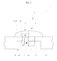
- FIG. 3 is a partially sectioned side view of another sliding surface element 1 according to the invention with sliding system 3 is shown.
- the sliding system 3 has a sliding element 5, which has an opening 52, and at least one base element 4 which can be arranged on the carrier 10 and which is arranged in the opening 52 of the sliding element 5.
- the sliding element 5 is arranged in this embodiment via a punching element 6 spaced from the carrier 10.
- This spacer element 6 made of, for example, a vibration-absorbing soft material leads to a better load capacity of the sliding surface element 1 and also to a noise reduction in the intended use of Gleit vomelements 1 for artificial ski facilities.
- the sliding element 5 has a convex (?) Sliding surface 2, which, viewed in cross-section, is approximately semicircular.
- a base member 4 On the opposite side of the sliding surface 2 of the sliding member 5, an opening 52 is arranged, in which a base member 4 is fixed.
- the base element 4 has a base 40 and three fixing elements 43 protruding from the base 40.
- a web 42 is arranged at the base 40 of the base member.
- the fixing elements 43 of the base element 4 have a coating 7 on their side facing the carrier 10.
- the base 40 of the base element 4 also has a coating 7 on its side opposite the sliding element 5.
- This coating 7 is materially connected to the fixing elements and the base 40 of the base member 4, about 0.8 mm thick and consists of a polymeric material.
- the base 40 and the fixing elements 43 of the base element 4 are made of a polymeric material such as ABS, while the coating 7 is also made of a polymeric material selected from the group of thermoplastic elastomers and in this embodiment of a thermoplastic polyurethane.
- the coating 7 is produced in a per se known injection molding together with the fixing element 43 and the base 40 in one operation and thus leads to optimal production conditions for the base member 4th
- the base element 4 is cohesively arranged via the web 42 of the base 40 in an undercut 53 of the opening 52 of the sliding element 5.
- the coating 7 arranged on the base 40 and the fixing elements 43 of the base element 4 it is thus possible, when the sliding surface element 1 is used properly for artificial ski installations, to compensate for certain vibrations and to lead to a noise reduction.
- Another advantage is that even production-related tolerances, in particular the first opening 11 of the carrier 10 but also of the sliding member 5 are advantageously compensated by the flexible coating 7.
- the sliding system 3 has in this embodiment, a sliding member 5, which is made of the material porcelain.
- the base member 4 is made in this embodiment of the polymeric material.
- the sliding system 3 comprising the sliding member 5 and the base member 4 is made in this embodiment, that the sliding member 5 is introduced in a first operation in a per se known injection mold and in a second operation, the base member 4 consisting of the base 40 and the arranged thereon fixing elements 43 molded, which in a third operation to the base 40 and the fixing elements 43 arranged thereon, the flexible coating 7 is molded.
Landscapes
- Engineering & Computer Science (AREA)
- Architecture (AREA)
- Civil Engineering (AREA)
- Structural Engineering (AREA)
- Compositions Of Macromolecular Compounds (AREA)
- Fittings On The Vehicle Exterior For Carrying Loads, And Devices For Holding Or Mounting Articles (AREA)
- Sliding-Contact Bearings (AREA)
Abstract
Description
- Die Erfindung betrifft ein Gleitflächenelement für künstliche Skianlagen, insbesondere Skisprunganlagen, Langlaufloipen oder Gleithänge, umfassend wenigstens einen Träger, sowie wenigsten einem eine Gleitfläche bildenden Gleitsystem gemäß dem Oberbegriff des Anspruches 1.
- Ein derartiges Gleitflächenelement ist beispielsweise in der
DE 202 111 37 U1 offenbart. Dieses weist ein Grundflächenelement aus einem Polymermaterial auf, in dem Keramikkörper in einem Gitterraster voneinander beabstandet fixiert sind, die mit ihrer Stirnfläche über das Grundflächenelement definiert überstehen.
Beim bestimmungsgemäßen Gebrauch des Gleitflächenelementes kommt es durch die Reibung zwischen dem Ski und den Keramikkörpern zu einer Abnutzung sowohl an der Oberfläche der Keramikkörper als auch an der Gleitfläche des Skis, wobei beide abhängig von der jeweiligen Werkstoffart unterschiedlich abgenutzt werden.
Nachteilig bei diesem Gleitflächenelement wird gesehen, dass bei einer Abnutzung einzelner Gleitelemente bzw. Keramikkörper diese nicht separat ersetzt werden können, sondern es muss das gesamte Gleitflächenelement ersetzt werden.
Ein weiterer Nachteil wird darin gesehen, dass für die Veränderung der Anzahl und / oder der Anordnung der einzelnen Gleitelemente bzw. Keramikkörper jeweils unterschiedliche Gleitflächenelemente hergestellt werden müssen, was sowohl in der Herstellung als auch in der Lagerhaltung sehr kostenintensiv ist.
Ebenfalls nachteilig wird gesehen, dass die Gleiteigenschaften des Gleitflächenelementes bedingt durch die Gleitelemente bzw. Keramikkörper immer gleich sind, das heißt, diese können nicht den unterschiedlichen Jahreszeiten bzw. Witterungen oder unterschiedlichen Materialien der Ski angepasst werden. - Die vorliegende Erfindung hat sich somit die Aufgabe gestellt, ein Gleitflächenelement aufzuzeigen, welches wirtschaftlich und kostengünstig herstellbar ist, welches einfach montierbar bzw. demontierbar ist, dessen Verwendung den Verschleiß des Ski als auch des Gleitflächenelementes reduziert und das den geforderten Nutzungsbedingungen für Skianlagen schnell und einfach anpassbar ist.
- Die Aufgabe wird erfindungsgemäß gelöst durch ein Gleitflächenelement gemäß den Merkmalen des Anspruches 1. Weitere vorteilhafte Ausgestaltungen sind in den Unteransprüchen beschrieben.
- Es hat sich überraschend herausgestellt, dass ein Gleitflächenelement für künstliche Skianlagen, insbesondere Skisprunganlagen, Langlaufloipen oder Gleithänge, umfassend wenigstens einen Träger sowie wenigstens einem eine Gleitfläche bildenden Gleitsystem sich dadurch auszeichnet, dass das Gleitsystem wenigstens ein, wenigstens eine Öffnung aufweisendes, Gleitelement umfasst, sowie wenigstens ein am Träger anordenbares Basiselement, welches in der Öffnung des Gleitelements angeordnet ist. Durch dieses Gleitflächenelement ist es vorteilhafterweise möglich, jeweils einzelne verschlissene Gleitsysteme durch eine punktuelle Demontage zu entfernen und durch neue unverbrauchte Gleitsysteme zu ersetzen. Weiterhin ist es durch das erfindungsgemäße Gleitflächensystem möglich, neben einer geometrisch beliebigen Anordnung der Gleitsysteme auf den Träger auch weitere Gleitsysteme anzubringen, die unterschiedliche Eigenschaften aufweisen, so dass beispielsweise bei Skisprunganlagen die im Bereich des Absprungtisches montierten Gleitsysteme sich von denen in der daran angeordneten Anlaufspur unterscheiden.
- Das erfindungsgemäße Gleitflächenelement ist vorteilhafterweise so ausgebildet, dass das Basiselement stoffschlüssig und / oder formschlüssig und / oder kraftschlüssig in der Öffnung des Gleitelements angeordnet ist. Hierdurch ist es möglich, die Gleitsysteme wirtschaftlich und kostengünstig herzustellen bzw. zu konfektionieren.
- Ein weiterer Vorteil des erfindungsgemäßen Gleitflächenelementes besteht darin, dass die Gleitfläche des Gleitflächenelements durch das Gleitelement selbst gebildet ist. Hierdurch kann vorteilhafterweise der Verschleiß des Gleitsystems durch die Wahl der Werkstoffe des Gleitelements optimiert bzw. reduziert werden, während das im Gleitelement angeordnete Basiselement keinen oder nur unwesentlichen Verschleiß unterliegt.
- Ebenfalls vorteilhaft bei dem erfindungsgemäßen Gleitflächenelement wird gesehen, dass die das Basiselement aufnehmende Öffnung auf der der Gleitfläche gegenüberliegenden Seite des Gleitelements angeordnet ist. Dies lässt eine kostengünstige Herstellung und eine einfache Montage zu.
- Dabei hat es sich weiterhin als vorteilhaft herausgestellt, dass bei dem erfindungsgemäßen Gleitflächenelement die das Basiselement aufnehmende Öffnung des Gleitelementes wenigstens eine Hinterschneidung aufweist. Durch diese Ausgestaltung ist es möglich, das Basiselement aus verschiedenen Werkstoffen herzustellen und formschlüssig am Gleitelement zu fixieren.
- Bei dem erfindungsgemäßen Gleitflächenelement ist es weiterhin sehr vorteilhaft, dass das Gleitelement über wenigsten ein Distanzelement beabstandet zum Träger angeordnet ist. Diese führen vorteilhafterweise dazu, dass ein gewisser Toleranz- bzw. Schwingungsabgleich zwischen dem Träger und dem Gleitsystem möglich ist.
- In einer weiteren vorteilhaften Ausgestaltung des erfindungsgemäßen Gleitflächenelementes weist das Basiselement eine Basis und wenigstens ein von dieser Basis wegragendes Fixierelement auf durch welches das Gleitsystem sehr einfach in den Träger einbringbar und an diesem fixierbar ist. Ein weiterer Vorteil besteht darin, dass somit das Gleitelement bei Defekten bzw. erhöhtem Verschleiß auch wieder leicht demontierbar ist.
- Es hat sich weiterhin als vorteilhaft beim erfindungsgemäßen Gleitflächenelement herausgestellt, dass das Basiselement an seiner Basis wenigstens einen Steg aufweist. Dieser Steg dient vorteilhafterweise dazu, dass die Basis des Basiselements in die Öffnung des Gleitelements einbringbar und an der dort angeordneten Hinterschneidung formschlüssig fixierbar ist.
- Beim erfindungsgemäßen Gleitflächenelement wurde weiterhin gefunden, dass wenigstens ein Fixierelement des Basiselements an seiner dem Träger gegenüberliegenden Seite eine Beschichtung aufweist. Diese Beschichtung kann beispielsweise aus einem weicheren Werkstoff hergestellt sein als das Fixierelement des Basiselements und führt vorteilhafterweise dazu, dass das Gleitsystem einfach in der Öffnung des Trägers anbringbar ist und das bei bestimmungsgemäßer Nutzung des Gleitflächenelements für künstliche Skianlagen Fertigungstoleranzen aber auch Belastungen durch die Nutzung ausgleichbar sind.
- Es hat sich ebenfalls als äußert vorteilhaft beim erfindungsgemäßen Gleitflächenelement herausgestellt, dass die Basis des Basiselements an wenigstens einer dem Gleitelement gegenüberliegenden Seite eine Beschichtung aufweist. Diese Beschichtung kann beispielsweise aus einem weicheren Werkstoff hergestellt sein als die Basis des Basiselements und führt zu einer stärken formschlüssigeren Verbindung des Basiselements im Gleitelement. Die Beschichtung ist dabei so ausgebildet, dass sie eine Dicke von etwa 0,1 mm bis etwa 7 mm, vorzugsweise von etwa 0,2 mm bis etwa 5 mm aufweist.
- Dabei hat es sich als vorteilhaft herausgestellt, dass die Beschichtung einstückig und / oder stoffschlüssig mit dem Fixierelement und / oder der Basis des Basiselements verbunden ist. Dies führt einerseits zu optimalen Herstellungskosten des erfindungsgemäßen Gleitflächenelements. Der Werkstoff der Beschichtung weist dabei eine Härte Shore A von 40 bis etwa 95 gemessen nach DIN 53505, vorzugsweise eine Härte Shore A von 50 bis 95 auf.
- Ein weiterer Vorteil des erfindungsgemäßen Gleitflächenelementes besteht darin, dass der Werkstoff der Beschichtung ausgewählt ist aus der Gruppe der Thermoplastischen Elastomere bspw. auf Olefinbasis und/oder auf Urethanbasis, der vernetzten thermoplastischen Elastomere auf Olefinbasis, der Thermoplastischen Copolyester, der Styrol-Blockcopolymere (SBS, SEBS, SEPS, SEEPS und MBS) sowie der Thermoplastischen Copolyamide, der weihmacherhaltigen Werkstoffe, bevorzugt Polypropylen, Acrylnitril-Butadien-Styrol-Copolymerisat, Polycarbonat, Polyvinylchlorid, Polymethylmethacrylat, Polyethylenterephthalat, Polyurethan und dgl., sowie aus Mischungen dieser Werkstoffe. Dies führt einerseits zu einer kostengünstigen Herstellung des im erfindungsgemäßen Gleitflächenelements angeordneten Basiselementes und führt andererseits dazu, dass das erfindungsgemäße Gleitflächenelement für verschiedenste Beanspruchungen und verschiedenste künstliche Skianlagen konstruierbar bzw. dimensionierbar ist.
- Das erfindungsgemäße Gleitflächenelement weist vorteilhafterweise ein Basiselement auf, das aus einem polymeren Werkstoff hergestellt ist. Unter polymerem Werkstoff sind Materialien gemeint, wie Polyvinylchlorid (PVC); Polyolefin, wie Polypropylen (PP) oder Polyethylen (PE); styrolbasiertes Polymer, wie Polystyrol (PS) oder Styrol-Butadien-Copolymer mit überwiegendem Styrolanteil (SB) oder Acrylnitril-Styrol-Acrylester-Copolymere (ASA) oder Acrylnitril-Butadien-Styrol-Copolymere (ABS) oder Styrolacrylnitril (SAN); Polybutylentherephthalat (PBT); Polyethylentherephthalat (PET); Polyoxymethylen (POM); Polyamid (PA); Polymethylmethacrylat (PMMA); Polyphenylenoxid (PPO); Polyetheretherketon (PEEK); Polyphenylensulfid (PPS); Liquid Crystal Polymer (LCP); Polyamidimide (PAI); Polyvinylidenfluorid (PVDF); Polyphenylsulfon (PPSU); Polyaryletherketon (PAEK); Polyacrylnitril (PAN); Polychlortrifluorethylen (PCTFE); Polyetherketon (PEK); Polyimid (PI); Polyisobuten (PIB); Polyphthalamid (PPA); Polypyrrol (PPY);Polytetrafluorethylen (PTFE); Polyurethan (PUR); Polyvinylalkohol (PVA); Polyvinylacetat (PVAC); Polyvinylidenchlorid (PVDC); sowie Mischungen aus wenigstens zwei dieser Materialien.
Diese polymeren Werkstoffe weisen durchaus noch an sich bekannte Füll- und / oder Verstärkungsstoffe auf, die die mechanischen Eigenschaften positiv beeinflussen insbesondere Glasfaser, Glaskugeln aber auch Füllstoffe wie Kreide, Teflon und dergleichen. Die Wahl der Werkstoffe lässt eine kostengünstige Herstellung zu und ebenfalls eine unterschiedliche Dimensionierung des erfindungsgemäßen Gleitflächenelementes. - Ein weiterer Vorteil des erfindungsgemäßen Gleitflächenelementes besteht darin, dass das Gleitelement aus einem keramischen und / oder silikatischen Werkstoff und / oder Porzellan hergestellt ist. Dies führt vorteilhafterweise dazu, dass bei bestimmungsgemäßen Einsatz des Gleitflächenelements für künstliche Skianlagen optimale Bedingungen für die Nutzer diese Skianlagen über alle Jahreszeiten realisierbar sind.
- Die eingesetzten keramischen Werkstoffe sind ausgewählt aus den Tonkeramiken, Porzellan, technischen Keramiken, Verbundkeramiken, der Oxid- bzw. Nichtoxidkeramiken und dergleichen. Unter silikatischen Werkstoffen sind insbesondere Glas bzw. Glaskeramiken zu nennen, aber auch Emaille. Als Porzellan können Hartporzellan mit einer Zusammensetzung von etwa 50 % Kaolin, 25 % Quarz sowie 25 % Feldspat oder Weichporzellan mit einer Zusammensetzung von etwa 25 % Kaolin, 45 % Quarz sowie 30 % Feldspat zum Einsatz kommen.
- Ebenfalls vorteilhaft bei dem erfindungsgemäßen Gleitflächenelement ist, dass das Gleitelement als Noppe, Quader, Zylinder, Pyramide, Walze, Halbkugel, Kugel und dergleichen ausgebildet ist. Hierdurch ist die Herstellung des Gleitelements selbst kostengünstig und variabel realisierbar, während das erfindungsgemäße Gleitflächenelement verschiedensten Anforderungen der künstlichen Skianlagen aber auch gesetzlicher Bestimmungen problemlos genügen kann.
- Das erfindungsgemäße Gleitflächenelement ist weiterhin so aufgebaut, dass das Gleitsystem über wenigstens ein Fixierelement des Basiselements form- und / oder kraftschlüssig an einer ersten Öffnung des Trägers angeordnet ist. Dies lässt eine kostengünstige und wirtschaftliche Herstellung des erfindungsgemäßen Gleitflächenelements zu, wobei auch die Demontage einzelner Gleitsysteme aus dem Träger einfach und wirtschaftlich möglich ist.
- Dabei hat es sich weiterhin als vorteilhaft herausgestellt, dass der Träger im Bereich der ersten Öffnung eine geringere Wandstärke aufweist als im restlichen Bereich, was einerseits die Materialkosten reduziert und andererseits für eine exakte Fixierung des Gleitsystems im Träger erforderlich ist.
- Weiterhin vor Vorteil bei dem erfindungsgemäßen Gleitflächenelement ist, dass gegenüber der ersten Öffnung des Trägers eine zweite Öffnung angeordnet ist. Diese führt ebenfalls zu reduzierten Material- und damit Herstellungskosten. Die zweite Öffnung kann dabei vorteilhafterweise axial gegenüberliegend der ersten Öffnung angeordnet sein, so dass die Montage des Gleitsystems beim erfindungsgemäßen Gleitflächenelement leicht realisierbar ist.
- Dabei ist das erfindungsgemäße Gleitflächenelement weiterhin so ausgebildet, dass die erste Öffnung und / oder die zweite Öffnung des Trägers im Querschnitt kreisförmig, prismatisch, sternförmig und dergleichen ausgebildet ist. Dies führt zu reduzierten Herstellungskosten einerseits und zu einer optimalen Fixierung der Gleitsysteme beim erfindungsgemäßen Gleitflächenelement andererseits.
- Ebenfalls vorteilhaft für das erfindungsgemäße Gleitflächenelement wurde festgestellt, dass das Gleitelement an seiner der Basis gegenüberliegende Oberfläche konkav und / oder konvex ausgebildet sein kann. Hierdurch sind insbesondere die Gleiteigenschaften des Gleitflächenelementes optimal und variabel ausbildbar. Das erfindungsgemäße Gleitflächenelement für künstliche Skianlagen kann somit nicht nur kostengünstig und wirtschaftlich hergestellt bzw. montiert werden, sondern es kann auch im bestimmungsgemäßen Gebrauch jederzeit durch Einsatz neuer Gleitsysteme bei Verschleiß ersetzt bzw. durch Einsatz neuer sowie unterschiedlicher Gleitsysteme ebenso den unterschiedlichen Anforderungen an einzelne Abschnitte der künstlichen Skianlagen und auch geforderten unterschiedlichen Nutzungsbedingungen angepasst werden.
- Durch die Wahl der Geometrie und / oder der Werkstoffe der im Gleitsystem angeordneten Gleitelemente und / oder Basiselement ist es somit möglich, durch beispielsweise hochschleißfest Gleitelemente aus Porzellan kombiniert mit der einfachen und sicheren Fixierung von Basiselementen aus polymeren Materialien das erfindungsgemäße Gleitflächenelement für sehr lange Standzeiten von künstlichen Skianlagen optimal auszulegen.
- Es ist jedoch auch möglich, einzelne Abschnitte der beispielsweise künstlichen Skianlagen mit unterschiedlichen Gleitsystemen auszustatten sowie Gleitflächenelemente zur Verfügung zu stellen, die ein komfortables Gleiten bei deren bestimmungsgemäßer Nutzung ermöglichen und die auch zu einer Geräuschreduzierung bei deren bestimmungsgemäßer Verwendung beitragen.
- Die Erfindung soll nun an diesen nicht einschränkenden Ausführungsbeispielen näher beschrieben werden.
- Es zeigen:
- Fig. 1
- perspektivische Darstellung eines erfindungsgemäßen Gleitflächenelements
- Fig. 2
- teilweise geschnittene Seitenansicht eines erfindungsgemäßen Gleitflächenelements mit Gleitsystem
- Fig. 3
- teilweise geschnittene Seitenansicht eines weiteren erfindungsgemäßen Gleitflächenelements mit Gleitsystem.
- In der
Fig. 1 ist eine perspektivische Darstellung eines erfindungsgemäßen Gleitflächenelementes 1 dargestellt.
Dieses Gleitflächenelement 1 für künstliche Skianlagen, insbesondere Skisprunganlagen, Langlaufloipen oder Gleithänge, umfasst einen Träger 10 sowie mit einer Gleitfläche 2 ausgebildete Gleitsysteme 3.
Der Träger 10 des Gleitflächenelementes 1 ist in diesem Ausführungsbeispiel aus einem polymeren Werkstoff herstellt und weist in seiner Oberfläche verschiedene voneinander beabstandet angeordnete Öffnungen 11 auf. Die unterschiedlich dimensionierten Öffnungen 11 des Trägers 10 dienen dazu, unterschiedlich dimensionierte bzw. aus unterschiedlichen Werkstoffen hergestellte Gleitsysteme 3 aufzunehmen.
Durch die Geometrie, aber auch durch die Anordnung der unterschiedlichen Öffnungen 11 im Träger 10 des Gleitflächenelementes 1 ist es somit möglich, ein Gleitflächenelement 1 zur Verfügung zu stellen, welches wirtschaftlich und kostengünstig herstellbar bzw. montierbar ist, dessen Verwendung den Verschleiß sowohl der Gleitsysteme 3 als auch der Ski reduziert und das den entsprechend geforderten Nutzungsbedingungen schnell und einfach anpassbar ist. - Der Träger 10 des Gleitflächenelementes 1 ist in diesem Ausführungsbeispiel in seiner Außenkontur etwa rechteckig ausgebildet. Es liegt jedoch auch im Rahmen der Erfindung, dass der Träger 10 des Gleitflächenelementes 1 prismatisch, quadratisch und dergleichen ausgebildet sein kann.
Es liegt weiterhin im Rahmen der Erfindung, dass der Träger 10 des Gleitflächenelementes 1 aus metallischem und/oder polymerem und/oder keramischem und/oder silikatischem Werkstoff hergestellt ist. - Die Öffnungen 11 des Trägers 10 können dabei im eigentlichen Herstellungsverfahren, beispielsweise im an sich bekannten Spritzgießverfahren, eingebracht werden, es liegt jedoch auch im Rahmen der Erfindung, dass die Öffnungen 11 des Trägers 10 erst nachträglich bzw. auch erst kurz vor der Montage auf den künstlichen Skianlagen einbringbar sind.
- In der
Fig. 2 ist eine teilweise geschnittene Seitenansicht eines Gleitflächenelements 1 mit einem Gleitsystem 3 dargestellt.
Das Gleitsystem 3 umfasst in diesem Ausführungsbeispiel ein Gleitelement 5 sowie ein an diesem angeordnetes Basiselement 4.
Das Gleitelement 5 ist in diesem Ausführungsbeispiel im Querschnitt kreisförmig ausgebildet und weist eine konkave Oberfläche auf, welche die Gleitfläche 2 bildet.
Das Gleitelement 5 weist an seiner der Gleitfläche 2 gegenüberliegenden Seite eine Öffnung 52 auf, in die eine Hinterschneidung 53 eingebracht ist. In der Öffnung 52 des Gleitelements 5 ist das Basiselement 4 angeordnet, welches in diesem Ausführungsbeispiel formschlüssig über den Steg 42 der Basis 40 in der Hinterschneidung 53 der Öffnung 52 des Gleitelements 5 fixiert ist.
Das Basiselement 4 ist in diesem Ausführungsbeispiel so ausgebildet, dass es eine Basis 40 sowie zwei von dieser Basis wegragende Fixierelemente 43 aufweist.
Die Basis 40 des Basiselements 4 ist in diesem Ausführungsbeispiel über an sich bekannte Klebstoffe stoffschlüssig in der Öffnung 52 des Gleitelements 5 fixiert.
Das Gleitsystem 3 ist am Träger 10 so angeordnet, dass das Gleitelement 5 auf der Oberfläche des Trägers 10 aufliegt und die von der Basis 40 des Basiselements 4 wegragenden Fixierelemente 43 an der reduzierten Wanddicke des Trägers 10 hinter der ersten Öffnung 11 kraftschlüssig angeordnet sind. - Der Träger 10 weist in diesem Ausführungsbeispiel axial gegenüber der ersten Öffnung 11 eine zweite Öffnung 12 auf, die im Querschnitt gesehen ebenfalls kreisförmig ausgebildet ist, aber mit einem größeren Durchmesser als die erste Öffnung 11.
Das Gleitsystem 3 ist somit optimal am Träger 10 des erfindungsgemäßen Gleitflächenelementes 1 montierbar aber auch demontierbar angeordnet.
Sollte bei bestimmungsgemäßer Nutzung des bestimmungsgemäßen Gleitflächenelements 1 die Gleitfläche 2 nicht mehr optimal sein bzw. das Gleitelement 5 verschlissen sein, kann dies durch einfache mechanische Mittel aus den Öffnungen 11, 12 des Trägers 10 entfernt und durch neue Gleitsysteme 3 ersetzt werden. - In der
Fig. 3 ist eine teilweise geschnittene Seitenansicht eines weiteren erfindungsgemäßen Gleitflächenelementes 1 mit Gleitsystem 3 dargestellt.
Das Gleitsystem 3 weist ein, eine Öffnung 52 aufweisendes Gleitelement 5 auf, sowie wenigstens ein am Träger 10 anordenbares Basiselement 4, welches in der Öffnung 52 des Gleitelements 5 angeordnet ist.
Das Gleitelement 5 ist in diesem Ausführungsbeispiel über ein Stanzelement 6 beabstandet zum Träger 10 angeordnet. Dieses Distanzelement 6 aus einem beispielsweise schwingungsaufnehmenden weichen Material führt zu einer besseren Belastbarkeit des Gleitflächenelementes 1 und auch zu einer Geräuschreduzierung bei der bestimmungsgemäßen Nutzung des Gleitflächenelements 1 für künstliche Skianlagen. - Das Gleitelement 5 weist in diesem Ausführungsbeispiel eine konvexe (?) Gleitfläche 2 auf, die im Querschnitt gesehen etwa halbkreisförmig ausgebildet ist.
An der der Gleitfläche 2 gegenüberliegenden Seite des Gleitelements 5 ist eine Öffnung 52 angeordnet, in der ein Basiselement 4 fixiert ist.
Das Basiselement 4 weist eine Basis 40 sowie drei von der Basis 40 wegragende Fixierelemente 43 auf. An der Basis 40 des Basiselements ist ein Steg 42 angeordnet.
Die Fixierelemente 43 des Basiselements 4 weisen an ihrer dem Träger 10 gegenüberliegenden Seite eine Beschichtung 7 auf.
Weiterhin weist die Basis 40 des Basiselements 4 an ihrer dem Gleitelement 5 gegenüberliegenden Seite ebenfalls eine Beschichtung 7 auf. - Diese Beschichtung 7 ist stoffschlüssig mit den Fixierelementen und der Basis 40 des Basiselements 4 verbunden, etwa 0,8 mm dick und besteht aus einem polymeren Werkstoff.
- Die Basis 40 und die Fixierelemente 43 des Basiselements 4 sind aus einem polymeren Werkstoff hergestellt wie beispielsweise ABS, während die Beschichtung 7 ebenfalls aus einem polymeren Werkstoff hergestellt ist, ausgewählt aus der Gruppe der thermoplastischen Elastomere und in diesem Ausführungsbeispiel aus einem thermoplastischen Polyurethan.
Die Beschichtung 7 wird im an sich bekannten Spritzgießverfahren zusammen mit dem Fixierelement 43 und der Basis 40 in einem Arbeitsgang hergestellt und führt somit zu optimalen Herstellungsbedingungen für das Basiselement 4. - Das Basiselement 4 ist über den Steg 42 der Basis 40 in einer Hinterschneidung 53 der Öffnung 52 des Gleitelements 5 stoffschlüssig angeordnet.
Durch die an der Basis 40 und den Fixierelementen 43 des Basiselements 4 angeordneten Beschichtung 7 ist es somit bei bestimmungsgemäßer Nutzung des Gleitflächenelementes 1 für künstliche Skianlagen möglich bestimmte Schwingungen auszugleichen und zu einer Geräuschreduzierung zu führen.
Ein weiterer Vorteil besteht darin, dass auch fertigungsbedingte Toleranzen insbesondere der ersten Öffnung 11 des Trägers 10 aber auch des Gleitelements 5 durch die flexible Beschichtung 7 vorteilhafterweise ausgleichbar sind.
Das Gleitsystem 3 weist in diesem Ausführungsbeispiel ein Gleitelement 5 auf, welches aus dem Werkstoff Porzellan hergestellt ist.
Das Basiselement 4 ist in diesem Ausführungsbeispiel aus dem polymerem Werkstoff hergestellt.
Das Gleitsystem 3 umfassend das Gleitelement 5 sowie das Basiselement 4 ist in diesem Ausführungsbeispiel so hergestellt, dass das Gleitelement 5 in einem ersten Arbeitsgang in ein an sich bekanntes Spritzgießwerkzeug eingebracht ist und das in einem zweiten Arbeitsgang das Basiselement 4 bestehend aus der Basis 40 sowie den daran angeordneten Fixierelementen 43 angespritzt, das in einem dritten Arbeitsgang an die Basis 40 sowie die daran angeordneten Fixierelemente 43 die flexible Beschichtung 7 angespritzt wird.
Claims (15)
- Gleitflächenelement (1) für künstliche Skianlagen, insbesondere Skisprunganlagen, Langlaufloipen oder Gleithänge, umfassend wenigstens einen Träger (10), sowie wenigstens einem eine Gleitfläche (2) bildenden Gleitsystem (3), dadurch gekennzeichnet, dass das Gleitsystem (3) wenigstens ein, wenigstens eine Öffnung (52) aufweisendes, Gleitelement (5) umfasst, sowie wenigstens ein am Träger (10) anordenbares Basiselement (4), welches in der Öffnung (52) des Gleitelements (5) angeordnet ist.
- Gleitflächenelement (1) nach Anspruch 1, dadurch gekennzeichnet, dass das Basiselement (4) stoffschlüssig und / oder formschlüssig und / oder kraftschlüssig in der Öffnung (52) des Gleitelements (5) angeordnet ist.
- Gleitflächenelement (1) nach zumindest einem der vorhergehenden Ansprüche, dadurch gekennzeichnet, dass die Öffnung (52) auf der der Gleitfläche (2) gegenüberliegenden Seite des Gleitelements (5) angeordnet ist.
- Gleitflächenelement (1) nach zumindest einem der vorhergehenden Ansprüche, dadurch gekennzeichnet, dass die Öffnung (52) des Gleitelements (5) wenigstens eine Hinterschneidung (53) aufweist.
- Gleitflächenelement (1) nach zumindest einem der vorhergehenden Ansprüche, dadurch gekennzeichnet, dass das Gleitelement (5) über wenigstens ein Distanzelement (6) beabstandet zum Träger (10) angeordnet ist.
- Gleitflächenelement (1) nach zumindest einem der vorhergehenden Ansprüche, dadurch gekennzeichnet, dass das Basiselement (4) eine Basis (40) und wenigstens ein von dieser Basis wegragendes Fixierelement (43) aufweist.
- Gleitflächenelement (1) nach zumindest einem der vorhergehenden Ansprüche, dadurch gekennzeichnet, dass das Basiselement (4) an seiner Basis (40) wenigstens einen Steg (42) aufweist.
- Gleitflächenelement (1) nach zumindest einem der vorhergehenden Ansprüche, dadurch gekennzeichnet, dass wenigstens ein Fixierelement (43) des Basiselements (4) an seiner dem Träger (10) gegenüberliegenden Seite eine Beschichtung (7) aufweist.
- Gleitflächenelement (1) nach zumindest einem der vorhergehenden Ansprüche, dadurch gekennzeichnet, dass die Basis (40) des Basiselements (4) an wenigstens einer dem Gleitelement (5) gegenüberliegenden Seite eine Beschichtung (7) aufweist.
- Gleitflächenelement (1) nach zumindest einem der vorhergehenden Ansprüche, dadurch gekennzeichnet, dass die Beschichtung (7) stoffschlüssig mit dem Fixierelement (43) und / oder der Basis (40) des Basiselements (4) verbunden ist.
- Gleitflächenelement (1) nach zumindest einem der vorhergehenden Ansprüche, dadurch gekennzeichnet, dass das Basiselement (4) aus einem polymeren Werkstoff hergestellt ist.
- Gleitflächenelement (1) nach zumindest einem der vorhergehenden Ansprüche, dadurch gekennzeichnet, dadurch gekennzeichnet, dass das Gleitelement (5) aus einem keramischen und / oder silikatischen Werkstoff und/oder Porzellan hergestellt ist.
- Gleitflächenelement (1) nach zumindest einem der vorhergehenden Ansprüche, dadurch gekennzeichnet, dass das Gleitsystem (3) über wenigstens ein Fixierelement (43) des Basiselements (4) form- und / oder kraftschlüssig an einer ersten Öffnung (11) des Trägers (10) angeordnet ist.
- Gleitflächenelement (1) nach zumindest einem der vorhergehenden Ansprüche, dadurch gekennzeichnet, dass der Träger (10) im Bereich der ersten Öffnung (11) eine geringere Wanddicke aufweist.
- Gleitflächenelement (1) nach zumindest einem der vorhergehenden Ansprüche, dadurch gekennzeichnet, dass gegenüber der ersten Öffnung (11) des Trägers (10) eine zweite Öffnung (12) angeordnet ist.
Applications Claiming Priority (1)
| Application Number | Priority Date | Filing Date | Title |
|---|---|---|---|
| DE202013101160.6U DE202013101160U1 (de) | 2013-03-18 | 2013-03-18 | Gleitflächenelement für künstliche Skianlagen |
Publications (3)
| Publication Number | Publication Date |
|---|---|
| EP2781655A2 true EP2781655A2 (de) | 2014-09-24 |
| EP2781655A3 EP2781655A3 (de) | 2015-08-19 |
| EP2781655B1 EP2781655B1 (de) | 2017-08-30 |
Family
ID=50230925
Family Applications (1)
| Application Number | Title | Priority Date | Filing Date |
|---|---|---|---|
| EP14157612.4A Not-in-force EP2781655B1 (de) | 2013-03-18 | 2014-03-04 | Gleitflächenelement für künstliche Skianlagen |
Country Status (2)
| Country | Link |
|---|---|
| EP (1) | EP2781655B1 (de) |
| DE (1) | DE202013101160U1 (de) |
Citations (1)
| Publication number | Priority date | Publication date | Assignee | Title |
|---|---|---|---|---|
| DE20211137U1 (de) | 2002-07-24 | 2003-03-27 | ETEC Gesellschaft für technische Keramik mbH, 53797 Lohmar | Gleitflächenelement für künstliche Schianlagen |
Family Cites Families (2)
| Publication number | Priority date | Publication date | Assignee | Title |
|---|---|---|---|---|
| DE202007008386U1 (de) * | 2007-06-12 | 2008-10-16 | Rehau Ag + Co | Gleitflächenelement für künstliche Skianlagen |
| DE102011052662C5 (de) * | 2011-08-12 | 2019-08-14 | Peter Riedel Patent UG (haftungsbeschränkt) | Gleitplatte und Gleitplatten-System für eine Skisprunganlage |
-
2013
- 2013-03-18 DE DE202013101160.6U patent/DE202013101160U1/de not_active Expired - Lifetime
-
2014
- 2014-03-04 EP EP14157612.4A patent/EP2781655B1/de not_active Not-in-force
Patent Citations (1)
| Publication number | Priority date | Publication date | Assignee | Title |
|---|---|---|---|---|
| DE20211137U1 (de) | 2002-07-24 | 2003-03-27 | ETEC Gesellschaft für technische Keramik mbH, 53797 Lohmar | Gleitflächenelement für künstliche Schianlagen |
Also Published As
| Publication number | Publication date |
|---|---|
| EP2781655B1 (de) | 2017-08-30 |
| EP2781655A3 (de) | 2015-08-19 |
| DE202013101160U1 (de) | 2014-06-23 |
Similar Documents
| Publication | Publication Date | Title |
|---|---|---|
| AT508701B1 (de) | Zahnradanordnung | |
| AT510575A4 (de) | Zahnrad | |
| DE202012012228U1 (de) | Rotor für eine Maschinenwelle einer Elektrischen Axialflussmaschine | |
| EP2561169A2 (de) | Abstandhalter | |
| EP3369609B1 (de) | Stromschienensystem | |
| EP2781655B1 (de) | Gleitflächenelement für künstliche Skianlagen | |
| EP2742183B1 (de) | Gleitplatte und gleitplatten-system für eine skisprunganlage | |
| DE3621870A1 (de) | Rohrverbindung | |
| DE202011051571U1 (de) | Gleitflächenelement für künstliche Skianlagen | |
| DE202015006861U1 (de) | Schutzprofilsystem | |
| DE102010005661A1 (de) | Reinigungsmolch zur Rohrreinigung | |
| DE102025137034A1 (de) | System, insbesondere zum Aufhängen einer Vorhanganordnung | |
| DE102017129086A1 (de) | Profilanordnung | |
| DE102012103040B4 (de) | Stützwendel mit Rastmittel und Verfahren zur Herstellung einer Stützwendel | |
| EP3867542B1 (de) | Verfahren zur herstellung eines lagerkäfigs für eine scheibenbremse, formteil hierfür und lagerkäfig | |
| DE202014105159U1 (de) | Profilanordnung für eine Elektrode zur elektrolytischen Abscheidung von Metallen | |
| EP3613627B1 (de) | Stromschienensystem | |
| EP2107658A1 (de) | Abdeckteil, insbesondere Abdeckrahmen, für eine elektrische Installationsvorrichtung | |
| DE202012100911U1 (de) | Bodenbelag | |
| DE102013012595A1 (de) | Filterelement mit 2K-Rahmen | |
| DE202022100636U1 (de) | Aufnahmeanordnung für eine mehrdimensionale Strukturanordnung | |
| DE19606565A1 (de) | Kammerfüllprofile für Schienen für Schienenfahrzeuge | |
| DE102015104027B4 (de) | Verfahren zur Herstellung eines Federelementes mit einem Dämpfungselement | |
| DE202022100633U1 (de) | Verbindungsstruktur | |
| DE202015106625U1 (de) | Kantenleisten für Möbelstücke |
Legal Events
| Date | Code | Title | Description |
|---|---|---|---|
| PUAI | Public reference made under article 153(3) epc to a published international application that has entered the european phase |
Free format text: ORIGINAL CODE: 0009012 |
|
| 17P | Request for examination filed |
Effective date: 20140304 |
|
| AK | Designated contracting states |
Kind code of ref document: A2 Designated state(s): AL AT BE BG CH CY CZ DE DK EE ES FI FR GB GR HR HU IE IS IT LI LT LU LV MC MK MT NL NO PL PT RO RS SE SI SK SM TR |
|
| AX | Request for extension of the european patent |
Extension state: BA ME |
|
| PUAL | Search report despatched |
Free format text: ORIGINAL CODE: 0009013 |
|
| AK | Designated contracting states |
Kind code of ref document: A3 Designated state(s): AL AT BE BG CH CY CZ DE DK EE ES FI FR GB GR HR HU IE IS IT LI LT LU LV MC MK MT NL NO PL PT RO RS SE SI SK SM TR |
|
| AX | Request for extension of the european patent |
Extension state: BA ME |
|
| RIC1 | Information provided on ipc code assigned before grant |
Ipc: E01C 13/12 20060101AFI20150716BHEP |
|
| R17P | Request for examination filed (corrected) |
Effective date: 20160218 |
|
| RBV | Designated contracting states (corrected) |
Designated state(s): AL AT BE BG CH CY CZ DE DK EE ES FI FR GB GR HR HU IE IS IT LI LT LU LV MC MK MT NL NO PL PT RO RS SE SI SK SM TR |
|
| GRAP | Despatch of communication of intention to grant a patent |
Free format text: ORIGINAL CODE: EPIDOSNIGR1 |
|
| INTG | Intention to grant announced |
Effective date: 20170421 |
|
| GRAS | Grant fee paid |
Free format text: ORIGINAL CODE: EPIDOSNIGR3 |
|
| GRAA | (expected) grant |
Free format text: ORIGINAL CODE: 0009210 |
|
| AK | Designated contracting states |
Kind code of ref document: B1 Designated state(s): AL AT BE BG CH CY CZ DE DK EE ES FI FR GB GR HR HU IE IS IT LI LT LU LV MC MK MT NL NO PL PT RO RS SE SI SK SM TR |
|
| REG | Reference to a national code |
Ref country code: GB Ref legal event code: FG4D Free format text: NOT ENGLISH |
|
| REG | Reference to a national code |
Ref country code: CH Ref legal event code: EP |
|
| REG | Reference to a national code |
Ref country code: AT Ref legal event code: REF Ref document number: 923685 Country of ref document: AT Kind code of ref document: T Effective date: 20170915 |
|
| REG | Reference to a national code |
Ref country code: IE Ref legal event code: FG4D Free format text: LANGUAGE OF EP DOCUMENT: GERMAN |
|
| REG | Reference to a national code |
Ref country code: DE Ref legal event code: R096 Ref document number: 502014005202 Country of ref document: DE |
|
| REG | Reference to a national code |
Ref country code: NL Ref legal event code: MP Effective date: 20170830 |
|
| REG | Reference to a national code |
Ref country code: LT Ref legal event code: MG4D |
|
| PG25 | Lapsed in a contracting state [announced via postgrant information from national office to epo] |
Ref country code: LT Free format text: LAPSE BECAUSE OF FAILURE TO SUBMIT A TRANSLATION OF THE DESCRIPTION OR TO PAY THE FEE WITHIN THE PRESCRIBED TIME-LIMIT Effective date: 20170830 Ref country code: NO Free format text: LAPSE BECAUSE OF FAILURE TO SUBMIT A TRANSLATION OF THE DESCRIPTION OR TO PAY THE FEE WITHIN THE PRESCRIBED TIME-LIMIT Effective date: 20171130 Ref country code: SE Free format text: LAPSE BECAUSE OF FAILURE TO SUBMIT A TRANSLATION OF THE DESCRIPTION OR TO PAY THE FEE WITHIN THE PRESCRIBED TIME-LIMIT Effective date: 20170830 Ref country code: FI Free format text: LAPSE BECAUSE OF FAILURE TO SUBMIT A TRANSLATION OF THE DESCRIPTION OR TO PAY THE FEE WITHIN THE PRESCRIBED TIME-LIMIT Effective date: 20170830 Ref country code: HR Free format text: LAPSE BECAUSE OF FAILURE TO SUBMIT A TRANSLATION OF THE DESCRIPTION OR TO PAY THE FEE WITHIN THE PRESCRIBED TIME-LIMIT Effective date: 20170830 |
|
| PG25 | Lapsed in a contracting state [announced via postgrant information from national office to epo] |
Ref country code: ES Free format text: LAPSE BECAUSE OF FAILURE TO SUBMIT A TRANSLATION OF THE DESCRIPTION OR TO PAY THE FEE WITHIN THE PRESCRIBED TIME-LIMIT Effective date: 20170830 Ref country code: RS Free format text: LAPSE BECAUSE OF FAILURE TO SUBMIT A TRANSLATION OF THE DESCRIPTION OR TO PAY THE FEE WITHIN THE PRESCRIBED TIME-LIMIT Effective date: 20170830 Ref country code: GR Free format text: LAPSE BECAUSE OF FAILURE TO SUBMIT A TRANSLATION OF THE DESCRIPTION OR TO PAY THE FEE WITHIN THE PRESCRIBED TIME-LIMIT Effective date: 20171201 Ref country code: IS Free format text: LAPSE BECAUSE OF FAILURE TO SUBMIT A TRANSLATION OF THE DESCRIPTION OR TO PAY THE FEE WITHIN THE PRESCRIBED TIME-LIMIT Effective date: 20171230 Ref country code: BG Free format text: LAPSE BECAUSE OF FAILURE TO SUBMIT A TRANSLATION OF THE DESCRIPTION OR TO PAY THE FEE WITHIN THE PRESCRIBED TIME-LIMIT Effective date: 20171130 Ref country code: LV Free format text: LAPSE BECAUSE OF FAILURE TO SUBMIT A TRANSLATION OF THE DESCRIPTION OR TO PAY THE FEE WITHIN THE PRESCRIBED TIME-LIMIT Effective date: 20170830 |
|
| PG25 | Lapsed in a contracting state [announced via postgrant information from national office to epo] |
Ref country code: NL Free format text: LAPSE BECAUSE OF FAILURE TO SUBMIT A TRANSLATION OF THE DESCRIPTION OR TO PAY THE FEE WITHIN THE PRESCRIBED TIME-LIMIT Effective date: 20170830 |
|
| PG25 | Lapsed in a contracting state [announced via postgrant information from national office to epo] |
Ref country code: PL Free format text: LAPSE BECAUSE OF FAILURE TO SUBMIT A TRANSLATION OF THE DESCRIPTION OR TO PAY THE FEE WITHIN THE PRESCRIBED TIME-LIMIT Effective date: 20170830 Ref country code: CZ Free format text: LAPSE BECAUSE OF FAILURE TO SUBMIT A TRANSLATION OF THE DESCRIPTION OR TO PAY THE FEE WITHIN THE PRESCRIBED TIME-LIMIT Effective date: 20170830 Ref country code: RO Free format text: LAPSE BECAUSE OF FAILURE TO SUBMIT A TRANSLATION OF THE DESCRIPTION OR TO PAY THE FEE WITHIN THE PRESCRIBED TIME-LIMIT Effective date: 20170830 Ref country code: DK Free format text: LAPSE BECAUSE OF FAILURE TO SUBMIT A TRANSLATION OF THE DESCRIPTION OR TO PAY THE FEE WITHIN THE PRESCRIBED TIME-LIMIT Effective date: 20170830 |
|
| PG25 | Lapsed in a contracting state [announced via postgrant information from national office to epo] |
Ref country code: SK Free format text: LAPSE BECAUSE OF FAILURE TO SUBMIT A TRANSLATION OF THE DESCRIPTION OR TO PAY THE FEE WITHIN THE PRESCRIBED TIME-LIMIT Effective date: 20170830 Ref country code: IT Free format text: LAPSE BECAUSE OF FAILURE TO SUBMIT A TRANSLATION OF THE DESCRIPTION OR TO PAY THE FEE WITHIN THE PRESCRIBED TIME-LIMIT Effective date: 20170830 Ref country code: EE Free format text: LAPSE BECAUSE OF FAILURE TO SUBMIT A TRANSLATION OF THE DESCRIPTION OR TO PAY THE FEE WITHIN THE PRESCRIBED TIME-LIMIT Effective date: 20170830 Ref country code: SM Free format text: LAPSE BECAUSE OF FAILURE TO SUBMIT A TRANSLATION OF THE DESCRIPTION OR TO PAY THE FEE WITHIN THE PRESCRIBED TIME-LIMIT Effective date: 20170830 |
|
| REG | Reference to a national code |
Ref country code: DE Ref legal event code: R097 Ref document number: 502014005202 Country of ref document: DE |
|
| PLBE | No opposition filed within time limit |
Free format text: ORIGINAL CODE: 0009261 |
|
| STAA | Information on the status of an ep patent application or granted ep patent |
Free format text: STATUS: NO OPPOSITION FILED WITHIN TIME LIMIT |
|
| PGFP | Annual fee paid to national office [announced via postgrant information from national office to epo] |
Ref country code: DE Payment date: 20180331 Year of fee payment: 5 |
|
| 26N | No opposition filed |
Effective date: 20180531 |
|
| PG25 | Lapsed in a contracting state [announced via postgrant information from national office to epo] |
Ref country code: SI Free format text: LAPSE BECAUSE OF FAILURE TO SUBMIT A TRANSLATION OF THE DESCRIPTION OR TO PAY THE FEE WITHIN THE PRESCRIBED TIME-LIMIT Effective date: 20170830 |
|
| PG25 | Lapsed in a contracting state [announced via postgrant information from national office to epo] |
Ref country code: MT Free format text: LAPSE BECAUSE OF FAILURE TO SUBMIT A TRANSLATION OF THE DESCRIPTION OR TO PAY THE FEE WITHIN THE PRESCRIBED TIME-LIMIT Effective date: 20170830 |
|
| REG | Reference to a national code |
Ref country code: CH Ref legal event code: PL |
|
| GBPC | Gb: european patent ceased through non-payment of renewal fee |
Effective date: 20180304 |
|
| PG25 | Lapsed in a contracting state [announced via postgrant information from national office to epo] |
Ref country code: MC Free format text: LAPSE BECAUSE OF FAILURE TO SUBMIT A TRANSLATION OF THE DESCRIPTION OR TO PAY THE FEE WITHIN THE PRESCRIBED TIME-LIMIT Effective date: 20170830 |
|
| REG | Reference to a national code |
Ref country code: BE Ref legal event code: MM Effective date: 20180331 |
|
| REG | Reference to a national code |
Ref country code: IE Ref legal event code: MM4A |
|
| PG25 | Lapsed in a contracting state [announced via postgrant information from national office to epo] |
Ref country code: LU Free format text: LAPSE BECAUSE OF NON-PAYMENT OF DUE FEES Effective date: 20180304 |
|
| PG25 | Lapsed in a contracting state [announced via postgrant information from national office to epo] |
Ref country code: IE Free format text: LAPSE BECAUSE OF NON-PAYMENT OF DUE FEES Effective date: 20180304 |
|
| PG25 | Lapsed in a contracting state [announced via postgrant information from national office to epo] |
Ref country code: LI Free format text: LAPSE BECAUSE OF NON-PAYMENT OF DUE FEES Effective date: 20180331 Ref country code: CH Free format text: LAPSE BECAUSE OF NON-PAYMENT OF DUE FEES Effective date: 20180331 Ref country code: BE Free format text: LAPSE BECAUSE OF NON-PAYMENT OF DUE FEES Effective date: 20180331 Ref country code: GB Free format text: LAPSE BECAUSE OF NON-PAYMENT OF DUE FEES Effective date: 20180304 |
|
| PG25 | Lapsed in a contracting state [announced via postgrant information from national office to epo] |
Ref country code: FR Free format text: LAPSE BECAUSE OF NON-PAYMENT OF DUE FEES Effective date: 20180331 |
|
| REG | Reference to a national code |
Ref country code: DE Ref legal event code: R119 Ref document number: 502014005202 Country of ref document: DE |
|
| PG25 | Lapsed in a contracting state [announced via postgrant information from national office to epo] |
Ref country code: DE Free format text: LAPSE BECAUSE OF NON-PAYMENT OF DUE FEES Effective date: 20191001 |
|
| PG25 | Lapsed in a contracting state [announced via postgrant information from national office to epo] |
Ref country code: TR Free format text: LAPSE BECAUSE OF FAILURE TO SUBMIT A TRANSLATION OF THE DESCRIPTION OR TO PAY THE FEE WITHIN THE PRESCRIBED TIME-LIMIT Effective date: 20170830 |
|
| PG25 | Lapsed in a contracting state [announced via postgrant information from national office to epo] |
Ref country code: HU Free format text: LAPSE BECAUSE OF FAILURE TO SUBMIT A TRANSLATION OF THE DESCRIPTION OR TO PAY THE FEE WITHIN THE PRESCRIBED TIME-LIMIT; INVALID AB INITIO Effective date: 20140304 Ref country code: PT Free format text: LAPSE BECAUSE OF FAILURE TO SUBMIT A TRANSLATION OF THE DESCRIPTION OR TO PAY THE FEE WITHIN THE PRESCRIBED TIME-LIMIT Effective date: 20170830 |
|
| PG25 | Lapsed in a contracting state [announced via postgrant information from national office to epo] |
Ref country code: CY Free format text: LAPSE BECAUSE OF FAILURE TO SUBMIT A TRANSLATION OF THE DESCRIPTION OR TO PAY THE FEE WITHIN THE PRESCRIBED TIME-LIMIT Effective date: 20170830 Ref country code: MK Free format text: LAPSE BECAUSE OF NON-PAYMENT OF DUE FEES Effective date: 20170830 |
|
| PG25 | Lapsed in a contracting state [announced via postgrant information from national office to epo] |
Ref country code: AL Free format text: LAPSE BECAUSE OF FAILURE TO SUBMIT A TRANSLATION OF THE DESCRIPTION OR TO PAY THE FEE WITHIN THE PRESCRIBED TIME-LIMIT Effective date: 20170830 |
|
| REG | Reference to a national code |
Ref country code: AT Ref legal event code: MM01 Ref document number: 923685 Country of ref document: AT Kind code of ref document: T Effective date: 20190304 |
|
| PG25 | Lapsed in a contracting state [announced via postgrant information from national office to epo] |
Ref country code: AT Free format text: LAPSE BECAUSE OF NON-PAYMENT OF DUE FEES Effective date: 20190304 |