EP2780970B1 - Anlage zur bearbeitung von batterieplatten und zu deren anordnung in bereitgestellte batteriegehäuse - Google Patents
Anlage zur bearbeitung von batterieplatten und zu deren anordnung in bereitgestellte batteriegehäuse Download PDFInfo
- Publication number
- EP2780970B1 EP2780970B1 EP12823127.1A EP12823127A EP2780970B1 EP 2780970 B1 EP2780970 B1 EP 2780970B1 EP 12823127 A EP12823127 A EP 12823127A EP 2780970 B1 EP2780970 B1 EP 2780970B1
- Authority
- EP
- European Patent Office
- Prior art keywords
- battery
- processing
- station
- clamping
- arrangement
- Prior art date
- Legal status (The legal status is an assumption and is not a legal conclusion. Google has not performed a legal analysis and makes no representation as to the accuracy of the status listed.)
- Active
Links
Images



Classifications
-
- H—ELECTRICITY
- H01—ELECTRIC ELEMENTS
- H01M—PROCESSES OR MEANS, e.g. BATTERIES, FOR THE DIRECT CONVERSION OF CHEMICAL ENERGY INTO ELECTRICAL ENERGY
- H01M10/00—Secondary cells; Manufacture thereof
- H01M10/06—Lead-acid accumulators
- H01M10/12—Construction or manufacture
- H01M10/14—Assembling a group of electrodes or separators
-
- H—ELECTRICITY
- H01—ELECTRIC ELEMENTS
- H01M—PROCESSES OR MEANS, e.g. BATTERIES, FOR THE DIRECT CONVERSION OF CHEMICAL ENERGY INTO ELECTRICAL ENERGY
- H01M10/00—Secondary cells; Manufacture thereof
- H01M10/04—Construction or manufacture in general
- H01M10/0404—Machines for assembling batteries
-
- H—ELECTRICITY
- H01—ELECTRIC ELEMENTS
- H01M—PROCESSES OR MEANS, e.g. BATTERIES, FOR THE DIRECT CONVERSION OF CHEMICAL ENERGY INTO ELECTRICAL ENERGY
- H01M10/00—Secondary cells; Manufacture thereof
- H01M10/06—Lead-acid accumulators
- H01M10/12—Construction or manufacture
- H01M10/16—Suspending or supporting electrodes or groups of electrodes in the case
-
- Y—GENERAL TAGGING OF NEW TECHNOLOGICAL DEVELOPMENTS; GENERAL TAGGING OF CROSS-SECTIONAL TECHNOLOGIES SPANNING OVER SEVERAL SECTIONS OF THE IPC; TECHNICAL SUBJECTS COVERED BY FORMER USPC CROSS-REFERENCE ART COLLECTIONS [XRACs] AND DIGESTS
- Y02—TECHNOLOGIES OR APPLICATIONS FOR MITIGATION OR ADAPTATION AGAINST CLIMATE CHANGE
- Y02E—REDUCTION OF GREENHOUSE GAS [GHG] EMISSIONS, RELATED TO ENERGY GENERATION, TRANSMISSION OR DISTRIBUTION
- Y02E60/00—Enabling technologies; Technologies with a potential or indirect contribution to GHG emissions mitigation
- Y02E60/10—Energy storage using batteries
-
- Y—GENERAL TAGGING OF NEW TECHNOLOGICAL DEVELOPMENTS; GENERAL TAGGING OF CROSS-SECTIONAL TECHNOLOGIES SPANNING OVER SEVERAL SECTIONS OF THE IPC; TECHNICAL SUBJECTS COVERED BY FORMER USPC CROSS-REFERENCE ART COLLECTIONS [XRACs] AND DIGESTS
- Y02—TECHNOLOGIES OR APPLICATIONS FOR MITIGATION OR ADAPTATION AGAINST CLIMATE CHANGE
- Y02P—CLIMATE CHANGE MITIGATION TECHNOLOGIES IN THE PRODUCTION OR PROCESSING OF GOODS
- Y02P70/00—Climate change mitigation technologies in the production process for final industrial or consumer products
- Y02P70/50—Manufacturing or production processes characterised by the final manufactured product
-
- Y—GENERAL TAGGING OF NEW TECHNOLOGICAL DEVELOPMENTS; GENERAL TAGGING OF CROSS-SECTIONAL TECHNOLOGIES SPANNING OVER SEVERAL SECTIONS OF THE IPC; TECHNICAL SUBJECTS COVERED BY FORMER USPC CROSS-REFERENCE ART COLLECTIONS [XRACs] AND DIGESTS
- Y10—TECHNICAL SUBJECTS COVERED BY FORMER USPC
- Y10T—TECHNICAL SUBJECTS COVERED BY FORMER US CLASSIFICATION
- Y10T29/00—Metal working
- Y10T29/53—Means to assemble or disassemble
- Y10T29/5313—Means to assemble electrical device
- Y10T29/53135—Storage cell or battery
Definitions
- the invention relates to a system for processing of battery plates and arrangement of these in the battery housing provided for this purpose.
- the system consists of transport devices and individual processing stations, wherein the battery plates to be processed are arranged as plate packs in clamping cassettes for processing.
- the invention finds application in the manufacture of motor vehicle and commercial vehicle batteries.
- the object of the invention is to find a technical solution with which the deficiencies of the prior art can be overcome.
- the inventive solution should be characterized by a small footprint. With the reduction of cycle times, the production times and production costs are to be reduced. Suitable control and monitoring systems should contribute to the optimized quality assurance of the production of the battery plates and the arrangement of these in the battery case.
- the stations For necessary maintenance work on the processing stations, the stations should be designed to be easy to maintain, so that even for this no significant downtime of the system or additional processing times must be taken.
- the object is achieved by the features of claim 1.
- the advantageous embodiments are described in the subclaims.
- the system for processing of battery plates and arrangement of this in battery cases from a transport device and individual processing stations the battery plates to be processed are arranged as plate packs in clamping cassettes for processing.
- the clamping cassettes equipped with the plate packs are arranged in a vertically oriented and in this position a circular rotary movement exporting transport device, so that the movement of the clamping cassettes takes place as in a Ferris wheel. This offers the advantage that there is a very small footprint for the transport device.
- As processing stations are an insert box with at least a six-fold gripper system for assigning the battery plate packs in the clamping cassette, and an alignment and clamping device for the battery plate packs in the provided by the transport clamping cassette, a Fluxstation with drying unit and tin bath, a gate for sprueing the lead bridges with a Lead bath and a Einboxstation for Einboxen the ready-equipped battery plate packages provided in the provided battery boxes with at least a six-fold gripper system.
- the insert box advantageously has at least one six-fold gripper system for inserting the finished-sized plate packs from a storage buffer into the clamping cassette 3, in order to allow efficient provision of the clamping cassette with the plate packs efficiently.
- the tin bath of the flux station is advantageously equipped with a measuring system for the permanent measurement of the tin bath level.
- This measuring system passes on the measured value information to the tin wire metering, so that the tin bath level is always kept at a constant level.
- the measurement can be carried out practically as turbulence measurement. This measure essentially supports the constant maintenance of a necessary tin bath level in order to avoid sources of error during processing continuously and effectively.
- the gate station is used to cast the lead bridges and therefore has a subdivided by a partition wall into two basins melting kettle, wherein in one boiler half the lead melt and the supply of Lead ingots for the melt takes place while the other half of the boiler serves as a calming basin, from which the lead melt is transferred by means of a pump into the dip tank for sprueing the lead bridges.
- the melted lead is pumped into the settling tank by means of a continuously running pump from the other tank.
- At least one overflow bead is arranged in the partition wall between the settling tank and the tank for the lead supply of the melting vessel, which additionally regulates the height level of the lead melt in the settling tank of the melting pot.
- the ready-equipped battery plate packages in the provided battery boxes at least one of the cleaning of the Einboxrahmen serving cleaning device is arranged.
- This has a brushing and / or spraying system, which drives by means of a multiple-axis system in the provided Einboxrahmen before loading with battery plate packages in there and performs the cleaning and removal of dirt particles and deposits. This prevents dirt particles from sticking to the plate packs when they are being injected, so that they can be filled in with little space.
- This measure also serves to achieve a high standard of quality in the assembly of ready-made battery plates in provided battery housing.
- At least one triple gripper system is arranged at the Einboxstation, which removes the ready-prepared plate packs from the clamping cassettes, three packages at the same time. Thereafter, the plate packs are boxed into the battery boxes. During the transfer, the battery box is turned so that the next 3 packages can be inserted into the battery box.
- several triple gripper systems are arranged.
- the vertically oriented and circling transport device has at least one separate rotary device which serves to rotate the cassettes during transport to the next processing station for the chuck cassettes.
- the correct positioning of the clamping cassette for the next processing cycle during transport to this station takes place in a time-saving manner, so that no additional time required for this is required.
- each processing station has, if necessary, a separate, the reciprocating to the transport device serving own transport device.
- the maintenance work can be carried out partly without cycle time loss by provided exchange modules with quick-change devices.
- FIG. 1 to 5c There is a system for processing battery plates and the arrangement of these battery plates in the provided battery housing from transport devices and individual processing stations, such as an insertion stations, the tin bath, the lead gate station.
- the battery plates to be processed are arranged for processing as defined plate packs in a plurality of clamping cassettes provided for this purpose.
- these clamping cassettes equipped with plate packs are arranged in a transport device 1 which executes a vertical rotary movement.
- the individual processing stations 2.1 - 2.n peripheral but outside the circle of motion of the transport device 1 are arranged. From there, the processing stations 2.1 - 2.n are each arranged to be moved to the position of the positioned by the transport device 1 clamping cassette 3 by means of separate transport devices 4.
- the first processing station, the insertion box 2.1 comprises at least a six-fold gripper system for assigning the plate packs from a storage buffer into the clamping cassette 3, an alignment device for aligning and bending the plate lugs and a clamping device for clamping the plate packs for insertion into the transporting device 1 provided clamping cassettes 3.
- the clamping cassette 3 equipped with plate packs succeeded in reaching the position of the second processing station, the flux station 2.2.
- the flux station 2.2 By means of a horizontal slide as a separate transport device 4 of the flux station 2.2 this comes with the arranged tin bath 2.2.1.1 and the integrated measuring system 2.2.1.1, which operates as an eddy current measuring method, for continuously measuring the Zinnbadspiegels and Zinndrahtdostechnik 2.2.1.2 to the clamping cassette. 3
- the measuring system 2.2.1.1 and the tin-wire metering 2.2.1.2 are coupled with one another in terms of information technology.
- Both the tin bath 2.2.1 and the additionally arranged drying device can be brought up vertically to the transport device 1 by means of the separate transport device 4.
- the tin bath 2.2.1 can be moved in the vertical direction on the clamping cassette 3. This is turned down before immersion with the driving and can so dip to the brought up from under Zinnbad 2.2.1.
- the clamping cassette is transported by the transport device to the processing station 3 as a result of the vertical rotational movement.
- the lead bridge sprue takes place.
- the casting station 2.3 has a lead bath 2.3.1 with a melting vessel 2.3.1.2.
- the melting pot 2.3.1.2 is in turn divided by a partition 2.3.1.4 into two sub-basins.
- the supply of lead ingots for the lead melt takes place.
- the soothing of the molten lead takes place.
- the lead is continuously pumped by means of a pump 2.3.1.3 from the one boiler half into the settling tank of the melting kettle 2.3.1.2.
- the partition 2.3.1.4 between the calming basin and the basin for the lead supply of the smelting boiler 2.3.1.1 at least one overflow bead 2.3.1.5 is arranged, which is the Level of lead melt in the settling tank of the smelting boiler additionally regulated by permanent overflow, since the lead surface of the two basins of the smelting boiler 2.3.1.2 have different height levels.
- the casting station 2.3 has an additional vertical transport device 4 for guiding the sprue mold 2.3.1.1 to the clamping cassette 3. Via an additional horizontal displacement device as a transport device 4, it is possible to exchange the entire sprue mold 2.3.1.1 for maintenance and / or repair work, so that the processing cycle of the transport device does not have to be interrupted.
- the clamping cassette 3 is transported by means of the transport device 1 by their vertical rotation to the position of the Einboxstation 2.4 for einboxing the fully equipped battery plate packages in the provided battery boxes.
- the Einboxstation 2.4 least one triple gripper system 2.4.1 and one of the cleaning of Einboxrahmen 5.1. Serving cleaning device 5 on. This serves to clean the expansion plates 2.4.4, the Einboxrahmen 2.4.3, which have impurities through their constant use.
- the cleaning station 5 has a brush 5.1. and / or spray system 5.2. which, by means of a multi-axis system into the provided Einboxrahmen before loading with battery plate packages into it and there carries out the cleaning and removal of dirt particles and deposits in 3D directions and performs safely.
- the advantages of the present invention are summarized in a technical solution for processing and arrangement of battery plates in provided battery housing, which is characterized by a small footprint, has a high level of monitoring functions and quality assurance measures for the machining processes in the individual processing stations, working efficiently and in succession the assignment of additional transport devices to the individual processing stations greatly reduces the time required for repair and maintenance tasks.
- the measures for the improvement of the quality assurance contribute to the fact that all processing steps for the production and assembly of the battery plate packages are permanently and safely controlled and regulated, so that the plant supplies a high degree of high-quality and fully equipped battery boxes.
Landscapes
- Engineering & Computer Science (AREA)
- Manufacturing & Machinery (AREA)
- Chemical & Material Sciences (AREA)
- Chemical Kinetics & Catalysis (AREA)
- Electrochemistry (AREA)
- General Chemical & Material Sciences (AREA)
- Primary Cells (AREA)
- Battery Electrode And Active Subsutance (AREA)
- Sealing Battery Cases Or Jackets (AREA)
- Secondary Cells (AREA)
- Casting Support Devices, Ladles, And Melt Control Thereby (AREA)
- Filling Of Jars Or Cans And Processes For Cleaning And Sealing Jars (AREA)
Description
- Die Erfindung betrifft eine Anlage zur Bearbeitung von Batterieplatten und Anordnung dieser in die dafür bereitgestellten Batteriegehäuse. Die Anlage besteht aus Transportvorrichtungen und einzelnen Bearbeitungsstationen, wobei die zu bearbeitenden Batterieplatten als Plattenpakete in Spannkassetten für die Bearbeitung angeordnet sind.
Die Erfindung findet Anwendung bei der Herstellung von Kraftfahrzeug- und Nutzfahrzeugbatterien. - Zur Fertigung von Kfz-Batterien ist es notwendig, eine Vielzahl von Elektrodenplatten in einzelne im Batteriegehäuse voneinander getrennt angeordnete Batteriezellen einzuordnen. Dabei sind die Elektrodenplatten zu einzelnen Pakten zusammengefasst und den Batteriezellen zugeordnet.
Eine Vorrichtung zum Verbinden von einzelnen Batterieplatten zu Paketen und zum Einsetzen dieser Pakete in Batteriekästen wird in derAT 008 261 U1 - Eine weitere Anlage zum Ausrüsten und Bestücken von Batteriekästen mit Plattenpaketen ist in der
DE 202009011262 U1 beschrieben. Diese Lösung zeigt auf, dass einzelne Bearbeitungsstationen um einen Hub-Drehtisch als Kompaktstation angeordnet sind und die Spannkassetten, welche mit den zu bearbeiteten Platten ausgestattet sind, werden von dem Hub-Drehtisch zu den einzelnen Transportstationen innerhalb der Kompaktstation zugeführt. Da die Bearbeitungsstationen in dieser Kompaktstation fest integriert angeordnet sind, ist der Zugriff auf diese Stationen während der Fertigung nicht möglich. Dadurch sind separate Wartungsarbeiten erforderlich, falls es zu einem Wartungsbedarf kommt. Außerdem wird die Spannkassette in der Bearbeitungsstation gedreht, was einen separaten zusätzlichen Takt erfordert. Dadurch verlängert sich die Zeit für die Bearbeitung der Platten und die Bestückung der Batteriegehäuse. Auf Grund der Anordnung der Kompaktstation mit Hub-Drehtisch und Bearbeitungsstationen in einer horizontalen Ebene ist der Platzbedarf für die Aufstellung einer solchen Anlage sehr groß. - Aufgabe der Erfindung ist es, eine technische Lösung zu finden, mit der die Mängel des Standes der Technik überwunden werden können.
Die erfinderische Lösung soll sich durch einen geringen Platzbedarf auszeichnen. Mit der Verringerung der Taktzeiten sollen die Herstellungszeiten und Fertigungskosten gesenkt werden. Geeignete Kontroll- und Überwachungssysteme sollen zur optimierten Qualitätssicherung der Fertigung der Batterieplatten und der Anordnung dieser in die Batteriegehäuse beitragen. - Für notwendige Wartungsarbeiten an den Bearbeitungsstationen sollen die Stationen wartungsfreundlich gestaltet sein, so dass auch hierfür keine wesentlichen Stillstandszeiten der Anlage oder zusätzlichen Bearbeitungszeiten in Anspruch genommen werden müssen.
- Erfindungsgemäß wird die Aufgabe durch die Merkmale des Anspruchs 1 gelöst. Die Vorteilhaften Ausgestaltungen sind in den Unteransprüchen beschrieben.
Danach besteht die Anlage zur Bearbeitung von Batterieplatten und Anordnung dieser in Batteriegehäusen aus einer Transportvorrichtung und einzelnen Bearbeitungsstationen, wobei die zu bearbeitenden Batterieplatten als Plattenpakete in Spannkassetten für die Bearbeitung angeordnet sind. Die mit den Plattenpaketen ausgestatteten Spannkassetten sind in einer vertikal ausgerichteten und in dieser Position eine kreisförmige Drehbewegung ausführende Transportvorrichtung angeordnet, so dass die Bewegung der Spannkassetten wie bei einem Riesenrad erfolgt.
Dies bietet den Vorteil, dass für die Transportvorrichtung ein sehr geringer Platzbedarf besteht. Des weiteren bietet es den Vorteil, dass die einzelnen Bearbeitungsstationen aus allen räumlichen Ebenen, als oben, unten und seitlich außerhalb der vertikal ausgerichteten Transportvorrichtung angeordnet sind, wobei diese von dort an die positionierte Spannkassette zugeführt und weggeführt werden können.
Dadurch dass die Bearbeitungsstationen aus dem Bearbeitungsbereich weggeführt werden können, wird gleichzeitig eine effiziente Lösung für die Wartung der Bearbeitungsstationen geschaffen. Diese kann bedienfreundlich und zeitsparend gewartet werden. - Als Bearbeitungsstationen sind eine Einlegebox mit mindestens einem Sechsfach-Greifersystem zur Zuordnung der Batterieplattenpakete in die Spannkassette, sowie eine Ausrichtvorrichtung und Spannvorrichtung für die Batterieplattenpakete in die von der Transportvorrichtung bereitgestellte Spannkassette, eine Fluxstation mit Trocknungseinheit und Zinnbad, eine Angussstation zum Angießen der Bleibrücken mit einem Bleibad und einer Einboxstation zum Einboxen der fertig ausgerüsteten Batterieplattenpakete in die bereitgestellten Batteriekästen mit wenigstens einem Sechsfach-Greifersystem vorgesehen.
- Die Einlegebox weist vorteilhafter Weise mindestens ein Sechsfach-Greifersystem zum Einlegen der fertig dimensionierten Plattenpakete aus einem Vorratspuffer in die Spannkassette 3 auf, um ein effektives Ausstatten der Spannkassetten mit den Plattenpaketen rationell zu ermöglichen.
- Das Zinnbad der Fluxstation ist dabei vorteilhafter Weise mit einem Messsystem zur dauerhaften Messung des Zinnbadspiegels ausgerüstet. Dieses Messsystem gibt die Messwertinformationen an die Zinndrahtdosierung weiter, so dass der Zinnbadspiegel immer auf einem konstanten Niveau gehalten wird. Die Messung kann dabei praktisch als Wirbeistrommessung durchgeführt werden. Diese Maßnahme unterstützt im Wesentlichen den konstanten Erhalt eines notwendigen Zinnbadspiegels, um Fehlerquellen während der Bearbeitung kontinuierlich und effektiv zu vermeiden.
- Die Angussstation dient dem Angiessen der Bleibrücken und verfügt deshalb über ein durch eine Trennwand in zwei Becken unterteilten Schmelzkessel, wobei in der einen Kesselhälfte die Bleischmelze und die Zuführung von Bleibarren für die Schmelze erfolgt wobei die andere Kesselhälfte als Beruhigungsbecken dient, von dem die Bleischmelze mittels Pumpe in das Tauchbecken zum Anguss der Bleibrücken überführt wird.
Um einen konstanten Niveauspiegel in dem Beruhigungsbecken des Schmelzkessels zu erhalten, wird mittels einer stetig laufenden Pumpe von dem anderen Becken das geschmolzene Blei in das Beruhigungsbecken gepumpt. Zusätzlich ist in der Trennwand zwischen dem Beruhigungsbecken und dem Becken für die Bleizuführung des Schmelzkessels wenigstens eine Überlaufsicke angeordnet, welche das Höhenniveau der Bleischmelze in dem Beruhigungsbecken des Schmelzkessels zusätzlich reguliert.
Auch diese Maßnahmen dienen stetig und effizient der dauerhaften Sicherung einer Angussqualität beim Bleibrückenanguss während des Fertigungsprozesses. - In der Einboxstation zum Einboxen der fertig ausgerüsteten Batterieplattenpakete in die bereitgestellten Batteriekästen ist wenigstens eine der Säuberung der Einboxrahmen dienende Reinigungsvorrichtung angeordnet. Diese verfügt über ein Bürsten- und/oder Sprühsystem, welches mittels eines Mehrfach-Achssystem in die bereitgestellten Einboxrahmen vor dem Bestücken mit Batterieplattenpaketen hinein fährt und dort die Reinigung und Entfernung von Schmutzpartikel und Anlagerungen durchführt.
Dadurch wird verhindert, dass beim Einboxen Schmutzpartikel an den Plattenpaketen anhaften können, das das Einboxen mit wenig Platzspielraum erfolgt.
Auch diese Maßnahme dient dem Erreichen eines hohen Qualitätsstandart bei der Bestückung von fertig aufbereiteten Batterieplatten in bereitgestellte Batteriegehäuse. - Um die Effektivität der Anlage zu erhöhen, ist an der Einboxstation wenigsten ein Dreifach-Greifersystem angeordnet, welches die fertig vorbereiteten Plattenpakete aus den Spannkassetten entnimmt, und zwar drei Pakete gleichzeitig. Danach werden die Plattenpakete in die Batteriekästen eingeboxt. Bei der Übergabe wird der Batteriekasten gedreht, so dass die nächsten 3 Pakete in den Batteriekasten eingefügt werden können. Vorteilhafter weiser sind mehrere Dreifach-Greifersysteme angeordnet.
- Die vertikal ausgerichtete und sich im Kreis drehende Transportvorrichtung verfügt über wenigstens eine separate Drehvorrichtung, welche dem Drehen der Spannkassetten während des Transports zur nächsten Bearbeitungsstation für die Spannkassetten dient. Zeitsparend erfolgt die richtige Positionierung der Spannkassette für den nächsten Bearbeitungsgang während des Transportes zu dieser Station, so dass hierfür kein notwendiger zusätzlicher Zeitaufwand erforderlich ist.
Um die einzelnen Bearbeitungsstationen an die Transportvorrichtung von Außen heran zu führen, verfügt jede Bearbeitungsstation bei Bedarf eine separate, dem Hin- und Herbewegen zur Transportvorrichtung dienende eigene Transportvorrichtung. - Die Vorteile dieser technischen Lösung zur Bearbeitung von Batterieplatten und Anordnung dieser in die dafür bereitgestellten Batteriegehäuse liegen vor allem in der Möglichkeit eines Platz sparenden Aufbaus dieser Anlage mit einem hohen Maß der Kontinuität der einzelnen Bearbeitungsstufenabläufe verbunden mit einer kontinuierlichen Überwachung zur Einhaltung von Qualitätskriterien und zur Vermeidung von Fehlerstellen innerhalb des Fertigungsprozesses.
- Durch das herausführen der einzelnen Bearbeitungsstufen aus dem Transportprozess können die Wartungsarbeiten zum Teil ohne Taktzeitverlust durch bereitgestellte Austauschmodule mit Schnellwechseleinrichtungen durchgeführt werden.
- Die Erfindung soll nachstehend an einem Ausführungsbeispiel näher erläutert werden.
In der beiliegenden Zeichnung zeigt - Fig. 1
- eine schematische Darstellung einer Anlage zur Bearbeitung vom Batterieplatten und Anordnung dieser in die dafür bereitgestellten Batteriegehäuse;
- Fig. 2
- eine schematische Darstellung der Fluxstation mit Zinnbad, Zinndrahtdosierung und Zinnspiegel-Messsystem;
- Fig. 3
- eine schematische Darstellung des Bleibades (2.3.1) mit den beiden (2.3.1.5)Becken des Schmelzkessels und Niveauausgleichs-Vorrichtungen;
- Fig. 4
- Seitenansicht einer Trennwand (2.3.1.4) mit Überlaufsicke;
- Fig. 5a
- eine schematische Seitenansicht der Reinigungsvorrichtung (5) für die Einboxrahmen (2.4.3) mit ihren Spreizbleche (2.4.4);
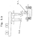
- Fig. 5b
- eine auszugsweise schematische Seitenansicht der Reinigungsvorrichtung (5);
- Fig. 5c
- eine schematische Draufsicht auf die Einboxstation 2.4 mit Reinigungssystem 5. für die Einboxrahmen (2.4.3) und Spreizbleche (2.4.4);
- Gemäß der
Figuren 1 bis 5c besteht eine Anlage zur Bearbeitung von Batterieplatten und zur Anordnung dieser Batterieplatten in dazu bereitgestellte Batteriegehäuse aus Transportvorrichtungen und einzelnen Bearbeitungsstationen, wie einer Einlegestationen, dem Zinnbad, der Bleiangussstation. Die zu bearbeitenden Batterieplatten werden dabei zur Bearbeitung als definierte Plattenpakete in mehreren dazu bereitgestellten Spannkassetten angeordnet Erfindungsgemäß sind diese mit Plattenpaketen ausgestatteten Spannkassetten in einer eine vertikale Drehbewegung ausführenden Transportvorrichtung 1 angeordnet. Zu dieser Transportvorrichtung 1 sind die einzelnen Bearbeitungsstationen 2.1 - 2.n peripher jedoch außerhalb des Bewegungskreises der Transportvorrichtung 1 angeordnet. Von dort sind die Bearbeitungsstationen 2.1 - 2.n jeweils an die Position der durch die Transportvorrichtung 1 positionierten Spannkassette 3 mittels separater Transporteinrichtungen 4 heranführbar angeordnet.
So umfasst die erste Bearbeitungsstation, die Einlegebox 2.1 mindestens ein Sechsfach-Greifersystem zum Zuordnen der Plattenpakete aus einem Vorratspuffer in die Spannkassette 3, einer Ausrichtvorrichtung zum Ausrichten und zum Anbiegen der Plattenfahnen und einer Spannvorrichtung zum Spannen der Plattenpakete für das Einbringen in die von der Transportvorrichtung 1 bereitgestellten Spannkassetten 3. - Durch vertikales Drehen der Transportvorrichtung 1 gelang die mit Plattenpaketen ausgestattete Spannkassette 3 zur Position der zweiten Bearbeitungsstation, der Fluxstation 2.2. Mittels eines horizontalen Schlitten als eine separate Transportvorrichtung 4 der Fluxstation 2.2 gelangt diese mit dem angeordneten Zinnbad 2.2.1 und dem integrierten Messsystem 2.2.1.1, welches als Wirbelstrommessverfahren arbeitet, zur kontinuierlichen Messung des Zinnbadspiegels und der Zinndrahtdosierung 2.2.1.2 an die Spannkassette 3. Zur optimalen Zinnbadspiegelregulieren sind das Messsystem 2.2.1.1 und die Zinndrahtdosierungen 2.2.1.2 informationstechnisch miteinander gekoppelt. Sowohl das Zinnbad 2.2.1 als auch die zusätzlich angeordnete Trocknungsvorrichtung sind dabei vertikal an die Transportvorrichtung 1 mittels der separaten Transportvorrichtung 4 heranfahrbar. Zusätzlich ist das Zinnbad 2.2.1 in vertikaler Richtung an der Spannkassette 3 heranführbar. Diese wird vor dem eintauchen mit den Fahren nach unten gedreht und kann so an das von unter herangeführte Zinnbad 2.2.1 eintauchen. Nach dem Trocknen wird die Spannkassette von der Transportvorrichtung zur Bearbeitungsstation 3 infolge der vertikalen Drehbewegung transportiert.
In der Angussstation 2.3 erfolgt der Bleibrückenanguss. Dazu weist die Gussstation 2.3 ein Bleibad 2.3.1 mit einem Schmelzkessel 2.3.1.2 auf.
Der Schmelzkessel 2.3.1.2 ist wiederum durch eine Trennwand 2.3.1.4 in zwei Teilbecken unterteilt. In der einen Kesselhälfte erfolgt die Zuführung von Bleibarren für die Bleischmelze. In der anderen Kesselhälfte erfolgt die Beruhigung des geschmolzenen Bleis. Das Blei wird mittels einer Pumpe 2.3.1.3 stetig von der einen Kesselhälfte in das Beruhigungsbecken des Schmelzkessels 2.3.1.2 gepumpt. In der Trennwand 2.3.1.4 zwischen dem Beruhigungsbecken und dem Becken für die Bleizuführung des Schmelzkessels 2.3.1.1 ist wenigstens eine Überlaufsicke 2.3.1.5 angeordnet, welche das Höhenniveau der Bleischmelze in dem Beruhigungsbecken des Schmelzkessels zusätzlich durch dauerhaften Überlauf reguliert, da die Bleispiegeloberflächen der beiden Becken des Schmelzkessels 2.3.1.2 über unterschiedliche Höhenniveaus verfügen.
Von dem Beruhigungsbecken des Schmelzkessels 2.3.1.2 gelangt das geschmolzene und eine sehr gute Qualität aufweisende Blei mittels einer weiteren Pumpe in eine Angussform 2.3.1.1 wo der Bleibrückenanguss erfolgt. Dazu weist die Gussstation 2.3 eine zusätzliche vertikale Transportvorrichtung 4 zum Heranführen der Angussform 2.3.1.1 an die Spannkassette 3 auf. Über eine zusätzliche horizontale Verschiebevorrichtung als Transportvorrichtung 4 besteht die Möglichkeit, die gesamte Angussform 2.3.1.1 für Wartungs- und/oder Reparaturarbeiten auszutauschen, so dass der Bearbeitungstaktverlauf der Transportvorrichtung nicht unterbrochen werden muss.
Nach dem Bleibrückenanguss wird die Spannkassette 3 mittels der Transportvorrichtung 1 durch ihr vertikales Drehen an die Position der Einboxstation 2.4 zum Einboxen der fertig ausgerüsteten Batterieplattenpakete in die bereitgestellten Batteriekästen transportiert.
Dazu weist die Einboxstation 2.4 wenigsten ein Dreifach-Greifersystem 2.4.1 und einer der Säuberung der Einboxrahmen 5.1. dienende Reinigungsvorrichtung 5 auf. Diese dient der Reinigung der Spreizbleche 2.4.4, der Einboxrahmen 2.4.3, welche durch ihren ständigen Einsatz Verunreinigungen aufweisen. Die Reinigungsstation 5 weist ein Bürsten- 5.1. und/oder Sprühsystem 5.2. auf, welches mittels eines Mehrfach-Achssystem in die bereitgestellten Einboxrahmen vor dem Bestücken mit Batterieplattenpaketen hinein fährt und dort die Reinigung und Entfernung von Schmutzpartikel und Anlagerungen in 3D- Richtungen vornimmt und sicher durchführt. - Die Vorteile der vorliegenden Erfindung bestehen zusammengefasst in einer technischen Lösung zur Bearbeitung und Anordnung von Batterieplatten in bereitgestellte Batteriegehäuse, welche sich durch einen geringen Platzbedarf auszeichnet, ein hohes Maß an Überwachungsfunktionen und Qualitätssicherungsmaßnahmen für die Bearbeitungsabläufe in den einzelnen Bearbeitungsstationen aufweist, effizient arbeitet und in Folge der Zuordnung von zusätzlichen Transportvorrichtungen zu den einzelnen Bearbeitungsstationen den Zeitaufwand für Reparatur- und Wartungsaufgaben immens reduziert. Vor allem die Maßnahmen zur Verbesserung der Qualitätssicherung tragen dazu bei, dass alle Bearbeitungsschritte zur Fertigung und Bestückung der Batterie-Plattenpakete dauerhaft und sicher kontrolliert und reguliert werden, so dass die Anlage ein hohes Maß an qualitativ hochwertigen und fertig bestückten Batteriekästen liefert.
-
- 1
- Transportvorrichtung für Spannkassetten
- 2.1 -2.n
- Bearbeitungsstationen
- 2.1
- Einlegebox
- 2.1.1
- Sechsfach-Greifersystem
- 2.2
- Fluxstation
- 2.2.1
- Zinnbad
- 2.2.1.1
- Messsystem für Zinnspiegelniveau
- 2.2.1.2
- Zinndrahtdosierung
- 2.3
- Gussstation
- 2.3.1.
- Bleibad
- 2.3.1.1
- Angussform
- 2.3.1.2
- Schmelzkessel
- 2.3.1.3
- Pumpe
- 2.3.1.4
- Trennwand
- 2.3.1.5
- Überlaufsicke
- 2.4
- Einboxstation
- 2.4.1
- Dreifach-Greifer
- 2.4.3
- Einboxrahmen
- 2.4.4
- Spreizbleche
- 3
- Spannkassetten
- 4
- separate Transportvorrichtungen der Bearbeitungsstationen
- 5
- Reinigungsvorrichtung
- 5.1
- Bürstensystem
- 5.2
- Sprühsystem
Claims (6)
- Anlage zur Bearbeitung von Batterieplatten und Anordnung dieser in Batteriegehäusen, bestehend aus Transportvorrichtungen und einzelnen Bearbeitungsstationen, wie Einlegestationen, Zinnbad, Bleiangußstation, wobei die zu bearbeitenden Batterieplatten als Plattenpakete in mehreren dazu bereitgestellten Spannkassetten für die Bearbeitung angeordnet sind, dadurch gekennzeichnet,
dass die mit den Plattenpaketen ausgestatteten Spannkassetten in einer vertikal ausgerichteten und sich in dieser Position im Kreis drehenden und eine vertikale Kreisbewegung der Spannkassetten vollziehende Transportvorrichtung (1) der Anlage angeordnet sind,
dass die einzelnen Bearbeitungsstationen (2.1 - 2.n) oben, unten und/oder seitlich außerhalb der sich in einer vertikal ausgerichteten Kreisbewegung drehenden Transportvorrichtung und von dort an die jeweils an der Position der Bearbeitungsstation (2.1 - 2.n) positionierte Spannkassette zuführbar angeordnet sind. - Anlage zur Bearbeitung von Batterieplatten und Anordnung dieser in Batteriegehäusen nach dem Anspruch 1, dadurch gekennzeichnet,
dass als Bearbeitungsstationen (2.1-2.n)- eine Einlegebox (2.1) mit mindestens einem Sechsfach-Greifersystem, einer Ausrichtvorrichtung und Spannvorrichtung für die Batterieplattenpakete in die von der Transportvorrichtung (1) bereitgestellte Spannkassette (3),- eine Fluxstation (2.2) mit Trocknungsvorrichtung und Zinnbad und das Zinnbad (2.2.1) der Fluxstation (2.2) ein der Zinnspiegelmessung dienendes Messsystem (2.2.1.1) und einem damit informationstechnisch gekoppelten Zinndrahtdosierung (2.2.1.2) ausgerüstet ist,- eine Gussstation (2.3) zum Angießen der Bleibrücken mit einem Bleibad (2.3.1) in dem zwischen Tauchbecken (2.3.1.1) und Schmelzkessel (2.3.1.2) eine dem dauerhaften Niveauausgleich der Bleischmelze dienende Pumpe (2.3.1.3.) angeordnet ist und in der Trennwand (2.3.1.4) zwischen Tauchbecken (2.3.1.1) und Schmelzkessel (2.3.1.2) wenigstens eine das Bleischmelzeniveau regulierende Überlaufsicke (2.3.1.5) angeordnet ist und- eine Einboxstation (2.4) zum Einboxen der fertig ausgerüsteten Batterieplattenpakete in die bereitgestellten Batteriekästen mit wenigstens einem Dreifach-Greifersystem und einer der Säuberung der Einboxrahmen (2.4.3) mit seinen Spreizplatten (2.4.4) dienenden Reinigungsvorrichtung (5), um die vertikal ausgerichtete Transportvorrichtung (1) und zu dieser mittels separat an den Bearbeitungsstationen (2.1 - 2n) angeordneten zusätzlichen Transportvorrichtungen (4) beweglich angeordnet sind. - Anlage zur Bearbeitung von Batterieplatten und Anordnung dieser in Batteriegehäusen nach einem der Ansprüche 1 und 2, dadurch gekennzeichnet, dass an der vertikal ausgerichteten und sich im Kreis drehenden Transportvorrichtung wenigstens eine dem Drehen der Spannkassetten während des Transports zur nächsten Bearbeitungsstation (2.1 - 2n) separate Drehvorrichtung für die Spannkassetten angeordnet ist.
- Anlage zur Bearbeitung von Batterieplatten und Anordnung dieser in Batteriegehäusen nach einem der Ansprüche 2 bis 3, dadurch gekennzeichnet, dass das im Zinnbad (2.2.1) angeordnete und der Zinnspiegelmessung dienende Messsystem (2.2.1.1) als Wirbelstrommesssystem ausgebildet ist.
- Anlage zur Bearbeitung von Batterieplatten und Anordnung dieser in Batteriegehäusen nach einem der Ansprüche 1 bis 4, dadurch gekennzeichnet, dass jede Bearbeitungsstation (2.1 - 2.n) bei Bedarf eine separate, dem Hin- und Herbewegen zur Transportvorrichtung dienende eigene Transportvorrichtung (4) aufweist.
- Anlage zur Bearbeitung von Batterieplatten und Anordnung dieser in Batteriegehäusen nach einem der Ansprüche 2 bis 5, dadurch gekennzeichnet, dass die Reinigungsvorrichtung (5) ein Bürsten- und/oder Sprühkopfsystem (5.1, 5.2) ausgebildet ist, wobei dieses System an über Bewegungsvorrichtung mit mehreren Dreh- und Bewegungsachsen angeordnet ist.
Priority Applications (1)
| Application Number | Priority Date | Filing Date | Title |
|---|---|---|---|
| SI201230617A SI2780970T1 (sl) | 2011-11-10 | 2012-11-08 | Sistem za obdelavo plošč baterije in za njihovo namestitev v obstoječe ohišje baterije |
Applications Claiming Priority (2)
| Application Number | Priority Date | Filing Date | Title |
|---|---|---|---|
| DE102011118092 | 2011-11-10 | ||
| PCT/DE2012/001072 WO2013067993A1 (de) | 2011-11-10 | 2012-11-08 | Anlage zur bearbeitung von batterieplatten und zu deren anordnung in bereitgestellte batteriegehäuse |
Publications (2)
| Publication Number | Publication Date |
|---|---|
| EP2780970A1 EP2780970A1 (de) | 2014-09-24 |
| EP2780970B1 true EP2780970B1 (de) | 2016-03-23 |
Family
ID=47683403
Family Applications (1)
| Application Number | Title | Priority Date | Filing Date |
|---|---|---|---|
| EP12823127.1A Active EP2780970B1 (de) | 2011-11-10 | 2012-11-08 | Anlage zur bearbeitung von batterieplatten und zu deren anordnung in bereitgestellte batteriegehäuse |
Country Status (14)
| Country | Link |
|---|---|
| US (2) | US20140304983A1 (de) |
| EP (1) | EP2780970B1 (de) |
| CN (1) | CN103999281B (de) |
| BR (1) | BR112014011004B1 (de) |
| CA (1) | CA2850865C (de) |
| DE (1) | DE102012021784A1 (de) |
| ES (1) | ES2578630T3 (de) |
| HU (1) | HUE029599T2 (de) |
| MX (1) | MX350625B (de) |
| PL (1) | PL2780970T3 (de) |
| PT (1) | PT2780970T (de) |
| RU (1) | RU2640356C2 (de) |
| SI (1) | SI2780970T1 (de) |
| WO (1) | WO2013067993A1 (de) |
Families Citing this family (8)
| Publication number | Priority date | Publication date | Assignee | Title |
|---|---|---|---|---|
| CA2893920A1 (en) | 2012-12-12 | 2014-06-19 | Sasit Industrietechnik Gmbh | Device and method for processing battery plates and arranging them in wet or agm battery cases for cars or trucks |
| PL3036789T3 (pl) * | 2013-08-19 | 2018-02-28 | Sasit Industrietechnik Gmbh | Instalacja do wytwarzania zarówno akumulatorów AGM, jak i akumulatorów z ciekłym elektrolitem do typów akumulatorów w samochodach osobowych i pojazdach użytkowych |
| KR101767847B1 (ko) * | 2016-12-14 | 2017-08-23 | 가부시키가이샤 지에스 유아사 | 납축전지의 극판군의 접속 방법, 납축전지의 제조 방법, 상기 제조 방법으로 제조된 납축전지, 및 납축전지의 극판군의 접속 장치 |
| KR101850657B1 (ko) * | 2017-10-26 | 2018-04-20 | 주식회사 신한정공 | 튜브식 양극판 제조장치 |
| DE102019000256A1 (de) * | 2018-01-17 | 2019-07-18 | Sasit Industrietechnik Gmbh | Gleitmittelsprühanlage sowie Gleitmittelauftragsverfahren für die Innenflächenbehandlung von Einführungs- und Montagehilfen in einer Packstation |
| EP3972742A1 (de) * | 2019-04-30 | 2022-03-30 | SMA Sächsische Maschinen- und Anlagenbau GmbH | Vorrichtung zum benetzen von aufnahme- und einführhilfen und/oder behälter- oder rahmenkonstruktionen für die verbesserte zuordnung von plattenpaketen innerhalb einer komplexen fertigungsanlage |
| CN112103551B (zh) * | 2020-10-26 | 2021-11-05 | 速博达(深圳)自动化有限公司 | 裸电芯夹紧翻转机构和锂离子电池生产线 |
| CN113193390B (zh) * | 2021-04-29 | 2022-07-05 | 深圳市普锐思高电子科技有限公司 | 一种铜片接线结构 |
Family Cites Families (22)
| Publication number | Priority date | Publication date | Assignee | Title |
|---|---|---|---|---|
| AT8261B (de) | 1901-08-20 | 1902-07-10 | Jacob Rapoport | Verfahren zur Herstellung geflammter Emailgegenstände. |
| GB1005313A (de) * | 1960-12-30 | |||
| DE2022163B2 (de) * | 1970-05-06 | 1972-12-14 | Varta Ag, 6000 Frankfurt | Automatisch arbeitende maschine zur herstellung von elektrischen akkumulatoren |
| US3926247A (en) * | 1974-10-29 | 1975-12-16 | Cominco Ltd | Lead sheet casting machine |
| US4502213A (en) * | 1979-07-09 | 1985-03-05 | General Electric Company | Apparatus for the automatic closure of electrochemical cells |
| DE3016984C2 (de) * | 1980-05-02 | 1984-03-29 | Goslarer Farbenwerke Dr. Hans Heubach GmbH & Co KG, 3394 Langelsheim | Verfahren und Vorrichtung zur einstufigen Herstellung von technischem Bleioxid |
| EP0095645B2 (de) * | 1982-05-20 | 1994-01-05 | Cosworth Research And Development Limited | Verfahren und Vorrichtung zum Schmelzen und Giessen von Metall |
| US5044067A (en) * | 1989-02-24 | 1991-09-03 | Caltec International, Inc. | Method for the manufacture of lead acid batteries and an associated apparatus and associated lead-acid battery |
| AT392371B (de) * | 1989-05-10 | 1991-03-25 | Elbak Batteriewerke Gmbh | Vorrichtung zum eintaschen und abstapeln von positiven oder negativen platten fuer akkumulatoren |
| DE10020284A1 (de) * | 2000-04-26 | 2001-10-31 | Stolberger Metallwerke Gmbh | Verfahren und Anordnung zum Regenerieren einer verunreinigten Metallschmelze |
| JP3862973B2 (ja) * | 2001-06-28 | 2006-12-27 | 古河電池株式会社 | 極板積層体の極板分離供給装置 |
| KR100420042B1 (ko) | 2001-09-06 | 2004-02-25 | 황충신 | 무전해액 밧데리의 튜브식 양극판 제조방법 및 그 장치 |
| UA50359C2 (en) * | 2001-12-27 | 2004-10-15 | Viktor Oleksandrov Dzenzerskyi | Method of unification of external parameters of acmethod of unification of external parameters of accumulator batteries when forming and charging the cumulator batteries when forming and charging the batteries in line production process batteries in line production process |
| AT8261U1 (de) | 2004-11-22 | 2006-04-15 | Goger Doris | Verfahren und anlage zum verbinden von batterieplatten zu paketen und zum einsetzen dieser pakete in batteriekästen |
| CN101061598B (zh) | 2004-11-22 | 2010-06-09 | Bm-电池机械有限公司 | 将各蓄电池板连接成板叠并将这些板叠插入蓄电池盒中的方法和装置 |
| CN2886822Y (zh) * | 2005-12-20 | 2007-04-04 | 上海伟事统自动化技术有限公司 | 一种用于包装极板的组群机构 |
| RU61061U1 (ru) * | 2006-07-03 | 2007-02-10 | Борис Иванович Трошкин | Участок нейтрализации электролита и утилизации шлама |
| RU2387054C2 (ru) * | 2007-12-19 | 2010-04-20 | Закрытое Акционерное Общество Производственное объединение "Комплекс" | Автоматизированный программно-аппаратный комплекс для заряда и тренировки аккумуляторных батарей "призма" |
| DE202009011262U1 (de) * | 2009-08-20 | 2009-12-24 | Sasit-Industrietechnik Gmbh Zwickau | Vorrichtung zur Bestückung und Ausrüstung von Kfz-Batteriegehäusen |
| CN201540926U (zh) * | 2009-10-26 | 2010-08-04 | 厦门文天数码机械有限公司 | 蓄电池极板配组包封机 |
| ES2799412T3 (es) * | 2009-11-06 | 2020-12-17 | Mitek Holdings Inc | Moldeado continuo de tira de aleación de plomo para electrodos de batería de alta resistencia |
| DE102010033436B4 (de) | 2010-08-04 | 2014-02-13 | Vb Autobatterie Gmbh & Co. Kgaa | Bestückungsstation zur Bestückung von Kraftfahrzeugbatteriegehäusen mit Elektrodenplattensätzen, Bestückungsanlage und Verfahren zum Bestücken von Kraftfahrzeugbatteriegehäusen mit Elektrodenplattensätzen |
-
2012
- 2012-11-08 SI SI201230617A patent/SI2780970T1/sl unknown
- 2012-11-08 PT PT128231271T patent/PT2780970T/pt unknown
- 2012-11-08 BR BR112014011004-2A patent/BR112014011004B1/pt not_active IP Right Cessation
- 2012-11-08 DE DE102012021784A patent/DE102012021784A1/de not_active Withdrawn
- 2012-11-08 WO PCT/DE2012/001072 patent/WO2013067993A1/de not_active Ceased
- 2012-11-08 CA CA2850865A patent/CA2850865C/en active Active
- 2012-11-08 ES ES12823127.1T patent/ES2578630T3/es active Active
- 2012-11-08 US US14/357,515 patent/US20140304983A1/en not_active Abandoned
- 2012-11-08 PL PL12823127.1T patent/PL2780970T3/pl unknown
- 2012-11-08 EP EP12823127.1A patent/EP2780970B1/de active Active
- 2012-11-08 RU RU2014114928A patent/RU2640356C2/ru active
- 2012-11-08 MX MX2014005552A patent/MX350625B/es active IP Right Grant
- 2012-11-08 HU HUE12823127A patent/HUE029599T2/en unknown
- 2012-11-08 CN CN201280050399.3A patent/CN103999281B/zh not_active Expired - Fee Related
-
2017
- 2017-05-18 US US15/599,217 patent/US11177511B2/en not_active Expired - Fee Related
Also Published As
| Publication number | Publication date |
|---|---|
| HUE029599T2 (en) | 2017-02-28 |
| DE102012021784A1 (de) | 2013-05-16 |
| CN103999281B (zh) | 2017-08-01 |
| MX350625B (es) | 2017-09-12 |
| PL2780970T3 (pl) | 2016-10-31 |
| SI2780970T1 (sl) | 2016-07-29 |
| CA2850865A1 (en) | 2013-05-16 |
| WO2013067993A1 (de) | 2013-05-16 |
| PT2780970T (pt) | 2016-07-08 |
| RU2014114928A (ru) | 2015-12-20 |
| CA2850865C (en) | 2020-07-21 |
| CN103999281A (zh) | 2014-08-20 |
| EP2780970A1 (de) | 2014-09-24 |
| BR112014011004B1 (pt) | 2020-09-29 |
| ES2578630T3 (es) | 2016-07-28 |
| US11177511B2 (en) | 2021-11-16 |
| US20140304983A1 (en) | 2014-10-16 |
| BR112014011004A2 (pt) | 2017-06-06 |
| RU2640356C2 (ru) | 2017-12-28 |
| MX2014005552A (es) | 2015-12-07 |
| US20170256824A1 (en) | 2017-09-07 |
Similar Documents
| Publication | Publication Date | Title |
|---|---|---|
| WO2013067993A1 (de) | Anlage zur bearbeitung von batterieplatten und zu deren anordnung in bereitgestellte batteriegehäuse | |
| DE4324575C2 (de) | Rechnergesteuerte Fertigungsanlage zur spanabhebenden Bearbeitung | |
| DE202009011262U1 (de) | Vorrichtung zur Bestückung und Ausrüstung von Kfz-Batteriegehäusen | |
| DE1814458A1 (de) | Automatisches Produktionssystem | |
| DE3409843A1 (de) | Verfahren und einrichtung zum herstellen von werkstuecken | |
| DE19934291A1 (de) | Verfahren und Vorrichtung zur mechanischen Bearbeitung von Werkstücken und zur Montage/Demontage von Baugruppen | |
| DE2623938B2 (de) | Vorrichtung zum Auswechseln der Elektroden für die elektrolytische Raffination von Metallen | |
| DE602004002165T2 (de) | Bearbeitungszentrum mit Werkzeugwechsler nach dem Pick-up Prinzip | |
| DE3213058A1 (de) | Verfahren und mechanismen zur positionierung eines werkzeuges relativ zu einem werkstueck | |
| CN106041605A (zh) | 一种具有定位切割功能的切割机 | |
| EP0921898B1 (de) | Werkzeugmaschinensystem | |
| EP3036789A1 (de) | Anlage zur herstellung von sowohl agm- als auch nassbatterien für pkw und nkw batterietypen | |
| DE102021114813A1 (de) | Verfahren und Vorrichtung zum Schweißen von Klingen | |
| EP0250830A2 (de) | Vorrichtung zum Verbinden von Polbrücken und Polen mit den Fahnenableitern eines Plattensatzes für eine Akkumulatorenzelle | |
| DE102020117455A1 (de) | Handhabungseinrichtung für eine Herstellungsumgebung | |
| EP3010670A1 (de) | VERFAHREN UND VORRICHTUNG ZUM ANGIEßEN VON VERBINDERN | |
| DE102018104199A1 (de) | Werkzeugmaschine mit Arbeitsraum, Rüstplatz und Roboterarm und Verfahren zu deren Betrieb | |
| AT8261U1 (de) | Verfahren und anlage zum verbinden von batterieplatten zu paketen und zum einsetzen dieser pakete in batteriekästen | |
| DE19753845C1 (de) | Handhabungssystem zum Zuführen von Werkstücken oder Werkstückträgern zu einer Bearbeitungseinrichtung | |
| EP1328667B1 (de) | Kompakte bearbeitungsanlage für druckzylinder | |
| DE202007018833U1 (de) | Werkzeugmaschine | |
| CN207533908U (zh) | 一种三轴可编程自动旋铆机 | |
| DE4414844A1 (de) | Zwei Werkzeugmaschinen mit gemeinsamem Werkzeugwechsler umfassende Bearbeitungszelle | |
| DE112014004674B4 (de) | Verfahren und Anordnungsverfahren zur Herstellung von gegossenen Anoden zur Verwendung bei der Elektroraffination von Metallen | |
| DE102004018120A1 (de) | Flexible Fertigungsanlage |
Legal Events
| Date | Code | Title | Description |
|---|---|---|---|
| PUAI | Public reference made under article 153(3) epc to a published international application that has entered the european phase |
Free format text: ORIGINAL CODE: 0009012 |
|
| 17P | Request for examination filed |
Effective date: 20140520 |
|
| AK | Designated contracting states |
Kind code of ref document: A1 Designated state(s): AL AT BE BG CH CY CZ DE DK EE ES FI FR GB GR HR HU IE IS IT LI LT LU LV MC MK MT NL NO PL PT RO RS SE SI SK SM TR |
|
| DAX | Request for extension of the european patent (deleted) | ||
| GRAP | Despatch of communication of intention to grant a patent |
Free format text: ORIGINAL CODE: EPIDOSNIGR1 |
|
| INTG | Intention to grant announced |
Effective date: 20150807 |
|
| GRAS | Grant fee paid |
Free format text: ORIGINAL CODE: EPIDOSNIGR3 |
|
| GRAA | (expected) grant |
Free format text: ORIGINAL CODE: 0009210 |
|
| AK | Designated contracting states |
Kind code of ref document: B1 Designated state(s): AL AT BE BG CH CY CZ DE DK EE ES FI FR GB GR HR HU IE IS IT LI LT LU LV MC MK MT NL NO PL PT RO RS SE SI SK SM TR |
|
| REG | Reference to a national code |
Ref country code: GB Ref legal event code: FG4D Free format text: NOT ENGLISH |
|
| REG | Reference to a national code |
Ref country code: CH Ref legal event code: EP |
|
| REG | Reference to a national code |
Ref country code: AT Ref legal event code: REF Ref document number: 783950 Country of ref document: AT Kind code of ref document: T Effective date: 20160415 |
|
| REG | Reference to a national code |
Ref country code: IE Ref legal event code: FG4D Free format text: LANGUAGE OF EP DOCUMENT: GERMAN |
|
| REG | Reference to a national code |
Ref country code: DE Ref legal event code: R096 Ref document number: 502012006472 Country of ref document: DE |
|
| REG | Reference to a national code |
Ref country code: RO Ref legal event code: EPE |
|
| REG | Reference to a national code |
Ref country code: PT Ref legal event code: SC4A Ref document number: 2780970 Country of ref document: PT Date of ref document: 20160708 Kind code of ref document: T Free format text: AVAILABILITY OF NATIONAL TRANSLATION Effective date: 20160622 |
|
| REG | Reference to a national code |
Ref country code: LT Ref legal event code: MG4D |
|
| REG | Reference to a national code |
Ref country code: NL Ref legal event code: MP Effective date: 20160323 |
|
| REG | Reference to a national code |
Ref country code: ES Ref legal event code: FG2A Ref document number: 2578630 Country of ref document: ES Kind code of ref document: T3 Effective date: 20160728 |
|
| PG25 | Lapsed in a contracting state [announced via postgrant information from national office to epo] |
Ref country code: FI Free format text: LAPSE BECAUSE OF FAILURE TO SUBMIT A TRANSLATION OF THE DESCRIPTION OR TO PAY THE FEE WITHIN THE PRESCRIBED TIME-LIMIT Effective date: 20160323 Ref country code: GR Free format text: LAPSE BECAUSE OF FAILURE TO SUBMIT A TRANSLATION OF THE DESCRIPTION OR TO PAY THE FEE WITHIN THE PRESCRIBED TIME-LIMIT Effective date: 20160624 Ref country code: HR Free format text: LAPSE BECAUSE OF FAILURE TO SUBMIT A TRANSLATION OF THE DESCRIPTION OR TO PAY THE FEE WITHIN THE PRESCRIBED TIME-LIMIT Effective date: 20160323 Ref country code: NO Free format text: LAPSE BECAUSE OF FAILURE TO SUBMIT A TRANSLATION OF THE DESCRIPTION OR TO PAY THE FEE WITHIN THE PRESCRIBED TIME-LIMIT Effective date: 20160623 |
|
| PG25 | Lapsed in a contracting state [announced via postgrant information from national office to epo] |
Ref country code: LV Free format text: LAPSE BECAUSE OF FAILURE TO SUBMIT A TRANSLATION OF THE DESCRIPTION OR TO PAY THE FEE WITHIN THE PRESCRIBED TIME-LIMIT Effective date: 20160323 Ref country code: LT Free format text: LAPSE BECAUSE OF FAILURE TO SUBMIT A TRANSLATION OF THE DESCRIPTION OR TO PAY THE FEE WITHIN THE PRESCRIBED TIME-LIMIT Effective date: 20160323 Ref country code: NL Free format text: LAPSE BECAUSE OF FAILURE TO SUBMIT A TRANSLATION OF THE DESCRIPTION OR TO PAY THE FEE WITHIN THE PRESCRIBED TIME-LIMIT Effective date: 20160323 Ref country code: RS Free format text: LAPSE BECAUSE OF FAILURE TO SUBMIT A TRANSLATION OF THE DESCRIPTION OR TO PAY THE FEE WITHIN THE PRESCRIBED TIME-LIMIT Effective date: 20160323 Ref country code: SE Free format text: LAPSE BECAUSE OF FAILURE TO SUBMIT A TRANSLATION OF THE DESCRIPTION OR TO PAY THE FEE WITHIN THE PRESCRIBED TIME-LIMIT Effective date: 20160323 |
|
| PG25 | Lapsed in a contracting state [announced via postgrant information from national office to epo] |
Ref country code: IS Free format text: LAPSE BECAUSE OF FAILURE TO SUBMIT A TRANSLATION OF THE DESCRIPTION OR TO PAY THE FEE WITHIN THE PRESCRIBED TIME-LIMIT Effective date: 20160723 Ref country code: EE Free format text: LAPSE BECAUSE OF FAILURE TO SUBMIT A TRANSLATION OF THE DESCRIPTION OR TO PAY THE FEE WITHIN THE PRESCRIBED TIME-LIMIT Effective date: 20160323 |
|
| REG | Reference to a national code |
Ref country code: FR Ref legal event code: PLFP Year of fee payment: 5 |
|
| PG25 | Lapsed in a contracting state [announced via postgrant information from national office to epo] |
Ref country code: SM Free format text: LAPSE BECAUSE OF FAILURE TO SUBMIT A TRANSLATION OF THE DESCRIPTION OR TO PAY THE FEE WITHIN THE PRESCRIBED TIME-LIMIT Effective date: 20160323 |
|
| REG | Reference to a national code |
Ref country code: SK Ref legal event code: T3 Ref document number: E 21562 Country of ref document: SK |
|
| REG | Reference to a national code |
Ref country code: DE Ref legal event code: R097 Ref document number: 502012006472 Country of ref document: DE |
|
| PLBE | No opposition filed within time limit |
Free format text: ORIGINAL CODE: 0009261 |
|
| STAA | Information on the status of an ep patent application or granted ep patent |
Free format text: STATUS: NO OPPOSITION FILED WITHIN TIME LIMIT |
|
| PG25 | Lapsed in a contracting state [announced via postgrant information from national office to epo] |
Ref country code: DK Free format text: LAPSE BECAUSE OF FAILURE TO SUBMIT A TRANSLATION OF THE DESCRIPTION OR TO PAY THE FEE WITHIN THE PRESCRIBED TIME-LIMIT Effective date: 20160323 |
|
| PG25 | Lapsed in a contracting state [announced via postgrant information from national office to epo] |
Ref country code: BG Free format text: LAPSE BECAUSE OF FAILURE TO SUBMIT A TRANSLATION OF THE DESCRIPTION OR TO PAY THE FEE WITHIN THE PRESCRIBED TIME-LIMIT Effective date: 20160623 |
|
| REG | Reference to a national code |
Ref country code: HU Ref legal event code: AG4A Ref document number: E029599 Country of ref document: HU |
|
| 26N | No opposition filed |
Effective date: 20170102 |
|
| REG | Reference to a national code |
Ref country code: IE Ref legal event code: MM4A |
|
| PG25 | Lapsed in a contracting state [announced via postgrant information from national office to epo] |
Ref country code: LU Free format text: LAPSE BECAUSE OF NON-PAYMENT OF DUE FEES Effective date: 20161130 |
|
| REG | Reference to a national code |
Ref country code: FR Ref legal event code: PLFP Year of fee payment: 6 |
|
| PG25 | Lapsed in a contracting state [announced via postgrant information from national office to epo] |
Ref country code: IE Free format text: LAPSE BECAUSE OF NON-PAYMENT OF DUE FEES Effective date: 20161108 |
|
| PG25 | Lapsed in a contracting state [announced via postgrant information from national office to epo] |
Ref country code: MC Free format text: LAPSE BECAUSE OF FAILURE TO SUBMIT A TRANSLATION OF THE DESCRIPTION OR TO PAY THE FEE WITHIN THE PRESCRIBED TIME-LIMIT Effective date: 20160323 Ref country code: MK Free format text: LAPSE BECAUSE OF FAILURE TO SUBMIT A TRANSLATION OF THE DESCRIPTION OR TO PAY THE FEE WITHIN THE PRESCRIBED TIME-LIMIT Effective date: 20160323 Ref country code: CY Free format text: LAPSE BECAUSE OF FAILURE TO SUBMIT A TRANSLATION OF THE DESCRIPTION OR TO PAY THE FEE WITHIN THE PRESCRIBED TIME-LIMIT Effective date: 20160323 |
|
| PG25 | Lapsed in a contracting state [announced via postgrant information from national office to epo] |
Ref country code: MT Free format text: LAPSE BECAUSE OF FAILURE TO SUBMIT A TRANSLATION OF THE DESCRIPTION OR TO PAY THE FEE WITHIN THE PRESCRIBED TIME-LIMIT Effective date: 20160323 |
|
| PG25 | Lapsed in a contracting state [announced via postgrant information from national office to epo] |
Ref country code: AL Free format text: LAPSE BECAUSE OF FAILURE TO SUBMIT A TRANSLATION OF THE DESCRIPTION OR TO PAY THE FEE WITHIN THE PRESCRIBED TIME-LIMIT Effective date: 20160323 Ref country code: TR Free format text: LAPSE BECAUSE OF FAILURE TO SUBMIT A TRANSLATION OF THE DESCRIPTION OR TO PAY THE FEE WITHIN THE PRESCRIBED TIME-LIMIT Effective date: 20160323 |
|
| P01 | Opt-out of the competence of the unified patent court (upc) registered |
Effective date: 20230505 |
|
| PGFP | Annual fee paid to national office [announced via postgrant information from national office to epo] |
Ref country code: SK Payment date: 20231102 Year of fee payment: 12 |
|
| PGFP | Annual fee paid to national office [announced via postgrant information from national office to epo] |
Ref country code: GB Payment date: 20231123 Year of fee payment: 12 |
|
| PGFP | Annual fee paid to national office [announced via postgrant information from national office to epo] |
Ref country code: SI Payment date: 20231102 Year of fee payment: 12 Ref country code: RO Payment date: 20231102 Year of fee payment: 12 Ref country code: PT Payment date: 20231102 Year of fee payment: 12 Ref country code: IT Payment date: 20231124 Year of fee payment: 12 Ref country code: HU Payment date: 20231122 Year of fee payment: 12 Ref country code: FR Payment date: 20231120 Year of fee payment: 12 Ref country code: DE Payment date: 20231121 Year of fee payment: 12 Ref country code: CZ Payment date: 20231102 Year of fee payment: 12 Ref country code: CH Payment date: 20231202 Year of fee payment: 12 Ref country code: AT Payment date: 20231121 Year of fee payment: 12 |
|
| PGFP | Annual fee paid to national office [announced via postgrant information from national office to epo] |
Ref country code: PL Payment date: 20231103 Year of fee payment: 12 Ref country code: BE Payment date: 20231120 Year of fee payment: 12 |
|
| PGFP | Annual fee paid to national office [announced via postgrant information from national office to epo] |
Ref country code: ES Payment date: 20240126 Year of fee payment: 12 |
|
| REG | Reference to a national code |
Ref country code: DE Ref legal event code: R119 Ref document number: 502012006472 Country of ref document: DE |
|
| REG | Reference to a national code |
Ref country code: SK Ref legal event code: MM4A Ref document number: E 21562 Country of ref document: SK Effective date: 20241108 |
|
| REG | Reference to a national code |
Ref country code: CH Ref legal event code: PL |
|
| REG | Reference to a national code |
Ref country code: AT Ref legal event code: MM01 Ref document number: 783950 Country of ref document: AT Kind code of ref document: T Effective date: 20241108 Ref country code: CH Ref legal event code: PL |
|
| PG25 | Lapsed in a contracting state [announced via postgrant information from national office to epo] |
Ref country code: PT Free format text: LAPSE BECAUSE OF NON-PAYMENT OF DUE FEES Effective date: 20250508 |
|
| GBPC | Gb: european patent ceased through non-payment of renewal fee |
Effective date: 20241108 |
|
| PG25 | Lapsed in a contracting state [announced via postgrant information from national office to epo] |
Ref country code: CH Free format text: LAPSE BECAUSE OF NON-PAYMENT OF DUE FEES Effective date: 20241130 |
|
| PG25 | Lapsed in a contracting state [announced via postgrant information from national office to epo] |
Ref country code: RO Free format text: LAPSE BECAUSE OF NON-PAYMENT OF DUE FEES Effective date: 20241108 Ref country code: AT Free format text: LAPSE BECAUSE OF NON-PAYMENT OF DUE FEES Effective date: 20241108 |
|
| PG25 | Lapsed in a contracting state [announced via postgrant information from national office to epo] |
Ref country code: SK Free format text: LAPSE BECAUSE OF NON-PAYMENT OF DUE FEES Effective date: 20241108 |
|
| PG25 | Lapsed in a contracting state [announced via postgrant information from national office to epo] |
Ref country code: CZ Free format text: LAPSE BECAUSE OF NON-PAYMENT OF DUE FEES Effective date: 20241108 |
|
| PG25 | Lapsed in a contracting state [announced via postgrant information from national office to epo] |
Ref country code: HU Free format text: LAPSE BECAUSE OF NON-PAYMENT OF DUE FEES Effective date: 20241109 |
|
| REG | Reference to a national code |
Ref country code: BE Ref legal event code: MM Effective date: 20241130 |
|
| REG | Reference to a national code |
Ref country code: SI Ref legal event code: KO00 Effective date: 20241109 |
|
| PG25 | Lapsed in a contracting state [announced via postgrant information from national office to epo] |
Ref country code: DE Free format text: LAPSE BECAUSE OF NON-PAYMENT OF DUE FEES Effective date: 20250603 |
|
| PG25 | Lapsed in a contracting state [announced via postgrant information from national office to epo] |
Ref country code: IT Free format text: LAPSE BECAUSE OF NON-PAYMENT OF DUE FEES Effective date: 20241108 |
|
| PG25 | Lapsed in a contracting state [announced via postgrant information from national office to epo] |
Ref country code: BE Free format text: LAPSE BECAUSE OF NON-PAYMENT OF DUE FEES Effective date: 20241130 Ref country code: GB Free format text: LAPSE BECAUSE OF NON-PAYMENT OF DUE FEES Effective date: 20241108 |
|
| PG25 | Lapsed in a contracting state [announced via postgrant information from national office to epo] |
Ref country code: FR Free format text: LAPSE BECAUSE OF NON-PAYMENT OF DUE FEES Effective date: 20241130 |
|
| REG | Reference to a national code |
Ref country code: ES Ref legal event code: FD2A Effective date: 20260102 |
|
| PG25 | Lapsed in a contracting state [announced via postgrant information from national office to epo] |
Ref country code: ES Free format text: LAPSE BECAUSE OF NON-PAYMENT OF DUE FEES Effective date: 20241109 |