EP2778424A2 - Pumpenaggregat - Google Patents
Pumpenaggregat Download PDFInfo
- Publication number
- EP2778424A2 EP2778424A2 EP14000461.5A EP14000461A EP2778424A2 EP 2778424 A2 EP2778424 A2 EP 2778424A2 EP 14000461 A EP14000461 A EP 14000461A EP 2778424 A2 EP2778424 A2 EP 2778424A2
- Authority
- EP
- European Patent Office
- Prior art keywords
- circular
- stator
- pump unit
- rotor
- unit according
- Prior art date
- Legal status (The legal status is an assumption and is not a legal conclusion. Google has not performed a legal analysis and makes no representation as to the accuracy of the status listed.)
- Granted
Links
Images

Classifications
-
- F—MECHANICAL ENGINEERING; LIGHTING; HEATING; WEAPONS; BLASTING
- F04—POSITIVE - DISPLACEMENT MACHINES FOR LIQUIDS; PUMPS FOR LIQUIDS OR ELASTIC FLUIDS
- F04D—NON-POSITIVE-DISPLACEMENT PUMPS
- F04D13/00—Pumping installations or systems
- F04D13/02—Units comprising pumps and their driving means
- F04D13/06—Units comprising pumps and their driving means the pump being electrically driven
- F04D13/0606—Canned motor pumps
- F04D13/0626—Details of the can
-
- F—MECHANICAL ENGINEERING; LIGHTING; HEATING; WEAPONS; BLASTING
- F04—POSITIVE - DISPLACEMENT MACHINES FOR LIQUIDS; PUMPS FOR LIQUIDS OR ELASTIC FLUIDS
- F04D—NON-POSITIVE-DISPLACEMENT PUMPS
- F04D29/00—Details, component parts, or accessories
- F04D29/60—Mounting; Assembling; Disassembling
- F04D29/62—Mounting; Assembling; Disassembling of radial or helico-centrifugal pumps
- F04D29/628—Mounting; Assembling; Disassembling of radial or helico-centrifugal pumps especially adapted for liquid pumps
Definitions
- the invention relates to a pump unit with a pump unit and an electric motor driving this, comprising a stator and a rotor rotating in a rotor space, wherein the stator is separated from the rotor space by a split tube.
- Such pump units are often used in applications as wet rotor, in which the rotor rotates in a liquid located in the rotor chamber. As a rule, this liquid is the pumped medium.
- Such types of pump units can be found for example in heating circulation pumps and coolant pumps, borehole, service water and sewage pumps. In wet runner pumps, the rotor is thus washed by medium.
- the stator is hermetically separated from this medium by a split tube.
- the bearings of the rotor are lubricated by the medium.
- Such constructions are maintenance-free and have a long service life.
- split tube is exposed to the high pressures in the pump chamber. For this reason, split tubes must have a high strength. It is known to produce metal cans. However, these have the disadvantage that, as a result of the stator field eddy currents are generated in the can, resulting in losses and the efficiency of the electric motor is significantly reduced.
- the object of the invention is to provide a pump unit with a split tube, which can be designed to achieve a high efficiency of the unit particularly thin-walled, but at the same time holds high internal pressures in the rotor or pump room.
- a pump unit is proposed with a pump unit and an electric motor driving this, which has a stator and a rotor rotating in a rotor space, the stator is separated from the rotor space by a split tube and between the gap tube and the stator is a Kreiskeititati, with the the split tube is supported on the stator.
- the strength of the can with respect to internal pressure is increased by supporting it against the stator, in particular the stator core.
- the stator in particular the stator core.
- very precise tolerances and dimensions must be observed without any further measures. For plastic components, this is not possible depending on the material or very difficult and expensive.
- the split tube may have a bottom at one axial end, so that the split tube forms a split pot.
- the can is inserted in the axial direction into the stator with play. Subsequently, the outer surfaces of the split tube are brought into contact over a large area by a relative rotation between the stator and the can with the inner surfaces of the stator. As a result, the can is clamped against the stator and there is a uniform light surface pressure along the peripheral surface of the compound.
- the clamping force i. the angle of rotation should not be particularly great. Incidentally, it must not be too large, because canned pipe forms a thin-walled hollow body which breaks when the clamping force is too high.
- the split tube has an outer peripheral surface, which has a circumferential circle diverging from the circular inner circular spline. Seen in radial cross-section, the outer circumference of the can thus forms a base circle on which the wedge profile rises.
- the split tube can thus be produced immediately together with the circular spline, in particular by injection molding as a plastic molded part.
- the stator can basically have any desired structure, in particular have loop windings or else concentrated windings.
- the stator has a central opening, also called bore, in which the rotor rotatably rests.
- an inner surface of the stator delimiting the opening has, in the circumferential direction, at least one outer circular spline profile which deviates from the circular shape and is complementary to the inner circular spline profile.
- the inner circumference of the stator consequently forms a base circle on which the complementary spline profile rises.
- the two circular splines thus complement each other form-fitting, so that the split tube can be applied flat to the stator.
- the stator has a plurality of pole shoes extending radially inwardly into the opening.
- pole shoes extending radially inwardly into the opening.
- a pole piece has an inner circumferential surface which partially delimits the central opening.
- the can is positively and non-positively connected only to these pole shoes which are formed with the complementary circular wedge profile.
- Said two pole shoes which have a circular wedge profile, are advantageously opposite one another, so that the split tube can be clamped between them.
- a plurality of pole pieces in particular, every second pole piece can wear the outer circular spline.
- all the pole shoes have an outer circular spline profile which deviates from the circular shape in the circumferential direction, so that the split tube fits all pole shoes, i. can support a large area.
- the circular wedge connection can be formed by a circular wedge, two or more circular wedges and correspondingly a circular wedge, two or more complementary circular wedges.
- the circular spline connection by three circular wedges on the outer peripheral surface of the split tube and three complementary Circular wedges on the inner peripheral surface of the stator form. This ensures that the circular wedge connection is self-centering and the split tube always rests concentrically in the stator.
- the outer circular spline can be formed by a single circular wedge or by multiple circular wedges.
- the complementary inner circular spline on the can has a single circular wedge or more circular wedges.
- the circular wedge or the circular wedges can be arranged along the inner circumference of the stator such that each pole piece has on its inner peripheral surface a partial section of the circular wedge or one of the circular wedges. This means that two, more or in the case of a single circular wedge all pole shoes together form the circular wedge or a circular wedge proportionally. Also, a pole piece may have two or more circular wedges.
- the outer circular spline is formed by a number of circular wedges, each pole piece has on its inner peripheral surface such a circular wedge.
- the number of circular wedges corresponds to the number of stator poles.
- the profile height of the inner circular spline can be comparatively small compared to the wall thickness of the can.
- the inner circular spline has a profile height of 1/20 to 1/5, preferably 1/10 of the wall thickness of the can.
- the slope of the circular wedges of the circular wedge connection between 1:20 to 1:50, so that the circular wedge connection can be solved for disassembly purposes again.
- the contour of the circular wedges is designed as a logarithmic spiral. This has the advantage that the connection partners of the circular wedge connection not linear but surface contact. The can is optimally supported by the stator.
- the circular wedge connection according to the invention offers the advantage that the split tube can also be fixed in the axial direction.
- the split tube may have on its outer circumference a radial projection which engages behind the stator, in particular a pole piece (7), in the inserted and stressed state of the split tube.
- this projection can be in the area between two pole shoes, for example. If the can is inserted axially, the projection is also twisted by its rotation and comes behind a pole piece to the plant. The split tube is thereby secured in the axial direction.
- the electric motor of the pump unit is provided with an electric motor having a wet-running rotor.
- the rotor space is flooded with a liquid and the rotor, i. in particular the rotor core, surrounded by a liquid and in accordance with liquid flows around in operation.
- the pump unit thus forms a wet-running pump, which can be used in particular as a heating circulation pump.
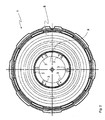
- FIG. 1 shows a stator 2 of an electric motor in the embodiment of a conventional EC motor in its front view.
- the electric motor drives Centrifugal pump unit. It comprises a laminated core consisting of a yoke ring 6 and six stator poles 7 attached thereto, which in turn each consist of a pole leg 7a and a pole piece 7b.
- the pole leg 7a is here attached by way of example via a dovetail connection 7c to the return ring 6.
- the pole legs 7 a each carry a winding 5, so that the electric motor has a total of six stator windings 5.
- Each winding 5 is wound on a winding support, which is supported by means of a rib-like structure on the back of the respective pole piece 7b.
- the pole pieces 7b each have a concave inner surface which, due to the axial extent of the pole pieces 7b, substantially corresponds to a cylindrical portion. Together, the pole pieces 7b define with their inner surface a central opening 11, in which the rotor, not shown, of the electric motor is arranged.
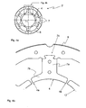
- FIG. 4a A representation of the stator 2 in cross section without windings 5 is in FIG. 4a shown, here the view opposite FIG. 1 from behind.
- FIG. 4b An enlargement of a section of this illustration, which comprises the upper stator pole 7 in cross-section, is shown in FIG. 4b displayed.
- FIG. 4b It can be seen that the profile of the inner surface of the pole pieces 7b of a circular section of a pure base circle 12, the in FIG. 4b is shown as a dotted line, differs in that it rises from one lateral end 4a in the circumferential direction to the other lateral end 4b and thus forms a circular wedge 4.
- each pole piece 7b ie each stator pole 7 is provided with a circular wedge 4.
- the circular wedges 4 rise in the cross-sectional profile of the pole pieces 7b radially inwardly into the opening 11 into it.
- FIG. 2 shows the rear view of a split pot, ie a closed end gap tube 1.
- the split tube 1 is thus closed at one axial end by a bottom 9.
- a molded-on flange 8 extends substantially radially outwardly. This covers the directed to the pump unit, not shown, end face of the stator 2.
- the outer peripheral surface of the can 1 has in cross section a deviating from the pure circular circular wedge profile with six circular wedges 3, which rise opposite the circular wedges 4 on the stator 2 in the opposite circumferential direction radially outward.
- the circular spline 4 on the stator and the circular spline 3 on the split tube 1 thus form complementary circular wedge profiles.
- the circular spline 4 Since the circular spline 4 is located radially on the stator 2 opposite the circular spline 3 on the gap tube 1, it is referred to as “outer circular spline" in the context of the invention. Accordingly, the circular spline 3 forms the gap tube 1, an "inner circular spline". However, these designations only relate to one another within their position within the pump unit and do not provide any information about the shape of the circular spline profiles.
- FIG. 2 is a view from the rear of the can 1, while FIG. 1 a representation of the stator 2 from the front shows.
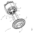
- the complementary property is clear when the back of the can 1 is inserted from the front into the opening 11 of the stator 2. This is in FIG. 3 shown.
- FIG. 3 shows an isometric exploded view of canned tube 1 and stator 2. They are part of a centrifugal pump assembly, in particular a heating circulation pump, which or a pump unit and an electric motor which drives the pump unit in a known manner.
- the stator 2 and the can 1 are part of the electric motor, which also includes a rotor rotating in a rotor chamber 10. The stator 2 is separated from this rotor chamber 10 through the can 1.
- the can 1 with clearance between the circular wedge contours 3, 4 is inserted axially into the opening 11 of the stator 2. Subsequently, the split tube 1 -in relation to FIG. 3 - Turned relative to the stator 2 counterclockwise, and / or the stator 2 in the clockwise direction relative to the can 1, so that the game disappears and the circular wedges 3 can 1 flat surface with the corresponding circular wedges 4 of the pole pieces 7 come to rest flat.
- a circular wedge connection 3, 4 by means of which the can 1 is supported on the stator 2 between the can 1 and the stator 2.
- the rotation must be done here only by a few degrees, since no forces in particular no torques between the can 1 and the stator 2 are transmitted. Essentially, in this case, only the large contact surface achievable by the circular wedge contour, with which the can 1 can be supported on the stator 2, in particular on the pole shoes 7b, so that the strength and stability of the can 1 against high internal pressures in the rotor chamber 10 is ensured. The internal pressure resistance of the can 1 is thereby significantly increased compared to a non-supported variant.
- Tolerance fluctuations are thereby safely compensated in a simple way, so that the requirements for the component tolerances can be reduced. Furthermore, with the same requirements, the wall thickness of the can 1 can be reduced, so that the magnetic gap between the stator 2 and rotor is reduced and the magnetic material can be reduced.
- the can 1 is made of plastic as an injection molded part in the embodiment shown. It has a wall thickness between 0.8 and 1.2mm.
- the circular spline 3 on the can 1 has a profile height of about 0.1 mm.
- the figures show only an exemplary variant of the invention.
- the circular wedges 4 may extend to the pole pieces 7 in the other circumferential direction. The same then applies correspondingly to the complementary circular wedges 3 on the can 1.
- fewer or more circular wedges 3, 4 are designed as pole shoes 7b, ie as stator poles 7 on the stator 2. It can For example, some stator poles 7 have no circular spline and accordingly not be involved in the support of the can 1. Alternatively, all stator poles 7 may have a circular wedge partial profile and in each case participate proportionally in the formation of a common circular wedge.
- a stator pole 7 is involved in the formation of more than one circular wedge or even forms two or more circular wedges.
- the split tube 1 has in the said variants then on its outer circumference circular wedges, which form a correspondingly complementary circular wedge profile.
Landscapes
- Engineering & Computer Science (AREA)
- Mechanical Engineering (AREA)
- General Engineering & Computer Science (AREA)
- Iron Core Of Rotating Electric Machines (AREA)
- Connection Of Motors, Electrical Generators, Mechanical Devices, And The Like (AREA)
- Details And Applications Of Rotary Liquid Pumps (AREA)
- Rotary Pumps (AREA)
- Motor Or Generator Frames (AREA)
Abstract
Description
- Die Erfindung betrifft ein Pumpenaggregat mit einer Pumpeneinheit und einem diese antreibenden Elektromotor, dieser umfassend einen Stator und einen in einem Rotorraum drehenden Rotor, wobei der Stator vom Rotorraum durch ein Spaltrohr getrennt ist.
- Derartige Pumpenaggregate werden häufig in Anwendungen als Nassläufer eingesetzt, bei denen der Rotor in einer im Rotorraum befindlichen Flüssigkeit rotiert. In der Regel ist diese Flüssigkeit das geförderte Medium. Solche Bauformen von Pumpenaggregaten finden sich beispielsweise bei Heizungsumwälzpumpen und Kühlmittelpumpen, Bohrloch-, Brauchwasser- und Abwasserpumpen. Bei Nassläuferpumpen wird der Rotor folglich von Medium umspült. Der Stator ist von diesem Medium durch ein Spaltrohr hermetisch getrennt. Die Lager des Rotors werden durch das Medium geschmiert. Solche Konstruktionen sind wartungsfrei und besitzen eine lange Lebensdauer.
- Das Spaltrohr ist den hohen Drücken in der Pumpenkammer ausgesetzt. Aus diesem Grunde müssen Spaltrohre eine hohe Festigkeit aufweisen. Es ist bekannt, Spaltrohre aus Metall herzustellen. Diese haben jedoch den Nachteil, dass in Folge des Statorfeldes Wirbelströme im Spaltrohr erzeugt werden, wodurch Verluste entstehen und der Wirkungsgrad des Elektromotors erheblich reduziert wird.
- Bei dem heutigen Bestreben, Pumpenantriebe möglichst energieeffizient auszuführen, werden moderne EC-Motoren verwendet, die zur Vermeidung von Wirbelstromverlusten mit Spaltrohren aus Kunststoff ausgeführt sind. Um sicherzustellen, dass diese Spaltrohre den teilweise großen Innendrücken standhalten, müssen die Wandstärken ausreichend groß dimensioniert sein. Dies führt dazu, dass der Spalt zwischen dem Stator und dem Rotor im Vergleich zu einem AC-Motor relativ groß wird. Kompensiert wird dies heute durch einen erhöhten Einsatz an Magnetmaterial im Rotor und/ oder durch Permanentmagnete mit hoher Koerzitivfeldstärke. Dies führt jedoch zu höheren Herstellungskosten.
- Aufgabe der Erfindung ist es, ein Pumpenaggregat mit einem Spaltrohr bereitzustellen, das zur Erzielung eines hohen Wirkungsgrades des Aggregats besonders dünnwandig ausgeführt werden kann, gleichzeitig aber hohen Innendrücken im Rotor- bzw. Pumpenraum Stand hält.
- Diese Aufgabe wird durch ein Pumpenaggregat mit den Merkmalen des Anspruchs 1 gelöst. Vorteilhafte Weiterbildungen sind in den Unteransprüchen angegeben.
- Erfindungsgemäß wird ein Pumpenaggregat mit einer Pumpeneinheit und einem diese antreibenden Elektromotor vorgeschlagen, der einen Stator und einen in einem Rotorraum drehenden Rotor aufweist, wobei der Stator vom Rotorraum durch ein Spaltrohr getrennt ist und zwischen dem Spaltrohr und dem Stator eine Kreiskeitverbindung besteht, mit der sich das Spaltrohr an dem Stator abstützt.
- Nach einem ersten Kernaspekt der Erfindung wird die Festigkeit des Spaltrohres gegen Innendruck dadurch erhöht, das es sich gegen den Stator, insbesondere das Statorpaket, abstützt. Um dies sicher zu erreichen, sind ohne weitere Maßnahme extrem genaue Toleranzen und Abmessungen einzuhalten. Bei Kunststoffbauteilen ist dies je nach Material nicht möglich oder sehr schwierig und aufwendig. Deshalb wird gemäß einem zweiten Kernaspekt der Erfindung vorgeschlagen, eine Kreiskeilverbindung zwischen Spaltrohr und Stator bzw. Statorpaket vorzusehen. Diese gewährleistet ein bündiges und damit sicheres Anliegen des Spaltrohrs an dem Stator bzw. Statorpaket mit einfach erreichbaren Toleranzen und Abmessungen. Dann Spaltrohr kann hierdurch äußerst dünnwandig ausgebildet werden und besitzt dennoch eine hohe Festigkeit gegen die Innendrücke. Zudem kann aufgrund der Dünnwandigkeit der magnetische Spalt zwischen Rotor und Stator gering gehalten werden, so dass ein hoher Wirkungsgrad des Pumpenaggregats erreicht wird. Es sei angemerkt, dass das Spaltrohr an einem axialen Ende einen Boden aufweisen kann, so dass das Spaltrohr einen Spalttopf bildet.
- Bei der Montage des Spaltrohres in dem Stator wird das Spaltrohr in axialer Richtung in den Stator mit Spiel eingeführt. Anschließend werden die Außenflächen des Spaltrohrs durch eine relative Drehung zwischen Stator und Spaltrohr mit den Innenflächen des Stators großflächig in Kontakt gebracht. Hierdurch wird das Spaltrohr gegen den Stator verspannt und es entsteht eine gleichmäßige leichte Flächenpressung entlang der Umfangsfläche der Verbindung.
- Dies hat eine Reihe von Vorteilen. Toleranzschwankungen können durch einen entsprechenden Drehwinkel auf eine einfache Art sicher kompensiert werden und der Kontakt zwischen Spaltrohr und Stator ist sicher gewährleistet. Die Innendruckfestigkeit des Spaltrohres wird hierdurch deutlich gegenüber einer nicht gestützten Variante erhöht. Ferner kann bei gleichen Anforderungen die Wandstärke des Spaltrohres reduziert werden, so dass der Spalt zwischen Stator und Rotor verkleinert und das Magnetmaterial reduziert werden kann. Durch die Kompensation der Toleranzen von Spaltrohr und Statorpaket können die Anforderungen an diese Bauteiltoleranzen reduziert werden.
- Da keine Kräfte zwischen Spaltrohr und Stator übertragen werden müssen, muss die Spannkraft, d.h. der Drehwinkel nicht besonders groß sein. Sie darf im Übrigen nicht zu groß sein, weil Spaltrohr einen dünnwandigen Hohlkörper bildet, der bei zu hoher Spannkraft bricht.
- Vorzugsweise besitzt das Spaltrohr eine Außenumfangsfläche, die in Umfangsichtung ein von der Kreisform abweichendes inneres Kreiskeilprofil aufweist. Im Radial-Querschnitt betrachtet, bildet der Außenumfang des Spaltrohres folglich einen Grundkreis, auf dem sich das Keilprofil erhebt. Das Spaltrohr kann somit sogleich mitsamt dem Kreiskeilprofil hergestellt, insbesondere im Spritzgussverfahren als Kunststoffformteil hergestellt werden.
- Der Stator kann grundsätzlich einen beliebigen Aufbau haben, insbesondere Schleifenwicklungen oder aber konzentrierte Wicklungen aufweisen. In beiden Fällen besitzt der Stator eine zentrale Öffnung, auch Bohrung genannt, in der der Rotor drehbar einliegt. Vorzugsweise weist eine die Öffnung begrenzende Innenfläche des Stators in Umfangsrichtung wenigstens ein von der Kreisform abweichendes, zum inneren Kreiskeilprofil komplementäres äußeres Kreiskeilprofil auf. Im radialen Querschnitt betrachtet, bildet der Innenumfang des Stators folglich einen Grundkreis, auf dem sich das komplementäre Keilprofil erhebt. Die beiden Kreiskeilprofile ergänzen sich somit formschlüssig, so dass das Spaltrohr flächig an das Statorpaket angelegt werden kann.
- Vorzugsweise besitzt der Stator mehrere sich radial nach innen in die Öffnung erstreckende Polschuhe. Eine solche Konstruktion wird vor allem bei EC-Motoren mit konzentrierten Wicklungen verwendet, die hinter einem Polschuh auf seinem Polschenkel angeordnet sind. Ein Polschuh besitzt eine Innenumfangsfläche, die die zentrale Öffnung teilbegrenzt. Beispielsweise weisen wenigstens zwei Polschuhe in Umfangsrichtung ein von der Kreisform abweichendes, zum inneren Kreiskeilprofil komplementäres äußeres Kreiskeilprofil auf. Damit liegt das Spaltrohr im montierten Zustand im Stator nur an diesen mit dem komplementären Kreiskeilprofil ausgebildeten Polschuhen form- und kraftschlüssig an.
- Die genannten beiden Polschuhe, die ein Kreiskeilprofil aufweisen, liegen sich vorteilhafterweise gegenüber, so dass das Spaltrohr zwischen ihnen verspannt werden kann. Alternativ können auch mehrere Polschuhe, insbesondere kann jeder zweite Polschuh das äußere Kreiskeilprofil tragen. Es ist jedoch von Vorteil, wenn alle Polschuhe in Umfangsrichtung ein von der Kreisform abweichendes äußeres Kreiskeilprofil aufweisen, so dass sich das Spaltrohr an allen Polschuhen, d.h. großflächig abstützen kann.
- Grundsätzlich kann die Kreiskeilverbindung durch einen Kreiskeil, zwei oder mehr Kreiskeile und entsprechend einen Kreiskeil, zwei oder mehr komplementäre Kreiskeile gebildet sein. Es ist jedoch von Vorteil, die Kreiskeilverbindung durch drei Kreiskeile auf der Außenumfangsfläche des Spaltrohres und drei komplementäre Kreiskeile auf der Innenumfangsfläche des Stators auszubilden. Damit wird erreicht, dass die Kreiskeilverbindung selbstzentrierend ist und das Spaltrohr stets konzentrisch im Stator einliegt.
- Das äußere Kreiskeilprofil kann durch einen einzigen Kreiskeil oder durch mehrere Kreiskeile gebildet sein. In entsprechender Weise weist dann auch das komplementäre innere Kreiskeilprofil auf dem Spaltrohr einen einzigen Kreiskeil oder mehrere Kreiskeile auf.
- Der Kreiskeil kann oder die Kreiskeile können entlang des Innenumfangs des Stators derart angeordnet sein, dass jeder Polschuh an seiner Innenumfangsfläche einen Teilabschnitt des Kreiskeils oder eines der Kreiskeile aufweist. Dies bedeutet, dass zwei, mehr oder im Falle eines einzigen Kreiskeils alle Polschuhe gemeinsam den Kreiskeil bzw. einen Kreiskeil anteilig ausbilden. Auch kann ein Polschuh zwei oder mehr Kreiskeile aufweisen.
- Gemäß einer bevorzugten Ausführungsvariante ist das äußere Kreiskeilprofil durch eine Anzahl von Kreiskeilen gebildet ist, wobei jeder Polschuh an seiner Innenumfangsfläche einen solchen Kreiskeil aufweist. Damit entspricht die Anzahl der Kreiskeile der Anzahl der Statorpole.
- Es sei angemerkt, dass diese genannten Ausführungsvarianten nicht auf Elektromotoren mit ausgeprägten Polschuhen beschränkt sind. Auch beliebig anders geformten Statorpole, insbesondere bei Polschenkeln, kann das erfindungsgemäße Kreiskeilprofil realisiert sein.
- Da keine Kräfte zwischen Spaltrohr und Stator zu übertragen sind, kann die Profilhöhe des inneren Kreiskeilprofils vergleichsweise gering gegenüber der Wandstärke des Spaltrohres sein. Bevorzugt weist das innere Kreiskeilprofil eine Profilhöhe von 1/20 bis 1/5, vorzugsweise 1/10 der Wandstärke des Spaltrohres auf.
- In einer vorteilhaften Ausgestaltung der Erfindung liegt die Steigung der Kreiskeile der Kreiskeilverbindung zwischen 1:20 bis 1:50, so dass die Kreiskeilverbindung zu Demontagezwecken wieder gelöst werden kann.
- Vorzugsweise ist die Kontur der Kreiskeile als logarithmische Spirale ausgeführt. Dies hat den Vorteil, dass sich die Verbindungspartner der Kreiskeilverbindung nicht linear sondern flächig berühren. Das Spaltrohr wird dadurch vom Stator optimal gestützt.
- Die erfindungsgemäße Kreiskeilverbindung bietet den Vorteil, dass das Spaltrohr auch in axialer Richtung fixiert werden kann. Hierzu kann das Spaltrohr an seinem Außenumfang einen radialen Vorsprung aufweisen, der im eingesetzten und verspannten Zustand des Spaltrohres den Stator, insbesondere einen Polschuh (7) hintergreift. Beim axialen Einschieben des Spaltrohres in den Stator kann dieser Vorsprung beispielsweise im Bereich zwischen zwei Polschuhen einliegen. Ist das Spaltrohr axial eingesetzt, wird durch dessen Drehung der Vorsprung ebenfalls verdreht und kommt hinter einem Polschuh zur Anlage. Das Spaltrohr ist dadurch in axialer Richtung gesichert.
- Vorzugsweise ist der Elektromotor des Pumpenaggregats mit einem Elektromotor versehen, der einen nasslaufenden Rotor aufweist. Dies bedeutet, dass der Rotorraum mit einer Flüssigkeit geflutet ist und der Rotor, d.h. insbesondere das Rotorpaket, von einer Flüssigkeit umgeben und im Betrieb entsprechend flüssigkeitsumströmt ist. Das Pumpenaggregat bildet damit eine Nassläuferpumpe, die insbesondere als Heizungsumwälzpumpe einsetzbar ist.
- Weitere Vorteile und Merkmale der Erfindung werden nachfolgend anhand eines Ausführungsbeispiels und der beigefügten Figuren näher erläutert. Es zeigen:
-
Figur 1 : Vorderansicht des Stators -
Figur 2 : Rückansicht eines Spaltrohrs mit Kreiskeilprofil an der äußeren Umfangsseite -
Figur 3 : Explosionsdarstellung der Anordnung aus Spaltrohr und Stator -
Figur 4a : Querschnittsdarstellung des Stators -
Figur 4b : Vergrößerter Ausschnitt der Querschnittsdarstellung nachFigur 4a -
Figur 1 zeigt einen Stator 2 eines Elektromotors in der Ausführung eines üblichen EC-Motors in seiner Vorderansicht. Der Elektromotor treibt ein Kreiselpumpenaggregat an. Er umfasst ein Blechpaket bestehend aus einem Rückschlussring 6 und sechs daran befestigte Statorpole 7, die wiederum jeweils aus einem Polschenkel 7a und einem Polschuh 7b bestehen. Der Polschenkel 7a ist hier beispielhaft über eine Schwalbenschwanzverbindung 7c am Rückschlussring 6 befestigt. Die Polschenkel 7a tragen jeweils eine Wicklung 5, so dass der Elektromotor insgesamt sechs Statorwicklungen 5 besitzt. Jede Wicklung 5 ist auf einem Wicklungsträger gewickelt, der sich mittels einer rippenartigen Struktur an der Rückseite des jeweiligen Polschuhs 7b abstützt. - Die Polschuhe 7b weisen jeweils eine konkave Innenfläche auf, die aufgrund der axialen Erstreckung der Polschuhe 7b im Wesentlichen einem Zylinderabschnitt entspricht. Gemeinsam begrenzen die Polschuhe 7b mit ihrer Innenfläche eine zentrale Öffnung 11, in der der nicht dargestellte Rotor des Elektromotors angeordnet ist.
- Eine Darstellung des Stators 2 im Querschnitt ohne Wicklungen 5 ist in
Figur 4a gezeigt, wobei hier die Ansicht gegenüberFigur 1 von hinten ist. Eine Vergrößerung eines Ausschnitts dieser Darstellung, die den oberen Statorpol 7 Im Querschnitt umfasst, ist in derFigur 4b abgebildet. InFigur 4b ist ersichtlich, dass sich das Profil der Innenfläche der Polschuhe 7b von einem Kreisabschnitt eines reinen Grundkreises 12, der inFigur 4b als gepunktete Linie eingezeichnet ist, darin unterscheidet, dass es von einem lateralen Ende 4a in Umfangsrichtung zum anderen lateralen Ende 4b ansteigt und so einen Kreiskeil 4 ausbildet. - Das Kreiskeil-Profil 4 des nächsten Polschuhs 7b beginnt dann hinsichtlich seiner Profilhöhe gegenüber dem vorherigen Polschuh 7b etwas zurückversetzt, so dass in einer imaginären Verlängerung des betrachteten Kreiskeilprofils 4 ein Rücksprung zum Profilanfang des nächsten Polschuhs 7b existiert. Demgemäß ist in der beispielhaften Ausführungsvariante jeder Polschuh 7b, d.h. jeder Statorpol 7 mit einem Kreiskeil 4 versehen. Wie in
Figur 1 undFigur 4b gezeigt, erheben sich die Kreiskeile 4 im Querschnittsprofil an den Polschuhen 7b radial nach innen in die Öffnung 11 hinein. -
Figur 2 zeigt die Rückansicht eines Spalttopfes, d.h. eines endseitig geschlossenen Spaltrohrs 1. Das Spaltrohr 1 ist folglich an einem axialen Ende durch einen Boden 9 geschlossen. An seinem anderen axialen Ende erstreckt sich ein angeformter Flansch 8 im Wesentlichen radial nach außen. Dieser deckt die zur nicht dargestellten Pumpeneinheit gerichtete Stirnseite des Stators 2 ab. - Die Außenumfangsfläche des Spaltrohres 1 besitzt im Querschnitt betrachtet ein von der reinen Kreisform abweichendes Kreiskeilprofil mit sechs Kreiskeilen 3, die sich gegenüber den Kreiskeilen 4 am Stator 2 in die entgegengesetzte Umfangsrichtung radial nach außen erheben. Das Kreiskeilprofil 4 am Stator und das Kreiskeilprofil 3 am Spaltrohr 1 bilden somit komplementäre Kreiskeilprofile.
- Da das Kreiskeilprofil 4 am Stator 2 gegenüber dem Kreiskeilprofil 3 am Spaltrohr 1 radial außen liegt, wird es im Sinne der Erfindung als "äußeres Kreiskeilprofil" bezeichnet. Entsprechend bildet das Kreiskeilprofil 3 am Spaltrohr 1 ein "inneres Kreiskeilprofil". Diese Bezeichnungen betreffen jedoch nur ihre Lage innerhalb des Pumpenaggregats zueinander und geben keine Aussage über die Form der Kreiskeilprofile.
- Es sei an dieser Stelle angemerkt, dass
Figur 2 eine Ansicht von hinten auf das Spaltrohr 1 ist, währendFigur 1 eine Darstellung auf den Stator 2 von vorn zeigt. Die Komplementäreigenschaft wird deutlich, wenn die Rückseite des Spaltrohrs 1 von vorn in die Öffnung 11 des Stators 2 eingeschoben wird. Dies ist inFigur 3 dargestellt. -
Figur 3 zeigt eine isometrische Explosionsdarstellung von Spaltrohr 1 und Stator 2. Sie sind Teil eines Kreiselpumpenaggregats, insbesondere einer Heizungsumwälzpumpe, das bzw. die eine Pumpeneinheit und einen Elektromotor umfasst, der die Pumpeneinheit in bekannter Weise antreibt. Der Stator 2 und das Spaltrohr 1 sind Teil des Elektromotors, der zudem einen in einem Rotorraum 10 drehenden Rotor umfasst. Der Stator 2 ist von diesem Rotorraum 10 durch das Spaltrohr 1 getrennt. - Zur Montage wird das Spaltrohr 1 mit Spiel zwischen den Kreiskeilkonturen 3, 4 axial in die Öffnung 11 des Stators 2 eingeschoben. Anschließend wird das Spaltrohr 1 -in Bezug zu
Figur 3 - relativ zum Stator 2 entgegen dem Uhrzeigersinn, und/ oder der Stator 2 mit dem Uhrzeigersinn relativ zum Spaltrohr 1 gedreht, so dass das Spiel verschwindet und die Kreiskeile 3 Spaltrohrs 1 flächig mit den korrespondierenden Kreiskeilen 4 der Polschuhe 7 flächig zur Anlage kommen. Damit besteht zwischen dem Spaltrohr 1 und dem Stator 2 eine Kreiskeilverbindung 3, 4, mittels der sich das Spaltrohr 1 an dem Stator 2 abstützt. - Die Drehung muss hier nur um wenige Grad erfolgen, da keine Kräfte insbesondere keine Drehmomente zwischen Spaltrohr 1 und Stator 2 übertragen werden. Wesentlichen ist hierbei nur die durch die Kreiskeilkontur erreichbare großflächige Anlagefläche, mit der sich das Spaltrohr 1 am Stator 2, insbesondere an den Polschuhen 7b, abstützen kann, so dass die Festigkeit und Stabilität des Spaltrohres 1 gegen hohe Innendrücke im Rotorraum 10 gewährleistet ist. Die Innendruckfestigkeit des Spaltrohres 1 wird hierdurch deutlich gegenüber einer nicht gestützten Variante erhöht.
- Toleranzschwankungen werden hierdurch auf eine einfache Art sicher kompensiert, so dass auch die Anforderungen an die Bauteiltoleranzen reduziert werden können. Ferner kann bei gleichen Anforderungen die Wandstärke des Spaltrohres 1 reduziert werden, so dass der magnetische Spalt zwischen Stator 2 und Rotor verkleinert wird und das Magnetmaterial reduziert werden kann.
- Das Spaltrohr 1 ist in dem gezeigten Ausführungsbeispiel aus Kunststoff als Spritzgussteil hergestellt. Es besitzt eine Wandstärke zwischen 0,8 und 1,2mm. Das Kreiskeilprofil 3 am Spaltrohr 1 weist eine Profilhöhe von ca. 0,1 mm auf.
- Es sei angemerkt, dass die Figuren nur eine beispielhafte Variante der Erfindung zeigen. Die Erfindung ist hierauf jedoch nicht beschränkt. Beispielsweise können sich die Kreiskeile 4 an den Polschuhen 7 auch in die andere Umfangsrichtung erstrecken. Dasselbe gilt dann entsprechend für die komplementären Kreiskeile 3 am Spaltrohr 1. Ferner ist es auch möglich, dass weniger oder mehr Kreiskeile 3, 4 als Polschuhe 7b, d.h. als Statorpole 7 am Stator 2 ausgebildet sind. Dabei können beispielsweise manche Statorpole 7 kein Kreiskeilprofil aufweisen und entsprechend an der Abstützung des Spaltrohres 1 nicht beteiligt sein. Alternativ können alle Statorpole 7 ein Kreiskeil-Teilprofil aufweisen und jeweils anteilig an der Ausbildung eines gemeinsamen Kreiskeils beteiligt sein. Auch ist es alternativ möglich, dass ein Statorpol 7 an der Ausbildung von mehr als einem Kreiskeil beteiligt ist oder selbst zwei oder mehr Kreiskeile ausbildet. Das Spaltrohr 1 besitzt bei den genannten Varianten dann an seinem Außenumfang Kreiskeile, die ein entsprechend komplementäres Kreiskeilprofil bilden.
Claims (9)
- Pumpenaggregat mit einer Pumpeneinheit und einem diese antreibenden Elektromotor, dieser umfassend einen Stator (2) und einen in einem Rotorraum (10) drehenden Rotor, wobei der Stator (2) vom Rotorraum (10) durch ein Spaltrohr (1) getrennt ist, dadurch gekennzeichnet, dass zwischen dem Spaltrohr (1) und dem Stator (2) eine Kreiskeilverbindung (3, 4) besteht, mittels der sich das Spaltrohr (1) an dem Stator (2) abstützt.
- Pumpenaggregat nach Anspruch 1, dadurch gekennzeichnet, dass das Spaltrohr (1) eine Außenumfangsfläche besitzt, die in Umfangsichtung wenigstens ein von der Kreisform abweichendes inneres Kreiskeilprofil (3) aufweist.
- Pumpenaggregat nach Anspruch 2, dadurch gekennzeichnet, dass der Stator (2) ein Statorpaket mit einer zentralen Öffnung (11) aufweist, in der der Rotor einliegt, wobei eine die Öffnung (11) begrenzende Innenfläche in Umfangsrichtung wenigstens ein von der Kreisform (12) abweichendes, zum inneren Kreiskeilprofil (3) komplementäres äußeres Kreiskeilprofil (4) aufweist.
- Pumpenaggregat nach Anspruch 2 oder 3, dadurch gekennzeichnet, dass der Stator (2) mehrere sich radial nach innen erstreckende Polschuhe (7b) mit jeweils einer Innenumfangsfläche besitzt, von denen wenigstens zwei Polschuhe (7) in Umfangsrichtung ein von der Kreisform (12) abweichendes, zum inneren Kreiskeilprofil (3) komplementäres äußeres Kreiskeilprofil (4) aufweisen.
- Pumpenaggregat nach Anspruch 4, dadurch gekennzeichnet, dass alle Polschuhe (7b) in Umfangsrichtung ein von der Kreisform (12) abweichendes äußeres Kreiskeilprofil (4) aufweisen, an denen sich das Spaltrohr (1) abstützt.
- Pumpenaggregat nach einem der Ansprüche 3 bis 5, dadurch gekennzeichnet, dass das äußere Kreiskeilprofil durch einen Kreiskeil (4) oder mehrere Kreiskeile (4) gebildet ist, wobei jeder Polschuh (7b) an seiner Innenumfangsfläche nur einen Teilabschnitt des Kreiskeils (4) oder eines der Kreiskeile (4) aufweist.
- Pumpenaggregat nach einem der Ansprüche 3 bis 6, dadurch gekennzeichnet, dass das äußere Kreiskeilprofil durch eine Anzahl von Kreiskeilen (4) gebildet ist, wobei jeder Polschuh (7b) an seiner Innenumfangsfläche einen eigenen Kreiskeil (4) aufweist.
- Pumpenaggregat nach einem der vorherigen Ansprüche, dadurch gekennzeichnet, dass das innere Kreiskeilprofil (3) eine Profilhöhe von 1/20 bis 1/5, vorzugsweise 1/10 der Wandstärke des Spaltrohres (1) aufweist.
- Pumpenaggregat nach einem der vorherigen Ansprüche, dadurch gekennzeichnet, dass das Spaltrohr (1) an seinem Außenumfang einen radialen Vorsprung aufweist, der im eingesetzten und verspannten Zustand des Spaltrohres (1) den Stator (2), insbesondere einen Polschuh (7b) des Stators (2) hintergreift.
Applications Claiming Priority (1)
| Application Number | Priority Date | Filing Date | Title |
|---|---|---|---|
| DE201310004336 DE102013004336A1 (de) | 2013-03-14 | 2013-03-14 | Pumpenaggregat |
Publications (3)
| Publication Number | Publication Date |
|---|---|
| EP2778424A2 true EP2778424A2 (de) | 2014-09-17 |
| EP2778424A3 EP2778424A3 (de) | 2015-01-21 |
| EP2778424B1 EP2778424B1 (de) | 2016-06-22 |
Family
ID=50072841
Family Applications (1)
| Application Number | Title | Priority Date | Filing Date |
|---|---|---|---|
| EP14000461.5A Active EP2778424B1 (de) | 2013-03-14 | 2014-02-10 | Pumpenaggregat |
Country Status (2)
| Country | Link |
|---|---|
| EP (1) | EP2778424B1 (de) |
| DE (1) | DE102013004336A1 (de) |
Family Cites Families (10)
| Publication number | Priority date | Publication date | Assignee | Title |
|---|---|---|---|---|
| DE2101672A1 (de) * | 1971-01-15 | 1972-07-20 | Licentia Gmbh | Heizungswasser-Umwälzpumpe |
| DE2258128A1 (de) * | 1972-11-28 | 1974-05-30 | Hermetic Pumpen Gmbh | Spaltrohrmotor, insbesondere fuer hochdruckpumpen |
| DE4327461A1 (de) * | 1993-04-24 | 1994-10-27 | Prym Werke William | Vorrichtung zum Sichern der Stecklage zwischen einem Kernteil und einem Hüllteil, wie zwischen einem Gewindeschaft und seiner Schraubenmutter |
| JPH09280190A (ja) * | 1996-04-16 | 1997-10-28 | Ebara Corp | キャンドモータ |
| DE10028011A1 (de) * | 2000-06-06 | 2001-08-30 | Daimler Chrysler Ag | Welle-Nabe-Verbindung |
| DE102007037581A1 (de) * | 2006-08-16 | 2008-02-21 | Andreas Stihl Ag & Co. Kg | Verbrennungsmotor mit einem Wechselstromgenerator |
| EP2110928B2 (de) * | 2008-04-19 | 2016-06-01 | Grundfos Management A/S | Statorgehäusebaugruppe für einen Spaltrohrmotor |
| DE102008047017A1 (de) * | 2008-09-13 | 2010-03-18 | Schaeffler Kg | Kreiskeil-Verbindung |
| DE102010011316A1 (de) * | 2010-03-13 | 2011-09-15 | Ksb Aktiengesellschaft | Spaltrohrmotor mit Spaltrohrabstützung |
| DE102011014088A1 (de) * | 2011-03-16 | 2012-09-20 | Wilo Se | Verfahren zum Montieren eines Spalttopfes einer Motorpumpe |
-
2013
- 2013-03-14 DE DE201310004336 patent/DE102013004336A1/de not_active Withdrawn
-
2014
- 2014-02-10 EP EP14000461.5A patent/EP2778424B1/de active Active
Non-Patent Citations (1)
| Title |
|---|
| None |
Also Published As
| Publication number | Publication date |
|---|---|
| DE102013004336A1 (de) | 2014-09-18 |
| EP2778424B1 (de) | 2016-06-22 |
| EP2778424A3 (de) | 2015-01-21 |
Similar Documents
| Publication | Publication Date | Title |
|---|---|---|
| EP3793630B1 (de) | Rotorlagerungssystem | |
| DE112013006500B4 (de) | Drehender elektrischer Mechanismus der Permanentmagnetbauart | |
| EP0160971B1 (de) | Lagerung für Antriebsmotor eines kleinstventilators | |
| DE102017203736A1 (de) | Elektromotor | |
| EP2790299B1 (de) | Statorkernbaugruppe | |
| EP2567447A2 (de) | Pumpe mit integriertem elektronisch kommutierten gleichstrommotor | |
| EP3091640A1 (de) | Rotor für axialflussmaschine | |
| EP1376822A1 (de) | Elektromotor mit einem mehrpoligen Rotor und einem mehrpoligen Stator | |
| EP2908407A2 (de) | Elektrischer Antriebsmotor, Pumpe und Haushaltsgerät mit einer solchen Pumpe | |
| EP2971815B1 (de) | Gleitlagerbefestigung in einem kreiselpumpenaggregat | |
| WO2021139848A1 (de) | Elektromotor aufweisend einen rotor mit berstschutzhülse ohne verklebung der magnetelemente | |
| WO2014202397A2 (de) | Pumpe mit wenigstens einem strömungskanal und haushaltsgerät mit einer solchen pumpe | |
| DE3326543A1 (de) | Aussenlaeufermotor fuer eine ventilator | |
| EP2149970B1 (de) | Rotor für Asynchronmaschinen | |
| EP3385961B1 (de) | Monolithischer permanentmagnet | |
| DE212018000250U1 (de) | Rotor für eine Elektromaschine | |
| EP1378985A2 (de) | Asynchronmaschine | |
| WO2019171219A1 (de) | Rotoreinheit und elektromotor | |
| EP2778424B1 (de) | Pumpenaggregat | |
| DE102017118871A1 (de) | Fluiddynamisches Lagersystem | |
| DE102015013662A1 (de) | Elektromotor | |
| EP4038722B1 (de) | Permanenterregter rotor mit verbesserter magnetgeometrie | |
| LU102802B1 (de) | Nassläuferpumpe | |
| DE102017127666B4 (de) | Spindelmotor | |
| EP3196471A1 (de) | Monolithischer permanentmagnet, pemanentmagnetlager, vakuumpumpe und verfahren zur herstellung eines monolithischen permanentmagnets |
Legal Events
| Date | Code | Title | Description |
|---|---|---|---|
| PUAI | Public reference made under article 153(3) epc to a published international application that has entered the european phase |
Free format text: ORIGINAL CODE: 0009012 |
|
| 17P | Request for examination filed |
Effective date: 20140210 |
|
| AK | Designated contracting states |
Kind code of ref document: A2 Designated state(s): AL AT BE BG CH CY CZ DE DK EE ES FI FR GB GR HR HU IE IS IT LI LT LU LV MC MK MT NL NO PL PT RO RS SE SI SK SM TR |
|
| AX | Request for extension of the european patent |
Extension state: BA ME |
|
| PUAL | Search report despatched |
Free format text: ORIGINAL CODE: 0009013 |
|
| AK | Designated contracting states |
Kind code of ref document: A3 Designated state(s): AL AT BE BG CH CY CZ DE DK EE ES FI FR GB GR HR HU IE IS IT LI LT LU LV MC MK MT NL NO PL PT RO RS SE SI SK SM TR |
|
| AX | Request for extension of the european patent |
Extension state: BA ME |
|
| RIC1 | Information provided on ipc code assigned before grant |
Ipc: F04D 29/62 20060101ALI20141217BHEP Ipc: F04D 13/06 20060101AFI20141217BHEP |
|
| R17P | Request for examination filed (corrected) |
Effective date: 20150717 |
|
| RBV | Designated contracting states (corrected) |
Designated state(s): AL AT BE BG CH CY CZ DE DK EE ES FI FR GB GR HR HU IE IS IT LI LT LU LV MC MK MT NL NO PL PT RO RS SE SI SK SM TR |
|
| RIC1 | Information provided on ipc code assigned before grant |
Ipc: F04D 29/62 20060101ALI20160121BHEP Ipc: F04D 13/06 20060101AFI20160121BHEP |
|
| GRAP | Despatch of communication of intention to grant a patent |
Free format text: ORIGINAL CODE: EPIDOSNIGR1 |
|
| INTG | Intention to grant announced |
Effective date: 20160229 |
|
| GRAS | Grant fee paid |
Free format text: ORIGINAL CODE: EPIDOSNIGR3 |
|
| GRAA | (expected) grant |
Free format text: ORIGINAL CODE: 0009210 |
|
| AK | Designated contracting states |
Kind code of ref document: B1 Designated state(s): AL AT BE BG CH CY CZ DE DK EE ES FI FR GB GR HR HU IE IS IT LI LT LU LV MC MK MT NL NO PL PT RO RS SE SI SK SM TR |
|
| REG | Reference to a national code |
Ref country code: GB Ref legal event code: FG4D Free format text: NOT ENGLISH |
|
| REG | Reference to a national code |
Ref country code: CH Ref legal event code: EP |
|
| REG | Reference to a national code |
Ref country code: IE Ref legal event code: FG4D Free format text: LANGUAGE OF EP DOCUMENT: GERMAN |
|
| REG | Reference to a national code |
Ref country code: AT Ref legal event code: REF Ref document number: 807834 Country of ref document: AT Kind code of ref document: T Effective date: 20160715 |
|
| REG | Reference to a national code |
Ref country code: DE Ref legal event code: R096 Ref document number: 502014000953 Country of ref document: DE |
|
| REG | Reference to a national code |
Ref country code: LT Ref legal event code: MG4D |
|
| REG | Reference to a national code |
Ref country code: NL Ref legal event code: MP Effective date: 20160622 |
|
| PG25 | Lapsed in a contracting state [announced via postgrant information from national office to epo] |
Ref country code: FI Free format text: LAPSE BECAUSE OF FAILURE TO SUBMIT A TRANSLATION OF THE DESCRIPTION OR TO PAY THE FEE WITHIN THE PRESCRIBED TIME-LIMIT Effective date: 20160622 Ref country code: NO Free format text: LAPSE BECAUSE OF FAILURE TO SUBMIT A TRANSLATION OF THE DESCRIPTION OR TO PAY THE FEE WITHIN THE PRESCRIBED TIME-LIMIT Effective date: 20160922 Ref country code: LT Free format text: LAPSE BECAUSE OF FAILURE TO SUBMIT A TRANSLATION OF THE DESCRIPTION OR TO PAY THE FEE WITHIN THE PRESCRIBED TIME-LIMIT Effective date: 20160622 |
|
| PG25 | Lapsed in a contracting state [announced via postgrant information from national office to epo] |
Ref country code: LV Free format text: LAPSE BECAUSE OF FAILURE TO SUBMIT A TRANSLATION OF THE DESCRIPTION OR TO PAY THE FEE WITHIN THE PRESCRIBED TIME-LIMIT Effective date: 20160622 Ref country code: RS Free format text: LAPSE BECAUSE OF FAILURE TO SUBMIT A TRANSLATION OF THE DESCRIPTION OR TO PAY THE FEE WITHIN THE PRESCRIBED TIME-LIMIT Effective date: 20160622 Ref country code: HR Free format text: LAPSE BECAUSE OF FAILURE TO SUBMIT A TRANSLATION OF THE DESCRIPTION OR TO PAY THE FEE WITHIN THE PRESCRIBED TIME-LIMIT Effective date: 20160622 Ref country code: GR Free format text: LAPSE BECAUSE OF FAILURE TO SUBMIT A TRANSLATION OF THE DESCRIPTION OR TO PAY THE FEE WITHIN THE PRESCRIBED TIME-LIMIT Effective date: 20160923 Ref country code: NL Free format text: LAPSE BECAUSE OF FAILURE TO SUBMIT A TRANSLATION OF THE DESCRIPTION OR TO PAY THE FEE WITHIN THE PRESCRIBED TIME-LIMIT Effective date: 20160622 Ref country code: SE Free format text: LAPSE BECAUSE OF FAILURE TO SUBMIT A TRANSLATION OF THE DESCRIPTION OR TO PAY THE FEE WITHIN THE PRESCRIBED TIME-LIMIT Effective date: 20160622 |
|
| REG | Reference to a national code |
Ref country code: FR Ref legal event code: PLFP Year of fee payment: 4 |
|
| PG25 | Lapsed in a contracting state [announced via postgrant information from national office to epo] |
Ref country code: EE Free format text: LAPSE BECAUSE OF FAILURE TO SUBMIT A TRANSLATION OF THE DESCRIPTION OR TO PAY THE FEE WITHIN THE PRESCRIBED TIME-LIMIT Effective date: 20160622 Ref country code: SK Free format text: LAPSE BECAUSE OF FAILURE TO SUBMIT A TRANSLATION OF THE DESCRIPTION OR TO PAY THE FEE WITHIN THE PRESCRIBED TIME-LIMIT Effective date: 20160622 Ref country code: IS Free format text: LAPSE BECAUSE OF FAILURE TO SUBMIT A TRANSLATION OF THE DESCRIPTION OR TO PAY THE FEE WITHIN THE PRESCRIBED TIME-LIMIT Effective date: 20161022 Ref country code: CZ Free format text: LAPSE BECAUSE OF FAILURE TO SUBMIT A TRANSLATION OF THE DESCRIPTION OR TO PAY THE FEE WITHIN THE PRESCRIBED TIME-LIMIT Effective date: 20160622 Ref country code: RO Free format text: LAPSE BECAUSE OF FAILURE TO SUBMIT A TRANSLATION OF THE DESCRIPTION OR TO PAY THE FEE WITHIN THE PRESCRIBED TIME-LIMIT Effective date: 20160622 |
|
| PG25 | Lapsed in a contracting state [announced via postgrant information from national office to epo] |
Ref country code: ES Free format text: LAPSE BECAUSE OF FAILURE TO SUBMIT A TRANSLATION OF THE DESCRIPTION OR TO PAY THE FEE WITHIN THE PRESCRIBED TIME-LIMIT Effective date: 20160622 Ref country code: SM Free format text: LAPSE BECAUSE OF FAILURE TO SUBMIT A TRANSLATION OF THE DESCRIPTION OR TO PAY THE FEE WITHIN THE PRESCRIBED TIME-LIMIT Effective date: 20160622 Ref country code: PL Free format text: LAPSE BECAUSE OF FAILURE TO SUBMIT A TRANSLATION OF THE DESCRIPTION OR TO PAY THE FEE WITHIN THE PRESCRIBED TIME-LIMIT Effective date: 20160622 Ref country code: PT Free format text: LAPSE BECAUSE OF FAILURE TO SUBMIT A TRANSLATION OF THE DESCRIPTION OR TO PAY THE FEE WITHIN THE PRESCRIBED TIME-LIMIT Effective date: 20161024 |
|
| REG | Reference to a national code |
Ref country code: DE Ref legal event code: R097 Ref document number: 502014000953 Country of ref document: DE |
|
| PLBE | No opposition filed within time limit |
Free format text: ORIGINAL CODE: 0009261 |
|
| STAA | Information on the status of an ep patent application or granted ep patent |
Free format text: STATUS: NO OPPOSITION FILED WITHIN TIME LIMIT |
|
| 26N | No opposition filed |
Effective date: 20170323 |
|
| PG25 | Lapsed in a contracting state [announced via postgrant information from national office to epo] |
Ref country code: DK Free format text: LAPSE BECAUSE OF FAILURE TO SUBMIT A TRANSLATION OF THE DESCRIPTION OR TO PAY THE FEE WITHIN THE PRESCRIBED TIME-LIMIT Effective date: 20160622 Ref country code: BE Free format text: LAPSE BECAUSE OF NON-PAYMENT OF DUE FEES Effective date: 20170228 |
|
| PG25 | Lapsed in a contracting state [announced via postgrant information from national office to epo] |
Ref country code: SI Free format text: LAPSE BECAUSE OF FAILURE TO SUBMIT A TRANSLATION OF THE DESCRIPTION OR TO PAY THE FEE WITHIN THE PRESCRIBED TIME-LIMIT Effective date: 20160622 |
|
| PG25 | Lapsed in a contracting state [announced via postgrant information from national office to epo] |
Ref country code: MC Free format text: LAPSE BECAUSE OF FAILURE TO SUBMIT A TRANSLATION OF THE DESCRIPTION OR TO PAY THE FEE WITHIN THE PRESCRIBED TIME-LIMIT Effective date: 20160622 |
|
| REG | Reference to a national code |
Ref country code: CH Ref legal event code: PL |
|
| PG25 | Lapsed in a contracting state [announced via postgrant information from national office to epo] |
Ref country code: LI Free format text: LAPSE BECAUSE OF NON-PAYMENT OF DUE FEES Effective date: 20170228 Ref country code: CH Free format text: LAPSE BECAUSE OF NON-PAYMENT OF DUE FEES Effective date: 20170228 |
|
| REG | Reference to a national code |
Ref country code: IE Ref legal event code: MM4A |
|
| PG25 | Lapsed in a contracting state [announced via postgrant information from national office to epo] |
Ref country code: LU Free format text: LAPSE BECAUSE OF NON-PAYMENT OF DUE FEES Effective date: 20170210 |
|
| REG | Reference to a national code |
Ref country code: FR Ref legal event code: PLFP Year of fee payment: 5 |
|
| REG | Reference to a national code |
Ref country code: BE Ref legal event code: MM Effective date: 20170228 |
|
| PG25 | Lapsed in a contracting state [announced via postgrant information from national office to epo] |
Ref country code: IE Free format text: LAPSE BECAUSE OF NON-PAYMENT OF DUE FEES Effective date: 20170210 |
|
| PG25 | Lapsed in a contracting state [announced via postgrant information from national office to epo] |
Ref country code: MT Free format text: LAPSE BECAUSE OF FAILURE TO SUBMIT A TRANSLATION OF THE DESCRIPTION OR TO PAY THE FEE WITHIN THE PRESCRIBED TIME-LIMIT Effective date: 20160622 |
|
| PG25 | Lapsed in a contracting state [announced via postgrant information from national office to epo] |
Ref country code: AL Free format text: LAPSE BECAUSE OF FAILURE TO SUBMIT A TRANSLATION OF THE DESCRIPTION OR TO PAY THE FEE WITHIN THE PRESCRIBED TIME-LIMIT Effective date: 20160622 |
|
| PG25 | Lapsed in a contracting state [announced via postgrant information from national office to epo] |
Ref country code: HU Free format text: LAPSE BECAUSE OF FAILURE TO SUBMIT A TRANSLATION OF THE DESCRIPTION OR TO PAY THE FEE WITHIN THE PRESCRIBED TIME-LIMIT; INVALID AB INITIO Effective date: 20140210 |
|
| PG25 | Lapsed in a contracting state [announced via postgrant information from national office to epo] |
Ref country code: BG Free format text: LAPSE BECAUSE OF FAILURE TO SUBMIT A TRANSLATION OF THE DESCRIPTION OR TO PAY THE FEE WITHIN THE PRESCRIBED TIME-LIMIT Effective date: 20160622 |
|
| PG25 | Lapsed in a contracting state [announced via postgrant information from national office to epo] |
Ref country code: CY Free format text: LAPSE BECAUSE OF NON-PAYMENT OF DUE FEES Effective date: 20160622 |
|
| PG25 | Lapsed in a contracting state [announced via postgrant information from national office to epo] |
Ref country code: MK Free format text: LAPSE BECAUSE OF FAILURE TO SUBMIT A TRANSLATION OF THE DESCRIPTION OR TO PAY THE FEE WITHIN THE PRESCRIBED TIME-LIMIT Effective date: 20160622 |
|
| PG25 | Lapsed in a contracting state [announced via postgrant information from national office to epo] |
Ref country code: TR Free format text: LAPSE BECAUSE OF FAILURE TO SUBMIT A TRANSLATION OF THE DESCRIPTION OR TO PAY THE FEE WITHIN THE PRESCRIBED TIME-LIMIT Effective date: 20160622 |
|
| REG | Reference to a national code |
Ref country code: AT Ref legal event code: MM01 Ref document number: 807834 Country of ref document: AT Kind code of ref document: T Effective date: 20190210 |
|
| PG25 | Lapsed in a contracting state [announced via postgrant information from national office to epo] |
Ref country code: AT Free format text: LAPSE BECAUSE OF NON-PAYMENT OF DUE FEES Effective date: 20190210 |
|
| PGFP | Annual fee paid to national office [announced via postgrant information from national office to epo] |
Ref country code: IT Payment date: 20230120 Year of fee payment: 10 |
|
| P01 | Opt-out of the competence of the unified patent court (upc) registered |
Effective date: 20230615 |
|
| REG | Reference to a national code |
Ref country code: DE Ref legal event code: R084 Ref document number: 502014000953 Country of ref document: DE |
|
| PGFP | Annual fee paid to national office [announced via postgrant information from national office to epo] |
Ref country code: GB Payment date: 20240123 Year of fee payment: 11 |
|
| PG25 | Lapsed in a contracting state [announced via postgrant information from national office to epo] |
Ref country code: IT Free format text: LAPSE BECAUSE OF NON-PAYMENT OF DUE FEES Effective date: 20240210 |
|
| PGFP | Annual fee paid to national office [announced via postgrant information from national office to epo] |
Ref country code: FR Payment date: 20250121 Year of fee payment: 12 |
|
| GBPC | Gb: european patent ceased through non-payment of renewal fee |
Effective date: 20250210 |
|
| PG25 | Lapsed in a contracting state [announced via postgrant information from national office to epo] |
Ref country code: GB Free format text: LAPSE BECAUSE OF NON-PAYMENT OF DUE FEES Effective date: 20250210 |
|
| PGFP | Annual fee paid to national office [announced via postgrant information from national office to epo] |
Ref country code: DE Payment date: 20260121 Year of fee payment: 13 |