EP2778364A1 - Device for controlling the power supply of a system with a fluid - Google Patents
Device for controlling the power supply of a system with a fluid Download PDFInfo
- Publication number
- EP2778364A1 EP2778364A1 EP13305281.1A EP13305281A EP2778364A1 EP 2778364 A1 EP2778364 A1 EP 2778364A1 EP 13305281 A EP13305281 A EP 13305281A EP 2778364 A1 EP2778364 A1 EP 2778364A1
- Authority
- EP
- European Patent Office
- Prior art keywords
- shutter
- control device
- movable shutter
- inlet
- fluid
- Prior art date
- Legal status (The legal status is an assumption and is not a legal conclusion. Google has not performed a legal analysis and makes no representation as to the accuracy of the status listed.)
- Granted
Links
- 239000012530 fluid Substances 0.000 title claims abstract description 39
- 238000004891 communication Methods 0.000 claims description 21
- 238000001816 cooling Methods 0.000 claims description 14
- 238000002485 combustion reaction Methods 0.000 claims description 7
- 230000000284 resting effect Effects 0.000 claims description 2
- 238000007789 sealing Methods 0.000 abstract description 6
- 235000021183 entrée Nutrition 0.000 description 6
- 230000036961 partial effect Effects 0.000 description 3
- 230000007423 decrease Effects 0.000 description 2
- 230000003247 decreasing effect Effects 0.000 description 2
- 238000002347 injection Methods 0.000 description 2
- 239000007924 injection Substances 0.000 description 2
- 230000002829 reductive effect Effects 0.000 description 2
- 241001080024 Telles Species 0.000 description 1
- 238000000034 method Methods 0.000 description 1
- 230000003068 static effect Effects 0.000 description 1
- 238000013022 venting Methods 0.000 description 1
Images

Classifications
-
- F—MECHANICAL ENGINEERING; LIGHTING; HEATING; WEAPONS; BLASTING
- F01—MACHINES OR ENGINES IN GENERAL; ENGINE PLANTS IN GENERAL; STEAM ENGINES
- F01P—COOLING OF MACHINES OR ENGINES IN GENERAL; COOLING OF INTERNAL-COMBUSTION ENGINES
- F01P3/00—Liquid cooling
- F01P3/06—Arrangements for cooling pistons
-
- F—MECHANICAL ENGINEERING; LIGHTING; HEATING; WEAPONS; BLASTING
- F16—ENGINEERING ELEMENTS AND UNITS; GENERAL MEASURES FOR PRODUCING AND MAINTAINING EFFECTIVE FUNCTIONING OF MACHINES OR INSTALLATIONS; THERMAL INSULATION IN GENERAL
- F16K—VALVES; TAPS; COCKS; ACTUATING-FLOATS; DEVICES FOR VENTING OR AERATING
- F16K31/00—Actuating devices; Operating means; Releasing devices
- F16K31/12—Actuating devices; Operating means; Releasing devices actuated by fluid
- F16K31/122—Actuating devices; Operating means; Releasing devices actuated by fluid the fluid acting on a piston
-
- F—MECHANICAL ENGINEERING; LIGHTING; HEATING; WEAPONS; BLASTING
- F16—ENGINEERING ELEMENTS AND UNITS; GENERAL MEASURES FOR PRODUCING AND MAINTAINING EFFECTIVE FUNCTIONING OF MACHINES OR INSTALLATIONS; THERMAL INSULATION IN GENERAL
- F16K—VALVES; TAPS; COCKS; ACTUATING-FLOATS; DEVICES FOR VENTING OR AERATING
- F16K31/00—Actuating devices; Operating means; Releasing devices
- F16K31/12—Actuating devices; Operating means; Releasing devices actuated by fluid
- F16K31/36—Actuating devices; Operating means; Releasing devices actuated by fluid in which fluid from the circuit is constantly supplied to the fluid motor
- F16K31/40—Actuating devices; Operating means; Releasing devices actuated by fluid in which fluid from the circuit is constantly supplied to the fluid motor with electrically-actuated member in the discharge of the motor
- F16K31/406—Actuating devices; Operating means; Releasing devices actuated by fluid in which fluid from the circuit is constantly supplied to the fluid motor with electrically-actuated member in the discharge of the motor acting on a piston
Definitions
- the present invention relates to a device for controlling the supply of a system with a fluid, for example the supply of pistons cooling jets of an internal combustion engine with oil.
- the document FR 2 935 771 discloses a device for controlling the supply of a system with a fluid, in particular used for supplying piston cooling jets of an internal combustion engine, comprising a valve provided with a shutter, the opening of the valve being controlled by a fluid pressure value above a minimum pressure value and the closure of the valve is controlled either by a lowering of the pressure below the minimum value, or by the injection of the fluid under pressure on one face of the shutter so as to cause the closing of the valve.
- This injection is controlled by a solenoid valve.
- a secondary channel is formed in the housing. A vent connected to the atmospheric pressure is required at the shutter to prevent the occurrence of a pressure opposing the opening of the shutter.
- a control device having a pressurized fluid supply inlet, a discharge outlet to the system to be supplied with fluid, a main conduit between the supply inlet and the outlet of evacuation, a movable shutter interposed between the inlet and the outlet and able to interrupt or allow communication between the inlet and the outlet via the main duct, a secondary channel connecting the supply inlet and the discharge outlet , closing means arranged in the secondary duct capable of shutting off on command said secondary duct, the movable shutter delimiting in the secondary duct with the closure means a control chamber which is permanently in fluid communication with the inlet power.
- the sealing means seal the flow in the secondary channel, the fluid applies a force on the movable shutter so that it closes the main conduit.
- the shutter means allow flow in the secondary channel, the shutter moves to allow flow into the main channel.
- a control device in which the pressure of the fluid is used to assist the control, thereby significantly reducing the size of the actuator shutter means. It is possible to implement a shutter of large size, in particular of large section and / or moving over a large stroke by using an actuator for the small shutter means, for example a small solenoid valve.
- this device is simplified since it does not require a vent connected to atmospheric pressure.
- Control shutter means mounted in the secondary channel may be all or nothing or proportional allowing then an opening, a partial closure of the secondary channel to obtain partial opening and closing positions of the control device and therefore a modulated supply of sprinklers or any other powered device.
- the movable shutter has a through passage connecting its first end to its second end ensuring the permanent communication between the control chamber and the feed inlet.
- the shutter means may comprise for example a shutter member and an actuator moving said shutter member between a closed position and an open position and vice versa.
- the shutter member may be a control pin.
- the actuator is an all-or-nothing actuator.
- the actuator is a proportional actuator.
- the closure means are formed by a solenoid valve.
- the present invention also relates to a cooling system of at least one piston of an internal combustion engine comprising at least one control device according to the present invention, the supply input of the control device being connected to a pressurized oil source and the exhaust outlet being connected to at least one cooling nozzle.
- control device will be applied to the supply of the piston cooling jets of an internal combustion engine.
- present invention applies to all areas using fluids and requiring control of their supply.
- oil we will use the term "oil" to refer to the fluid flowing through the control device, but it will be understood that the present invention is not limited to the supply of oil that any other fluid can be implemented.
- the control device 2 shown on the Figures 1 to 4 is intended for example to be disposed between a source of pressurized oil and at least one cooling nozzle, the pressure source of the oil nozzle being shown schematically.
- the cooling nozzle is intended to project oil against the bottom of the pistons (not shown) of a motor. internal combustion.
- the control device 2 controls the supply of oil under pressure of one or more nozzles.
- control device In the case of the control of the oil supply of the nozzles, the control device is intended to be fixed on the crankcase.
- the control device has a feed inlet 8, hereinafter referred to as the inlet, and a discharge outlet 10, hereinafter referred to as an outlet.
- the inlet 8 is intended to be connected to the source of pressurized oil (not shown), for example an oil pump, and the outlet 10 is intended to be connected to at least one cooling nozzle (not shown).
- the inlet 8 and the outlet 10 are connected by a main duct 11.
- the control device further comprises, interposed between 8 and the output 10, means for controlling the fluidic communication between the input 8 and the output 10.
- the control means are arranged in the main duct 11 between the inlet 8 and the outlet 10 so as to control the communication between the inlet 8 and the outlet 10.
- the control means comprise a secondary duct 12 connecting the inlet 8 and the outlet 10, closure means 16 disposed in the secondary duct 12, delimiting a first portion 12.1 located between the inlet 8 and the closure means 16 and a second portion 12.2 located between the closure means 16 and the evacuation outlet 10.
- the control means comprise a movable shutter 14 in translation in the first portion 12.1, the movable shutter 14 being intended to rest on a valve seat 17 bordering the inlet 8.
- the movable shutter 14 has a longitudinal axis X and is movable along its longitudinal axis in the first portion 12.2.
- a pilot chamber 18 is provided between the movable shutter 14 and the closure means 16.
- the control chamber 18 is permanently in communication with the inlet 8.
- the movable shutter 14 comprises a passage 20 ensuring a permanent communication between the inlet 8 and the control chamber 18.
- the passage is coaxial with the axis of the movable shutter 14, but it could be shifted with respect to the axis of the shutter.
- the second portion 12.2 of the secondary duct 12 is such that the flow rate of the control chamber 18 to the outlet 10 is greater than that of the inlet 8 to the control chamber 18.
- the passage section of the second portion 12.2 of the secondary duct 12 is greater than that of the passage through the movable shutter 14.
- the sealing means 16 are, in the example shown, formed by a control pin movable in translation by an actuator.
- the sealing means may for example be formed by a solenoid valve. Any means for interrupting or allowing the flow to order can be implemented. For example, it is possible to envisage using a valve actuated by a piezoelectric or pneumatic actuator. In other applications, manually controlled shutter means can be envisaged.
- the movable shutter 14 has a first longitudinal end 14.1 subjected to the pressure of the fluid at the inlet 8, and a second longitudinal end 14.2 subjected to the pressure of the fluid in the pilot chamber 18.
- the surface of the second longitudinal end 14.2 seeing the pressurized oil is greater than the surface of the first longitudinal end 14.1 seeing the fluid under pressure so that, when the same pressure prevails at the inlet 8 and in the control chamber 18, the movable shutter 14 is pushed back against its seat 17 and interrupts the communication between the input 8 and the output 10.
- the first end 14.1 has a frustoconical shape, and the surface of the first end 14.1 of the shutter seeing the fluid when the shutter is spaced from its seat is the same surface as that of the second end of the shutter.
- the pressure in the main duct 11 is lower than that in the control chamber 18 which is at the pressure of the inlet 8.
- a shutter having a Another form does not come from the scope of the present invention.
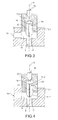
- control device In the application to the supply of cooling nozzles, the control device is normally open (state represented on the figure 3 ), allowing a supply of sprinklers. For other applications, it can be in a normally closed state, the power supply being interrupted.
- the needle 16 interrupts the flow of the pilot chamber 18 to the second portion 12.2 of the secondary conduit 12. Due to the permanent communication between the inlet 8 and the control chamber 18 and the closed state of the needle, the oil pressure in the control chamber 18 is equal to the oil pressure at the inlet 8.
- the surface of the second longitudinal end 14.2 of the movable shutter 14 on which the oil of the chamber of control 18 being greater than the surface of the first longitudinal end 14.1 of the movable shutter 14 on which the oil is applied to the inlet 8, the force exerted by the oil in the control chamber 18 on the shutter mobile 14 plate the movable shutter 14 on the valve seat 17.
- the communication between the input 8 and the output 10 is interrupted. Sprinklers are not supplied with oil.
- the control needle When it is desired to supply the oil cooling nozzle, the control needle is slid so as to allow communication between the pilot chamber 18 and the second portion 12.2 of the secondary duct ( figure 2 ). This communication causes a flow of the fluid contained in the control chamber to the outlet 10 by the second portion 12.2. Moreover, the flow rate through the second portion 12.2 is greater than that of the inlet 8 in the control chamber 18, the pressure in the control chamber 18 decreases due to the flow through the second portion 12.2 in the direction of the discharge outlet 10, and thus the pressure decreases from the inlet pressure to the outlet pressure.
- the oil pressure at the supply inlet 8 applying to the first end of the movable shutter is then greater than that applied to the second end of the movable shutter 14 in the control chamber 18 and is such that the force applied to the first longitudinal end 14.1 of the movable shutter 14 by the pressurized oil is greater than that applied to the second longitudinal end 14.2 of the movable shutter 14 by the oil contained in the 18, the movable shutter 14 then slides in the first zone 12.1 of the secondary duct 12 in a direction of decreasing the volume of the control chamber 18.
- the movable shutter deviates from the valve seat 17 due to the dynamic pressure and the static pressure, then allowing a flow of oil from the supply inlet 8 to the supply outlet 10 through the main pipe 11 ( figure 3 ).
- the control needle When it is decided to interrupt the supply of the oil nozzles, the control needle is slid so as to interrupt again the communication between the first portion 12.1 and the second portion 12.2 of the secondary duct 12 ( figure 4 ).
- the control chamber 18 is always supplied with oil through the passage through the movable shutter 14, but the oil is no longer removed by the second portion 12.2.
- the pressure in the pilot chamber 18 increases until the value of the pressure is reached.
- the flow between the supply inlet 8 and the exhaust outlet 10 is then interrupted again ( figure 1 ).
- the opening and closing of the closure means are in all or nothing, but it can be provided for a partial opening or closing of the communication between the control chamber 18 and the second portion 12.2 of the secondary conduit 12 by providing proportional opening means of the closure means.
- a movable shutter of large size and / or having a large stroke can be implemented while maintaining closure means having a stroke and a very small size, since the control of the shutter is assisted by the pressure prevailing in the control chamber.
- the control device can then have a great compactness.
- control device is simplified in that it requires only a secondary channel between the supply inlet and the exhaust outlet and does not require venting at atmospheric pressure. Its cost price is then reduced.
- this device is very easily integrable with existing cooling circuits.
- the power control device is particularly suitable for controlling the supply of one or more piston cooling nozzles for an internal combustion engine. But it will be understood that the control device according to the present invention can adapt to all systems using fluids and requiring control of the fluid supply.
Landscapes
- Engineering & Computer Science (AREA)
- General Engineering & Computer Science (AREA)
- Mechanical Engineering (AREA)
- Chemical & Material Sciences (AREA)
- Combustion & Propulsion (AREA)
- Fluid-Driven Valves (AREA)
- Lubrication Of Internal Combustion Engines (AREA)
- Valve Device For Special Equipments (AREA)
- Pipeline Systems (AREA)
- Fuel-Injection Apparatus (AREA)
Abstract
Description
La présente invention se rapporte à un dispositif de commande de l'alimentation d'un système avec un fluide, par exemple de l'alimentation de gicleurs de refroidissement des pistons d'un moteur à combustion interne avec de l'huile.The present invention relates to a device for controlling the supply of a system with a fluid, for example the supply of pistons cooling jets of an internal combustion engine with oil.
Le document
Ce dispositif donne entière satisfaction. La réduction des coûts de revient et une simplification des systèmes sont recherchées, en particulier dans le domaine automobile.This device gives complete satisfaction. The reduction of costs and simplification of systems are sought, especially in the automotive field.
C'est par conséquent le but de la présente invention d'offrir un dispositif de commande de l'alimentation d'un système avec un fluide, de réalisation simplifiée et offrant un coût de revient réduit par rapport aux dispositifs de commande de l'état de la technique.It is therefore the object of the present invention to provide a device for controlling the supply of a system with a fluid, simplified embodiment and offering a reduced cost compared to the control devices of the state. of the technique.
Le but précédemment énoncé est atteint par un dispositif de commande comportant une entrée d'alimentation en fluide sous pression, une sortie d'évacuation vers le système à alimenter avec du fluide, un conduit principal entre l'entrée d'alimentation et la sortie d'évacuation, un obturateur mobile interposé entre l'entrée et la sortie et apte à interrompre ou autoriser la communication entre l'entrée et la sortie par le conduit principal, un canal secondaire reliant l'entrée d'alimentation et la sortie d'évacuation, des moyens d'obturation disposés dans le conduit secondaire aptes à obturer sur commande ledit conduit secondaire, l'obturateur mobile délimitant dans le conduit secondaire avec les moyens d'obturation une chambre de pilotage qui est en permanence en communication fluidique avec l'entrée d'alimentation. Lorsque les moyens d'obturation obturent l'écoulement dans le canal secondaire, le fluide applique un effort sur l'obturateur mobile de sorte qu'il obture le conduit principal. Lorsque les moyens d'obturation autorisent l'écoulement dans le canal secondaire, l'obturateur se déplace de sorte à autoriser l'écoulement dans le canal principal.The previously stated purpose is achieved by a control device having a pressurized fluid supply inlet, a discharge outlet to the system to be supplied with fluid, a main conduit between the supply inlet and the outlet of evacuation, a movable shutter interposed between the inlet and the outlet and able to interrupt or allow communication between the inlet and the outlet via the main duct, a secondary channel connecting the supply inlet and the discharge outlet , closing means arranged in the secondary duct capable of shutting off on command said secondary duct, the movable shutter delimiting in the secondary duct with the closure means a control chamber which is permanently in fluid communication with the inlet power. When the sealing means seal the flow in the secondary channel, the fluid applies a force on the movable shutter so that it closes the main conduit. When the shutter means allow flow in the secondary channel, the shutter moves to allow flow into the main channel.
En d'autres termes, on réalise un dispositif de commande dans lequel on utilise la pression du fluide pour assister la commande, ce qui permet de réduire de manière sensible la taille de l'actionneur des moyens d'obturation. On peut mettre en oeuvre un obturateur de taille importante, notamment de section importante et/ou se déplaçant sur une course importante en utilisant un actionneur pour les moyens d'obturation de petite taille, par exemple une électrovanne de petite taille.In other words, there is provided a control device in which the pressure of the fluid is used to assist the control, thereby significantly reducing the size of the actuator shutter means. It is possible to implement a shutter of large size, in particular of large section and / or moving over a large stroke by using an actuator for the small shutter means, for example a small solenoid valve.
En outre, ce dispositif est simplifié puisqu'il ne requiert pas d'évent relié à la pression atmosphérique.In addition, this device is simplified since it does not require a vent connected to atmospheric pressure.
La commande des moyens obturateurs montés dans le canal secondaire peut être en tout ou rien ou proportionnel permettant alors une ouverture, une fermeture partielle du canal secondaire pour obtenir des positions d'ouverture et de fermeture partielles du dispositif de commande et donc une alimentation modulée des gicleurs ou de tout autre dispositif alimenté.Control shutter means mounted in the secondary channel may be all or nothing or proportional allowing then an opening, a partial closure of the secondary channel to obtain partial opening and closing positions of the control device and therefore a modulated supply of sprinklers or any other powered device.
La présente invention a alors pour objet un dispositif de commande de l'alimentation d'un système à partir d'une source de fluide sous pression comportant une entrée d'alimentation en fluide sous pression, une sortie d'évacuation du fluide sous pression, un conduit principal reliant l'entrée d'alimentation et la sortie d'évacuation, et des moyens de commande comportant :
- un conduit secondaire reliant l'entrée d'alimentation à la sortie d'évacuation,
- un obturateur mobile apte à interrompre l'écoulement dans le conduit principal, ledit obturateur mobile comportant une première extrémité et une deuxième extrémité, la première extrémité de l'obturateur mobile étant destinée à être soumise à la pression du fluide au niveau de l'entrée d'alimentation, l'obturateur mobile reposant sur un siège de clapet par sa première extrémité dans un état d'interruption de la communication entre l'entrée d'alimentation et la sortie d'évacuation,
- des moyens d'obturation aptes à interrompre l'écoulement dans le conduit secondaire,
- une chambre de pilotage délimitée par la deuxième extrémité de l'obturateur mobile et les moyens d'obturation,
- une communication permanente entre la chambre de pilotage et l'entrée d'alimentation,
- a secondary duct connecting the supply inlet to the discharge outlet,
- a movable shutter capable of interrupting the flow in the main pipe, said movable shutter having a first end and a second end, the first end of the movable shutter being intended to be subjected to the pressure of the fluid at the inlet supplying the mobile shutter resting on a valve seat by its first end in a state of interruption of the communication between the supply inlet and the discharge outlet,
- shutter means capable of interrupting the flow in the secondary duct,
- a pilot chamber delimited by the second end of the movable shutter and the shutter means,
- permanent communication between the control chamber and the feed inlet,
Par exemple, l'obturateur mobile comporte un passage traversant reliant sa première extrémité à sa deuxième extrémité assurant la communication permanente entre la chambre de pilotage et l'entrée d'alimentation.For example, the movable shutter has a through passage connecting its first end to its second end ensuring the permanent communication between the control chamber and the feed inlet.
Les moyens obturateurs peuvent comporter par exemple un élément d'obturation et un actionneur déplaçant ledit élément d'obturation entre une position fermée et une position ouverte et inversement.The shutter means may comprise for example a shutter member and an actuator moving said shutter member between a closed position and an open position and vice versa.
L'élément d'obturation peut être un pointeau de commande.The shutter member may be a control pin.
Dans un exemple de réalisation, l'actionneur est un actionneur en tout ou rien.In an exemplary embodiment, the actuator is an all-or-nothing actuator.
Dans un autre exemple de réalisation, l'actionneur est un actionneur proportionnel.In another embodiment, the actuator is a proportional actuator.
De manière avantageuse, les moyens d'obturation sont formés par une électrovanne.Advantageously, the closure means are formed by a solenoid valve.
La présente invention a également pour objet un système de refroidissement d'au moins un piston d'un moteur à combustion interne comportant au moins un dispositif de commande selon la présente invention, l'entrée d'alimentation du dispositif de commande étant connectée à une source d'huile sous pression et la sortie d'évacuation étant connectée à au moins un gicleur de refroidissement.The present invention also relates to a cooling system of at least one piston of an internal combustion engine comprising at least one control device according to the present invention, the supply input of the control device being connected to a pressurized oil source and the exhaust outlet being connected to at least one cooling nozzle.
La présente invention sera mieux comprise à l'aide de la description qui va suivre et des dessins en annexe sur lesquels :
- la
figure 1 est une vue en coupe schématique d'un dispositif de commande selon un exemple de réalisation dans une position de non alimentation des gicleurs, - la
figure 2 est une vue en coupe schématique du dispositif lafigure 1 dans une position intermédiaire en vue de l'alimentation des gicleurs, - la
figure 3 est une vue en coupe schématique du dispositif de lafigure 1 dans une position d'alimentation des gicleurs, - la
figure 4 , est une vue en coupe schématique du dispositif de lafigure 1 dans une position en vue de l'interruption de l'alimentation des gicleurs.
- the
figure 1 is a schematic sectional view of a control device according to an exemplary embodiment in a non-feeding position of the nozzles, - the
figure 2 is a schematic sectional view of the devicefigure 1 in an intermediate position for feeding sprinklers, - the
figure 3 is a schematic sectional view of the device of thefigure 1 in a sprinkler feed position, - the
figure 4 , is a schematic sectional view of the device of thefigure 1 in a position to interrupt the supply of sprinklers.
Dans la description qui va suivre, le dispositif de commande sera appliqué à l'alimentation des gicleurs de refroidissement de pistons d'un moteur à combustion interne. Cependant la présente invention s'applique à tous les domaines utilisant des fluides et nécessitant une commande de leur alimentation. En outre, nous utiliserons, à des fins de simplification, le terme « huile » pour désigner le fluide circulant à travers le dispositif de commande, mais il sera compris que la présente invention ne se limite pas à l'alimentation d'huile que tout autre fluide peut être mis en oeuvre.In the following description, the control device will be applied to the supply of the piston cooling jets of an internal combustion engine. However, the present invention applies to all areas using fluids and requiring control of their supply. In addition, for purposes of simplification we will use the term "oil" to refer to the fluid flowing through the control device, but it will be understood that the present invention is not limited to the supply of oil that any other fluid can be implemented.
Le dispositif de commande 2 représenté sur les
Dans le cas de la commande de l'alimentation en huile des gicleurs, le dispositif de commande est destiné à être fixé sur le carter moteur.In the case of the control of the oil supply of the nozzles, the control device is intended to be fixed on the crankcase.
Le dispositif de commande comporte une entrée d'alimentation 8, désignée par la suite entrée, et une sortie d'évacuation 10, désignée par la suite sortie. L'entrée 8 est destinée à être connectée à la source d'huile sous pression (non représentée), par exemple une pompe à huile, et la sortie 10 est destinée à être connectée à au moins un gicleur de refroidissement (non représenté) L'entrée 8 et la sortie 10 sont reliées par un conduit principal 11.The control device has a
Le dispositif de commande comporte en outre, interposés entre 8 et la sortie 10, des moyens de commande de la communication fluidique entre l'entrée 8 et la sortie 10.The control device further comprises, interposed between 8 and the
Les moyens de commande sont disposés dans le conduit principal 11 entre l'entrée 8 et la sortie 10 de sorte à commander la communication entre l'entrée 8 et la sortie 10. Les moyens de commande comportent un conduit secondaire 12 reliant l'entrée 8 et la sortie 10, des moyens d'obturation 16 disposés dans le conduit secondaire 12, délimitant une première portion 12.1 située entre l'entrée 8 et les moyens d'obturation 16 et une deuxième portion 12.2 située entre les moyens d'obturation 16 et la sortie d'évacuation 10.The control means are arranged in the
Les moyens de commande comportent un obturateur mobile 14 en translation dans la première portion 12.1, l'obturateur mobile 14 étant destiné à reposer sur un siège de clapet 17 bordant l'entrée 8. L'obturateur mobile 14 présente un axe longitudinal X et est mobile le long de son axe longitudinal dans la première portion 12.2.The control means comprise a
Une chambre de pilotage 18 est ménagée entre l'obturateur mobile 14 et les moyens d'obturation 16.A
La chambre de pilotage 18 est en permanence en communication avec l'entrée 8. Dans l'exemple représenté, l'obturateur mobile 14 comporte un passage 20 assurant une communication permanente entre l'entrée 8 et la chambre de pilotage 18. Dans l'exemple représenté, le passage est coaxial à l'axe de l'obturateur mobile 14, mais il pourrait être décalé par rapport à l'axe de l'obturateur.The
La deuxième portion 12.2 du conduit secondaire 12 est telle que le débit de la chambre de pilotage 18 vers la sortie 10 est supérieure à celui de l'entrée 8 vers la chambre de pilotage 18. Par exemple, la section de passage de la deuxième portion 12.2 du conduit secondaire 12 est supérieure à celle du passage à travers l'obturateur mobile 14.The second portion 12.2 of the
Les moyens d'obturation 16 sont, dans l'exemple représenté, formés par un pointeau de commande déplaçable en translation par un actionneur. Les moyens d'obturation peuvent par exemple être formés par une électrovanne. Tous les moyens permettant d'interrompre ou d'autoriser l'écoulement sur commande peuvent être mis en oeuvre. Par exemple on peu envisager de mettre en oeuvre un clapet actionné par un actionneur piézoélectrique ou pneumatique. Dans d'autres applications, des moyens d'obturation à commande manuelle peuvent être envisagés.The sealing means 16 are, in the example shown, formed by a control pin movable in translation by an actuator. The sealing means may for example be formed by a solenoid valve. Any means for interrupting or allowing the flow to order can be implemented. For example, it is possible to envisage using a valve actuated by a piezoelectric or pneumatic actuator. In other applications, manually controlled shutter means can be envisaged.
L'obturateur mobile 14 comporte une première extrémité 14.1 longitudinale soumise à la pression du fluide à l'entrée 8, et une deuxième extrémité longitudinale 14.2 soumise à la pression du fluide dans la chambre de pilotage 18. La surface de la deuxième extrémité longitudinale 14.2 voyant l'huile sous pression est supérieure à la surface de la première extrémité longitudinale 14.1 voyant le fluide sous pression de sorte que, lorsque la même pression règne à l'entrée 8 et dans la chambre de pilotage 18 l'obturateur mobile 14 est repoussée contre son siège 17 et interrompt la communication entre l'entrée 8 et la sortie 10.The
Dans l'exemple représenté, la première extrémité 14.1 a une forme tronconique, et la surface de la première extrémité 14.1 de l'obturateur voyant le fluide lorsque l'obturateur est écarté de son siège est la même surface que celle de la deuxième extrémité de l'obturateur. Cependant, du fait de l'écoulement de l'huile et des pertes de charge, la pression dans le conduit principal 11 est inférieure à celle dans la chambre de pilotage 18 qui est à la pression de l'entrée 8. Une obturateur ayant une autre forme ne sort pas duc cadre de la présente invention.In the example shown, the first end 14.1 has a frustoconical shape, and the surface of the first end 14.1 of the shutter seeing the fluid when the shutter is spaced from its seat is the same surface as that of the second end of the shutter. However, because of the flow of the oil and the pressure drops, the pressure in the
Le fonctionnement du dispositif de commande selon l'invention va maintenant être décrit.The operation of the control device according to the invention will now be described.
Dans l'application à l'alimentation de gicleurs de refroidissement, le dispositif de commande est normalement ouvert (état représenté sur la
Dans une position d'interruption de l'alimentation telle que représentée sur la
Lorsqu'on souhaite alimenter le gicleur de refroidissement en huile, le pointeau de commande est coulissé de sorte à permettre une communication entre la chambre de pilotage 18 et la deuxième portion 12.2 du conduit secondaire (
Lorsqu'il est décidé d'interrompre l'alimentation des gicleurs en huile, le pointeau de commande est coulissé de sorte à venir interrompre à nouveau la communication entre la première portion 12.1 et la deuxième portion 12.2 du conduit secondaire 12 (
Dans l'exemple décrit, l'ouverture et la fermeture des moyens d'obturation sont en tout ou rien, mais on peut prévoir une ouverture ou une fermeture partielle de la communication entre la chambre de pilotage 18 et la deuxième portion 12.2 du conduit secondaire 12 en prévoyant des moyens d'ouverture proportionnels des moyens d'obturation.In the example described, the opening and closing of the closure means are in all or nothing, but it can be provided for a partial opening or closing of the communication between the
Grâce à l'invention, un obturateur mobile de grande taille et/ou ayant un course importante peut être mis en oeuvre tout en conservant des moyens d'obturation présentant une course et une taille très faible, puisque la commande de l'obturateur est assistée par la pression régnant dans la chambre de pilotage. Le dispositif de commande peut alors présenter une grande compacité.Thanks to the invention, a movable shutter of large size and / or having a large stroke can be implemented while maintaining closure means having a stroke and a very small size, since the control of the shutter is assisted by the pressure prevailing in the control chamber. The control device can then have a great compactness.
En outre, le dispositif de commande est de réalisation simplifiée, puisqu'il ne requiert qu'un canal secondaire entre l'entrée d'alimentation et la sortie d'évacuation et ne requiert pas d'évent à la pression atmosphérique. Son coût de revient en est alors réduit.In addition, the control device is simplified in that it requires only a secondary channel between the supply inlet and the exhaust outlet and does not require venting at atmospheric pressure. Its cost price is then reduced.
En outre ce dispositif est très facilement intégrable aux circuits de refroidissement existants.In addition, this device is very easily integrable with existing cooling circuits.
Le dispositif de commande d'alimentation est particulièrement adapté à la commande de l'alimentation de un ou plusieurs gicleurs de refroidissement de piston pour moteur à combustion interne. Mais il sera compris que le dispositif de commande selon la présente invention peut s'adapter à tous systèmes mettant en oeuvre des fluides et requérant une commande de l'alimentation en fluide.The power control device is particularly suitable for controlling the supply of one or more piston cooling nozzles for an internal combustion engine. But it will be understood that the control device according to the present invention can adapt to all systems using fluids and requiring control of the fluid supply.
Claims (8)
les surfaces des première (14.1) et deuxième (14.2) extrémités s de l'obturateur mobile (14) sur lesquelles s'applique le fluide sous pression et la section de passage de la deuxième portion (12.1) du conduit secondaire sont telles que, dans un état de fermeture des moyens d'obturation, l'obturateur mobile (14) est maintenu en appui sur son siège de clapet (17) de sorte à interrompre la circulation du fluide entre l'entrée d'alimentation (8) et la sortie d'évacuation (10), et, dans un état d'ouverture des moyens d'obturation, l'obturateur mobile est écarté de son siège de clapet (17) autorisant l'écoulement entre l'entrée d'alimentation (8) et la sortie d'évacuation (10).
the surfaces of the first (14.1) and second (14.2) ends s of the movable shutter (14) to which the pressurized fluid is applied and the passage section of the second portion (12.1) of the secondary conduit are such that, in a closing state of the closure means, the movable shutter (14) is held in abutment on its valve seat (17) so as to interrupt the flow of fluid between the supply inlet (8) and the exit discharge valve (10), and in an open state of the closure means the movable shutter is moved away from its valve seat (17) allowing flow between the supply inlet (8) and the evacuation outlet (10).
Priority Applications (8)
| Application Number | Priority Date | Filing Date | Title |
|---|---|---|---|
| ES13305281.1T ES2559527T3 (en) | 2013-03-13 | 2013-03-13 | Device for controlling the supply of a system with a fluid |
| EP13305281.1A EP2778364B1 (en) | 2013-03-13 | 2013-03-13 | Device for controlling the power supply of a system with a fluid |
| DE13305281.1T DE13305281T1 (en) | 2013-03-13 | 2013-03-13 | Control device for feeding a liquid into a system |
| BR102014005704A BR102014005704A2 (en) | 2013-03-13 | 2014-03-12 | control device and system for cooling at least one piston of an internal combustion engine |
| US14/205,987 US20140264101A1 (en) | 2013-03-13 | 2014-03-12 | Device for Controlling the Fluid Supply of a System |
| JP2014048491A JP2014177942A (en) | 2013-03-13 | 2014-03-12 | Device for controlling fluid supply of system |
| KR1020140029938A KR20140112459A (en) | 2013-03-13 | 2014-03-13 | Device for controlling the fluid supply of a system |
| CN201410092864.0A CN104047698A (en) | 2013-03-13 | 2014-03-13 | Device for Controlling the Fluid Supply of a System |
Applications Claiming Priority (1)
| Application Number | Priority Date | Filing Date | Title |
|---|---|---|---|
| EP13305281.1A EP2778364B1 (en) | 2013-03-13 | 2013-03-13 | Device for controlling the power supply of a system with a fluid |
Publications (3)
| Publication Number | Publication Date |
|---|---|
| EP2778364A1 true EP2778364A1 (en) | 2014-09-17 |
| EP2778364A8 EP2778364A8 (en) | 2014-12-03 |
| EP2778364B1 EP2778364B1 (en) | 2015-10-14 |
Family
ID=48083073
Family Applications (1)
| Application Number | Title | Priority Date | Filing Date |
|---|---|---|---|
| EP13305281.1A Active EP2778364B1 (en) | 2013-03-13 | 2013-03-13 | Device for controlling the power supply of a system with a fluid |
Country Status (7)
| Country | Link |
|---|---|
| US (1) | US20140264101A1 (en) |
| EP (1) | EP2778364B1 (en) |
| JP (1) | JP2014177942A (en) |
| KR (1) | KR20140112459A (en) |
| CN (1) | CN104047698A (en) |
| BR (1) | BR102014005704A2 (en) |
| ES (1) | ES2559527T3 (en) |
Cited By (3)
| Publication number | Priority date | Publication date | Assignee | Title |
|---|---|---|---|---|
| WO2017054970A1 (en) * | 2015-10-02 | 2017-04-06 | Kendrion (Markdorf) Gmbh | Cooling circuit arrangement and method for cooling an engine |
| DE102016205819A1 (en) | 2016-04-07 | 2017-10-12 | Schaeffler Technologies AG & Co. KG | Device for cooling a piston of an internal combustion engine |
| CN113544422A (en) * | 2019-03-14 | 2021-10-22 | 舍弗勒技术股份两合公司 | Pilot controlled coolant valve |
Families Citing this family (11)
| Publication number | Priority date | Publication date | Assignee | Title |
|---|---|---|---|---|
| DE102012200126A1 (en) | 2012-01-05 | 2013-07-11 | Robert Bosch Gmbh | Driver assistance service |
| FR3004489B1 (en) | 2013-04-11 | 2017-04-28 | Bontaz Centre R & D | COOLING DEVICE FOR A REDUCED INTERNAL COMBUSTION ENGINE AND METHOD FOR MANUFACTURING SUCH A DEVICE |
| CN104456625B (en) * | 2014-11-11 | 2017-11-07 | 北京华清燃气轮机与煤气化联合循环工程技术有限公司 | The air intake structure of gas turbine fuel nozzles |
| CN104989854B (en) * | 2015-07-15 | 2017-09-26 | 李国栋 | The vertical automatic safety device of pipeline burst |
| DE102016113003B4 (en) | 2016-07-14 | 2024-02-08 | Wagner Gmbh & Co. Kg | Control valve for supplying one or more nozzles with a pressure fluid |
| CN110832239B (en) * | 2017-06-09 | 2022-03-04 | 萨尔瓦托雷·布福 | Safety valve for a hydraulic system |
| DE102017122271A1 (en) * | 2017-09-26 | 2019-03-28 | Schaeffler Technologies AG & Co. KG | Switching unit for a thermal management module of a motor vehicle |
| DE102019120282A1 (en) * | 2019-07-26 | 2021-01-28 | Schaeffler Technologies AG & Co. KG | Lifting solenoid valve with locking gate for energy-free holding of all positions including intermediate positions |
| US11933419B2 (en) * | 2019-09-06 | 2024-03-19 | Danfoss A/S | Low power hydraulic valves with increased rate-of-flow |
| DE102020119472A1 (en) | 2020-07-23 | 2022-01-27 | Schaeffler Technologies AG & Co. KG | Pilot operated coolant valve |
| CN115573965B (en) * | 2022-12-07 | 2023-03-21 | 太原理工大学 | Multifunctional electro-hydraulic flow control valve and flow control method |
Citations (4)
| Publication number | Priority date | Publication date | Assignee | Title |
|---|---|---|---|---|
| US4114571A (en) * | 1975-10-16 | 1978-09-19 | Max Ruf | Means for controlling the oil cooling of the piston of a piston engine |
| US5522358A (en) * | 1995-08-31 | 1996-06-04 | Caterpillar Inc. | Fluid controlling system for an engine |
| JP2001280109A (en) * | 2000-03-31 | 2001-10-10 | Isuzu Motors Ltd | Hydraulic valve system |
| FR2935771A1 (en) | 2008-09-09 | 2010-03-12 | Bontaz Centre Sa | DEVICE FOR CONTROLLING THE SUPPLY OF A SYSTEM WITH A FLUID |
Family Cites Families (12)
| Publication number | Priority date | Publication date | Assignee | Title |
|---|---|---|---|---|
| US1005703A (en) * | 1911-05-23 | 1911-10-10 | Gustave W Goeddel | Automatic flush-valve. |
| US3757821A (en) * | 1971-01-13 | 1973-09-11 | K Fujiwara | Disk type electromagnetic valve |
| JPS5325965B2 (en) * | 1972-03-18 | 1978-07-29 | ||
| JPS61166284U (en) * | 1985-04-05 | 1986-10-15 | ||
| US5738332A (en) * | 1995-10-20 | 1998-04-14 | Perez Corbalan; Sergio | Flow valve operated by flow transfer means which regulate small flows of control |
| JP3069515B2 (en) * | 1995-11-24 | 2000-07-24 | 新キャタピラー三菱株式会社 | Electromagnetic proportional relief valve |
| US5676342A (en) * | 1996-06-17 | 1997-10-14 | Automatic Switch Company | Proportional flow valve with diaphragm pressure member |
| SE519673C2 (en) * | 2000-12-22 | 2003-03-25 | Atlas Copco Tools Ab | Speed controller for a pneumatic rotary motor |
| CN1170077C (en) * | 2002-05-24 | 2004-10-06 | 浙江大学 | Control valve of high-pressure pneumatic switch |
| WO2008078140A1 (en) * | 2006-12-27 | 2008-07-03 | Renault Trucks | Nozzle, lubrication system and internal combustion engine comprising such a nozzle or such a system |
| JP2011163508A (en) * | 2010-02-12 | 2011-08-25 | Toyota Motor Corp | Hydraulic control device |
| CN202691198U (en) * | 2012-07-24 | 2013-01-23 | 温州市中意空分设备有限公司 | Gas pressure reducing valve |
-
2013
- 2013-03-13 ES ES13305281.1T patent/ES2559527T3/en active Active
- 2013-03-13 EP EP13305281.1A patent/EP2778364B1/en active Active
-
2014
- 2014-03-12 BR BR102014005704A patent/BR102014005704A2/en not_active IP Right Cessation
- 2014-03-12 JP JP2014048491A patent/JP2014177942A/en active Pending
- 2014-03-12 US US14/205,987 patent/US20140264101A1/en not_active Abandoned
- 2014-03-13 CN CN201410092864.0A patent/CN104047698A/en active Pending
- 2014-03-13 KR KR1020140029938A patent/KR20140112459A/en not_active Application Discontinuation
Patent Citations (4)
| Publication number | Priority date | Publication date | Assignee | Title |
|---|---|---|---|---|
| US4114571A (en) * | 1975-10-16 | 1978-09-19 | Max Ruf | Means for controlling the oil cooling of the piston of a piston engine |
| US5522358A (en) * | 1995-08-31 | 1996-06-04 | Caterpillar Inc. | Fluid controlling system for an engine |
| JP2001280109A (en) * | 2000-03-31 | 2001-10-10 | Isuzu Motors Ltd | Hydraulic valve system |
| FR2935771A1 (en) | 2008-09-09 | 2010-03-12 | Bontaz Centre Sa | DEVICE FOR CONTROLLING THE SUPPLY OF A SYSTEM WITH A FLUID |
Cited By (6)
| Publication number | Priority date | Publication date | Assignee | Title |
|---|---|---|---|---|
| WO2017054970A1 (en) * | 2015-10-02 | 2017-04-06 | Kendrion (Markdorf) Gmbh | Cooling circuit arrangement and method for cooling an engine |
| DE102016205819A1 (en) | 2016-04-07 | 2017-10-12 | Schaeffler Technologies AG & Co. KG | Device for cooling a piston of an internal combustion engine |
| WO2017174058A1 (en) | 2016-04-07 | 2017-10-12 | Schaeffler Technologies AG & Co. KG | Device for cooling a piston of an internal combustion engine |
| DE102016205819B4 (en) | 2016-04-07 | 2019-05-23 | Schaeffler Technologies AG & Co. KG | Device for controlling a hydraulic fluid supply of an internal combustion engine |
| CN113544422A (en) * | 2019-03-14 | 2021-10-22 | 舍弗勒技术股份两合公司 | Pilot controlled coolant valve |
| CN113544422B (en) * | 2019-03-14 | 2023-08-15 | 舍弗勒技术股份两合公司 | Pilot-controlled coolant valve |
Also Published As
| Publication number | Publication date |
|---|---|
| US20140264101A1 (en) | 2014-09-18 |
| KR20140112459A (en) | 2014-09-23 |
| EP2778364B1 (en) | 2015-10-14 |
| EP2778364A8 (en) | 2014-12-03 |
| ES2559527T3 (en) | 2016-02-12 |
| CN104047698A (en) | 2014-09-17 |
| JP2014177942A (en) | 2014-09-25 |
| BR102014005704A2 (en) | 2015-12-15 |
Similar Documents
| Publication | Publication Date | Title |
|---|---|---|
| EP2778364B1 (en) | Device for controlling the power supply of a system with a fluid | |
| EP2326811B1 (en) | Device for controlling the fluid supply of a system | |
| EP2984314B1 (en) | Oil jetting nozzle for cooling a piston of an internal combustion engine | |
| EP2006587B1 (en) | Watertight valve system | |
| EP3365548B1 (en) | Fuel injector | |
| WO2018019801A1 (en) | Ventilation flow rate regulator for a pressurised tank of a vehicle | |
| FR2781032A1 (en) | Device for regulation of water outlet from a tap or shower has an additional valve to gradually reduce any high-pressure buildup caused by the tap being closed too quickly | |
| FR2998025A1 (en) | VALVE | |
| WO2017207902A1 (en) | Chamber between an inlet nozzle and a sealing member, for a turbomachine injector | |
| FR3079879A1 (en) | DISCHARGE VALVE WITH REGULATED OPENING | |
| EP1312864B1 (en) | Dosing device for turbomachine fuel injector | |
| FR3014488A1 (en) | VALVE FOR FUEL CIRCUIT OF AN AIRCRAFT ENGINE | |
| EP3486483B1 (en) | Pumping system comprising a pneumatic pump and a valve for controlling the compressed gas supply to the pump | |
| EP3098403B1 (en) | Device for controlling a pressurised fluid supply | |
| FR2555700A1 (en) | PRESSURE VALVE | |
| FR2651341A1 (en) | Flow rate or pressure regulator | |
| FR2582074A1 (en) | BRAKE PRESSURE CONTROL VALVE DEVICE | |
| FR2955170A1 (en) | Gas expander integrated tap for use in pressurized gas cylinder, has push-valve and pressure valve arranged in same housing of body, where push-valve is selectively moved independent of pressure valve for actuating insulation valve | |
| EP3775645B1 (en) | Improved regulating valve with integrated purge function | |
| EP2829717A1 (en) | Fuel injector | |
| FR3079875A1 (en) | TURBOMACHINE DISCHARGE DEVICE COMPRISING A VALVE | |
| FR3037377A1 (en) | DYNAMIC PRESSURE REGULATOR | |
| FR2870914A1 (en) | Hydraulic valve installation for use in hydrostatic driving system, has damping side outlet functioning for pressure limitation function of installation and not functioning at opening and closing of installation for reaspiration function | |
| EP3146191B1 (en) | Improved flow-control device with reduced weight | |
| FR2752902A1 (en) | Regulating valve for drinking water distribution systems |
Legal Events
| Date | Code | Title | Description |
|---|---|---|---|
| PUAI | Public reference made under article 153(3) epc to a published international application that has entered the european phase |
Free format text: ORIGINAL CODE: 0009012 |
|
| 17P | Request for examination filed |
Effective date: 20130313 |
|
| AK | Designated contracting states |
Kind code of ref document: A1 Designated state(s): AL AT BE BG CH CY CZ DE DK EE ES FI FR GB GR HR HU IE IS IT LI LT LU LV MC MK MT NL NO PL PT RO RS SE SI SK SM TR |
|
| AX | Request for extension of the european patent |
Extension state: BA ME |
|
| GBCC | Gb: corrected translation (of claims) filed (gb section 80(3)/1977) | ||
| REG | Reference to a national code |
Ref country code: DE Ref legal event code: R210 Ref document number: 602013003470 Country of ref document: DE Effective date: 20141106 Ref country code: DE Ref legal event code: R210 Effective date: 20141106 |
|
| RAP1 | Party data changed (applicant data changed or rights of an application transferred) |
Owner name: BONTAZ CENTRE R & D |
|
| R17P | Request for examination filed (corrected) |
Effective date: 20150309 |
|
| RBV | Designated contracting states (corrected) |
Designated state(s): AL AT BE BG CH CY CZ DE DK EE ES FI FR GB GR HR HU IE IS IT LI LT LU LV MC MK MT NL NO PL PT RO RS SE SI SK SM TR |
|
| GRAP | Despatch of communication of intention to grant a patent |
Free format text: ORIGINAL CODE: EPIDOSNIGR1 |
|
| INTG | Intention to grant announced |
Effective date: 20150508 |
|
| GRAS | Grant fee paid |
Free format text: ORIGINAL CODE: EPIDOSNIGR3 |
|
| GRAA | (expected) grant |
Free format text: ORIGINAL CODE: 0009210 |
|
| AK | Designated contracting states |
Kind code of ref document: B1 Designated state(s): AL AT BE BG CH CY CZ DE DK EE ES FI FR GB GR HR HU IE IS IT LI LT LU LV MC MK MT NL NO PL PT RO RS SE SI SK SM TR |
|
| REG | Reference to a national code |
Ref country code: GB Ref legal event code: FG4D Free format text: NOT ENGLISH |
|
| REG | Reference to a national code |
Ref country code: AT Ref legal event code: REF Ref document number: 755279 Country of ref document: AT Kind code of ref document: T Effective date: 20151015 Ref country code: CH Ref legal event code: EP |
|
| REG | Reference to a national code |
Ref country code: NL Ref legal event code: MP Effective date: 20151014 |
|
| REG | Reference to a national code |
Ref country code: IE Ref legal event code: FG4D Free format text: LANGUAGE OF EP DOCUMENT: FRENCH |
|
| REG | Reference to a national code |
Ref country code: DE Ref legal event code: R082 Ref document number: 602013003470 Country of ref document: DE Representative=s name: BETTEN & RESCH PATENT- UND RECHTSANWAELTE PART, DE Ref country code: DE Ref legal event code: R082 Ref document number: 602013003470 Country of ref document: DE |
|
| REG | Reference to a national code |
Ref country code: DE Ref legal event code: R096 Ref document number: 602013003470 Country of ref document: DE |
|
| REG | Reference to a national code |
Ref country code: SE Ref legal event code: TRGR |
|
| REG | Reference to a national code |
Ref country code: ES Ref legal event code: FG2A Ref document number: 2559527 Country of ref document: ES Kind code of ref document: T3 Effective date: 20160212 |
|
| REG | Reference to a national code |
Ref country code: LT Ref legal event code: MG4D |
|
| REG | Reference to a national code |
Ref country code: AT Ref legal event code: MK05 Ref document number: 755279 Country of ref document: AT Kind code of ref document: T Effective date: 20151014 |
|
| REG | Reference to a national code |
Ref country code: FR Ref legal event code: PLFP Year of fee payment: 4 |
|
| PG25 | Lapsed in a contracting state [announced via postgrant information from national office to epo] |
Ref country code: NL Free format text: LAPSE BECAUSE OF FAILURE TO SUBMIT A TRANSLATION OF THE DESCRIPTION OR TO PAY THE FEE WITHIN THE PRESCRIBED TIME-LIMIT Effective date: 20151014 Ref country code: HR Free format text: LAPSE BECAUSE OF FAILURE TO SUBMIT A TRANSLATION OF THE DESCRIPTION OR TO PAY THE FEE WITHIN THE PRESCRIBED TIME-LIMIT Effective date: 20151014 Ref country code: LT Free format text: LAPSE BECAUSE OF FAILURE TO SUBMIT A TRANSLATION OF THE DESCRIPTION OR TO PAY THE FEE WITHIN THE PRESCRIBED TIME-LIMIT Effective date: 20151014 Ref country code: NO Free format text: LAPSE BECAUSE OF FAILURE TO SUBMIT A TRANSLATION OF THE DESCRIPTION OR TO PAY THE FEE WITHIN THE PRESCRIBED TIME-LIMIT Effective date: 20160114 Ref country code: IS Free format text: LAPSE BECAUSE OF FAILURE TO SUBMIT A TRANSLATION OF THE DESCRIPTION OR TO PAY THE FEE WITHIN THE PRESCRIBED TIME-LIMIT Effective date: 20160214 |
|
| PG25 | Lapsed in a contracting state [announced via postgrant information from national office to epo] |
Ref country code: LV Free format text: LAPSE BECAUSE OF FAILURE TO SUBMIT A TRANSLATION OF THE DESCRIPTION OR TO PAY THE FEE WITHIN THE PRESCRIBED TIME-LIMIT Effective date: 20151014 Ref country code: GR Free format text: LAPSE BECAUSE OF FAILURE TO SUBMIT A TRANSLATION OF THE DESCRIPTION OR TO PAY THE FEE WITHIN THE PRESCRIBED TIME-LIMIT Effective date: 20160115 Ref country code: RS Free format text: LAPSE BECAUSE OF FAILURE TO SUBMIT A TRANSLATION OF THE DESCRIPTION OR TO PAY THE FEE WITHIN THE PRESCRIBED TIME-LIMIT Effective date: 20151014 Ref country code: AT Free format text: LAPSE BECAUSE OF FAILURE TO SUBMIT A TRANSLATION OF THE DESCRIPTION OR TO PAY THE FEE WITHIN THE PRESCRIBED TIME-LIMIT Effective date: 20151014 Ref country code: FI Free format text: LAPSE BECAUSE OF FAILURE TO SUBMIT A TRANSLATION OF THE DESCRIPTION OR TO PAY THE FEE WITHIN THE PRESCRIBED TIME-LIMIT Effective date: 20151014 Ref country code: PL Free format text: LAPSE BECAUSE OF FAILURE TO SUBMIT A TRANSLATION OF THE DESCRIPTION OR TO PAY THE FEE WITHIN THE PRESCRIBED TIME-LIMIT Effective date: 20151014 |
|
| REG | Reference to a national code |
Ref country code: DE Ref legal event code: R097 Ref document number: 602013003470 Country of ref document: DE |
|
| PLBE | No opposition filed within time limit |
Free format text: ORIGINAL CODE: 0009261 |
|
| STAA | Information on the status of an ep patent application or granted ep patent |
Free format text: STATUS: NO OPPOSITION FILED WITHIN TIME LIMIT |
|
| PG25 | Lapsed in a contracting state [announced via postgrant information from national office to epo] |
Ref country code: BE Free format text: LAPSE BECAUSE OF NON-PAYMENT OF DUE FEES Effective date: 20160331 Ref country code: EE Free format text: LAPSE BECAUSE OF FAILURE TO SUBMIT A TRANSLATION OF THE DESCRIPTION OR TO PAY THE FEE WITHIN THE PRESCRIBED TIME-LIMIT Effective date: 20151014 Ref country code: RO Free format text: LAPSE BECAUSE OF FAILURE TO SUBMIT A TRANSLATION OF THE DESCRIPTION OR TO PAY THE FEE WITHIN THE PRESCRIBED TIME-LIMIT Effective date: 20151014 Ref country code: SK Free format text: LAPSE BECAUSE OF FAILURE TO SUBMIT A TRANSLATION OF THE DESCRIPTION OR TO PAY THE FEE WITHIN THE PRESCRIBED TIME-LIMIT Effective date: 20151014 Ref country code: DK Free format text: LAPSE BECAUSE OF FAILURE TO SUBMIT A TRANSLATION OF THE DESCRIPTION OR TO PAY THE FEE WITHIN THE PRESCRIBED TIME-LIMIT Effective date: 20151014 Ref country code: SM Free format text: LAPSE BECAUSE OF FAILURE TO SUBMIT A TRANSLATION OF THE DESCRIPTION OR TO PAY THE FEE WITHIN THE PRESCRIBED TIME-LIMIT Effective date: 20151014 |
|
| 26N | No opposition filed |
Effective date: 20160715 |
|
| PG25 | Lapsed in a contracting state [announced via postgrant information from national office to epo] |
Ref country code: LU Free format text: LAPSE BECAUSE OF FAILURE TO SUBMIT A TRANSLATION OF THE DESCRIPTION OR TO PAY THE FEE WITHIN THE PRESCRIBED TIME-LIMIT Effective date: 20160313 Ref country code: MC Free format text: LAPSE BECAUSE OF FAILURE TO SUBMIT A TRANSLATION OF THE DESCRIPTION OR TO PAY THE FEE WITHIN THE PRESCRIBED TIME-LIMIT Effective date: 20151014 |
|
| REG | Reference to a national code |
Ref country code: CH Ref legal event code: PL |
|
| PG25 | Lapsed in a contracting state [announced via postgrant information from national office to epo] |
Ref country code: SI Free format text: LAPSE BECAUSE OF FAILURE TO SUBMIT A TRANSLATION OF THE DESCRIPTION OR TO PAY THE FEE WITHIN THE PRESCRIBED TIME-LIMIT Effective date: 20151014 |
|
| REG | Reference to a national code |
Ref country code: IE Ref legal event code: MM4A |
|
| PG25 | Lapsed in a contracting state [announced via postgrant information from national office to epo] |
Ref country code: CH Free format text: LAPSE BECAUSE OF NON-PAYMENT OF DUE FEES Effective date: 20160331 Ref country code: LI Free format text: LAPSE BECAUSE OF NON-PAYMENT OF DUE FEES Effective date: 20160331 Ref country code: IE Free format text: LAPSE BECAUSE OF NON-PAYMENT OF DUE FEES Effective date: 20160313 |
|
| REG | Reference to a national code |
Ref country code: FR Ref legal event code: PLFP Year of fee payment: 5 |
|
| PG25 | Lapsed in a contracting state [announced via postgrant information from national office to epo] |
Ref country code: MT Free format text: LAPSE BECAUSE OF FAILURE TO SUBMIT A TRANSLATION OF THE DESCRIPTION OR TO PAY THE FEE WITHIN THE PRESCRIBED TIME-LIMIT Effective date: 20151014 |
|
| REG | Reference to a national code |
Ref country code: FR Ref legal event code: PLFP Year of fee payment: 6 |
|
| PG25 | Lapsed in a contracting state [announced via postgrant information from national office to epo] |
Ref country code: HU Free format text: LAPSE BECAUSE OF FAILURE TO SUBMIT A TRANSLATION OF THE DESCRIPTION OR TO PAY THE FEE WITHIN THE PRESCRIBED TIME-LIMIT; INVALID AB INITIO Effective date: 20130313 |
|
| PG25 | Lapsed in a contracting state [announced via postgrant information from national office to epo] |
Ref country code: CY Free format text: LAPSE BECAUSE OF FAILURE TO SUBMIT A TRANSLATION OF THE DESCRIPTION OR TO PAY THE FEE WITHIN THE PRESCRIBED TIME-LIMIT Effective date: 20151014 Ref country code: PT Free format text: LAPSE BECAUSE OF FAILURE TO SUBMIT A TRANSLATION OF THE DESCRIPTION OR TO PAY THE FEE WITHIN THE PRESCRIBED TIME-LIMIT Effective date: 20151014 Ref country code: MK Free format text: LAPSE BECAUSE OF FAILURE TO SUBMIT A TRANSLATION OF THE DESCRIPTION OR TO PAY THE FEE WITHIN THE PRESCRIBED TIME-LIMIT Effective date: 20151014 Ref country code: TR Free format text: LAPSE BECAUSE OF FAILURE TO SUBMIT A TRANSLATION OF THE DESCRIPTION OR TO PAY THE FEE WITHIN THE PRESCRIBED TIME-LIMIT Effective date: 20151014 |
|
| PG25 | Lapsed in a contracting state [announced via postgrant information from national office to epo] |
Ref country code: BG Free format text: LAPSE BECAUSE OF FAILURE TO SUBMIT A TRANSLATION OF THE DESCRIPTION OR TO PAY THE FEE WITHIN THE PRESCRIBED TIME-LIMIT Effective date: 20151014 |
|
| PG25 | Lapsed in a contracting state [announced via postgrant information from national office to epo] |
Ref country code: AL Free format text: LAPSE BECAUSE OF FAILURE TO SUBMIT A TRANSLATION OF THE DESCRIPTION OR TO PAY THE FEE WITHIN THE PRESCRIBED TIME-LIMIT Effective date: 20151014 |
|
| REG | Reference to a national code |
Ref country code: GB Ref legal event code: 732E Free format text: REGISTERED BETWEEN 20230302 AND 20230308 |
|
| REG | Reference to a national code |
Ref country code: DE Ref legal event code: R081 Ref document number: 602013003470 Country of ref document: DE Owner name: BONTAZ CENTRE, FR Free format text: FORMER OWNER: BONTAZ CENTRE R&D, MARNAZ, FR |
|
| REG | Reference to a national code |
Ref country code: ES Ref legal event code: PC2A Owner name: BONTAZ CENTRE Effective date: 20230605 |
|
| PGFP | Annual fee paid to national office [announced via postgrant information from national office to epo] |
Ref country code: DE Payment date: 20240326 Year of fee payment: 12 Ref country code: CZ Payment date: 20240301 Year of fee payment: 12 Ref country code: GB Payment date: 20240329 Year of fee payment: 12 |
|
| PGFP | Annual fee paid to national office [announced via postgrant information from national office to epo] |
Ref country code: FR Payment date: 20240328 Year of fee payment: 12 |
|
| PGFP | Annual fee paid to national office [announced via postgrant information from national office to epo] |
Ref country code: ES Payment date: 20240423 Year of fee payment: 12 |
|
| PGFP | Annual fee paid to national office [announced via postgrant information from national office to epo] |
Ref country code: IT Payment date: 20240326 Year of fee payment: 12 |
|
| PGFP | Annual fee paid to national office [announced via postgrant information from national office to epo] |
Ref country code: SE Payment date: 20240402 Year of fee payment: 12 |