EP2778360B1 - Device for injecting a reducing agent into an exhaust line - Google Patents
Device for injecting a reducing agent into an exhaust line Download PDFInfo
- Publication number
- EP2778360B1 EP2778360B1 EP14158590.1A EP14158590A EP2778360B1 EP 2778360 B1 EP2778360 B1 EP 2778360B1 EP 14158590 A EP14158590 A EP 14158590A EP 2778360 B1 EP2778360 B1 EP 2778360B1
- Authority
- EP
- European Patent Office
- Prior art keywords
- heating
- reducing agent
- exhaust line
- heating means
- delivery
- Prior art date
- Legal status (The legal status is an assumption and is not a legal conclusion. Google has not performed a legal analysis and makes no representation as to the accuracy of the status listed.)
- Active
Links
- 239000003638 chemical reducing agent Substances 0.000 title claims description 40
- 238000010438 heat treatment Methods 0.000 claims description 50
- 238000002347 injection Methods 0.000 claims description 37
- 239000007924 injection Substances 0.000 claims description 37
- 239000003054 catalyst Substances 0.000 claims description 26
- 239000007789 gas Substances 0.000 claims description 22
- 238000002485 combustion reaction Methods 0.000 claims description 16
- 230000006698 induction Effects 0.000 claims description 5
- 230000000694 effects Effects 0.000 claims description 3
- 238000000034 method Methods 0.000 claims description 2
- 239000000470 constituent Substances 0.000 claims 1
- MWUXSHHQAYIFBG-UHFFFAOYSA-N nitrogen oxide Inorganic materials O=[N] MWUXSHHQAYIFBG-UHFFFAOYSA-N 0.000 description 24
- 238000011144 upstream manufacturing Methods 0.000 description 10
- QGZKDVFQNNGYKY-UHFFFAOYSA-N Ammonia Chemical compound N QGZKDVFQNNGYKY-UHFFFAOYSA-N 0.000 description 4
- XSQUKJJJFZCRTK-UHFFFAOYSA-N Urea Chemical compound NC(N)=O XSQUKJJJFZCRTK-UHFFFAOYSA-N 0.000 description 3
- 239000004202 carbamide Substances 0.000 description 3
- 238000000354 decomposition reaction Methods 0.000 description 3
- 229910021529 ammonia Inorganic materials 0.000 description 2
- 239000003795 chemical substances by application Substances 0.000 description 2
- XLYOFNOQVPJJNP-UHFFFAOYSA-N water Substances O XLYOFNOQVPJJNP-UHFFFAOYSA-N 0.000 description 2
- 241001080024 Telles Species 0.000 description 1
- 230000008878 coupling Effects 0.000 description 1
- 238000010168 coupling process Methods 0.000 description 1
- 238000005859 coupling reaction Methods 0.000 description 1
- 239000006185 dispersion Substances 0.000 description 1
- 238000006073 displacement reaction Methods 0.000 description 1
- 238000005265 energy consumption Methods 0.000 description 1
- 230000008020 evaporation Effects 0.000 description 1
- 238000001704 evaporation Methods 0.000 description 1
- 210000000056 organ Anatomy 0.000 description 1
- 230000003647 oxidation Effects 0.000 description 1
- 238000007254 oxidation reaction Methods 0.000 description 1
- 230000002093 peripheral effect Effects 0.000 description 1
- 230000001737 promoting effect Effects 0.000 description 1
- 239000000126 substance Substances 0.000 description 1
- 238000001149 thermolysis Methods 0.000 description 1
Images

Classifications
-
- F—MECHANICAL ENGINEERING; LIGHTING; HEATING; WEAPONS; BLASTING
- F01—MACHINES OR ENGINES IN GENERAL; ENGINE PLANTS IN GENERAL; STEAM ENGINES
- F01N—GAS-FLOW SILENCERS OR EXHAUST APPARATUS FOR MACHINES OR ENGINES IN GENERAL; GAS-FLOW SILENCERS OR EXHAUST APPARATUS FOR INTERNAL COMBUSTION ENGINES
- F01N3/00—Exhaust or silencing apparatus having means for purifying, rendering innocuous, or otherwise treating exhaust
- F01N3/08—Exhaust or silencing apparatus having means for purifying, rendering innocuous, or otherwise treating exhaust for rendering innocuous
- F01N3/10—Exhaust or silencing apparatus having means for purifying, rendering innocuous, or otherwise treating exhaust for rendering innocuous by thermal or catalytic conversion of noxious components of exhaust
- F01N3/18—Exhaust or silencing apparatus having means for purifying, rendering innocuous, or otherwise treating exhaust for rendering innocuous by thermal or catalytic conversion of noxious components of exhaust characterised by methods of operation; Control
- F01N3/20—Exhaust or silencing apparatus having means for purifying, rendering innocuous, or otherwise treating exhaust for rendering innocuous by thermal or catalytic conversion of noxious components of exhaust characterised by methods of operation; Control specially adapted for catalytic conversion ; Methods of operation or control of catalytic converters
- F01N3/2066—Selective catalytic reduction [SCR]
-
- F—MECHANICAL ENGINEERING; LIGHTING; HEATING; WEAPONS; BLASTING
- F01—MACHINES OR ENGINES IN GENERAL; ENGINE PLANTS IN GENERAL; STEAM ENGINES
- F01N—GAS-FLOW SILENCERS OR EXHAUST APPARATUS FOR MACHINES OR ENGINES IN GENERAL; GAS-FLOW SILENCERS OR EXHAUST APPARATUS FOR INTERNAL COMBUSTION ENGINES
- F01N2610/00—Adding substances to exhaust gases
- F01N2610/02—Adding substances to exhaust gases the substance being ammonia or urea
-
- F—MECHANICAL ENGINEERING; LIGHTING; HEATING; WEAPONS; BLASTING
- F01—MACHINES OR ENGINES IN GENERAL; ENGINE PLANTS IN GENERAL; STEAM ENGINES
- F01N—GAS-FLOW SILENCERS OR EXHAUST APPARATUS FOR MACHINES OR ENGINES IN GENERAL; GAS-FLOW SILENCERS OR EXHAUST APPARATUS FOR INTERNAL COMBUSTION ENGINES
- F01N2610/00—Adding substances to exhaust gases
- F01N2610/10—Adding substances to exhaust gases the substance being heated, e.g. by heating tank or supply line of the added substance
- F01N2610/105—Control thereof
-
- F—MECHANICAL ENGINEERING; LIGHTING; HEATING; WEAPONS; BLASTING
- F01—MACHINES OR ENGINES IN GENERAL; ENGINE PLANTS IN GENERAL; STEAM ENGINES
- F01N—GAS-FLOW SILENCERS OR EXHAUST APPARATUS FOR MACHINES OR ENGINES IN GENERAL; GAS-FLOW SILENCERS OR EXHAUST APPARATUS FOR INTERNAL COMBUSTION ENGINES
- F01N2610/00—Adding substances to exhaust gases
- F01N2610/14—Arrangements for the supply of substances, e.g. conduits
- F01N2610/1453—Sprayers or atomisers; Arrangement thereof in the exhaust apparatus
-
- F—MECHANICAL ENGINEERING; LIGHTING; HEATING; WEAPONS; BLASTING
- F01—MACHINES OR ENGINES IN GENERAL; ENGINE PLANTS IN GENERAL; STEAM ENGINES
- F01N—GAS-FLOW SILENCERS OR EXHAUST APPARATUS FOR MACHINES OR ENGINES IN GENERAL; GAS-FLOW SILENCERS OR EXHAUST APPARATUS FOR INTERNAL COMBUSTION ENGINES
- F01N2900/00—Details of electrical control or of the monitoring of the exhaust gas treating apparatus
- F01N2900/06—Parameters used for exhaust control or diagnosing
- F01N2900/18—Parameters used for exhaust control or diagnosing said parameters being related to the system for adding a substance into the exhaust
- F01N2900/1806—Properties of reducing agent or dosing system
- F01N2900/1811—Temperature
-
- Y—GENERAL TAGGING OF NEW TECHNOLOGICAL DEVELOPMENTS; GENERAL TAGGING OF CROSS-SECTIONAL TECHNOLOGIES SPANNING OVER SEVERAL SECTIONS OF THE IPC; TECHNICAL SUBJECTS COVERED BY FORMER USPC CROSS-REFERENCE ART COLLECTIONS [XRACs] AND DIGESTS
- Y02—TECHNOLOGIES OR APPLICATIONS FOR MITIGATION OR ADAPTATION AGAINST CLIMATE CHANGE
- Y02A—TECHNOLOGIES FOR ADAPTATION TO CLIMATE CHANGE
- Y02A50/00—TECHNOLOGIES FOR ADAPTATION TO CLIMATE CHANGE in human health protection, e.g. against extreme weather
- Y02A50/20—Air quality improvement or preservation, e.g. vehicle emission control or emission reduction by using catalytic converters
-
- Y—GENERAL TAGGING OF NEW TECHNOLOGICAL DEVELOPMENTS; GENERAL TAGGING OF CROSS-SECTIONAL TECHNOLOGIES SPANNING OVER SEVERAL SECTIONS OF THE IPC; TECHNICAL SUBJECTS COVERED BY FORMER USPC CROSS-REFERENCE ART COLLECTIONS [XRACs] AND DIGESTS
- Y02—TECHNOLOGIES OR APPLICATIONS FOR MITIGATION OR ADAPTATION AGAINST CLIMATE CHANGE
- Y02T—CLIMATE CHANGE MITIGATION TECHNOLOGIES RELATED TO TRANSPORTATION
- Y02T10/00—Road transport of goods or passengers
- Y02T10/10—Internal combustion engine [ICE] based vehicles
- Y02T10/12—Improving ICE efficiencies
Definitions
- the invention relates to a device for injecting a reducing agent into an exhaust line fitted to an exhaust line of an internal combustion engine which is provided with a motor vehicle, the device for injection comprising a reserve of reducing agent and an injector of the reducing agent inside the exhaust line between which is interposed a delivery member.
- the document US 2011/0094206 discloses a device for injecting a reducing agent into an exhaust line fitted to an internal combustion engine which is provided with a motor vehicle.
- the injection device comprises a support associated with an injector.
- the injection device also comprises a perforated tubular element which is coupled to the support.
- the tubular member includes an inlet, an outlet, and a cone-shaped wall that extends from the inlet to the outlet, the wall being provided with a plurality of perforations.
- the document US 2003/079467 discloses an injector of chemical components in an exhaust line associated with means for creating turbulence promoting the dispersion of the components in the gas flow. This means is in the form of a perforated cone placed around the end of the injector opening into the exhaust line.
- a general problem posed by such a device lies in the fact that it deserves to be improved to optimize a reduction of nitrogen oxides carried by exhaust gases circulating inside the exhaust line. More particularly, it is desirable to have an injection device that offers a good compromise between an optimized reduction of the nitrogen oxides conveyed by the exhaust gases and an energy consumption of such an injection device to decompose the reducing agent.
- the object of the present invention is to provide an injection device that meets the aforementioned drawbacks.
- a device of the present invention is a device for injecting a reducing agent into an exhaust line fitted to an internal combustion engine which is provided with a motor vehicle.
- the injection device comprises a supply of reducing agent and a reducing agent injector inside the line exhaust.
- a delivery member is interposed between the supply and the injector.
- the delivery member comprises at least one delivery line of the reducing agent.
- the subject of the invention is therefore a device for injecting a reducing agent into an exhaust line fitted to an internal combustion engine provided with a motor vehicle, the injection device comprising a reserve of reducing agent and an injector of the reducing agent which comprises a delivery end intended to be housed inside the exhaust line, and a delivery member being interposed between the reserve and the injector, the organ delivery device comprising at least one delivery line of the reducing agent, such that the injection device is provided with at least a first means for heating the reducing agent capable of delivering a heating power in the form of a heating cone which envelopes the delivery end intended to be housed inside the exhaust line, said heating cone being provided with at least one perforation for the passage of the exhaust gases through it
- the injection device is provided with at least one means for heating the reducing agent.
- a first heating means advantageously equips a delivery end that includes the injector.
- a second heating means advantageously equips the delivery member.
- the heating means is advantageously capable of delivering a heating power of between 100 W and 2000 W.
- the heating means is preferably capable of delivering a power on the order of 1200 W to +/- 10%.
- the heating means comprises for example at least one heating resistor by Joule effect.
- the heating means comprises for example at least one induction heating coil.
- An exhaust line of the present invention is mainly recognizable in that the exhaust line is equipped with such an injection device.
- a motor vehicle of the present invention is mainly recognizable in that the motor vehicle comprises an internal combustion engine provided with such an exhaust line.
- a method of operating the heating means constituting such an injection device is mainly characterized in that the implementation of the heating means is placed under the control of a temperature of a reduction catalyst housed at inside the exhaust line.
- a motor vehicle is commonly equipped with an internal combustion engine 1 to provide for its displacement.
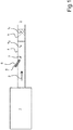
- the internal combustion engine 1 produces exhaust gases 2 that are discharged from the internal combustion engine 1 to an outside environment 3 via an exhaust line 4.
- the exhaust gases 2 comprise, in particular, nitrogen oxides NO x (x being equal to 1 or 2) that it is desirable not to reject to the external environment 3.
- the exhaust line 4 houses a reduction catalyst 5 to the inside which the nitrogen oxides are reduced prior to their discharge to the external environment 3.
- the exhaust line 4 is provided with a injection device 6 of a reducing agent 7 inside the exhaust line 4. The injection device 6 is placed on the exhaust line 4 between the internal combustion engine 1 and the reduction catalyst 5.
- the reduction catalyst 5 is particularly useful and effective, when the exhaust gas 2 at the reduction catalyst 5 has a catalyst temperature T c which is between 150 ° C and 175 ° C.
- the injector preferably opens into a zone called injection section of the injection line which can be equipped with means intended to facilitate the mixing of urea decomposed with ammonia and / or being decomposed into ammonia in the stream. exhaust gas before the assembly enters the reduction catalyst. For example, one can choose an injection section as described in the patent WO2010 / 146285 .
- the exhaust line 4 is in particular an exhaust line such as that described in the document FR 2,947,003 which comprises two upstream and downstream exhaust gas processing monoliths 2 flowing in the exhaust line 4, the two upstream and downstream monoliths being placed in series in the exhaust line 4, an injection section disposed between a upstream face defined by the upstream monolith and a downstream face defined by the downstream monolith and comprising a circulation channel of an exhaust gas flow extending from the upstream face to the downstream face, the channel having a central line having a determined length between the upstream and downstream faces, the injection section comprising the injection device 6 of the reducing agent 7 mounted on the injection section and able to inject the reducing agent 7 into the injection section .
- an exhaust line such as that described in the document FR 2,947,003 which comprises two upstream and downstream exhaust gas processing monoliths 2 flowing in the exhaust line 4, the two upstream and downstream monoliths being placed in series in the exhaust line 4, an injection section disposed between a upstream face defined by the upstream monolith and a downstream face defined
- the injection section comprises at least a first cup disposed inside the circulation channel in the path of the exhaust gas flow so that the average path of the exhaust gas stream is at least greater than at least 20% with respect to the determined length.
- the injection section comprises a cup disposed inside the circulation channel in the path of the exhaust gas flow. This cup is called weir.
- the spillway has a bottom spiraling around the central line of the injection section and a large opening at the end of the spiral furthest away from the upstream face. The opening is inclined both with respect to the central line and with respect to a plane perpendicular to the central line.
- the diameter of the cup is equal to the inside diameter of the exhaust gas circulation channel. It extends throughout the right section of the circulation channel. The peripheral edge of the cup bears against the inner surface of the circulation channel.
- the spiral shape of the weir initiates the rotating movement of the exhaust gases 2, the only escape route being downstream. The exhaust gases 2 perform about one complete revolution.
- the exhaust line 4 is still such that the exhaust line 4 described in the document FR 2,947,004 which includes a hot duct and a duct exhaust gas circulation cold 2, a mechanical decoupling element connecting the downstream end of the hot conduit to the upstream end of the cold conduit, the reduction catalyst 5, and the injection device 6 for injecting the reducing agent 7 or producing the reducing agent 7 in the exhaust line 4 upstream reduction catalyst 5, the exhaust line 2 being characterized in that the injection device 6 and the reduction catalyst 5 are intercalated in the hot duct, upstream of the mechanical decoupling element.
- the motor vehicle is likely to move in a driving mode for which, the internal combustion engine 1 is relatively cold, at the start of the latter in particular.
- the exhaust line 4 is capable of housing an oxidation catalyst interposed between the internal combustion engine 1 and the reduction catalyst 5, which tends to cool the exhaust gases 2, prior to their arrival at the level of the engine.
- the exhaust gas 2 has a gas temperature T g which is less than 150 ° C. that is, below a catalyst temperature T c of operation of the injection device 6 coupled to the reduction catalyst 5.
- the present invention proposes to equip the injection device 6 with a heating means 8,8 'to increase the temperature of the reducing agent 7 when it is delivered inside the exhaust line 4. the frequent case where the reducing agent 7 comprises urea and water, such heating can initiate a decomposition of the reducing agent 7 from a water evaporation and a start of thermolysis of urea.
- the heating means 8,8 comprises a first heating means 8 which equips a delivery end 20 of the injection device 6, the latter being licked by the exhaust gases 2 during their circulation inside the the exhaust line 4.
- the delivery end 20 is housed inside the exhaust line 4, so that the reducing agent 7 is heated after a release of the latter to the 2.
- the first heating means 8 is for example organized in a heating cone which envelops the delivery end 20 and which is provided with at least one perforation 21 for the passage of the gases. exhaust 2 to his through.
- the heating cone is indifferently a heating cone by Joule effect or by induction.
- the heating means 8,8 ' comprises a second heating means 8' which equips a delivery member 9 with the reducing agent 7.
- delivery 9 preferably houses a delivery ramp 22 of the reducing agent 7 as described above to increase a distance traveled by any drop of reducing agent 7 between the reserve 10 and the injector 11.
- the delivery ramp 22 is preferably arranged in a helix portion.
- the delivery ramp 22 comprises a helical turn.
- the delivery ramp 22 comprises a plurality of helical turns.
- the delivery member 9 is arranged between a reserve 10 of reducing agent 7 and an injector 11 of reducing agent 7.
- the delivery member 9 comprises at least one delivery cone of the reducing agent 7.
- the second means 8 ' is indifferently constituted of at least one heating resistor which is contiguous to the delivery member 9, a heating sleeve which envelops the delivery member 9 or an induction heating coil or the like . From a heating of the reducing agent 7, it is possible to reduce the nitrogen oxides at the start of the internal combustion engine 1.
- the heating means 8, 8 ' is capable of delivering a heating power which is between 100 W and 2000 W, preferably of the order of 1200 W to within +/- 10%. These arrangements offer the best possible compromise between an electric power consumed and a decomposition of the reducing agent 7 to make it effective to reduce the nitrogen oxides inside the reduction catalyst 5.
- the heating means 8, 8 ' is activated according to a catalyst temperature T c of the reduction catalyst 5. More particularly, the injection of reducing agent 7 inside the exhaust line is placed under the control of the catalyst temperature T c reduction catalyst 5, in the sense that the injection is carried out as soon as the catalyst temperature T c of the reduction catalyst 5 is greater than 100 ° C.
Landscapes
- Chemical & Material Sciences (AREA)
- Engineering & Computer Science (AREA)
- Chemical Kinetics & Catalysis (AREA)
- Health & Medical Sciences (AREA)
- Toxicology (AREA)
- Combustion & Propulsion (AREA)
- Mechanical Engineering (AREA)
- General Engineering & Computer Science (AREA)
- Exhaust Gas After Treatment (AREA)
Description
L'invention porte sur un dispositif d'injection d'un agent réducteur à l'intérieur d'une ligne d'échappement équipant une ligne d'échappement d'un moteur à combustion interne dont est pourvu un véhicule automobile, le dispositif d'injection comprenant une réserve d'agent réducteur et un injecteur de l'agent réducteur à l'intérieur de la ligne d'échappement entre lesquels est interposé un organe de délivrance.The invention relates to a device for injecting a reducing agent into an exhaust line fitted to an exhaust line of an internal combustion engine which is provided with a motor vehicle, the device for injection comprising a reserve of reducing agent and an injector of the reducing agent inside the exhaust line between which is interposed a delivery member.
Le document
Un problème général posé par un tel dispositif réside dans le fait qu'il mérite d'être amélioré pour optimiser une réduction d'oxydes d'azote véhiculés par des gaz d'échappement circulant à l'intérieur de la ligne d'échappement. Plus particulièrement, il est souhaitable de disposer d'un dispositif d'injection qui offre un bon compromis entre une réduction optimisée des oxydes d'azote véhiculés par les gaz d'échappement et une consommation énergétique d'un tel dispositif d'injection pour décomposer l'agent réducteur.A general problem posed by such a device lies in the fact that it deserves to be improved to optimize a reduction of nitrogen oxides carried by exhaust gases circulating inside the exhaust line. More particularly, it is desirable to have an injection device that offers a good compromise between an optimized reduction of the nitrogen oxides conveyed by the exhaust gases and an energy consumption of such an injection device to decompose the reducing agent.
Le but de la présente invention est de proposer un dispositif d'injection qui répond aux inconvénients susvisés.The object of the present invention is to provide an injection device that meets the aforementioned drawbacks.
Un dispositif de la présente invention est un dispositif d'injection d'un agent réducteur à l'intérieur d'une ligne d'échappement équipant un moteur à combustion interne dont est pourvu un véhicule automobile. Le dispositif d'injection comprend une réserve d'agent réducteur et un injecteur de l'agent réducteur à l'intérieur de la ligne d'échappement. Un organe de délivrance est interposé entre la réserve et l'injecteur. L'organe de délivrance comprend au moins une rampe de délivrance de l'agent réducteur.A device of the present invention is a device for injecting a reducing agent into an exhaust line fitted to an internal combustion engine which is provided with a motor vehicle. The injection device comprises a supply of reducing agent and a reducing agent injector inside the line exhaust. A delivery member is interposed between the supply and the injector. The delivery member comprises at least one delivery line of the reducing agent.
L'invention a donc pour objet un dispositif d'injection d'un agent réducteur à l'intérieur d'une ligne d'échappement équipant un moteur à combustion interne dont est pourvu un véhicule automobile, le dispositif d'injection comprenant une réserve d'agent réducteur et un injecteur de l'agent réducteur qui comporte une extrémité de délivrance destinée à être logée à l'intérieur de la ligne d'échappement, et un organe de délivrance étant interposé entre la réserve et l'injecteur, l'organe de délivrance comprenant au moins une rampe de délivrance de l'agent réducteur, tel que le dispositif d'injection est pourvu d'au moins un premier moyen de chauffage de l'agent réducteur apte à délivrer une puissance de chauffe sous forme d'un cône de chauffage qui enveloppe l'extrémité de délivrance destinée à être logée à l'intérieur de la ligne d'échappement, ledit cône de chauffage étant pourvu d'au moins une perforation pour le passage des gaz d'échappement à son traversThe subject of the invention is therefore a device for injecting a reducing agent into an exhaust line fitted to an internal combustion engine provided with a motor vehicle, the injection device comprising a reserve of reducing agent and an injector of the reducing agent which comprises a delivery end intended to be housed inside the exhaust line, and a delivery member being interposed between the reserve and the injector, the organ delivery device comprising at least one delivery line of the reducing agent, such that the injection device is provided with at least a first means for heating the reducing agent capable of delivering a heating power in the form of a heating cone which envelopes the delivery end intended to be housed inside the exhaust line, said heating cone being provided with at least one perforation for the passage of the exhaust gases through it
Selon la présente invention, le dispositif d'injection est pourvu d'au moins un moyen de chauffage de l'agent réducteur.According to the present invention, the injection device is provided with at least one means for heating the reducing agent.
Un premier moyen de chauffage équipe avantageusement une extrémité de délivrance que comporte l'injecteur.A first heating means advantageously equips a delivery end that includes the injector.
Un deuxième moyen de chauffage équipe avantageusement l'organe de délivrance.A second heating means advantageously equips the delivery member.
Le moyen de chauffage est avantageusement apte à délivrer une puissance de chauffe comprise entre 100 W et 2 000 W.The heating means is advantageously capable of delivering a heating power of between 100 W and 2000 W.
Le moyen de chauffage est préférentiellement apte à délivrer une puissance de l'ordre de 1 200 W à +/- 10% près.The heating means is preferably capable of delivering a power on the order of 1200 W to +/- 10%.
Le moyen de chauffage comprend par exemple au moins une résistance chauffante par effet Joule.The heating means comprises for example at least one heating resistor by Joule effect.
Le moyen de chauffage comprend par exemple au moins une bobine de chauffage par induction.The heating means comprises for example at least one induction heating coil.
Une ligne d'échappement de la présente invention est principalement reconnaissable en ce que la ligne d'échappement est équipée d'un tel dispositif d'injection.An exhaust line of the present invention is mainly recognizable in that the exhaust line is equipped with such an injection device.
Un véhicule automobile de la présente invention est principalement reconnaissable en ce que le véhicule automobile comprend un moteur à combustion interne pourvu d'une telle ligne d'échappement.A motor vehicle of the present invention is mainly recognizable in that the motor vehicle comprises an internal combustion engine provided with such an exhaust line.
Un procédé de mise en oeuvre du moyen de chauffage constitutif d'un tel dispositif d'injection est principalement caractérisé en ce que la mise en oeuvre du moyen de chauffage est placé sous la dépendance d'une température d'un catalyseur de réduction logé à l'intérieur de la ligne d'échappement.A method of operating the heating means constituting such an injection device is mainly characterized in that the implementation of the heating means is placed under the control of a temperature of a reduction catalyst housed at inside the exhaust line.
D'autres caractéristiques et avantages de la présente invention apparaîtront à la lecture de la description qui va en être faite d'exemples de réalisation, en relation avec les figures des planches annexées, dans lesquelles :
- La
figure 1 est une vue schématique d'une ligne d'échappement de la présente invention. - La
figure 2 est une vue schématique d'un injecteur d'un agent réducteur à l'intérieur de la ligne d'échappement, telle celle illustrée sur lafigure 1 , dont est pourvu un moteur à combustion interne équipant un véhicule automobile.
- The
figure 1 is a schematic view of an exhaust line of the present invention. - The
figure 2 is a schematic view of an injector of a reducing agent inside the exhaust line, such as that illustrated in FIG.figure 1 , which is provided with an internal combustion engine fitted to a motor vehicle.
Sur la
La ligne d'échappement 4 est notamment une ligne d'échappement telle que celle décrite dans le document
La ligne d'échappement 4 est notamment encore telle que la ligne d'échappement 4 décrite dans le document
Le véhicule automobile est susceptible de se déplacer dans un mode de roulage pour lequel, le moteur à combustion interne 1 est relativement froid, au démarrage de ce dernier notamment. De plus, la ligne d'échappement 4 est susceptible de loger un catalyseur d'oxydation interposé entre le moteur à combustion interne 1 et le catalyseur de réduction 5 ce qui tend à refroidir les gaz d'échappement 2, préalablement à leur arrivée au niveau du catalyseur de réduction 5. Dans l'un et/ou l'autre de ces cas, au niveau du catalyseur de réduction 5, les gaz d'échappement 2 présentent une température de gaz Tg qui est inférieure à 150°C, c'est-à-dire en dessous d'une température de catalyseur Tc utile de fonctionnement du dispositif d'injection 6 couplé au catalyseur de réduction 5.The motor vehicle is likely to move in a driving mode for which, the
La présente invention propose d'équiper le dispositif d'injection 6 d'un moyen de chauffage 8,8' pour augmenter la température de l'agent réducteur 7 lors de sa délivrance à l'intérieur de la ligne d'échappement 4. Dans le cas fréquent où l'agent réducteur 7 comprend de l'urée et de l'eau, un tel chauffage permet d'initier une décomposition de l'agent réducteur 7 à partir d'une évaporation d'eau et d'un début de thermolyse de l'urée.The present invention proposes to equip the
Sur la
Sur la
Le moyen de chauffage 8,8' est à même de délivrer une puissance de chauffe qui est comprise entre 100 W et 2 000 W, préférentiellement de l'ordre de 1 200 W à +/- 10% près. Ces dispositions offrent le meilleur compromis possible entre une puissance électrique consommée et une décomposition de l'agent réducteur 7 pour rendre ce dernier efficace afin de réduire les oxydes d'azote à l'intérieur du catalyseur de réduction 5. Le moyen de chauffage 8,8' est activé selon une température de catalyseur Tc du catalyseur de réduction 5. Plus particulièrement, l'injection d'agent réducteur 7 à l'intérieur de la ligne d'échappement est placée sous la dépendance de la température de catalyseur Tc du catalyseur de réduction 5, dans le sens où l'injection est réalisée dès que la température de catalyseur Tc du catalyseur de réduction 5 est supérieure à 100°C.The heating means 8, 8 'is capable of delivering a heating power which is between 100 W and 2000 W, preferably of the order of 1200 W to within +/- 10%. These arrangements offer the best possible compromise between an electric power consumed and a decomposition of the reducing
L'ensemble de ces dispositions est tel que sous une contrainte de volume disponible pour le dispositif d'injection 6, le meilleur compromis est obtenu pour éviter un encrassement du catalyseur de réduction 5 à partir d'une augmentation de la décomposition de l'agent réducteur rendue possible par l'intermédiaire du moyen de chauffage 8,8'. Ces dispositions permettent notamment une réduction des oxydes d'azote NOx à faible température du catalyseur de réduction 5 et permettent ainsi une dépollution des gaz d'échappement 2 par exemple en roulage urbain et au démarrage.All of these provisions are such that under a volume constraint available for the
Claims (9)
- A device (6) for injecting a reducing agent (7) into an exhaust line (4) equipping an internal combustion engine (1) with which a motor vehicle (1) is provided, the injection device (6) including a reserve (10) of reducing agent (7) and an injector (11) of the reducing agent (7) which comprises a delivery end (20) intended to be housed inside the exhaust line (4), and a delivery element (9) being interposed between the reserve (10) and the injector (11), the delivery element (9) including at least one delivery ramp (22) of the reducing agent (7), characterized in that the injection device (6) is provided with at least a first means (8) for heating the reducing agent (7) able to deliver a heating power in the form of a heating cone which envelops the delivery end (20) intended to be housed inside the exhaust line, said heating cone being provided with at least one perforation (21) for the passage of the exhaust gases through it.
- The device according to the preceding claim characterized in that a second heating means (8') equips the delivery element (9), in particular by being attached thereto or by being in the form of a heating sleeve enveloping the delivery element or in the form of an induction heating coil.
- The device according to any one of the preceding claims, characterized in that the first heating means (8,8') is able to deliver a heating power comprised between 100 W and 2 000 W.
- The device according to the preceding claim, characterized in that the heating means (8,8') is able to deliver a power in the order of 1 200 W +/- 10%.
- The device according to any one of the preceding claims, characterized in that the heating means (8,8') includes at least one Joule effect heating resistor.
- The device according to any one of Claims 1 to 4, characterized in that the heating means (8,8') includes at least one induction heating coil.
- An exhaust line (4) equipped with an injection device (6) according to any one of the preceding claims.
- A motor vehicle including an internal combustion engine (1) provided with an exhaust line (4) according to the preceding claim.
- A method for implementing a heating means (8,8'), being a constituent of the injection device (6) according to any one of Claims 1 to 6, characterized in that the implementation of the heating means (8,8') is placed under the dependence of a temperature (Tc) of a reduction catalyst (5) housed inside the exhaust line (4).
Applications Claiming Priority (1)
| Application Number | Priority Date | Filing Date | Title |
|---|---|---|---|
| FR1352168A FR3003297B1 (en) | 2013-03-12 | 2013-03-12 | DEVICE FOR INJECTING A REDUCING AGENT INSIDE AN EXHAUST LINE |
Publications (2)
| Publication Number | Publication Date |
|---|---|
| EP2778360A1 EP2778360A1 (en) | 2014-09-17 |
| EP2778360B1 true EP2778360B1 (en) | 2017-05-03 |
Family
ID=48225052
Family Applications (1)
| Application Number | Title | Priority Date | Filing Date |
|---|---|---|---|
| EP14158590.1A Active EP2778360B1 (en) | 2013-03-12 | 2014-03-10 | Device for injecting a reducing agent into an exhaust line |
Country Status (2)
| Country | Link |
|---|---|
| EP (1) | EP2778360B1 (en) |
| FR (1) | FR3003297B1 (en) |
Families Citing this family (1)
| Publication number | Priority date | Publication date | Assignee | Title |
|---|---|---|---|---|
| EP3150813A1 (en) * | 2015-09-30 | 2017-04-05 | Plastic Omnium Advanced Innovation and Research | Feed line system for a vehicle system |
Family Cites Families (7)
| Publication number | Priority date | Publication date | Assignee | Title |
|---|---|---|---|---|
| US6722123B2 (en) * | 2001-10-17 | 2004-04-20 | Fleetguard, Inc. | Exhaust aftertreatment device, including chemical mixing and acoustic effects |
| EP1785606B1 (en) * | 2004-09-02 | 2014-06-11 | Nissan Diesel Motor Co., Ltd. | Exhaust gas purifier |
| DE102008002286A1 (en) * | 2008-06-09 | 2009-12-10 | Robert Bosch Gmbh | Exhaust after-treatment device for an internal combustion engine with an SCR catalytic converter and method for operating an internal combustion engine |
| FR2947003B1 (en) | 2009-06-19 | 2015-04-10 | Faurecia Sys Echappement | EXHAUST LINE WITH INJECTION SYSTEM |
| FR2947004B1 (en) | 2009-06-22 | 2015-12-11 | Faurecia Sys Echappement | EXHAUST LINE WITH DEVICE FOR TREATING NITROGEN OXIDES. |
| US8240137B2 (en) | 2009-10-27 | 2012-08-14 | Cummins Filtration Ip, Inc. | Reductant injection and decomposition system |
| DE102010055520B4 (en) * | 2010-12-22 | 2023-10-05 | Voss Automotive Gmbh | Assembled media line and use in an SCR catalytic converter system |
-
2013
- 2013-03-12 FR FR1352168A patent/FR3003297B1/en active Active
-
2014
- 2014-03-10 EP EP14158590.1A patent/EP2778360B1/en active Active
Also Published As
| Publication number | Publication date |
|---|---|
| EP2778360A1 (en) | 2014-09-17 |
| FR3003297A1 (en) | 2014-09-19 |
| FR3003297B1 (en) | 2015-03-27 |
Similar Documents
| Publication | Publication Date | Title |
|---|---|---|
| FR2915344A1 (en) | FLUID HEATING DEVICE AND EXHAUST PURIFYING APPARATUS EQUIPPED WITH SUCH A DEVICE. | |
| FR3014136A1 (en) | REDUCER INJECTION DEVICE AND CORRESPONDING EXHAUST LINE | |
| WO2012052672A1 (en) | Motor vehicle exhaust line | |
| WO2009103869A2 (en) | Heating pipe for conveying fluid | |
| FR2926595A1 (en) | EXHAUST GAS PURIFYING DEVICE OF INTERNAL COMBUSTION ENGINE. | |
| FR2905161A1 (en) | CONNECTION WITH INTEGRATED HEATING ELEMENT. | |
| WO2012052690A1 (en) | Device for introducing a liquid additive into a combustion engine exhaust line | |
| FR2953254A1 (en) | Bonnet for air inlet of jet engine in aircraft, has helicoidal channel formed at interior of tubular mixture at which injector is suited to inject part of hot air flow by upstream end of tubular mixture | |
| EP2778360B1 (en) | Device for injecting a reducing agent into an exhaust line | |
| FR2915185A1 (en) | Urea tank module for motor vehicle, has conduit whose one end is raised at proximity of wall and another end is connected to aspiration units, and pipe connected to compartment for allowing recovery of urea in tank | |
| WO2011138514A2 (en) | Fluid reservoir having a heating reserve bowl | |
| FR2902470A1 (en) | Exhaust gas regulation valve for engine of motor vehicle, has electrical motor for controlling valve, crown placed at junction between inlet channel and bent part of body, and annular electrical resistor for heating crown by Joule effect | |
| FR3081978A1 (en) | HEAT TREATMENT DEVICE WITH REFRACTORY COVER | |
| EP1672194B1 (en) | Method of regeneration of a particulate filter with an catalytic combustion apparatus and filter installation using the method | |
| FR3043730A3 (en) | EXHAUST SYSTEM OF AN INTERNAL COMBUSTION ENGINE WITH COOLING RECIRCULATED COMBUSTION GASES. | |
| EP3977013A1 (en) | Pre-vaporizing pipe, combustion assembly provided therewith and turbomachine provided therewith | |
| FR2906575A1 (en) | Injector cooling arrangement for e.g. cylinder head of heat engine, has internal and external rings interposed between injector nozzle and housing wall to allow transmission of heat accumulated in nozzle to element of heat engine | |
| FR3022582A1 (en) | CATALYTIC SELECTIVE REDUCTION SYSTEM HAVING INSERT HEATER ON ITS INJECTOR | |
| FR3118098A1 (en) | Device for injecting a fluid into an exhaust pipe and associated exhaust system | |
| FR3079264A1 (en) | HEAT EXHAUST GAS PURIFYING DEVICE AND PURIFYING DEVICE COMPRISING SUCH A PURIFYING BODY | |
| EP1914400B1 (en) | Exhaust line with a catalyst and a temperature sensor | |
| WO2009044084A1 (en) | System for introducing a vaporized fuel inside an exhaust element | |
| WO2014147305A1 (en) | Device for treating exhaust gases by catalysis | |
| FR2829183A1 (en) | Depollution device in vehicle exhaust comprises inlet deflector which controls area of device in use to increase as temperature of exhaust gases increases | |
| FR3103858A1 (en) | Exhaust gas purification device, exhaust line and associated vehicle |
Legal Events
| Date | Code | Title | Description |
|---|---|---|---|
| 17P | Request for examination filed |
Effective date: 20140310 |
|
| AK | Designated contracting states |
Kind code of ref document: A1 Designated state(s): AL AT BE BG CH CY CZ DE DK EE ES FI FR GB GR HR HU IE IS IT LI LT LU LV MC MK MT NL NO PL PT RO RS SE SI SK SM TR |
|
| AX | Request for extension of the european patent |
Extension state: BA ME |
|
| PUAI | Public reference made under article 153(3) epc to a published international application that has entered the european phase |
Free format text: ORIGINAL CODE: 0009012 |
|
| R17P | Request for examination filed (corrected) |
Effective date: 20150204 |
|
| RBV | Designated contracting states (corrected) |
Designated state(s): AL AT BE BG CH CY CZ DE DK EE ES FI FR GB GR HR HU IE IS IT LI LT LU LV MC MK MT NL NO PL PT RO RS SE SI SK SM TR |
|
| 17Q | First examination report despatched |
Effective date: 20160229 |
|
| GRAP | Despatch of communication of intention to grant a patent |
Free format text: ORIGINAL CODE: EPIDOSNIGR1 |
|
| INTG | Intention to grant announced |
Effective date: 20161111 |
|
| GRAS | Grant fee paid |
Free format text: ORIGINAL CODE: EPIDOSNIGR3 |
|
| GRAA | (expected) grant |
Free format text: ORIGINAL CODE: 0009210 |
|
| AK | Designated contracting states |
Kind code of ref document: B1 Designated state(s): AL AT BE BG CH CY CZ DE DK EE ES FI FR GB GR HR HU IE IS IT LI LT LU LV MC MK MT NL NO PL PT RO RS SE SI SK SM TR |
|
| REG | Reference to a national code |
Ref country code: GB Ref legal event code: FG4D Free format text: NOT ENGLISH |
|
| REG | Reference to a national code |
Ref country code: AT Ref legal event code: REF Ref document number: 890253 Country of ref document: AT Kind code of ref document: T Effective date: 20170515 Ref country code: CH Ref legal event code: EP |
|
| REG | Reference to a national code |
Ref country code: IE Ref legal event code: FG4D Free format text: LANGUAGE OF EP DOCUMENT: FRENCH |
|
| REG | Reference to a national code |
Ref country code: DE Ref legal event code: R096 Ref document number: 602014009184 Country of ref document: DE |
|
| REG | Reference to a national code |
Ref country code: DE Ref legal event code: R084 Ref document number: 602014009184 Country of ref document: DE |
|
| RAP2 | Party data changed (patent owner data changed or rights of a patent transferred) |
Owner name: PSA AUTOMOBILES SA |
|
| REG | Reference to a national code |
Ref country code: NL Ref legal event code: MP Effective date: 20170503 |
|
| REG | Reference to a national code |
Ref country code: AT Ref legal event code: MK05 Ref document number: 890253 Country of ref document: AT Kind code of ref document: T Effective date: 20170503 |
|
| REG | Reference to a national code |
Ref country code: LT Ref legal event code: MG4D |
|
| PG25 | Lapsed in a contracting state [announced via postgrant information from national office to epo] |
Ref country code: FI Free format text: LAPSE BECAUSE OF FAILURE TO SUBMIT A TRANSLATION OF THE DESCRIPTION OR TO PAY THE FEE WITHIN THE PRESCRIBED TIME-LIMIT Effective date: 20170503 Ref country code: ES Free format text: LAPSE BECAUSE OF FAILURE TO SUBMIT A TRANSLATION OF THE DESCRIPTION OR TO PAY THE FEE WITHIN THE PRESCRIBED TIME-LIMIT Effective date: 20170503 Ref country code: LT Free format text: LAPSE BECAUSE OF FAILURE TO SUBMIT A TRANSLATION OF THE DESCRIPTION OR TO PAY THE FEE WITHIN THE PRESCRIBED TIME-LIMIT Effective date: 20170503 Ref country code: GR Free format text: LAPSE BECAUSE OF FAILURE TO SUBMIT A TRANSLATION OF THE DESCRIPTION OR TO PAY THE FEE WITHIN THE PRESCRIBED TIME-LIMIT Effective date: 20170804 Ref country code: NO Free format text: LAPSE BECAUSE OF FAILURE TO SUBMIT A TRANSLATION OF THE DESCRIPTION OR TO PAY THE FEE WITHIN THE PRESCRIBED TIME-LIMIT Effective date: 20170803 Ref country code: AT Free format text: LAPSE BECAUSE OF FAILURE TO SUBMIT A TRANSLATION OF THE DESCRIPTION OR TO PAY THE FEE WITHIN THE PRESCRIBED TIME-LIMIT Effective date: 20170503 Ref country code: HR Free format text: LAPSE BECAUSE OF FAILURE TO SUBMIT A TRANSLATION OF THE DESCRIPTION OR TO PAY THE FEE WITHIN THE PRESCRIBED TIME-LIMIT Effective date: 20170503 |
|
| PG25 | Lapsed in a contracting state [announced via postgrant information from national office to epo] |
Ref country code: BG Free format text: LAPSE BECAUSE OF FAILURE TO SUBMIT A TRANSLATION OF THE DESCRIPTION OR TO PAY THE FEE WITHIN THE PRESCRIBED TIME-LIMIT Effective date: 20170803 Ref country code: PL Free format text: LAPSE BECAUSE OF FAILURE TO SUBMIT A TRANSLATION OF THE DESCRIPTION OR TO PAY THE FEE WITHIN THE PRESCRIBED TIME-LIMIT Effective date: 20170503 Ref country code: RS Free format text: LAPSE BECAUSE OF FAILURE TO SUBMIT A TRANSLATION OF THE DESCRIPTION OR TO PAY THE FEE WITHIN THE PRESCRIBED TIME-LIMIT Effective date: 20170503 Ref country code: LV Free format text: LAPSE BECAUSE OF FAILURE TO SUBMIT A TRANSLATION OF THE DESCRIPTION OR TO PAY THE FEE WITHIN THE PRESCRIBED TIME-LIMIT Effective date: 20170503 Ref country code: IS Free format text: LAPSE BECAUSE OF FAILURE TO SUBMIT A TRANSLATION OF THE DESCRIPTION OR TO PAY THE FEE WITHIN THE PRESCRIBED TIME-LIMIT Effective date: 20170903 Ref country code: SE Free format text: LAPSE BECAUSE OF FAILURE TO SUBMIT A TRANSLATION OF THE DESCRIPTION OR TO PAY THE FEE WITHIN THE PRESCRIBED TIME-LIMIT Effective date: 20170503 Ref country code: NL Free format text: LAPSE BECAUSE OF FAILURE TO SUBMIT A TRANSLATION OF THE DESCRIPTION OR TO PAY THE FEE WITHIN THE PRESCRIBED TIME-LIMIT Effective date: 20170503 |
|
| PG25 | Lapsed in a contracting state [announced via postgrant information from national office to epo] |
Ref country code: SK Free format text: LAPSE BECAUSE OF FAILURE TO SUBMIT A TRANSLATION OF THE DESCRIPTION OR TO PAY THE FEE WITHIN THE PRESCRIBED TIME-LIMIT Effective date: 20170503 Ref country code: EE Free format text: LAPSE BECAUSE OF FAILURE TO SUBMIT A TRANSLATION OF THE DESCRIPTION OR TO PAY THE FEE WITHIN THE PRESCRIBED TIME-LIMIT Effective date: 20170503 Ref country code: CZ Free format text: LAPSE BECAUSE OF FAILURE TO SUBMIT A TRANSLATION OF THE DESCRIPTION OR TO PAY THE FEE WITHIN THE PRESCRIBED TIME-LIMIT Effective date: 20170503 Ref country code: DK Free format text: LAPSE BECAUSE OF FAILURE TO SUBMIT A TRANSLATION OF THE DESCRIPTION OR TO PAY THE FEE WITHIN THE PRESCRIBED TIME-LIMIT Effective date: 20170503 Ref country code: RO Free format text: LAPSE BECAUSE OF FAILURE TO SUBMIT A TRANSLATION OF THE DESCRIPTION OR TO PAY THE FEE WITHIN THE PRESCRIBED TIME-LIMIT Effective date: 20170503 |
|
| REG | Reference to a national code |
Ref country code: DE Ref legal event code: R097 Ref document number: 602014009184 Country of ref document: DE |
|
| REG | Reference to a national code |
Ref country code: FR Ref legal event code: PLFP Year of fee payment: 5 |
|
| PG25 | Lapsed in a contracting state [announced via postgrant information from national office to epo] |
Ref country code: IT Free format text: LAPSE BECAUSE OF FAILURE TO SUBMIT A TRANSLATION OF THE DESCRIPTION OR TO PAY THE FEE WITHIN THE PRESCRIBED TIME-LIMIT Effective date: 20170503 Ref country code: SM Free format text: LAPSE BECAUSE OF FAILURE TO SUBMIT A TRANSLATION OF THE DESCRIPTION OR TO PAY THE FEE WITHIN THE PRESCRIBED TIME-LIMIT Effective date: 20170503 |
|
| PLBE | No opposition filed within time limit |
Free format text: ORIGINAL CODE: 0009261 |
|
| STAA | Information on the status of an ep patent application or granted ep patent |
Free format text: STATUS: NO OPPOSITION FILED WITHIN TIME LIMIT |
|
| 26N | No opposition filed |
Effective date: 20180206 |
|
| PG25 | Lapsed in a contracting state [announced via postgrant information from national office to epo] |
Ref country code: SI Free format text: LAPSE BECAUSE OF FAILURE TO SUBMIT A TRANSLATION OF THE DESCRIPTION OR TO PAY THE FEE WITHIN THE PRESCRIBED TIME-LIMIT Effective date: 20170503 |
|
| REG | Reference to a national code |
Ref country code: FR Ref legal event code: CA Effective date: 20180312 Ref country code: FR Ref legal event code: CD Owner name: PEUGEOT CITROEN AUTOMOBILES SA, FR Effective date: 20180312 |
|
| PG25 | Lapsed in a contracting state [announced via postgrant information from national office to epo] |
Ref country code: MT Free format text: LAPSE BECAUSE OF FAILURE TO SUBMIT A TRANSLATION OF THE DESCRIPTION OR TO PAY THE FEE WITHIN THE PRESCRIBED TIME-LIMIT Effective date: 20170503 |
|
| REG | Reference to a national code |
Ref country code: CH Ref legal event code: PL |
|
| GBPC | Gb: european patent ceased through non-payment of renewal fee |
Effective date: 20180310 |
|
| PG25 | Lapsed in a contracting state [announced via postgrant information from national office to epo] |
Ref country code: MC Free format text: LAPSE BECAUSE OF FAILURE TO SUBMIT A TRANSLATION OF THE DESCRIPTION OR TO PAY THE FEE WITHIN THE PRESCRIBED TIME-LIMIT Effective date: 20170503 |
|
| REG | Reference to a national code |
Ref country code: BE Ref legal event code: MM Effective date: 20180331 |
|
| REG | Reference to a national code |
Ref country code: IE Ref legal event code: MM4A |
|
| PG25 | Lapsed in a contracting state [announced via postgrant information from national office to epo] |
Ref country code: LU Free format text: LAPSE BECAUSE OF NON-PAYMENT OF DUE FEES Effective date: 20180310 |
|
| PG25 | Lapsed in a contracting state [announced via postgrant information from national office to epo] |
Ref country code: IE Free format text: LAPSE BECAUSE OF NON-PAYMENT OF DUE FEES Effective date: 20180310 |
|
| PG25 | Lapsed in a contracting state [announced via postgrant information from national office to epo] |
Ref country code: BE Free format text: LAPSE BECAUSE OF NON-PAYMENT OF DUE FEES Effective date: 20180331 Ref country code: GB Free format text: LAPSE BECAUSE OF NON-PAYMENT OF DUE FEES Effective date: 20180310 Ref country code: LI Free format text: LAPSE BECAUSE OF NON-PAYMENT OF DUE FEES Effective date: 20180331 Ref country code: CH Free format text: LAPSE BECAUSE OF NON-PAYMENT OF DUE FEES Effective date: 20180331 |
|
| PG25 | Lapsed in a contracting state [announced via postgrant information from national office to epo] |
Ref country code: TR Free format text: LAPSE BECAUSE OF FAILURE TO SUBMIT A TRANSLATION OF THE DESCRIPTION OR TO PAY THE FEE WITHIN THE PRESCRIBED TIME-LIMIT Effective date: 20170503 |
|
| PG25 | Lapsed in a contracting state [announced via postgrant information from national office to epo] |
Ref country code: PT Free format text: LAPSE BECAUSE OF FAILURE TO SUBMIT A TRANSLATION OF THE DESCRIPTION OR TO PAY THE FEE WITHIN THE PRESCRIBED TIME-LIMIT Effective date: 20170503 Ref country code: HU Free format text: LAPSE BECAUSE OF FAILURE TO SUBMIT A TRANSLATION OF THE DESCRIPTION OR TO PAY THE FEE WITHIN THE PRESCRIBED TIME-LIMIT; INVALID AB INITIO Effective date: 20140310 |
|
| PG25 | Lapsed in a contracting state [announced via postgrant information from national office to epo] |
Ref country code: MK Free format text: LAPSE BECAUSE OF NON-PAYMENT OF DUE FEES Effective date: 20170503 Ref country code: CY Free format text: LAPSE BECAUSE OF FAILURE TO SUBMIT A TRANSLATION OF THE DESCRIPTION OR TO PAY THE FEE WITHIN THE PRESCRIBED TIME-LIMIT Effective date: 20170503 |
|
| PG25 | Lapsed in a contracting state [announced via postgrant information from national office to epo] |
Ref country code: AL Free format text: LAPSE BECAUSE OF FAILURE TO SUBMIT A TRANSLATION OF THE DESCRIPTION OR TO PAY THE FEE WITHIN THE PRESCRIBED TIME-LIMIT Effective date: 20170503 |
|
| PGFP | Annual fee paid to national office [announced via postgrant information from national office to epo] |
Ref country code: FR Payment date: 20230222 Year of fee payment: 10 |
|
| PGFP | Annual fee paid to national office [announced via postgrant information from national office to epo] |
Ref country code: DE Payment date: 20230221 Year of fee payment: 10 |
|
| PGFP | Annual fee paid to national office [announced via postgrant information from national office to epo] |
Ref country code: DE Payment date: 20240220 Year of fee payment: 11 |