EP2777831A1 - Procédé de nettoyage pour un mélangeur de produits en vrac et mélangeur de produits en vrac doté d'un récipient de mélange à nettoyer - Google Patents
Procédé de nettoyage pour un mélangeur de produits en vrac et mélangeur de produits en vrac doté d'un récipient de mélange à nettoyer Download PDFInfo
- Publication number
- EP2777831A1 EP2777831A1 EP14000140.5A EP14000140A EP2777831A1 EP 2777831 A1 EP2777831 A1 EP 2777831A1 EP 14000140 A EP14000140 A EP 14000140A EP 2777831 A1 EP2777831 A1 EP 2777831A1
- Authority
- EP
- European Patent Office
- Prior art keywords
- mixing container
- compressed air
- bulk material
- wall
- outlet opening
- Prior art date
- Legal status (The legal status is an assumption and is not a legal conclusion. Google has not performed a legal analysis and makes no representation as to the accuracy of the status listed.)
- Granted
Links
- 239000013590 bulk material Substances 0.000 title claims abstract description 99
- 238000000034 method Methods 0.000 title claims abstract description 23
- 238000004140 cleaning Methods 0.000 title claims description 28
- 239000000463 material Substances 0.000 claims abstract description 7
- 239000000203 mixture Substances 0.000 claims description 31
- 238000007664 blowing Methods 0.000 claims description 7
- 238000003780 insertion Methods 0.000 claims description 7
- 230000037431 insertion Effects 0.000 claims description 7
- 238000007599 discharging Methods 0.000 claims description 5
- 239000007787 solid Substances 0.000 claims description 4
- 125000006850 spacer group Chemical group 0.000 claims description 3
- 230000002093 peripheral effect Effects 0.000 claims description 2
- 239000004566 building material Substances 0.000 description 3
- 230000000694 effects Effects 0.000 description 3
- 238000011109 contamination Methods 0.000 description 2
- 230000002349 favourable effect Effects 0.000 description 2
- 238000002347 injection Methods 0.000 description 2
- 239000007924 injection Substances 0.000 description 2
- 239000000853 adhesive Substances 0.000 description 1
- 230000001070 adhesive effect Effects 0.000 description 1
- 230000015572 biosynthetic process Effects 0.000 description 1
- 230000003111 delayed effect Effects 0.000 description 1
- 238000009826 distribution Methods 0.000 description 1
- 230000005484 gravity Effects 0.000 description 1
- -1 however Substances 0.000 description 1
- 238000004519 manufacturing process Methods 0.000 description 1
- 230000035515 penetration Effects 0.000 description 1
- 238000002360 preparation method Methods 0.000 description 1
- 230000001681 protective effect Effects 0.000 description 1
- 239000002994 raw material Substances 0.000 description 1
- 238000007789 sealing Methods 0.000 description 1
- 239000013589 supplement Substances 0.000 description 1
Images


Classifications
-
- B—PERFORMING OPERATIONS; TRANSPORTING
- B01—PHYSICAL OR CHEMICAL PROCESSES OR APPARATUS IN GENERAL
- B01F—MIXING, e.g. DISSOLVING, EMULSIFYING OR DISPERSING
- B01F27/00—Mixers with rotary stirring devices in fixed receptacles; Kneaders
- B01F27/60—Mixers with rotary stirring devices in fixed receptacles; Kneaders with stirrers rotating about a horizontal or inclined axis
- B01F27/70—Mixers with rotary stirring devices in fixed receptacles; Kneaders with stirrers rotating about a horizontal or inclined axis with paddles, blades or arms
-
- B—PERFORMING OPERATIONS; TRANSPORTING
- B08—CLEANING
- B08B—CLEANING IN GENERAL; PREVENTION OF FOULING IN GENERAL
- B08B9/00—Cleaning hollow articles by methods or apparatus specially adapted thereto
- B08B9/08—Cleaning containers, e.g. tanks
- B08B9/0804—Cleaning containers having tubular shape, e.g. casks, barrels, drums
- B08B9/0813—Cleaning containers having tubular shape, e.g. casks, barrels, drums by the force of jets or sprays
-
- B—PERFORMING OPERATIONS; TRANSPORTING
- B01—PHYSICAL OR CHEMICAL PROCESSES OR APPARATUS IN GENERAL
- B01F—MIXING, e.g. DISSOLVING, EMULSIFYING OR DISPERSING
- B01F27/00—Mixers with rotary stirring devices in fixed receptacles; Kneaders
- B01F27/05—Stirrers
- B01F27/07—Stirrers characterised by their mounting on the shaft
- B01F27/071—Fixing of the stirrer to the shaft
-
- B—PERFORMING OPERATIONS; TRANSPORTING
- B01—PHYSICAL OR CHEMICAL PROCESSES OR APPARATUS IN GENERAL
- B01F—MIXING, e.g. DISSOLVING, EMULSIFYING OR DISPERSING
- B01F27/00—Mixers with rotary stirring devices in fixed receptacles; Kneaders
- B01F27/05—Stirrers
- B01F27/07—Stirrers characterised by their mounting on the shaft
- B01F27/072—Stirrers characterised by their mounting on the shaft characterised by the disposition of the stirrers with respect to the rotating axis
- B01F27/0723—Stirrers characterised by their mounting on the shaft characterised by the disposition of the stirrers with respect to the rotating axis oblique with respect to the rotating axis
-
- B—PERFORMING OPERATIONS; TRANSPORTING
- B01—PHYSICAL OR CHEMICAL PROCESSES OR APPARATUS IN GENERAL
- B01F—MIXING, e.g. DISSOLVING, EMULSIFYING OR DISPERSING
- B01F27/00—Mixers with rotary stirring devices in fixed receptacles; Kneaders
- B01F27/05—Stirrers
- B01F27/07—Stirrers characterised by their mounting on the shaft
- B01F27/072—Stirrers characterised by their mounting on the shaft characterised by the disposition of the stirrers with respect to the rotating axis
- B01F27/0726—Stirrers characterised by their mounting on the shaft characterised by the disposition of the stirrers with respect to the rotating axis having stirring elements connected to the stirrer shaft each by a single radial rod, other than open frameworks
-
- B—PERFORMING OPERATIONS; TRANSPORTING
- B01—PHYSICAL OR CHEMICAL PROCESSES OR APPARATUS IN GENERAL
- B01F—MIXING, e.g. DISSOLVING, EMULSIFYING OR DISPERSING
- B01F35/00—Accessories for mixers; Auxiliary operations or auxiliary devices; Parts or details of general application
-
- B—PERFORMING OPERATIONS; TRANSPORTING
- B08—CLEANING
- B08B—CLEANING IN GENERAL; PREVENTION OF FOULING IN GENERAL
- B08B5/00—Cleaning by methods involving the use of air flow or gas flow
- B08B5/02—Cleaning by the force of jets, e.g. blowing-out cavities
-
- B—PERFORMING OPERATIONS; TRANSPORTING
- B08—CLEANING
- B08B—CLEANING IN GENERAL; PREVENTION OF FOULING IN GENERAL
- B08B9/00—Cleaning hollow articles by methods or apparatus specially adapted thereto
- B08B9/08—Cleaning containers, e.g. tanks
Definitions
- the invention relates to a method for cleaning a mixing container of a bulk material mixer for dry and / or pourable bulk materials after a mixing process and after emptying the mixing container with compressed air, wherein the mixing container is cleaned by an inside of the wall of the mixing container for dissolving adhering bulk material with compressed air is acted upon and / or blown, and that the dissolved bulk material is discharged via a bottom side, spaced from at least one of two end-side end walls of the mixing container arranged outlet opening of the mixing container from the mixing vessel.
- the invention relates to a bulk material mixer comprising a mixing container with a cylindrical or trough-shaped wall, with end walls end, with a coaxial with the mixing vessel mixer shaft having at a distance from an inner side of the wall of the mixing container circulating mixing tools, and with a in the bottom region of the mixing container spaced from at least one of the two end-side end walls arranged Outlet opening for discharging a finished mixture from the mixing container.
- the inside of the wall of the mixing container of a plurality of stationary, spaced from each other, arranged above the outlet opening points is blown from the compressed air and / or applied and that the bulk material thereby dissolved transported to the outlet and is dissipated.
- the compressed air in the inventive cleaning method of permanently installed on the inside of the wall from points against and / or be blown along the inside of the wall in the mixing container.
- the inside of the wall and also the bottom portion of the mixing container by machine and, in particular, if an appropriate control or regulation is provided, even automatically blown free and cleaned without intervening with the cleaning of the mixing container person in the mixing container or, in particular large mixing vessels, even in these must go.
- the inlet openings for the compressed air can be arranged that the inside of the wall of the mixing container can be acted upon at the points with compressed air, at which accumulates after emptying of the mixing container experience, bulk material in the form of mixture residues. This allows a targeted and thorough cleaning of the mixing container.
- the mixing container can be cleaned particularly thoroughly if compressed air streams are injected from at least two opposite, arranged at the two end-side end walls points along the bottom region to the outlet opening of the mixing container.
- a negative pressure can be applied to the outlet opening of the mixing container simultaneously with blowing the compressed air streams. But it is also possible that the negative pressure is applied before the compressed air streams are injected into the mixing vessel.
- the compressed air blown in for cleaning can be directed to the bottom outlet port of the mixing container. Since the compressed air is directed both against the inside of the wall of the mixing container and against its bottom and dissolves therefrom attached bulk material and entrains, are on the one hand the compressed air and on the other hand, the bulk material or the mixture residues by the voltage applied to the outlet opening of the mixing container Outlet opening removed from the mixing vessel.
- the compressed air streams are injected with different intensity and / or pulsating and / or jerky and / or directed to the inside of the wall of the mixing container.
- the compressed air streams are pivoted in particular mechanically and / or automatically relative to the inside of the wall of the mixing container during the blowing in, an even larger area of the inside of the wall can be freed of adhesions by means of the compressed air streams and a cleaning of the mixing container can take place even more effectively.
- the compressed air streams blown into the mixing container at the front side into the mixing container preferably into several parallel and / or individual air streams Direction of the outlet opening of the mixing vessel are blown.
- a sharp lateral boundary of the compressed air streams blown in at the front can be advantageous in order to avoid the least possible turbulence of the mixture residues accumulated in the bottom region or of the bulk material adhering and / or accumulated there during removal by means of the injected compressed air through the bottom outlet opening of the mixing container.
- the inside wall-side compressed air streams are blown from above the bottom-side outlet opening to the inside of the wall of the mixing container. It may be useful if the innenwandungs practiceen compressed air streams are injected from points above are arranged on the inside of the wall of the mixing container adhering mixture residues and meet above this adhering mixture residues on the inside of the wall to remove the adhering to the inside of the wall of the mixing container bulk material or the mixture residues as far as possible from the inside of the wall.
- the position of these points and the preferred impact of the compressed air flows acting on the inside of the wall can depend on the geometry of the mixing container.
- the adhesive behavior of the bulk material on the inside of the wall and the position of the adhesions on the inside of the wall may also depend on the inclination of the inside of the wall.
- the inner-wall-side compressed-air streams in particular in the case of part-cylindrical or cylindrical mixing vessels, to be blown in from points at a height above the outlet opening of the mixing vessel and / or strike the inner side of the wall, which is one quarter, one third, one half, two thirds or three quarters of the diameter of the at least partially cylindrical portion of the mixing container corresponds. It is also possible to inject the inner-wall-side compressed air streams at the level of a mixing shaft, in particular horizontally arranged mixer shaft.
- the compressed air streams can detect the bulk material adhering to the inside of the wall after emptying the mixing container, detach from the inside of the wall, in the direction of the bottom region of the mixing container and into the effective region of the compressed air streams injected at the end side transport and remove from the mixing container through the outlet opening.
- the inner wall side compressed air streams are not only blown against the and / or along the inside of the wall, but are also at least partially directed against the opening to the inner wall side inlet openings adjacent end side end walls to remove there adhering bulk material too can.
- the object is achieved in that on the inside of the wall a plurality of inlet openings, in particular compressed air nozzles, are arranged for introducing compressed air into the mixing container above the outlet opening and preferably adjacent to one of the front end walls, so from the inlet openings in the compressed air flowing into the mixing container on the inside of the wall of the mixing container in the direction of the bottom portion and / or to the outlet opening, and that at least at the front side wall of the mixing container spaced from the outlet opening, an inlet opening, in particular a compressed-air nozzle, opening into the mixing container is arranged in that compressed air flowing into the mixing container flows from the at least one end-side inlet opening along the bottom region to the outlet opening.
- inlet openings in particular compressed air nozzles
- the adhering to the inside of the wall of the mixing container bulk material can peel there by using the inside of the inlet side inlet openings in the mixing container and on the inside of the wall incoming compressed air adhering mixture remnants and solve from the inside of the wall and using the compressed air to the outlet port and through this transport out of the mixing container.
- At least two, preferably opposing, innenwandungs detergent opening inlet openings and / or compressed air nozzles can be arranged on the inside of the wall of the mixing container, adjacent to each of the two end-side end walls and / or at each of the two end-side end walls each have an inlet opening and / or Compressed-air nozzle may be provided, wherein the two end-side inlet openings and / or compressed air nozzles are preferably arranged opposite one another and / or preferably in the bottom region of the mixing container to the end walls and / or in particular aligned in the direction of the bottom outlet opening of the mixing container.
- the two end-side inlet openings and / or compressed-air nozzles are opposite one another and / or preferably arranged in the bottom area of the mixing container on the end walls and / or aligned in particular in the direction of the bottom outlet opening of the mixing container, it is possible that the compressed air streams emanating from the two front-side inlet openings along the floor in the direction of the bottom outlet opening of the Mixing container, namely blown from both sides, to discharge the bulk material and / or the mixture residues purposefully from the mixing container through the outlet opening.
- a pressure sink can be connected and / or connected to the outlet opening.
- the pressure sink may be connected to the outlet opening of the mixing container in order to direct the compressed air streams introduced into the mixing container via the various inlet openings or compressed air nozzles by means of a negative pressure or a suction along the inside of the wall and / or. or to guide the bottom portion of the mixing container in the direction of the outlet opening of the mixing container and to effectively remove remaining material residues and / or mixture residues from the mixing container after mixing in the mixing container.
- front-side inlet openings or compressed air nozzles have individual air outlet openings, wherein each of the air outlet openings may have its own air supply channel and / or a circular cross-section.
- front end inlet openings or compressed-air nozzles designed in this way the compressed-air streams introduced at the front can be introduced into the mixing container in the form of sharply delimited compressed-air jets which are only slightly fanned out.
- the floor area over a sufficiently long length namely a length corresponding to the distance from the end-side end wall to the bottom outlet port of the mixing vessel, be blown freely, instead that the supplied air flows uncontrollably to the sides in the interior of the container.
- the distance between two adjacent air outlet openings of the front inlet openings and / or compressed air nozzles of the bulk material mixer is greater than a diameter of the air outlet openings, it is possible to use a group of separate compressed air jets and / or individual compressed air streams from the front side inlet openings along the bottom surface of the mixing container in the direction of its bottom side Blow out the outlet opening.
- the length of the air supply ducts of the individual air outlet openings is at least one centimeter.
- an overall width of the air outlet openings of the end-side inlet openings and / or compressed-air nozzles adjacent to one another preferably horizontally and / or following a curvature of the bottom area of the mixing tank is smaller than a width of the bottom-side outlet opening of the mixing tank facing the front-side inlet openings, in particular at least a quarter or one third, preferably half the width of the bottom side Outlet opening is, the removed using the compressed air streams introduced frontally mixture remainders can be purposefully discharged through the outlet opening of the mixing vessel without about laterally blown past this and / or distributed in the interior of the mixing vessel.
- closure pins are adjustable in the direction of their longitudinal extent and, in particular, can be introduced into the air supply ducts and / or withdrawn from them in the air supply side.
- a linear drive can be provided for each end-side air pressure nozzle, which is preferably designed as a pneumatic piston displaceable with compressed air in a pneumatic cylinder.
- a compressed air supply opening for the compressed air supply of the front inlet openings and / or compressed air nozzles of the mixing container in a region between an end face of the empty drive for the adjustment of the closure pins, in particular between an end face of the Pneumatic piston and the air outlet openings of the front-side air pressure nozzles is arranged opening a space between the end face and the air outlet openings, at least during the cleaning process but optionally also with closed outlet openings are under pressure, so that contamination by the entry of mix in the individual air outlet openings of the front side inlet openings Mixing container can be avoided.
- the closure pins for the front inlet openings and / or for the compressed air nozzles of the bulk material mixer at an inlet openings of the air supply channels Use position facing end face of the linear drive, in particular of the pneumatic piston may be provided, for example on a spacer bar, which is arranged opposite the end face protruding on the end face.
- the inner-wall-side inlet openings and / or compressed-air nozzles are designed as flat-jet nozzles which guide and / or fan out the air flow emerging from them along the inner side of the wall of the mixing container and / or if the inner-wall-side inlet openings and / or compressed-air nozzles are arranged to supply compressed-air streams along the inner side
- an even larger area of the inside of the wall can be cleaned of adhering mixture residues by means of the compressed air streams introduced through the inlet openings.
- the inner-wall-side inlet openings and / or compressed-air nozzles may also be designed and / or spaced from each other such that they direct the respective compressed-air flow into a region into which a compressed-air flow of an adjacent nozzle also passes. These overlapping streams of compressed air make it particularly effective to clean the inside of the wall of the mixing tank.
- At least one further inlet opening and / or compressed-air nozzle may be arranged between two inner-wall-side inlet openings and / or compressed-air nozzles whose compressed-air flow in each case crosses the air flow coming from the inlet openings and / or compressed-air nozzles adjacent to it and / / or supplemented.
- the surfaces of the inside of the wall of the mixing container can be cleaned with a stream of compressed air, which otherwise could not be reached by the inlet openings arranged adjacent to the end-side end walls.
- An insertion and removal of the closure pins can be facilitated if the inflow-side inlet openings are sunk into the air supply openings of the air outlet openings of the frontally arranged inlet openings and / or compressed air nozzles of the bulk material mixer and / or have an insertion bevel and / or an insertion cone for the individual closure pins.
- a wear of the individual air outlet openings of the front-side inlet openings and / or compressed air nozzles closing in the position of use can closing pins be avoided when mouths of the air outlet openings of the front inlet openings and / or compressed air nozzles are sunk into the mixing vessel and / or cone-shaped opening in the flow direction, wherein the depressions extend beyond a free end of the respective closure pin.
- these depressions can be clogged with mix and thereby end faces or ends of the locking pins are protected by mix.
- this "protective material” falls down after the mixing process alone due to gravity from the conical portion of the mouth and simultaneously entrained by emerging from the air outlet pressure compressed air stream, so that this mouth not to contamination of the next batch can lead.
- bulk material mixer includes both continuous bulk material mixers and batch mixers, that is to say that the claimed bulk material mixer can be a continuous bulk material mixer or a batch mixer.
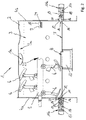
- Fig. 1 and 2 show a designated as a whole with 1 bulk solids mixer for dry and / or free-flowing bulk material having a drum-shaped mixing container 2 with a cylindrical wall 3 and with end walls 4a and 4b and which is designed as a batch mixer.
- the bulk material mixer 1 is designed as a continuous bulk material mixer.
- the following description of the characteristics of the bulk material mixer and of the cleaning method also applies to the bulk material mixer designed as a continuous bulk material mixer and the method for cleaning this continuous bulk material mixer.
- the bulk material can be introduced into the mixing container 2 through an opening 1a provided in the position of use of the bulk material mixer 1 at the top of the mixing container 2.
- a spaced apart from the two end-side end walls 4a and 4b outlet opening 8 for discharging a finished mixture of the mixing container 2 is provided.
- the bulk material mixer 1 for example, dry and / or pourable building material mixtures, such as wall plasters, finished plasters, screeds or the like can be mixed.
- the raw materials of these building material mixtures are supplied to the bulk material mixer 1 through the opening 1a in a dry, free-flowing form as bulk material in certain proportions and mixed inside the mixing container 2 by means of mixing tools 6 of the mixer shaft 5 and after completion of the mixing process or after mixing Bulk material discharged through the bottom outlet opening 8 of the mixing container and further processed and / or packaged.
- inlet openings 9 opening into the mixing container 2 on the inner wall side are provided with compressed air nozzles 10 positioned in the inlet openings 9 for introducing compressed air into the mixing container 2 above the outlet opening 8 and adjacent to one of the two end walls 4 a or 4b.
- the inlet openings 9 are designed so that flows through them in the mixing tank 2 incoming compressed air on the inside 3a of the wall 3 of the mixing container 2 in the direction of the bottom portion 7 and on the inside 3a of the wall 3 of the mixing container 2 adhering bulk or mixture residues of the Inner side 3 a of the wall 3 dissolves and transported in the bottom portion 7 of the mixing container 2 and to the outlet opening 8.
- an end-side inlet opening 11 and a compressed-air nozzle 12 arranged in the front-side inlet opening 11 are provided on each of the two end-side end walls 4a and 4b of the mixing container 2 the mixing container 2 incoming compressed air along the bottom portion 7 in the direction of the outlet opening 8 can flow.
- the remaining in the bottom region 7 after emptying the mixing container bulk material can be transported by means of compressed air to the outlet opening 8 of the mixing container 2 and discharged through this from the mixing container 2.
- the four inner-wall-side inlet openings 9 and the compressed-air nozzles 10 arranged in these inlet openings 9 can, together with the front-side inlet openings 11 and the compressed-air nozzles 12 associated therewith, after a completed mixing operation and emptying of the mixing container 2 on the inside 3a of the wall 3 of the mixing container 2 adhering bulk material detach from the inside 3a of the wall 3 and remove almost without residue from the mixing container 2 through the outlet opening 8 of the mixing container 2.
- a pressure sink 13 is also connected.
- the arrow PF3 at the pressure sink 13 indicates the direction of conveyance of the pressure sink 13 and the direction of a suction applied to the outlet opening 8 suction.
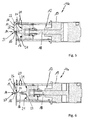
- each of the air outlet openings 14 own, even in the FIGS. 5 and 6 shown air supply channel 15, whose cross section is as circular as the cross section of the air outlet opening. It can also be seen that a distance between two adjacent air outlet openings 14 of the front-side inlet openings 11 of the bulk material mixer 1 is greater than a diameter of the air outlet openings 14.
- the length of the air supply channels 15 of the individual air outlet openings 14 is at least one centimeter. This is favorable, so that as sharply defined and as far as possible compressed air jets can form.
- Fig. 1 shows that a total width of the horizontally juxtaposed in a row adjacent air outlet openings 14 of the front-side inlet openings 11 and the front-side compressed air nozzles 12 is smaller than one of the frontal inlet opening 11 facing width of the bottom outlet opening 8 of the mixing container 2.
- the family of arrows PF2 which illustrate the bottom-side compressed air flows, shows that the total width is approximately one quarter of the width of the bottom-side outlet opening 8 facing the inlet opening 11.
- the juxtaposed air outlet openings 14 of the front inlet openings are not horizontal, as in the FIGS. 1 and 2 shown, but a curvature of the bottom portion 7 of the mixing container 2 following at the respective end-side end wall 4a and 4b arranged.
- Fig. 3 to 6 show that the individual air outlet openings 14 of the front-side inlet openings 11 and the front-side compressed air nozzles 12 are closed in the non-use position by locking pins 16, wherein the outer cross section of the closure pins 16 corresponds approximately to the inner cross section of the air outlet openings 14.
- closure pins 16 are adjustable in the direction of their longitudinal extent and, in particular, can be introduced into and withdrawn from the air supply channels 15 in the air supply channels 15.
- the two compressed air supply units 11a to be recognized in the figures are mounted on the outside on the end-side end walls 4a and 4b via a respective flange 11b and are positioned in each case in an end-side inlet opening 11.
- the positioned in the inlet openings 11 ends of the two Druckbuchzu brieflyticianen 11a each have one of the two in the use position frontally directed into the mixing container 2 compressed air nozzles 12.
- a linear drive 17 is provided per frontal inlet opening 11 or per end compressed air nozzle 12 as part of the compressed air supply unit 11a, which in the present exemplary embodiment is designed as a pneumatic piston 18 which can be displaced with compressed air in a pneumatic cylinder 19.
- Each of the two pneumatic cylinders 19 has a Druck Kunststoffzu Geneva Surgery 20 for a compressed air supply to the front inlet openings 11 and for a compressed air supply to the front compressed air nozzles 12, in a region between an end face 21 of the pneumatic piston 18 for the adjustment of the closure pins 16 and the air outlet openings 14 of the front inlet openings 11 and the front-side compressed air nozzles 12 is arranged opening.
- the closure pins 14 for the front-side inlet openings 11 and / or the front-side compressed air nozzles 12 of the bulk material mixer 1 are provided at an inlet openings 22 in the air supply channels 15 in the use position facing end face 21 of the pneumatic piston 18.
- the locking pins 14 are on a spacer bar 23, which protrudes relative to the end face 21 of the pneumatic piston 18, arranged on the pneumatic piston 18.
- the compressed-air nozzles 10 positioned in the inner-wall-side inlet openings 9 are designed as flat-jet nozzles 24 which guide the compressed-air flow emerging from them along the inner side 3a of the wall 3 of the mixing container 2 and, as indicated by the arrows PF1 in FIG Fig. 1 recognizable fanned, so that a large portion of the inner side 3 a of the wall 3 of the mixing container can be detected by the compressed air flows injected into the mixing container 2 via the inner side inlet openings 9.
- the inner wall side inlet openings 9 and the compressed air nozzles 10 positioned therein can also be adapted to pivot compressed air streams along the inside 3a of the wall 3 and the mixing vessel in this way with a compressed air jet, for example by means of a pivotable compressed air nozzle on the Inner side 3a of the wall 3 of the mixing container is guided to solve on the inside 3a adhering bulk material or adhering mixture residues and to remove from the mixing container 2.
- the compressed-air nozzles 10 positioned in the inner-wall-side inlet openings 9 are configured and arranged at a distance from one another such that they direct the respective compressed-air flow along the inner side 3a of the wall 3 of the mixing container 2 into a region 25, into which a compressed-air flow of an adjacent one in particular inside wall-side inlet opening 9 and a compressed air nozzle 10 passes.
- At least one further inlet opening and / or a compressed air nozzle positioned therein is provided between two inlet openings 9 opening on the inner wall side, whose compressed air flow in each case crosses and / or supplements the compressed air flow coming from the inlet openings 9 adjacent thereto and the compressed air nozzles 10 positioned therein.
- Fig. 3 to 6 show that the inflow-side inlet openings 22 are sunk into the air supply ducts 15 of the air outlet openings 14 of the inlet openings 11 of the bulk material mixer 1 and have an insertion bevel 26 for easier insertion of the closure pins 16 into the inlet openings 22 of the air supply channels 15.
- the finished mixture is discharged through the outlet opening 8 of the mixing container 2 from the mixing container 2.
- bulk material may adhere to the inside 3a of the wall 3 of the mixing container 2, which may necessitate a cleaning of the mixing container 2 before a next subsequent mixing operation is carried out.
- the mixing container 2 is cleaned by pressurizing and / or blowing on the inside 3a of the wall 3 of the mixing container 2 for dissolving adhering bulk material. Thereafter, the dissolved bulk material is discharged from the mixing container 2 via the outlet opening 8 arranged on the bottom side and at a distance from the two end-side end walls 4a and 4b of the mixing container 2.
- the peculiarity of the cleaning method consists in the fact that the inside 3a of the mixing container 2 of a plurality of stationary, spaced above the outlet opening 8 arranged locations, namely from the front inlet openings 11 and the therein positioned front compressed air nozzles 12 and from the inside wall opening side inlet openings 9 and from the inside wall side emptying and positioned in the inlet openings 9 compressed air nozzles 10, is blown and acted upon by the compressed air and the resulting bulk material is conveyed out of the outlet opening 8 and discharged.
- the compressed air is in the form of compressed air streams in Fig. 1 are illustrated with the arrows PF1 and PF2, of a total of four stationary, spaced from each other, the inner wall side opening and above the outlet opening arranged points, namely from the four inner wall side opening into the mixing container 2 inlet openings 9 and the compressed air nozzles 10 positioned therein along the inside 3a of the wall 3 of the mixing container 2 in the direction of the bottom portion 7 of the mixing container 2 and to the outlet opening 8 to the inside 3a of the mixing container 2 blown to detach adhering bulk material.
- all of the compressed air streams PF1 and PF2 are blown into the mixing container 2 from the different points simultaneously or else with a time delay.
- a delayed injection of the compressed air streams into the mixing container 2 for example, first the inside air side introduced compressed air streams, which illustrates with the arrows PF1 are, and time-shifted to the front side introduced, ground-level, with PF2 designated compressed air streams are blown.
- the compressed air streams with different intensity and / or pulsating blown and / or can be mechanically and / or automatically pivoted during the blowing over the inside 3a of the wall 3 of the mixing container 2 to better adhering bulk material from the inside of the 3a Wall 3 of the mixing container 2 to be able to solve.
- the front side blown into the mixing container 2 compressed air streams are injected as a plurality of parallel and / or isolated compressed air streams in the mixing container 2 to the outlet opening 8 of the mixing container 2 in this.
- the compressed air flows PF1 introduced on the inner wall side are blown into the mixing container 2 at the level of the mixer shaft 5 which extends horizontally through the mixing container 2, in which the inlet openings 9 opening on the inner wall side and the compressed air nozzles 10 positioned therein are arranged on the inner side 3a of the wall 3 of the mixing container 2 ,
- the bulk material mixer 1 comprises a mixing container 2 with a cylindrical or trough-shaped wall 3 and with end-side end walls 4a and 4b. Further, in the mixing container 2 of the bulk material mixer 1, a coaxial with the mixing container 2 arranged mixer shaft 5 is provided, the spaced apart from the inside 3a of the wall 3 of the mixing container 2 rotating mixing tools 6 and one in the bottom portion 7 of the mixing container 2 spaced to the end-side end walls 4a and 4b arranged Having outlet for discharging a finished mixture consisting of dry and / or free-flowing bulk material from the mixing container 2.
- the compressed air flowing into the mixing container 2 from the inlet side 9 opening into the mixing container 2 flows along the inner side 3a of the wall 3 of the mixing container 2 in the direction of the bottom region 7 and / or to the outlet opening 8.
- the bulk material mixer 1 adjoins the two end faces End walls 4a and 4b each have an end inlet opening 11 with a placed therein, the front side opening into the mixing tank 2 compressed air nozzle 12, so that from the frontal inlet openings 11 and from the frontal compressed air nozzles 12 in the mixing tank 2 incoming compressed air along the bottom portion 7 to the outlet opening 8 flows and thereby removed from the inside 3a of the mixing container 2 dissolved bulk material through the outlet opening 8 from the mixing container 2.
Landscapes
- Chemical & Material Sciences (AREA)
- Chemical Kinetics & Catalysis (AREA)
- Engineering & Computer Science (AREA)
- Mechanical Engineering (AREA)
- Accessories For Mixers (AREA)
- Nozzles (AREA)
- Processing And Handling Of Plastics And Other Materials For Molding In General (AREA)
- Air Transport Of Granular Materials (AREA)
Applications Claiming Priority (1)
| Application Number | Priority Date | Filing Date | Title |
|---|---|---|---|
| DE102013204491.7A DE102013204491A1 (de) | 2013-03-14 | 2013-03-14 | Reinigungsverfahren für einen Schüttgutmischer sowie Schüttgutmischer mit zu reinigendem Mischbehälter |
Publications (2)
| Publication Number | Publication Date |
|---|---|
| EP2777831A1 true EP2777831A1 (fr) | 2014-09-17 |
| EP2777831B1 EP2777831B1 (fr) | 2017-03-15 |
Family
ID=49958231
Family Applications (1)
| Application Number | Title | Priority Date | Filing Date |
|---|---|---|---|
| EP14000140.5A Active EP2777831B1 (fr) | 2013-03-14 | 2014-01-15 | Procédé de nettoyage pour un mélangeur de produits en vrac et mélangeur de produits en vrac doté d'un récipient de mélange à nettoyer |
Country Status (5)
| Country | Link |
|---|---|
| EP (1) | EP2777831B1 (fr) |
| CN (1) | CN204159248U (fr) |
| BR (1) | BR102014005677A2 (fr) |
| DE (1) | DE102013204491A1 (fr) |
| RU (1) | RU2651163C2 (fr) |
Cited By (2)
| Publication number | Priority date | Publication date | Assignee | Title |
|---|---|---|---|---|
| WO2019075830A1 (fr) * | 2017-10-17 | 2019-04-25 | 苏州宏泉高压电容器有限公司 | Dispositif d'agitation de mélange-maître de couleur à haut rendement de type basculant |
| EP4019153A1 (fr) * | 2020-12-22 | 2022-06-29 | Tetra Laval Holdings & Finance S.A. | Buse à jet pour appareil de manipulation de poudre |
Families Citing this family (1)
| Publication number | Priority date | Publication date | Assignee | Title |
|---|---|---|---|---|
| CN105056783A (zh) * | 2015-07-30 | 2015-11-18 | 南京萨伯工业设计研究院有限公司 | 粉状物混合设备 |
Citations (4)
| Publication number | Priority date | Publication date | Assignee | Title |
|---|---|---|---|---|
| US3138167A (en) * | 1963-06-18 | 1964-06-23 | Sprout Waldron & Co Inc | Mixer for feeds and the like |
| DE1432998A1 (de) * | 1964-04-24 | 1969-10-23 | Fritz Loedige | Vorrichtung zum Reinigen eines Mischbehaelters od.dgl. |
| EP0358120A2 (fr) * | 1988-09-07 | 1990-03-14 | Werner Lüber | Installation de malaxage pour produits granulés, notamment pour du sable à noyaux |
| DE102010025749A1 (de) * | 2010-06-30 | 2012-01-05 | Illinois Tool Works Inc. | Pulverversorgungsvorrichtung für eine Pulverbeschichtungsanlage |
Family Cites Families (3)
| Publication number | Priority date | Publication date | Assignee | Title |
|---|---|---|---|---|
| RU2150341C1 (ru) * | 1999-10-06 | 2000-06-10 | Ист Вест Инвеншнз энд Текнолоджи ПТВ Лтд. | Способ очистки резервуаров для нефти и темных нефтепродуктов с утилизацией продуктов очистки |
| RU2200066C2 (ru) * | 2001-04-10 | 2003-03-10 | Анатолий Никитович Жилин | Способ очистки емкостей от твердых сыпучих материалов и устройство для реализации этого способа |
| US7011047B2 (en) * | 2003-11-20 | 2006-03-14 | United Technologies Corporation | Detonative cleaning apparatus |
-
2013
- 2013-03-14 DE DE102013204491.7A patent/DE102013204491A1/de not_active Withdrawn
-
2014
- 2014-01-15 EP EP14000140.5A patent/EP2777831B1/fr active Active
- 2014-03-11 RU RU2014108958A patent/RU2651163C2/ru active
- 2014-03-12 BR BRBR102014005677-7A patent/BR102014005677A2/pt not_active Application Discontinuation
- 2014-03-13 CN CN201420115472.7U patent/CN204159248U/zh not_active Expired - Lifetime
Patent Citations (4)
| Publication number | Priority date | Publication date | Assignee | Title |
|---|---|---|---|---|
| US3138167A (en) * | 1963-06-18 | 1964-06-23 | Sprout Waldron & Co Inc | Mixer for feeds and the like |
| DE1432998A1 (de) * | 1964-04-24 | 1969-10-23 | Fritz Loedige | Vorrichtung zum Reinigen eines Mischbehaelters od.dgl. |
| EP0358120A2 (fr) * | 1988-09-07 | 1990-03-14 | Werner Lüber | Installation de malaxage pour produits granulés, notamment pour du sable à noyaux |
| DE102010025749A1 (de) * | 2010-06-30 | 2012-01-05 | Illinois Tool Works Inc. | Pulverversorgungsvorrichtung für eine Pulverbeschichtungsanlage |
Cited By (3)
| Publication number | Priority date | Publication date | Assignee | Title |
|---|---|---|---|---|
| WO2019075830A1 (fr) * | 2017-10-17 | 2019-04-25 | 苏州宏泉高压电容器有限公司 | Dispositif d'agitation de mélange-maître de couleur à haut rendement de type basculant |
| EP4019153A1 (fr) * | 2020-12-22 | 2022-06-29 | Tetra Laval Holdings & Finance S.A. | Buse à jet pour appareil de manipulation de poudre |
| WO2022136240A1 (fr) * | 2020-12-22 | 2022-06-30 | Tetra Laval Holdings & Finance S.A. | Buse à jet pour appareil de manipulation de poudre |
Also Published As
| Publication number | Publication date |
|---|---|
| RU2651163C2 (ru) | 2018-04-18 |
| DE102013204491A1 (de) | 2014-09-18 |
| RU2014108958A (ru) | 2015-09-20 |
| BR102014005677A2 (pt) | 2015-07-14 |
| EP2777831B1 (fr) | 2017-03-15 |
| CN204159248U (zh) | 2015-02-18 |
Similar Documents
| Publication | Publication Date | Title |
|---|---|---|
| DE60012680T2 (de) | Düseneinrichtung | |
| DE1432998C3 (de) | Vorrichtung zum restlosen Entleeren eines Mischbehälters o.dgl | |
| DE3439584C2 (de) | Gerät zum Entfernen von Plaque und Verfärbungen auf Zahnoberflächen | |
| DE202006009786U1 (de) | Milchaufschäumvorrichtung | |
| DE2137058C3 (fr) | ||
| EP3730022B1 (fr) | Élément filtrant | |
| EP2777831B1 (fr) | Procédé de nettoyage pour un mélangeur de produits en vrac et mélangeur de produits en vrac doté d'un récipient de mélange à nettoyer | |
| EP2537484B1 (fr) | Dispositif de mélange pour un pulvérisateur de poudre dentaire | |
| EP0829313B1 (fr) | Installation automatique pour le nettoyage de pièces | |
| DE1287042B (de) | Gaswaescher | |
| EP1967296B1 (fr) | Dispositif de nettoyage de caisses et sol correspondant | |
| DE20305947U1 (de) | Vorrichtung zur Reinigung einer Pulverbeschichtungskabine und Pulverbeschichtungskabine mit Reinigungsvorrichtung | |
| DE2417580A1 (de) | Verfahren und vorrichtung zum richten eines feste abriebpartikel enhaltenden fluessigkeitsstrahls auf die oberflaeche eines werkstuecks | |
| DE19705523C2 (de) | Bepuderungsanlage | |
| DE3112465C2 (de) | Verfahren zum Entfernen von festen Rückständen aus Großbehältern wie Bunkern, Silos, Tanks o.dgl. | |
| DE2107988C3 (de) | Kanalreinigungsgerät | |
| DE10136453A1 (de) | Reinigungseinrichtung einer Pulverbeschichtungskabine | |
| DE19822537A1 (de) | Reinigungsvorrichtung für Karosserien von Fahrzeugen | |
| EP3469909B1 (fr) | Dispositif de pétrissage de pâte fonctionnant en continu | |
| DE2406834A1 (de) | Reinigungsanlage fuer prallreinigung von verunreinigten granulaten | |
| DE102009037358A1 (de) | Reinigungsmaschine für Flaschen oder dergleichen Behälter | |
| DE4035786A1 (de) | Blaskopf einer vorrichtung zum waschen von halbleitermaterialien | |
| DE69614774T2 (de) | Vorrichtung zur Verteilung von pastösen Produkten, wie Putz oder Mörtel, insbesondere für Bauwerke | |
| DE388215C (de) | Verfahren und Einrichtung zum Entleeren von Massenbehaeltern aller Art | |
| DE2641565A1 (de) | Ziehvorrichtung |
Legal Events
| Date | Code | Title | Description |
|---|---|---|---|
| PUAI | Public reference made under article 153(3) epc to a published international application that has entered the european phase |
Free format text: ORIGINAL CODE: 0009012 |
|
| 17P | Request for examination filed |
Effective date: 20140115 |
|
| AK | Designated contracting states |
Kind code of ref document: A1 Designated state(s): AL AT BE BG CH CY CZ DE DK EE ES FI FR GB GR HR HU IE IS IT LI LT LU LV MC MK MT NL NO PL PT RO RS SE SI SK SM TR |
|
| AX | Request for extension of the european patent |
Extension state: BA ME |
|
| R17P | Request for examination filed (corrected) |
Effective date: 20140903 |
|
| RBV | Designated contracting states (corrected) |
Designated state(s): AL AT BE BG CH CY CZ DE DK EE ES FI FR GB GR HR HU IE IS IT LI LT LU LV MC MK MT NL NO PL PT RO RS SE SI SK SM TR |
|
| GRAP | Despatch of communication of intention to grant a patent |
Free format text: ORIGINAL CODE: EPIDOSNIGR1 |
|
| RIC1 | Information provided on ipc code assigned before grant |
Ipc: B01F 7/04 20060101ALI20160610BHEP Ipc: B08B 9/08 20060101ALI20160610BHEP Ipc: B01F 7/00 20060101ALI20160610BHEP Ipc: B01F 15/00 20060101ALI20160610BHEP Ipc: B08B 5/02 20060101AFI20160610BHEP |
|
| INTG | Intention to grant announced |
Effective date: 20160708 |
|
| GRAS | Grant fee paid |
Free format text: ORIGINAL CODE: EPIDOSNIGR3 |
|
| GRAJ | Information related to disapproval of communication of intention to grant by the applicant or resumption of examination proceedings by the epo deleted |
Free format text: ORIGINAL CODE: EPIDOSDIGR1 |
|
| GRAL | Information related to payment of fee for publishing/printing deleted |
Free format text: ORIGINAL CODE: EPIDOSDIGR3 |
|
| GRAP | Despatch of communication of intention to grant a patent |
Free format text: ORIGINAL CODE: EPIDOSNIGR1 |
|
| INTC | Intention to grant announced (deleted) | ||
| INTG | Intention to grant announced |
Effective date: 20161201 |
|
| GRAA | (expected) grant |
Free format text: ORIGINAL CODE: 0009210 |
|
| AK | Designated contracting states |
Kind code of ref document: B1 Designated state(s): AL AT BE BG CH CY CZ DE DK EE ES FI FR GB GR HR HU IE IS IT LI LT LU LV MC MK MT NL NO PL PT RO RS SE SI SK SM TR |
|
| REG | Reference to a national code |
Ref country code: CH Ref legal event code: EP Ref country code: GB Ref legal event code: FG4D Free format text: NOT ENGLISH |
|
| REG | Reference to a national code |
Ref country code: IE Ref legal event code: FG4D Free format text: LANGUAGE OF EP DOCUMENT: GERMAN |
|
| REG | Reference to a national code |
Ref country code: AT Ref legal event code: REF Ref document number: 875011 Country of ref document: AT Kind code of ref document: T Effective date: 20170415 |
|
| REG | Reference to a national code |
Ref country code: DE Ref legal event code: R096 Ref document number: 502014002960 Country of ref document: DE |
|
| REG | Reference to a national code |
Ref country code: NL Ref legal event code: MP Effective date: 20170315 |
|
| REG | Reference to a national code |
Ref country code: LT Ref legal event code: MG4D |
|
| PG25 | Lapsed in a contracting state [announced via postgrant information from national office to epo] |
Ref country code: LT Free format text: LAPSE BECAUSE OF FAILURE TO SUBMIT A TRANSLATION OF THE DESCRIPTION OR TO PAY THE FEE WITHIN THE PRESCRIBED TIME-LIMIT Effective date: 20170315 Ref country code: NO Free format text: LAPSE BECAUSE OF FAILURE TO SUBMIT A TRANSLATION OF THE DESCRIPTION OR TO PAY THE FEE WITHIN THE PRESCRIBED TIME-LIMIT Effective date: 20170615 Ref country code: FI Free format text: LAPSE BECAUSE OF FAILURE TO SUBMIT A TRANSLATION OF THE DESCRIPTION OR TO PAY THE FEE WITHIN THE PRESCRIBED TIME-LIMIT Effective date: 20170315 Ref country code: GR Free format text: LAPSE BECAUSE OF FAILURE TO SUBMIT A TRANSLATION OF THE DESCRIPTION OR TO PAY THE FEE WITHIN THE PRESCRIBED TIME-LIMIT Effective date: 20170616 Ref country code: HR Free format text: LAPSE BECAUSE OF FAILURE TO SUBMIT A TRANSLATION OF THE DESCRIPTION OR TO PAY THE FEE WITHIN THE PRESCRIBED TIME-LIMIT Effective date: 20170315 |
|
| PG25 | Lapsed in a contracting state [announced via postgrant information from national office to epo] |
Ref country code: BG Free format text: LAPSE BECAUSE OF FAILURE TO SUBMIT A TRANSLATION OF THE DESCRIPTION OR TO PAY THE FEE WITHIN THE PRESCRIBED TIME-LIMIT Effective date: 20170615 Ref country code: SE Free format text: LAPSE BECAUSE OF FAILURE TO SUBMIT A TRANSLATION OF THE DESCRIPTION OR TO PAY THE FEE WITHIN THE PRESCRIBED TIME-LIMIT Effective date: 20170315 Ref country code: LV Free format text: LAPSE BECAUSE OF FAILURE TO SUBMIT A TRANSLATION OF THE DESCRIPTION OR TO PAY THE FEE WITHIN THE PRESCRIBED TIME-LIMIT Effective date: 20170315 Ref country code: RS Free format text: LAPSE BECAUSE OF FAILURE TO SUBMIT A TRANSLATION OF THE DESCRIPTION OR TO PAY THE FEE WITHIN THE PRESCRIBED TIME-LIMIT Effective date: 20170315 |
|
| PG25 | Lapsed in a contracting state [announced via postgrant information from national office to epo] |
Ref country code: NL Free format text: LAPSE BECAUSE OF FAILURE TO SUBMIT A TRANSLATION OF THE DESCRIPTION OR TO PAY THE FEE WITHIN THE PRESCRIBED TIME-LIMIT Effective date: 20170315 |
|
| PG25 | Lapsed in a contracting state [announced via postgrant information from national office to epo] |
Ref country code: CZ Free format text: LAPSE BECAUSE OF FAILURE TO SUBMIT A TRANSLATION OF THE DESCRIPTION OR TO PAY THE FEE WITHIN THE PRESCRIBED TIME-LIMIT Effective date: 20170315 Ref country code: EE Free format text: LAPSE BECAUSE OF FAILURE TO SUBMIT A TRANSLATION OF THE DESCRIPTION OR TO PAY THE FEE WITHIN THE PRESCRIBED TIME-LIMIT Effective date: 20170315 Ref country code: RO Free format text: LAPSE BECAUSE OF FAILURE TO SUBMIT A TRANSLATION OF THE DESCRIPTION OR TO PAY THE FEE WITHIN THE PRESCRIBED TIME-LIMIT Effective date: 20170315 Ref country code: ES Free format text: LAPSE BECAUSE OF FAILURE TO SUBMIT A TRANSLATION OF THE DESCRIPTION OR TO PAY THE FEE WITHIN THE PRESCRIBED TIME-LIMIT Effective date: 20170315 Ref country code: SK Free format text: LAPSE BECAUSE OF FAILURE TO SUBMIT A TRANSLATION OF THE DESCRIPTION OR TO PAY THE FEE WITHIN THE PRESCRIBED TIME-LIMIT Effective date: 20170315 |
|
| PG25 | Lapsed in a contracting state [announced via postgrant information from national office to epo] |
Ref country code: PT Free format text: LAPSE BECAUSE OF FAILURE TO SUBMIT A TRANSLATION OF THE DESCRIPTION OR TO PAY THE FEE WITHIN THE PRESCRIBED TIME-LIMIT Effective date: 20170717 Ref country code: PL Free format text: LAPSE BECAUSE OF FAILURE TO SUBMIT A TRANSLATION OF THE DESCRIPTION OR TO PAY THE FEE WITHIN THE PRESCRIBED TIME-LIMIT Effective date: 20170315 Ref country code: SM Free format text: LAPSE BECAUSE OF FAILURE TO SUBMIT A TRANSLATION OF THE DESCRIPTION OR TO PAY THE FEE WITHIN THE PRESCRIBED TIME-LIMIT Effective date: 20170315 Ref country code: IS Free format text: LAPSE BECAUSE OF FAILURE TO SUBMIT A TRANSLATION OF THE DESCRIPTION OR TO PAY THE FEE WITHIN THE PRESCRIBED TIME-LIMIT Effective date: 20170715 |
|
| REG | Reference to a national code |
Ref country code: DE Ref legal event code: R097 Ref document number: 502014002960 Country of ref document: DE |
|
| PLBE | No opposition filed within time limit |
Free format text: ORIGINAL CODE: 0009261 |
|
| STAA | Information on the status of an ep patent application or granted ep patent |
Free format text: STATUS: NO OPPOSITION FILED WITHIN TIME LIMIT |
|
| PG25 | Lapsed in a contracting state [announced via postgrant information from national office to epo] |
Ref country code: DK Free format text: LAPSE BECAUSE OF FAILURE TO SUBMIT A TRANSLATION OF THE DESCRIPTION OR TO PAY THE FEE WITHIN THE PRESCRIBED TIME-LIMIT Effective date: 20170315 |
|
| 26N | No opposition filed |
Effective date: 20171218 |
|
| PG25 | Lapsed in a contracting state [announced via postgrant information from national office to epo] |
Ref country code: SI Free format text: LAPSE BECAUSE OF FAILURE TO SUBMIT A TRANSLATION OF THE DESCRIPTION OR TO PAY THE FEE WITHIN THE PRESCRIBED TIME-LIMIT Effective date: 20170315 |
|
| REG | Reference to a national code |
Ref country code: CH Ref legal event code: PL |
|
| PG25 | Lapsed in a contracting state [announced via postgrant information from national office to epo] |
Ref country code: MT Free format text: LAPSE BECAUSE OF FAILURE TO SUBMIT A TRANSLATION OF THE DESCRIPTION OR TO PAY THE FEE WITHIN THE PRESCRIBED TIME-LIMIT Effective date: 20170315 |
|
| PG25 | Lapsed in a contracting state [announced via postgrant information from national office to epo] |
Ref country code: LU Free format text: LAPSE BECAUSE OF NON-PAYMENT OF DUE FEES Effective date: 20180115 Ref country code: FR Free format text: LAPSE BECAUSE OF NON-PAYMENT OF DUE FEES Effective date: 20180131 |
|
| REG | Reference to a national code |
Ref country code: IE Ref legal event code: MM4A |
|
| REG | Reference to a national code |
Ref country code: FR Ref legal event code: ST Effective date: 20180928 |
|
| REG | Reference to a national code |
Ref country code: BE Ref legal event code: MM Effective date: 20180131 |
|
| PG25 | Lapsed in a contracting state [announced via postgrant information from national office to epo] |
Ref country code: LI Free format text: LAPSE BECAUSE OF NON-PAYMENT OF DUE FEES Effective date: 20180131 Ref country code: CH Free format text: LAPSE BECAUSE OF NON-PAYMENT OF DUE FEES Effective date: 20180131 Ref country code: BE Free format text: LAPSE BECAUSE OF NON-PAYMENT OF DUE FEES Effective date: 20180131 |
|
| PG25 | Lapsed in a contracting state [announced via postgrant information from national office to epo] |
Ref country code: IE Free format text: LAPSE BECAUSE OF NON-PAYMENT OF DUE FEES Effective date: 20180115 |
|
| PG25 | Lapsed in a contracting state [announced via postgrant information from national office to epo] |
Ref country code: MC Free format text: LAPSE BECAUSE OF FAILURE TO SUBMIT A TRANSLATION OF THE DESCRIPTION OR TO PAY THE FEE WITHIN THE PRESCRIBED TIME-LIMIT Effective date: 20170315 |
|
| PG25 | Lapsed in a contracting state [announced via postgrant information from national office to epo] |
Ref country code: TR Free format text: LAPSE BECAUSE OF FAILURE TO SUBMIT A TRANSLATION OF THE DESCRIPTION OR TO PAY THE FEE WITHIN THE PRESCRIBED TIME-LIMIT Effective date: 20170315 |
|
| PG25 | Lapsed in a contracting state [announced via postgrant information from national office to epo] |
Ref country code: HU Free format text: LAPSE BECAUSE OF FAILURE TO SUBMIT A TRANSLATION OF THE DESCRIPTION OR TO PAY THE FEE WITHIN THE PRESCRIBED TIME-LIMIT; INVALID AB INITIO Effective date: 20140115 |
|
| PG25 | Lapsed in a contracting state [announced via postgrant information from national office to epo] |
Ref country code: MK Free format text: LAPSE BECAUSE OF NON-PAYMENT OF DUE FEES Effective date: 20170315 Ref country code: CY Free format text: LAPSE BECAUSE OF FAILURE TO SUBMIT A TRANSLATION OF THE DESCRIPTION OR TO PAY THE FEE WITHIN THE PRESCRIBED TIME-LIMIT Effective date: 20170315 |
|
| PG25 | Lapsed in a contracting state [announced via postgrant information from national office to epo] |
Ref country code: AL Free format text: LAPSE BECAUSE OF FAILURE TO SUBMIT A TRANSLATION OF THE DESCRIPTION OR TO PAY THE FEE WITHIN THE PRESCRIBED TIME-LIMIT Effective date: 20170315 |
|
| PGFP | Annual fee paid to national office [announced via postgrant information from national office to epo] |
Ref country code: AT Payment date: 20240118 Year of fee payment: 11 |
|
| PGFP | Annual fee paid to national office [announced via postgrant information from national office to epo] |
Ref country code: DE Payment date: 20240205 Year of fee payment: 11 Ref country code: GB Payment date: 20240124 Year of fee payment: 11 |
|
| PGFP | Annual fee paid to national office [announced via postgrant information from national office to epo] |
Ref country code: IT Payment date: 20240131 Year of fee payment: 11 |