EP2777128B1 - Electronic apparatus and transmission system - Google Patents
Electronic apparatus and transmission system Download PDFInfo
- Publication number
- EP2777128B1 EP2777128B1 EP12821066.3A EP12821066A EP2777128B1 EP 2777128 B1 EP2777128 B1 EP 2777128B1 EP 12821066 A EP12821066 A EP 12821066A EP 2777128 B1 EP2777128 B1 EP 2777128B1
- Authority
- EP
- European Patent Office
- Prior art keywords
- signal
- power
- frequency component
- data
- received signal
- Prior art date
- Legal status (The legal status is an assumption and is not a legal conclusion. Google has not performed a legal analysis and makes no representation as to the accuracy of the status listed.)
- Active
Links
- 230000005540 biological transmission Effects 0.000 title claims description 143
- 238000001514 detection method Methods 0.000 claims description 94
- 238000000034 method Methods 0.000 claims description 27
- 238000012545 processing Methods 0.000 claims description 14
- 230000006698 induction Effects 0.000 claims description 7
- 239000003990 capacitor Substances 0.000 description 25
- 230000000052 comparative effect Effects 0.000 description 19
- 238000004891 communication Methods 0.000 description 14
- 230000009467 reduction Effects 0.000 description 11
- 238000010586 diagram Methods 0.000 description 10
- 230000008569 process Effects 0.000 description 8
- 102100035954 Choline transporter-like protein 2 Human genes 0.000 description 6
- 101000948115 Homo sapiens Choline transporter-like protein 2 Proteins 0.000 description 6
- 102100031699 Choline transporter-like protein 1 Human genes 0.000 description 5
- 101000940912 Homo sapiens Choline transporter-like protein 1 Proteins 0.000 description 5
- 230000004907 flux Effects 0.000 description 5
- 230000005674 electromagnetic induction Effects 0.000 description 4
- 238000005516 engineering process Methods 0.000 description 4
- 238000012986 modification Methods 0.000 description 3
- 230000004048 modification Effects 0.000 description 3
- 230000009351 contact transmission Effects 0.000 description 2
- 230000004044 response Effects 0.000 description 2
- 238000004804 winding Methods 0.000 description 2
- HBBGRARXTFLTSG-UHFFFAOYSA-N Lithium ion Chemical compound [Li+] HBBGRARXTFLTSG-UHFFFAOYSA-N 0.000 description 1
- 230000002457 bidirectional effect Effects 0.000 description 1
- 230000033228 biological regulation Effects 0.000 description 1
- 230000008859 change Effects 0.000 description 1
- 239000000356 contaminant Substances 0.000 description 1
- 230000008878 coupling Effects 0.000 description 1
- 238000010168 coupling process Methods 0.000 description 1
- 238000005859 coupling reaction Methods 0.000 description 1
- 230000003247 decreasing effect Effects 0.000 description 1
- 230000001419 dependent effect Effects 0.000 description 1
- 238000013461 design Methods 0.000 description 1
- 230000000694 effects Effects 0.000 description 1
- 230000002708 enhancing effect Effects 0.000 description 1
- 230000005669 field effect Effects 0.000 description 1
- 229910001416 lithium ion Inorganic materials 0.000 description 1
- 238000004519 manufacturing process Methods 0.000 description 1
- 239000002184 metal Substances 0.000 description 1
- 239000004065 semiconductor Substances 0.000 description 1
Images


Classifications
-
- H—ELECTRICITY
- H04—ELECTRIC COMMUNICATION TECHNIQUE
- H04B—TRANSMISSION
- H04B5/00—Near-field transmission systems, e.g. inductive or capacitive transmission systems
- H04B5/70—Near-field transmission systems, e.g. inductive or capacitive transmission systems specially adapted for specific purposes
- H04B5/79—Near-field transmission systems, e.g. inductive or capacitive transmission systems specially adapted for specific purposes for data transfer in combination with power transfer
-
- H—ELECTRICITY
- H02—GENERATION; CONVERSION OR DISTRIBUTION OF ELECTRIC POWER
- H02J—CIRCUIT ARRANGEMENTS OR SYSTEMS FOR SUPPLYING OR DISTRIBUTING ELECTRIC POWER; SYSTEMS FOR STORING ELECTRIC ENERGY
- H02J50/00—Circuit arrangements or systems for wireless supply or distribution of electric power
- H02J50/50—Circuit arrangements or systems for wireless supply or distribution of electric power using additional energy repeaters between transmitting devices and receiving devices
-
- H—ELECTRICITY
- H02—GENERATION; CONVERSION OR DISTRIBUTION OF ELECTRIC POWER
- H02J—CIRCUIT ARRANGEMENTS OR SYSTEMS FOR SUPPLYING OR DISTRIBUTING ELECTRIC POWER; SYSTEMS FOR STORING ELECTRIC ENERGY
- H02J50/00—Circuit arrangements or systems for wireless supply or distribution of electric power
- H02J50/10—Circuit arrangements or systems for wireless supply or distribution of electric power using inductive coupling
- H02J50/12—Circuit arrangements or systems for wireless supply or distribution of electric power using inductive coupling of the resonant type
-
- H—ELECTRICITY
- H02—GENERATION; CONVERSION OR DISTRIBUTION OF ELECTRIC POWER
- H02J—CIRCUIT ARRANGEMENTS OR SYSTEMS FOR SUPPLYING OR DISTRIBUTING ELECTRIC POWER; SYSTEMS FOR STORING ELECTRIC ENERGY
- H02J50/00—Circuit arrangements or systems for wireless supply or distribution of electric power
- H02J50/40—Circuit arrangements or systems for wireless supply or distribution of electric power using two or more transmitting or receiving devices
-
- H—ELECTRICITY
- H02—GENERATION; CONVERSION OR DISTRIBUTION OF ELECTRIC POWER
- H02J—CIRCUIT ARRANGEMENTS OR SYSTEMS FOR SUPPLYING OR DISTRIBUTING ELECTRIC POWER; SYSTEMS FOR STORING ELECTRIC ENERGY
- H02J50/00—Circuit arrangements or systems for wireless supply or distribution of electric power
- H02J50/80—Circuit arrangements or systems for wireless supply or distribution of electric power involving the exchange of data, concerning supply or distribution of electric power, between transmitting devices and receiving devices
-
- H—ELECTRICITY
- H02—GENERATION; CONVERSION OR DISTRIBUTION OF ELECTRIC POWER
- H02J—CIRCUIT ARRANGEMENTS OR SYSTEMS FOR SUPPLYING OR DISTRIBUTING ELECTRIC POWER; SYSTEMS FOR STORING ELECTRIC ENERGY
- H02J50/00—Circuit arrangements or systems for wireless supply or distribution of electric power
- H02J50/90—Circuit arrangements or systems for wireless supply or distribution of electric power involving detection or optimisation of position, e.g. alignment
-
- H—ELECTRICITY
- H02—GENERATION; CONVERSION OR DISTRIBUTION OF ELECTRIC POWER
- H02J—CIRCUIT ARRANGEMENTS OR SYSTEMS FOR SUPPLYING OR DISTRIBUTING ELECTRIC POWER; SYSTEMS FOR STORING ELECTRIC ENERGY
- H02J7/00—Circuit arrangements for charging or depolarising batteries or for supplying loads from batteries
- H02J7/0029—Circuit arrangements for charging or depolarising batteries or for supplying loads from batteries with safety or protection devices or circuits
- H02J7/00308—Overvoltage protection
-
- H—ELECTRICITY
- H02—GENERATION; CONVERSION OR DISTRIBUTION OF ELECTRIC POWER
- H02J—CIRCUIT ARRANGEMENTS OR SYSTEMS FOR SUPPLYING OR DISTRIBUTING ELECTRIC POWER; SYSTEMS FOR STORING ELECTRIC ENERGY
- H02J7/00—Circuit arrangements for charging or depolarising batteries or for supplying loads from batteries
- H02J7/0047—Circuit arrangements for charging or depolarising batteries or for supplying loads from batteries with monitoring or indicating devices or circuits
-
- H—ELECTRICITY
- H02—GENERATION; CONVERSION OR DISTRIBUTION OF ELECTRIC POWER
- H02J—CIRCUIT ARRANGEMENTS OR SYSTEMS FOR SUPPLYING OR DISTRIBUTING ELECTRIC POWER; SYSTEMS FOR STORING ELECTRIC ENERGY
- H02J7/00—Circuit arrangements for charging or depolarising batteries or for supplying loads from batteries
- H02J7/00032—Circuit arrangements for charging or depolarising batteries or for supplying loads from batteries characterised by data exchange
- H02J7/00045—Authentication, i.e. circuits for checking compatibility between one component, e.g. a battery or a battery charger, and another component, e.g. a power source
-
- H—ELECTRICITY
- H02—GENERATION; CONVERSION OR DISTRIBUTION OF ELECTRIC POWER
- H02J—CIRCUIT ARRANGEMENTS OR SYSTEMS FOR SUPPLYING OR DISTRIBUTING ELECTRIC POWER; SYSTEMS FOR STORING ELECTRIC ENERGY
- H02J7/00—Circuit arrangements for charging or depolarising batteries or for supplying loads from batteries
- H02J7/0042—Circuit arrangements for charging or depolarising batteries or for supplying loads from batteries characterised by the mechanical construction
- H02J7/0044—Circuit arrangements for charging or depolarising batteries or for supplying loads from batteries characterised by the mechanical construction specially adapted for holding portable devices containing batteries
Definitions
- the present disclosure relates to a transmission system performing non-contact power transmission and non-contact data transmission (power feeding and communication) with use of a magnetic field, and to an electronic apparatus (apparatus to be fed with power, power receiver) applied to such a transmission system.
- a feed system (a non-contact feed system, a wireless charging system) performing non-contact power supply (power transmission) to CE devices (consumer electronics devices) such as mobile phones and mobile music players has attracted attention. Accordingly, charging is allowed to be started by not inserting (connecting) a connector of a power supply such as an AC adapter into a unit but placing an electronic apparatus (a secondary-side unit) on a charging tray (a primary-side unit). In other words, terminal connection between the electronic apparatus and the charging tray is not necessary.
- the methods of performing non-contact power supply in such a way are largely classified into two kinds of techniques.
- the first technique is a well-known electromagnetic induction system.
- a degree of coupling between a power transmission side (a primary side) and a power reception side (a secondary side) is extremely high so that feeding is achievable with high efficiency.
- the second technique is a so-called magnetic resonance system which has characteristics that a magnetic flux shared by the power transmission side and the power reception side may be reduced by actively using resonance phenomenon.
- NFC near field communication
- the NFC is an international standard of wireless communication, and is a wireless communication technology consuming less power.
- the NFC is also an example of the standard in RFID (radio frequency identification, individual identification by radio) technology used mainly in transport facilities and the like in Japan (for example, a standard limited at a used frequency of 13.56 MHz).
- the transmission system incorporating both the non-contact power transmission system and the non-contact data transmission system is proposed in, for example, Japanese Patent Applications No. 2011-172299 , 2010-284065 , and 2005-202721 .
- JP 2011 062008 A a noncontact transmission device is know.
- a transmitting part of the noncontact transmission device transmits a power signal and a communication signal to a receiving part.
- a power receiving part stores power in the receiving part.
- the received communication signal is processed by a communication part so as to transmit the processed data to a function part in the receiving part.
- the receiving part is operated by the power stored in the power receiving part.
- a power reception coil and a data transmission coil are common as a single coil. Therefore, the number (kinds) of coils is allowed to be reduced, and cost reduction and downsizing are achievable. However, it is desirable that the difficulty caused by the difference between the two systems (the power transmission system and the data transmission system) be solved and safety be improved.
- the invention provides an electronic apparatus in accordance with independent claim 1.
- the invention provides a method in accordance with independent claim 13. Further aspects of the invention are set forth in the dependent claims, the drawings and the following description.
- An electronic apparatus includes a switch control section configured to: determine whether a received signal is any one of a power signal and a data signal based on the received signal, and select any one of a power-reception operation and a data-transmission operation based on the determination of the received signal.
- a method of routing a received wireless signal based on a frequency includes: receiving a signal wirelessly from a feed unit via magnetic inductance; applying a first filter to the received signal to generate a first frequency component; applying a second filter to the received signal to generate a second frequency component; routing the received signal to a power-reception operation section if a magnitude of the first frequency component exceeds a first voltage threshold; and routing the received signal to a data-transmission operation section if a magnitude of the second frequency component exceeds a second voltage threshold.
- an electronic system in another embodiment, includes: a transmitter configured to wirelessly transmit a power signal and a data signal; an electronic device wirelessly communicatively coupled to the transmitter, the electronic device including: a switch control section to: determine whether a signal received from the transmitter is the power signal or the data signal based on a frequency component of the received signal; and select any one of a power-reception operation and a data-transmission operation based on the determination of the received signal.
- the electronic device includes an induction coil that is electromagnetically coupled to a second induction coil included within the transmitter.
- the common coil With use of the common coil, the power transmitted through the power transmission with use of a magnetic field is received, and the mutual data transmission with use of a magnetic field is performed.
- the number (kinds) of coils is allowed to be reduced, compared with the case where these operations are performed with use of dedicated coils (a power reception coil and a data transmission coil).
- the switching control of ON/OFF state of each of the first changeover switch on the path between the common coil and the power-reception operation section and the second changeover switch on the path between the common coil and the data-transmission operation section is performed based on the detection results with taking account of the frequency components of the signal received by the common coil from the outside (the feed unit). Accordingly, the circuit (the circuit in the above-described data-transmission operation section, and the like) is prevented from being damaged by the difference between the system configuration at the time of the power transmission and the system configuration at the time of the data transmission.
- the switching control of ON/OFF state of each of the first changeover switch on the path between the common coil and the power-reception operation section and the second changeover switch on the path between the common coil and the data-transmission operation section is performed based on the detection results with taking account of the frequency components of the signal received by the common coil from the outside (the feed unit).
- the circuit is prevented from being damaged by the difference between the system configuration at the time of the power transmission and the system configuration at the time of the data transmission, thereby enhancing safety.
- the safety is allowed to be improved while achieving cost reduction and downsizing.
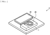
- FIG. 1 illustrates a configuration example of an appearance of a transmission system (a transmission system 4) according to an embodiment of the disclosure
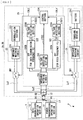
- FIG. 2 illustrates a block configuration example of the transmission system 4.
- the transmission system 4 is a system (a non-contact transmission system) performing non-contact power transmission and non-contact data transmission (power feed and communication) with use of a magnetic field (with use of magnetic resonance, electromagnetic induction, and the like; hereinafter the same).
- the transmission system 4 includes a feed unit 1 (a primary-side unit) and one or more electronic apparatuses (in this example, two electronic apparatuses 2A and 2B; secondary-side units) as units to be fed with power.
- the electronic apparatuses 2A and 2B are placed (or closely disposed) on a feeding surface (power transmission surface) of the feed unit 1 so that the feed unit 1 transmits power to the electronic apparatuses 2A and 2B with use of a magnetic field.
- the feed unit 1 in consideration of the case where power is transmitted to the plurality of electronic apparatuses 2A and 2B at the same time or in a time-divisional manner (sequentially), the feed unit 1 has a mat shape (a tray shape) in which an area of the feeding surface is larger than the size of the electronic apparatuses 2A and 2B to be fed with power.
- the feed unit 1 is a unit (a charging tray) transmitting power to the electronic apparatuses 2A and 2B with use of a magnetic field, and performing mutual data transmission with the electronic apparatuses 2A and 2B.
- the feed unit 1 includes a power-transmission operation section 11, a data-transmission operation section 12, and a common coil L1.
- the common coil L1 is a coil commonly used as a power-transmission coil (a primary-side coil) and a data-transmission coil.
- the power-transmission operation section 11 uses the common coil L1 to transmit power (perform power transmission operation) to the electronic apparatuses 2A and 2B with use of a magnetic field. Specifically, the power-transmission operation section 11 performs power transmission operation radiating a magnetic field (magnetic flux) from the feeding surface toward the electronic apparatuses 2A and 2B.
- the data-transmission operation section 12 uses the common coil L1 to perform mutual data transmission with the electronic apparatuses 2A and 2B (specifically, a data-transmission operation section 22 described later) with use of a magnetic field.
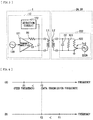
- the data-transmission operation section 12 includes a signal supply source 120, a transmit amplifier 121, a detection circuit 122, a resistor R1, and a capacitor C1.
- the signal supply source 120 supplies predetermined signals for data transmission to the transmit amplifier 121.
- the detection circuit 122 is a circuit detecting presence of signals from the counter party (herein, the data-transmission operation section 22 described later) at the time of data transmission.
- a first end of the resistor R1 is connected to a first output terminal of the transmit amplifier 121, and a second end of the resistor R1 is connected to each of an output terminal of the detection circuit 122, a first end of the capacitor C1, and a first end of the common coil L1.
- a second end of the capacitor C1 is connected to a second output terminal of the transmit amplifier 121 and a second end of the common coil L1.
- the electronic apparatuses 2A and 2B are stationary electronic apparatuses typified by a television receiver, mobile electronic apparatuses including a rechargeable battery (battery), typified by a mobile phone and a digital camera, and the like. As illustrated in FIG. 2 , for example, each of the electronic apparatuses 2A and 2B includes a common coil L2, a changeover switch SW1 (a first changeover switch), a changeover switch SW2 (a second changeover switch), a power-reception operation section 21, the data-transmission operation section 22, and a switch control section 23.
- the common coil L2 is a coil commonly used as a power-reception coil (a secondary-side coil) and a data-transmission coil. In other words, as illustrated by arrows P1 and D1 in FIG. 2 , the common coil L2 receives power transmitted from the common coil L1 in the feed unit 1, and performs mutual data transmission with the common coil L1.
- the power-reception operation section 21 uses the above-described common coil L2 to perform power-reception operation for receiving power transmitted through power transmission with use of a magnetic field, and includes an impedance matching circuit 211, a charging section 212, and a battery 213.
- the impedance matching circuit 211 is a circuit performing impedance matching at the time of power transmission to improve efficiency (transmission efficiency) at the time of power transmission.
- the charging section 212 performs charging with respect to the battery 213, based on power received by the common coil L2.
- the battery 213 stores power therein in response to the charging by the charging section 212, and is configured by using a rechargeable battery (a secondary battery) such as a lithium-ion battery. Note that the detailed configuration example of the impedance matching circuit 211 will be described later ( FIGs. 5A to 5D and FIGs. 6A to 6C ).
- the data-transmission operation section 22 uses the common coil L2 to perform mutual data transmission with the data-transmission operation section 12 in the feed unit 1 with use of a magnetic field, and includes an impedance matching circuit 221 and a demodulation section 222.
- the impedance matching circuit 221 is a circuit performing impedance matching at the time of power transmission, similarly to the above-described impedance matching circuit 211.
- the detailed configuration example of the impedance matching circuit 221 will also be described later ( FIGs. 5A to 5D and FIGs. 6A to 6C ).
- the demodulation section 222 performs demodulation operation at the time of data transmission, and as illustrated in FIG.
- a capacitor C2 for example, includes a capacitor C2, resistors R21 and R22, a transistor Tr2, and a signal supply source 222A.
- a first end of each of the capacitor C2 and the resistors R21 and R22 is connected to a first end of the common coil L2, and a second end of each of the capacitor C2 and the resistor R21 and a source of the transistor Tr2 are connected to a second end of the common coil L2 and grounded.
- a second end of the resistor R22 is connected to a drain of the transistor Tr2, and a gate of the transistor Tr2 is supplied with predetermined signals for demodulation operation from the signal supply source 222A.
- the changeover switch SW1 is disposed on a path (a connection line Lc1) between the common coil L2 and the power-reception operation section 21. Switching of ON/OFF state of the changeover switch SW1 allows the connection state between the common coil L2 and the power-reception operation section 21 to be switched.
- the changeover switch SW2 is disposed on a path (a connection line Lc2) between the common coil L2 and the data-transmission operation section 22. Switching of ON/OFF state of the changeover switch SW2 allows the connection state between the common coil L2 and the data-transmission operation section 22 to be switched.
- each of the changeover switches SW1 and SW2 is configured by using a transistor, a MOSFET (metal-oxide-semiconductor field-effect transistor), and the like.
- the switch control section 23 is disposed on a first end side of a connection line Lc3. A second end side of the connection line Lc3 is connected to the common coil L2.
- the switch control section 23 uses control signals CTL1 and CTL2 to perform switching control of ON/OFF state of each of the above-described changeover switches SW1 and SW2.
- the switch control section 22 performs the switching control of the changeover switches SW1 and SW2, based on detection results with taking account of frequency components of a signal (a carrier) S2 received by the common coil L2 from the outside (in this case, the feed unit 1).
- the switch control section 23 performs such switching control based on a magnitude of a signal level (a voltage and the like) of each of a frequency component for power transmission and a frequency component for data transmission in the signal S2. Note that the detail of the switching control operation by the switch control section 23 will be described later ( FIG. 10 ).
- the switch control section 23 includes an impedance matching circuit 231, two BPFs (band path filters) 232A and 232B, three voltage detection sections 233, 233A, and 233B, and a control section 234.
- BPFs band path filters
- the impedance matching circuit 231 is a circuit performing an impedance matching at the time of power transmission, similarly to the above-described impedance matching circuits 211 and 221. Note that the detailed configuration example of the impedance matching circuit 231 will also be described later ( FIGs. 5A to 5D , and FIGs. 6A to 6C ).
- the BPF 232A (a first filter) is a filter extracting a frequency component for power transmission (a component of a feed frequency f1) from the above-described signal S2, and outputting the extracted component as a signal S21.
- the BPF 232B (a second filter) is a filter extracting a frequency component for data transmission (a component of a data-transmission frequency f2) from the signal S2, and outputting the extracted component as a signal S22.
- the relationship between the feed frequency f1 and the data-transmission frequency f2 is as follows.
- the feed frequency f1 and the data-transmission frequency f2 are different from each other (f1 ⁇ f2), and as illustrated in (A) of FIG. 4 , for example, the feed frequency f1 is lower than the data-transmission frequency f2 (f1 ⁇ f2).
- the feed frequency f1 is higher than the data-transmission frequency f2 (f2 ⁇ f1).
- the case of (A) of FIG. 4 (f1 ⁇ f2) is more preferable than the case of (B) of FIG. 4 (f2 ⁇ f1).
- the feed frequency f1 is a frequency of about 120 kHz or about 6.78 MHz, for example, and the data transmission frequency f2 is 13.56 MHz, for example.
- the voltage detection section 233 detects a signal level (herein, a voltage) of the entire signal S2 (including all of the frequency components) to output a detection result signal J(S2).
- the voltage detection section 233A detects a signal level (herein, a voltage) of the signal S21 (the component of the feed frequency f1 in the signal S2) extracted by the BPF 232A to output a detection result signal J(S21).
- the voltage detection section 233B detects a signal level (herein, a voltage) of the signal S22 (the component of the data-transmission frequency f2 in the signal S2) extracted by the BPF 232B to output a detection result signal J(S22). Note that the detailed configuration example of the voltage detection sections 233, 233A, and 233B will be described later ( FIG. 7 ).
- the control section 234 generates and outputs the control signals CTL1 and CTL2, based on the detection result signals J(S2), J(S21), and J(S22) as the detection results by the voltage detection sections 233, 233A, and 233B, respectively, and accordingly performs switching control of each of the above-described changeover switches SW1 and SW2.
- a control section 234 is configured by using a microcomputer, for example.
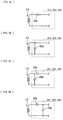
- FIGs. 5A to 5D and FIGs. 6A to 6C are circuit diagrams each illustrating a detailed configuration example of the above-described impedance matching circuits 211, 221, and 231.
- a capacitor C3s is connected in series with the common coil L2.
- a capacitor C3p is connected in parallel with the common coil L2.
- the capacitor C3s is connected in series with the common coil L2, and the capacitor C3p is connected in parallel with the common coil L2.
- transistors Tr3s and Tr3p for switching the connection state of the capacitor C3s or C3p are provided in the impedance matching circuits 211, 221, and 231.
- the transistor Tr3p for switching the connection state of the capacitor C3p is connected in series with the capacitor C3p.
- the example illustrated in FIG. 6A in the impedance matching circuits 211, 221, and 231 illustrated in FIG. 5C , the transistor Tr3p for switching the connection state of the capacitor C3p is connected in series with the capacitor C3p.
- capacitors C3s1 and C3s2 each are connected in series with the common coil L2, the capacitor C3p is connected in parallel with the common coil L2, and the capacitors C3s1 and C3s2 are connected in parallel with each other.
- the transistor Tr3s for switching the connection state of the capacitor C3s2 is connected in series with the capacitor C3s2.
- the transistor Tr3p for switching the connection state of the capacitor C3p is connected in series with the capacitor C3p.
- the transistor Tr3s for switching the connection state of the capacitor C3s is connected in parallel with the capacitor C3s.
- FIG. 7 is a circuit diagram illustrating the detailed configuration example of the above-described voltage detection sections 233, 233A, and 233B.
- each of the voltage detection sections 233, 233A, and 233B includes a rectification circuit 51, a threshold voltage output section 52, a comparator 53, and two resistors R51 and R52.
- the rectification circuit 51 is a circuit rectifying the signal S2 (an AC signal) input from the common coil L2 through the impedance matching circuit 231, and accordingly outputting a signal converted from the AC voltage to the DC voltage.
- the threshold voltage output section 52 outputs one of four threshold voltages Vth11, Vth12, Vth21, and Vth22 which will be described later to input terminal on the negative (-) side of the comparator 53.
- the threshold voltage output section 52 includes a predetermined power supply circuit and the like.
- Each of the resistors R51 and R52 is a resistor dividing a DC voltage output from the rectification circuit 51.
- a first end of the resistor R51 is connected to an output terminal of the rectification circuit 51, and a second end of the resistor R51 is connected to a first end of the resistor R52 and an input terminal on the positive (+) side of the comparator 53.
- a second end of the resistor R52 is grounded.
- the comparator 53 is a circuit comparing a magnitude of one of the detection voltages V(S2), V(S21), and V(S22) supplied to the input terminal on the positive side with a magnitude of one of the threshold voltages Vth11, Vth12, Vth21, and Vth22 supplied to the input terminal on the negative side. Accordingly, the above-described detection result signal J(S2), J(S21), or J(S22) (for example, a binary signal of "L (low)” or “H (high)” corresponding to the comparison result) as a comparison result is output from the output terminal of the comparator 53. Note that the detail of the comparison operation between the detection voltages V(S2), V(S21), and V(S22) and the threshold voltages Vth11, Vth12, Vth21, and Vth22 will be described later ( FIG. 10 ).
- the configuration of the voltage detection sections 233, 233A, and 233B is not limited to the configuration illustrated in FIG. 7 .
- a circuit configuration in which a predetermined digital processing is performed after the input signal S2 (an analog signal) is converted into a digital signal by an A/D (analog/digital) converter may be available.
- the power-transmission operation section 11 of the feed unit 1 supplies a predetermined high frequency power (AC signal) for performing power transmission to the common coil L1.
- a magnetic field magnetic flux
- the common coil L1 in the feed unit 1 and the common coil L2 of the electronic apparatuses 2A and 2B come close to each other near the feeding surface.
- the following charging operation is performed in the power-reception operation section 21, based on the power (AC power) received by the common coil L2.
- the charging section 212 the battery 213 is charged after the AC power is converted into a predetermined DC power, for example. In this way, in the electronic apparatuses 2A and 2B, the charging operation based on the power received by the common coil L2 is performed.
- terminal connection to the AC adaptor or the like is not necessary for charging the electronic apparatuses 2A and 2B, and charging is easily started (non-contact feeding is performed) by only placing (or closely disposing) the electronic apparatuses 2A and 2B on the feeding surface of the feed unit 1. This leads to liability relief of a user.
- non-contact mutual data transmission is performed between the data-transmission operation section 12 in the primary-side unit (the feed unit 1) and the data-transmission operation section 22 in the secondary-side unit (the electronic apparatuses 2A and 2B), with use of a magnetic field.
- the common coil L1 in the feed unit 1 and the common coil L2 in the electronic apparatuses 2A and 2B come close to each other, mutual data transmission with use of a magnetic field is performed.
- data transmission is allowed to be performed only by allowing the feed unit 1 and the electronic apparatuses 2A and 2B to come close to each other, without connecting wirings for data transmission between the feed unit 1 and the electronic apparatuses 2A and 2B.
- liability relief of a user is achievable in this point.
- control operation switching control operation of the changeover switches SW1 and SW2 by the switch control section 23 that is one of features of the embodiment will be described in detail with comparing to comparative examples (comparative examples 1 and 2).
- FIG. 8 illustrates a block configuration of a transmission system (a transmission system 104) according to a comparative example 1.
- the transmission system 104 of the comparative example 1 includes the feed unit 1 and two electronic apparatuses 102A and 102B.
- Each of the electronic apparatuses 102A and 102B includes the power-reception operation section 21, the data-transmission operation section 22, a power-reception coil L21, and a data-transmission coil L22.
- the power-reception coil L21 and the data-transmission coil L22 are separately provided.
- the power-reception coil L21 and the data-transmission coil L22 are separately provided in this way for the following reason. Transmission is basically performed in accordance with the same principle (with use of a magnetic field) in two non-contact transmission systems (power transmission system and data transmission system). However, the following two large different points are present between the systems.
- the applied power is largely different between the systems.
- the received power is a power necessary for driving an IC (integrated circuit) (about several mW to about several tens mW)
- the received power is about several W. Therefore, voltage resistance of the IC in the system is also largely different, and when a voltage equivalent to the voltage applied to the power transmission system is applied to the data transmission system, the circuit is possibly damaged by overvoltage.
- the applied frequency is largely different between the systems (the feed frequency f1 and the data-transmission frequency f2 are different from each other) as described with referring to (A) and (B) of FIG. 4 .
- the use of a carrier having the data-transmission frequency f2 of 13.56MHz is defined by international standard.
- a frequency is selected from the viewpoint of regulations, efficiency, and the like, due to large power in feeding.
- the frequency (the feed frequency f1) is high, loss in the circuit is increased and the degree of efficiency reduction (feed efficiency and the like) is possibly increased. Therefore, in the present circumstances, as the feed frequency f1, a frequency of around 120 kHz or around 6.78 MHz is supported by standardization associations.
- the power-reception coil L21 and the data-transmission coil L22 are separately provided as described above.
- the manufacturing cost and its mounting area are largely restricted. In other words, in the comparative example 1, it is difficult to achieve cost reduction and downsizing.
- a transmission system (a transmission system 204) according to a comparative example 2 illustrated in FIG. 9 includes the feed unit 1 and two electronic apparatuses 202A and 202B each including the common coil L2.
- the common coil L2 commonly used as the power-reception coil and the data-transmission coil is employed so that the number (kinds) of coils is reduced compared with the comparative example 1, and cost reduction and downsizing are achieved.
- Each of the electronic apparatuses 202A and 202B includes the power-reception operation section 21, the data-transmission operation section 22, the common coil L2, the changeover switches SW1 and SW2, and a switch control section 203.
- each of the electronic apparatuses 202A and 202B is configured by providing the switch control section 203 in the electronic apparatuses 2A and 2B of the embodiment, in place of the switch control section 23.
- the switch control section 203 includes the impedance matching circuit 231, the voltage detection section 233, and the control section 234.
- the switch control section 203 is configured by removing (not providing) the BPFs 232A and 232B and the voltage detection sections 233, 233A, and 233B from the switch control section 23. Therefore, the switch control section 203 generates and outputs the control signals CTL1 and CTL2, based on the detection result signal J(S2) (a detection result of the entire signal S2) by the voltage detection section 233, thereby performing the switching control of the changeover switches SW1 and SW2.
- the transmission system 204 of the comparative example 2 has disadvantages as follows.
- the switching control operation is performed only using the detection result of the entire signal S2. Therefore, for example, when the signal S2 having high signal level (voltage) is applied abruptly, there is a possibility that the circuit in the data-transmission operation section 22 is still in a valid state (the changeover switch SW2 is in the ON state). Therefore, when the data-transmission operation section 22 is in the valid state, if the mode is switched from the data transmission mode to the power transmission mode on the feed unit 1 side, the circuit in the data-transmission operation section 22 is possibly damaged by overvoltage.
- the switch control section 23 performs control operation (switching control operation) of the changeover switches SW1 and SW2 in the following manner.
- the switch control section 23 performs such switching control, based on the detection results with taking account of the frequency components of the signal S2 received by the common coil L2 from the outside (the feed unit 1).
- the switching control operation is performed not by using only the detection results of the entire signal S2 like in the comparative example 2, but by taking account of the frequency components of the signal S2.
- the switch control section 23 performs switching control based on the magnitude of the signal level of each of the frequency component for the power transmission and the frequency component for the data transmission in the signal S2. In addition, at this time, the switch control section 23 performs such switching control with use of a comparison result of the signal level of each of the frequency component for the power transmission and the frequency component for the data transmission (each component of the feed frequency f1 and the data-transmission frequency f2 in the signal S2) and predetermined threshold voltages Vth21 and Vth22 (carrier thresholds), as will be described later.
- the circuit (for example, the circuit in the data-transmission operation section 22) is prevented from being damaged by the difference between the system configuration at the time of the power transmission and the system configuration at the time of the data transmission.
- FIG. 10 is a flowchart illustrating an example of the switching control operation by the switch control section 23 of the embodiment.
- the voltage detection section 233 in the switch control section 23 detects the detection voltage V(S2) as the signal level of the entire signal S2 (step S101). Then, the voltage detection section 233 determines whether the detection voltage V(S2) is larger than the predetermined threshold voltage Vth11 (a first entire threshold) (V(S2)>Vth11), or the voltage detection section 233 compares the magnitudes of the voltage values (step S102).
- step S102 when the detection voltage V(S2) is larger than the threshold voltage Vth11 (V(S2)>Vth11) (step S102: Y), the control section 234 performs a predetermined error processing, based on the detection result signal J(S2) indicating the determination result (step S103). Specifically, in this case, the control section 234 determines that a high voltage not performing the power transmission and the data transmission is applied, and controls the process to be returned to a first process (step S101) without performing switching control described below.
- the voltage detection sections 233A and 233B each then detect the signal level of the frequency components of the signal S2 (step S104). Specifically, the voltage detection section 233A detects the detection voltage V(S21) as a signal level of the component (signal S21) of the feed frequency f1 in the signal S2. In addition, the voltage detection section 233B detects the detection voltage V(S22) as a signal level of the component (signal S22) of the data-transmission frequency f2 in the signal S2.
- the voltage detection section 233A determines whether the detection voltage V(S21) is equal to or larger than the predetermined threshold voltage Vth21 (the first carrier threshold) (V(S21) ⁇ Vth21), or the voltage detection section 233A compares the magnitudes of the voltage values (step S105).
- the switch control section 23 performs comparison between the detection voltage V(S21) and the threshold voltage Vth21 (step S105) and switching control of the changeover switches SW1 and SW2, which will be described below. Accordingly, the circuits and the like in the power-reception operation section 21 and the data transmission section 22 are prevented from being damaged by the abrupt high voltage application.
- step S105: Y when the detection voltage V(S21) is equal to or larger than the threshold voltage Vth21 (V(S21) ⁇ Vth21) (step S105: Y), the control section 234 outputs the control signal CTL1 to allow the changeover switch SW1 to be in the ON state, based on the detection result signal J(S21) indicating the determination result. Accordingly, a period during which the changeover switch SW1 is in the ON state is established, that is, the mode is changed into the power transmission mode (feeding mode) in which the operation of the power-reception operation section 21 is in the valid state (step S106). After that, the process returns to the first process (step S101).
- step S105 when the detection voltage V(S21) is smaller than the threshold voltage Vth21 (V(S21) ⁇ Vth2 ) (step S105: N), the control section 234 outputs the control signal CTL1 to allow the changeover switch SW1 to be in the OFF state (step S107). Then, the voltage detection section 233B determines whether the detection voltage V(S22) is equal to or larger than the predetermined threshold voltage Vth22 (the second carrier threshold) (V(S22) ⁇ Vth22), or the detection voltage section 233B compares the magnitudes of the voltage values (step S108).
- the voltage detection section 233 performs comparison of the magnitudes of the voltage values described below. Specifically, the voltage detection section 233 determines whether the detection voltage V(S2) is larger than the predetermined threshold voltage Vth12 (a second entire threshold) (V(S2)>Vthl2) (step S109). Note that the threshold voltage Vth12 is smaller than the above-described threshold voltage Vth11, in other words, the threshold voltage Vth11 is larger than the threshold voltage Vth12 (Vth12 ⁇ Vth11).
- step S108: N when the detection voltage V(S22) is smaller than the threshold voltage Vth22 (V(S22) ⁇ Vth22) (step S108: N), the control section 234 outputs the control signal CTL2 to allow the changeover switch SW2 to be in the OFF state, based on the detection result signal J(S22) indicating the determination result (step S110).
- step S109: Y when the detection voltage V(S2) is larger than the threshold voltage Vth12 (V(S2)>Vth12) (step S109: Y), the control section 234 outputs the control signal CTL2 to allow the changeover switch SW2 to be in the OFF state, based on the detection result signal J(S2) indicating the determination result (step S110).
- step S109: N when the detection voltage V(S2) is equal to or smaller than the threshold voltage Vth12 (V(S2) ⁇ Vth12) (step S109: N), the control section 234 outputs the control signal CTL2 to allow the changeover switch SW2 to be in the ON state.
- step S111 a period during which the changeover switch SW2 is in the ON state is established, that is, the mode is changed into the data transmission mode (communication mode) in which the operation of the data-transmission operation section 22 is in the valid state. After that, the process returns to the first process (step S101).
- the switch control section 23 controls the changeover switch SW2 to be in the ON state. Accordingly, the circuit (the circuit in the data-transmission operation section, and the like) is prevented from being damaged by the difference between the system configuration (configuration of the power-reception operation section 21) at the time of the power transmission and the system configuration (configuration of the data-transmission operation section 22) at the time of data transmission.
- step S 112 whether the entire control processing (switching control operation) by the switch control section 23 is allowed to be ended is determined. Then, when it is determined that the control processing is allowed not to be ended (step S 112: N), the process returns to the first process (step S101), and when it is determined that the control processing is allowed to be ended (step S112: Y), the entire control processing illustrated in FIG. 10 is ended.
- the power transmitted through the power transmission with use of a magnetic field is received, and the mutual data transmission with use of a magnetic field is performed.
- the number (kinds) of coils is allowed to be reduced, compared with the case where these operations are performed with use of the dedicated coils (the power reception coil L21 and the data transmission coil L22) like the above-described comparative example 1.
- the switching control of ON/OFF state of each of the changeover switch SW1 on the path between the common coil L2 and the power-reception operation section 21 and the changeover switch SW2 on the path between the common coil L2 and the data-transmission operation section 22 is performed based on the detection results with taking account of the frequency components of the signal S2 received by the common coil L2 from the outside (the feed unit 1).
- the circuit unlike the above-described comparative example 2, the circuit (the circuit in the data-transmission operation section 22, and the like) is prevented from being damaged by the difference between the system configuration at the time of the power transmission and the system configuration at the time of the data transmission.
- the switching control is performed to allow the changeover switch SW2 to be in the OFF state.
- the switching control of the ON/OFF state of the changeover switch SW1 on the path between the common coil L2 and the power-reception operation section 21 and the changeover switch SW2 on the path between the common coil L2 and the data-transmission operation section 22 is performed based on the detection results with taking account of the frequency components of the signal S2 received by the common coil L2 from the outside (the feed unit 1).
- the circuit is prevented from being damaged by the difference between the system configuration at the time of the power transmission and the system configuration at the time of the data transmission, thereby improving safety. Consequently, at the time of performing the power transmission and the data transmission with use of a magnetic field, safety is allowed to be improved while cost reduction and downsizing are achieved.
- the value of the feed frequency f1 is allowed to be selectable, and the circuit in each of the power transmission system and the data transmission system is allowed to use the existing IC as it is (change of the design or the like is not necessary).
- each coil is allowed to be configured in shapes such as a spiral shape, a loop shape, a bar shape using a magnetic body, an alpha-wound shape configured by folding a spiral coil into two layers, a multilayer spiral shape, a helical shape configured by winding a wire in a thickness direction thereof.
- each coil is not limited to a winding coil configured of a conductive wire rod, and may be a conductive patterned coil configured of a printed board, a flexible printed board, or the like.
- the electronic apparatus has been described as an example of a unit to be fed with power
- the unit to be fed with power is not limited thereto, and may be other than the electronic apparatus (for example, vehicles such as electric cars).
- each of the feed unit and the electronic apparatuses has been specifically described. However, all of the components are not necessarily provided, and other components may be further provided.
- a communication function, a control function, a display function, a function of authenticating a secondary-side unit, a function of determining whether a secondary-side unit is placed on a primary-side unit, a function of detecting a contaminant such as a dissimilar metal, and the like may be provided.
- a single common coil like in the above-described embodiment is not provided, but a power transmission coil and a data transmission coil may be provided separately.
- the transmission system includes a plurality of (two) electronic apparatuses has been described as an example.
- the number of electronic apparatuses is not limited thereto, and the transmission system may include only one electronic apparatus.
- the charging tray for a small electronic apparatus such as a mobile phone
- the feed unit is not limited to such a household charging tray, and is applicable as a charging unit for various electronic apparatuses, and the like.
- the feed unit is not necessarily a tray, and may be a stand for electronic apparatuses such as a so-called cradle.
- an electronic apparatus includes a switch control section configured to: determine whether a received signal is any one of a power signal and a data signal based on the received signal, and select any one of a power-reception operation and a data-transmission operation based on the determination of the received signal.
- the electronic apparatus further includes a coil electrically connected to the switch control section thereby allowing selection of any one of the power-reception operation and the data-transmission operation.
- the coil is configured to be electromagnetically coupled to a second coil of a feed unit to wirelessly receive any one of the power signal and the data signal from the feed unit.
- the electronic apparatus includes a mobile electronic apparatus and the battery is a rechargeable battery.
- the data-transmission operation is configured to transmit signals generated by a signal supply source.
- the switch control section includes: a first filter configured to filter the received signal associated with a first frequency component; a first voltage detection circuit configured to determine if the first frequency component exceeds a first voltage threshold; a second filter configured to filter the received signal associated with a second frequency component; and a second voltage detection circuit configured to determine if the second frequency component exceeds a second voltage threshold, and wherein the switch control section is configured to determine that the received signal is to be transmitted to: a power-reception operation section if the first voltage detection circuit determines the first frequency component exceeds the first voltage threshold; and a data-transmission operation section if the second voltage detection circuit determines the second frequency component exceeds the second voltage threshold.
- the electronic apparatus further includes a third voltage detection circuit configures to determine if the received signal exceeds a third voltage threshold.
- the switch control section performs error processing if the third voltage detection circuit determines the received signal exceeds the third voltage threshold.
- error processing includes the control section refraining from transmitting the received wireless signal to any one of the power-reception operation section and the data-transmission operation section.
- the first voltage detection circuit includes: a first rectification circuit to convert the first frequency component into a first direct current signal; and a first comparator to determine if a magnitude first direct current signal exceeds a magnitude of the first voltage threshold; and the second voltage detection circuit includes: a second rectification circuit to convert the second frequency component into a second direct current signal; and a second comparator to determine if a magnitude the second direct current signal exceeds a magnitude the second voltage threshold.
- the switch control section is configured to: transmit a first control signal to a first switch causing the first switch to route the received signal to the power-reception operation section if the first frequency component exceeds the first voltage threshold; and transmit a second control signal to a second switch causing the second switch to route the received signal to the data-transmission operation section if the second frequency component exceeds the second voltage threshold.
- the switch control section is configured to be prevented from outputting the first control signal simultaneously with the second control signal.
- the first filter is configured to filter the received signal for frequencies substantially around 120 kilohertz (kHz) or 6.78 megahertz (MHz).
- the first filter is configured to be selectable between frequencies substantially around 120 kilohertz (kHz) or 6.78 megahertz (MHz).
- the second filter is configured to filter the received signal for frequencies substantially around 13.56 megahertz (MHz).
- the switch control section is configured to perform switching control by selecting any one of a power-reception operation and a data-transmission operation based on a magnitude of a signal level of the received signal of each of a frequency component for the power transmission and a frequency component for the data transmission in the signal.
- the switch control section performs the switching control with use of comparison results between a predetermined carrier threshold and the signal level of each of the frequency component for the power transmission and the frequency component for the data transmission.
- the switch control section controls a first changeover switch to be in the ON state when the signal level of the frequency component for the power transmission is equal to or larger than a first carrier threshold, and controls the first changeover switch to be in the OFF state when the signal level of the frequency component for the power transmission is smaller than the first carrier threshold.
- a method of routing a received wireless signal based on a frequency includes: receiving a signal wirelessly from a feed unit via magnetic inductance; applying a first filter to the received signal to generate a first frequency component; applying a second filter to the received signal to generate a second frequency component; routing the received signal to a power-reception operation section if a magnitude of the first frequency component exceeds a first voltage threshold; and routing the received signal to a data-transmission operation section if a magnitude of the second frequency component exceeds a second voltage threshold.
- the method further includes: determining whether the received signal is greater than a third voltage threshold prior to routing the received signal; and performing error processing on the received signal if the received signal is greater than the third voltage threshold.
- error processing includes routing the received signal to a ground potential instead of routing the received signal to the data-transmission operation section or the power-reception operation section.
- the received signal and subsequent received signals are routed to the power-reception operation section so long as a magnitude of the first frequency component of the subsequent received signals exceeds the first voltage threshold.
- the received signal and subsequent received signals are routed to the data-transmission operation section so long as a magnitude of the second frequency component of the subsequent received signals exceeds the second voltage threshold and a magnitude of the first frequency component of the subsequent received signals is less than the first voltage threshold.
- an electronic system in another embodiment, includes: a transmitter configured to wirelessly transmit a power signal and a data signal; an electronic device wirelessly communicatively coupled to the transmitter, the electronic device including: a switch control section to: determine whether a signal received from the transmitter is the power signal or the data signal based on a frequency component of the received signal; and select any one of a power-reception operation and a data-transmission operation based on the determination of the received signal.
- the electronic device includes an induction coil that is electromagnetically coupled to a second induction coil included within the transmitter.
- the transmitter is a charging tray.
- the transmitter includes a detection circuit configured to detect a second data signal from the electronic device. In an embodiment, the transmitter suspends transmitting the power signal when the detection circuit detects the second data signal.
Landscapes
- Engineering & Computer Science (AREA)
- Power Engineering (AREA)
- Computer Networks & Wireless Communication (AREA)
- Signal Processing (AREA)
- Charge And Discharge Circuits For Batteries Or The Like (AREA)
- Near-Field Transmission Systems (AREA)
- Transmitters (AREA)
Applications Claiming Priority (3)
| Application Number | Priority Date | Filing Date | Title |
|---|---|---|---|
| JP2011244320A JP5821544B2 (ja) | 2011-11-08 | 2011-11-08 | 電子機器および伝送システム |
| PCT/JP2012/077667 WO2013069472A2 (en) | 2011-11-08 | 2012-10-19 | Electronic apparatus and transmission system |
| JP2015197314A JP6044692B2 (ja) | 2011-11-08 | 2015-10-05 | 制御装置、受電装置および伝送システム |
Publications (2)
| Publication Number | Publication Date |
|---|---|
| EP2777128A2 EP2777128A2 (en) | 2014-09-17 |
| EP2777128B1 true EP2777128B1 (en) | 2016-05-11 |
Family
ID=59383689
Family Applications (1)
| Application Number | Title | Priority Date | Filing Date |
|---|---|---|---|
| EP12821066.3A Active EP2777128B1 (en) | 2011-11-08 | 2012-10-19 | Electronic apparatus and transmission system |
Country Status (8)
| Country | Link |
|---|---|
| US (2) | US9847814B2 (zh) |
| EP (1) | EP2777128B1 (zh) |
| JP (2) | JP5821544B2 (zh) |
| KR (1) | KR101970849B1 (zh) |
| CN (1) | CN104025415B (zh) |
| BR (1) | BR112014010498A2 (zh) |
| TW (1) | TWI470899B (zh) |
| WO (1) | WO2013069472A2 (zh) |
Cited By (2)
| Publication number | Priority date | Publication date | Assignee | Title |
|---|---|---|---|---|
| US11757490B2 (en) | 2018-08-02 | 2023-09-12 | Fraunhofer-Gesellschaft zur Förderung der angewandten Forschung e.V | Data transmission from a user terminal to another apparatus |
| US12096167B2 (en) | 2019-01-30 | 2024-09-17 | Fraunhofer-Gesellschaft Zur Foerderung Der Angewandten Forschung E.V. | Bidirectional configuration of sensor nodes with mobile phone with no extension |
Families Citing this family (27)
| Publication number | Priority date | Publication date | Assignee | Title |
|---|---|---|---|---|
| JP5821544B2 (ja) | 2011-11-08 | 2015-11-24 | ソニー株式会社 | 電子機器および伝送システム |
| US9246357B2 (en) | 2011-12-07 | 2016-01-26 | Semiconductor Energy Laboratory Co., Ltd. | Contactless power feeding system |
| JP6045150B2 (ja) * | 2011-12-27 | 2016-12-14 | Necトーキン株式会社 | 電子機器、モジュール及びシステム |
| US9762080B2 (en) * | 2013-06-24 | 2017-09-12 | Htc Corporation | Electronic apparatus, system and charging method thereof |
| TWI506912B (zh) * | 2013-08-02 | 2015-11-01 | Simplo Technology Co Ltd | 無線電力傳遞管理系統及其方法 |
| KR20150021285A (ko) | 2013-08-20 | 2015-03-02 | 엘지이노텍 주식회사 | 무선전력 수신장치 |
| JP6010014B2 (ja) * | 2013-12-13 | 2016-10-19 | 株式会社東芝 | 通信制御装置 |
| KR101943082B1 (ko) * | 2014-01-23 | 2019-04-18 | 한국전자통신연구원 | 무선 전력 송신 장치, 무선 전력 수신 장치, 및 무선 전력 전송 시스템 |
| JP6233780B2 (ja) * | 2014-01-31 | 2017-11-22 | アルプス電気株式会社 | 無線電力伝送システム |
| WO2015158482A1 (en) * | 2014-04-14 | 2015-10-22 | Philip Morris Products S.A. | Power and data transmission system and method |
| JP2015220816A (ja) * | 2014-05-15 | 2015-12-07 | Necトーキン株式会社 | 非接触信号伝送装置、及び非接触電力受電装置 |
| US9818005B2 (en) | 2014-06-13 | 2017-11-14 | Verily Life Sciences Llc | Zero-power wireless device programming |
| US20170250562A1 (en) * | 2014-10-01 | 2017-08-31 | Humavox, Ltd. | Combined RF Charging And Communication Module and Methods of Use |
| US20160126639A1 (en) * | 2014-10-14 | 2016-05-05 | Samsung Electro-Mechanics Co., Ltd. | Coil structure and wireless power receiving apparatus including the same |
| KR20160046187A (ko) * | 2014-10-20 | 2016-04-28 | 삼성전자주식회사 | 안테나 구조 및 그 안테나 구조를 갖는 전자 장치 |
| KR102400578B1 (ko) * | 2016-03-21 | 2022-05-20 | 주식회사 위츠 | 무선 신호 수신 장치 및 그의 제어 방법 |
| US10355535B2 (en) * | 2016-04-01 | 2019-07-16 | Electrolux Home Products, Inc. | Appliance for wireless power and data transfer |
| DE202016101808U1 (de) * | 2016-04-06 | 2016-04-27 | Fraunhofer-Gesellschaft zur Förderung der angewandten Forschung e.V. | System zur drahtlosen Übertragung von Energie und Daten |
| CN107689690A (zh) * | 2016-07-29 | 2018-02-13 | 施京京 | 一种用于移动设备的无线连接装置 |
| TWI609548B (zh) * | 2016-08-19 | 2017-12-21 | Newvastek Co Ltd | Wireless charger protection device |
| CN107959358B (zh) * | 2016-10-17 | 2020-05-05 | 宁波微鹅电子科技有限公司 | 一种无线充电装置的控制方法及无线充电装置 |
| US10277061B1 (en) * | 2018-03-08 | 2019-04-30 | Nxp B.V. | Wireless device |
| EP3681005A1 (en) * | 2019-01-08 | 2020-07-15 | Energysquare | Reporting device for multimodal article interface |
| TWM593417U (zh) | 2019-11-26 | 2020-04-11 | 緯創資通股份有限公司 | 基因擴增設備 |
| CN111651387B (zh) * | 2020-05-25 | 2022-02-15 | 维沃移动通信有限公司 | 接口电路与电子设备 |
| CN111641437B (zh) * | 2020-05-28 | 2021-06-18 | Oppo(重庆)智能科技有限公司 | 近场通信与无线充电天线模组及电子装置 |
| US12042043B2 (en) | 2020-06-11 | 2024-07-23 | Kohler Co. | Temperature tracking mirror |
Family Cites Families (22)
| Publication number | Priority date | Publication date | Assignee | Title |
|---|---|---|---|---|
| JPS61101886A (ja) | 1984-10-24 | 1986-05-20 | Tdk Corp | Icカ−ド結合方式 |
| US4641126A (en) * | 1984-12-07 | 1987-02-03 | Ferranti-Subsea Systems, Ltd. | Multiple-mode electrical power and communications interface |
| JPH1166031A (ja) * | 1997-08-11 | 1999-03-09 | Mitsubishi Electric Corp | マイクロコンピュータの内蔵タイマ |
| US6737984B1 (en) * | 1997-08-15 | 2004-05-18 | General Electric Company | Automatic meter reading system using locally communicating utility meters |
| TW463399B (en) * | 1999-03-19 | 2001-11-11 | Seiko Epson Corp | Electronic device |
| DE10019539A1 (de) * | 2000-04-20 | 2001-10-25 | Abb Research Ltd | Sensor mit drahtloser Energieversorgung |
| JP2003198400A (ja) * | 2001-12-26 | 2003-07-11 | Sharp Corp | Rf受信器及び無線通信装置 |
| JP2005202721A (ja) | 2004-01-16 | 2005-07-28 | Matsushita Electric Ind Co Ltd | 非接触データキャリア |
| JP2006246595A (ja) * | 2005-03-02 | 2006-09-14 | Sanyo Electric Co Ltd | 二次電池装置 |
| DE102006035007A1 (de) * | 2006-07-28 | 2008-01-31 | Siemens Audiologische Technik Gmbh | Hörhilfe mit einem Radiofrequenzidentifikations-Empfänger zum Schalten einer Übertragungseigenschaft |
| JP4847891B2 (ja) | 2007-02-20 | 2011-12-28 | ソニー・エリクソン・モバイルコミュニケーションズ株式会社 | 携帯電子機器 |
| US20090322285A1 (en) | 2008-06-25 | 2009-12-31 | Nokia Corporation | Method and Apparatus for Wireless Charging Using a Multi-Band Antenna |
| EP2367262B1 (en) * | 2008-12-12 | 2019-02-27 | GE Hybrid Technologies, LLC | Contactless power receiving device |
| JP2010284065A (ja) | 2009-06-08 | 2010-12-16 | Nec Tokin Corp | 電力・信号伝送モジュール、非接触充電モジュールならびに非接触充電および信号伝送システム |
| JP2011029799A (ja) * | 2009-07-23 | 2011-02-10 | Sony Corp | 非接触給電通信装置、非接触受電通信装置、給電通信制御方法および受電通信制御方法 |
| JP5174769B2 (ja) * | 2009-09-11 | 2013-04-03 | 三菱電機株式会社 | 非接触伝送装置 |
| JP5463932B2 (ja) | 2010-01-26 | 2014-04-09 | ソニー株式会社 | 情報処理装置、情報処理方法および情報処理システム |
| JP5551465B2 (ja) | 2010-02-16 | 2014-07-16 | Necトーキン株式会社 | 非接触電力伝送及び通信システム |
| US8791665B2 (en) * | 2010-04-08 | 2014-07-29 | Qualcomm Incorporated | Energy storage device security |
| US8983374B2 (en) * | 2010-12-13 | 2015-03-17 | Qualcomm Incorporated | Receiver for near field communication and wireless power functionalities |
| US9281689B2 (en) * | 2011-06-08 | 2016-03-08 | General Electric Technology Gmbh | Load phase balancing at multiple tiers of a multi-tier hierarchical intelligent power distribution grid |
| JP5821544B2 (ja) * | 2011-11-08 | 2015-11-24 | ソニー株式会社 | 電子機器および伝送システム |
-
2011
- 2011-11-08 JP JP2011244320A patent/JP5821544B2/ja not_active Expired - Fee Related
-
2012
- 2012-10-08 TW TW101137136A patent/TWI470899B/zh active
- 2012-10-19 CN CN201280053944.4A patent/CN104025415B/zh active Active
- 2012-10-19 WO PCT/JP2012/077667 patent/WO2013069472A2/en active Application Filing
- 2012-10-19 KR KR1020147010991A patent/KR101970849B1/ko active IP Right Grant
- 2012-10-19 BR BR112014010498A patent/BR112014010498A2/pt not_active Application Discontinuation
- 2012-10-19 US US14/355,150 patent/US9847814B2/en not_active Expired - Fee Related
- 2012-10-19 EP EP12821066.3A patent/EP2777128B1/en active Active
-
2015
- 2015-10-05 JP JP2015197314A patent/JP6044692B2/ja not_active Expired - Fee Related
-
2017
- 2017-11-28 US US15/824,295 patent/US10567040B2/en active Active
Cited By (2)
| Publication number | Priority date | Publication date | Assignee | Title |
|---|---|---|---|---|
| US11757490B2 (en) | 2018-08-02 | 2023-09-12 | Fraunhofer-Gesellschaft zur Förderung der angewandten Forschung e.V | Data transmission from a user terminal to another apparatus |
| US12096167B2 (en) | 2019-01-30 | 2024-09-17 | Fraunhofer-Gesellschaft Zur Foerderung Der Angewandten Forschung E.V. | Bidirectional configuration of sensor nodes with mobile phone with no extension |
Also Published As
| Publication number | Publication date |
|---|---|
| CN104025415A (zh) | 2014-09-03 |
| WO2013069472A2 (en) | 2013-05-16 |
| WO2013069472A3 (en) | 2013-07-18 |
| TW201334356A (zh) | 2013-08-16 |
| TWI470899B (zh) | 2015-01-21 |
| US10567040B2 (en) | 2020-02-18 |
| JP6044692B2 (ja) | 2016-12-14 |
| US20140312709A1 (en) | 2014-10-23 |
| BR112014010498A2 (pt) | 2017-04-25 |
| CN104025415B (zh) | 2017-05-24 |
| KR101970849B1 (ko) | 2019-04-19 |
| JP2013102594A (ja) | 2013-05-23 |
| JP5821544B2 (ja) | 2015-11-24 |
| JP2016013055A (ja) | 2016-01-21 |
| KR20140089355A (ko) | 2014-07-14 |
| US9847814B2 (en) | 2017-12-19 |
| US20180083670A1 (en) | 2018-03-22 |
| EP2777128A2 (en) | 2014-09-17 |
Similar Documents
| Publication | Publication Date | Title |
|---|---|---|
| EP2777128B1 (en) | Electronic apparatus and transmission system | |
| JP6298509B2 (ja) | 無線電力受信方法 | |
| US10153666B2 (en) | Wireless power receiver and control method thereof | |
| US9954397B2 (en) | Feed unit including power transmission coil and feed system | |
| JP6918069B2 (ja) | 受電装置 | |
| WO2015115285A1 (ja) | 受電装置、受電制御方法、非接触給電システム、および電子機器 | |
| CN108475936B (zh) | 非接触输电装置 | |
| JP6465247B2 (ja) | アンテナ装置および電子機器 | |
| WO2015099065A1 (ja) | 非接触受電回路、非接触受電装置及び非接触送受電装置 | |
| CN110612652B (zh) | 近场通信和接近检测设备 | |
| EP2902252B1 (en) | Non-contact electric power transmission system and charging station | |
| JP2014217116A (ja) | 電子機器、電子機器送電システム及び受電制御方法 | |
| CN110521081B (zh) | 使用非谐振电能接收器的无线电能传输系统和方法 |
Legal Events
| Date | Code | Title | Description |
|---|---|---|---|
| PUAI | Public reference made under article 153(3) epc to a published international application that has entered the european phase |
Free format text: ORIGINAL CODE: 0009012 |
|
| 17P | Request for examination filed |
Effective date: 20140430 |
|
| AK | Designated contracting states |
Kind code of ref document: A2 Designated state(s): AL AT BE BG CH CY CZ DE DK EE ES FI FR GB GR HR HU IE IS IT LI LT LU LV MC MK MT NL NO PL PT RO RS SE SI SK SM TR |
|
| DAX | Request for extension of the european patent (deleted) | ||
| 17Q | First examination report despatched |
Effective date: 20150629 |
|
| GRAP | Despatch of communication of intention to grant a patent |
Free format text: ORIGINAL CODE: EPIDOSNIGR1 |
|
| INTG | Intention to grant announced |
Effective date: 20151118 |
|
| RIN1 | Information on inventor provided before grant (corrected) |
Inventor name: FUKUDA, SHINICHI Inventor name: NAKANO, HIROAKI Inventor name: FUJIMAKI, KENICHI Inventor name: KOZAKAI, OSAMU |
|
| GRAS | Grant fee paid |
Free format text: ORIGINAL CODE: EPIDOSNIGR3 |
|
| GRAA | (expected) grant |
Free format text: ORIGINAL CODE: 0009210 |
|
| AK | Designated contracting states |
Kind code of ref document: B1 Designated state(s): AL AT BE BG CH CY CZ DE DK EE ES FI FR GB GR HR HU IE IS IT LI LT LU LV MC MK MT NL NO PL PT RO RS SE SI SK SM TR |
|
| REG | Reference to a national code |
Ref country code: GB Ref legal event code: FG4D |
|
| REG | Reference to a national code |
Ref country code: CH Ref legal event code: EP |
|
| REG | Reference to a national code |
Ref country code: AT Ref legal event code: REF Ref document number: 799348 Country of ref document: AT Kind code of ref document: T Effective date: 20160515 |
|
| REG | Reference to a national code |
Ref country code: IE Ref legal event code: FG4D |
|
| REG | Reference to a national code |
Ref country code: DE Ref legal event code: R096 Ref document number: 602012018400 Country of ref document: DE |
|
| REG | Reference to a national code |
Ref country code: LT Ref legal event code: MG4D |
|
| REG | Reference to a national code |
Ref country code: NL Ref legal event code: MP Effective date: 20160511 |
|
| PG25 | Lapsed in a contracting state [announced via postgrant information from national office to epo] |
Ref country code: NO Free format text: LAPSE BECAUSE OF FAILURE TO SUBMIT A TRANSLATION OF THE DESCRIPTION OR TO PAY THE FEE WITHIN THE PRESCRIBED TIME-LIMIT Effective date: 20160811 Ref country code: LT Free format text: LAPSE BECAUSE OF FAILURE TO SUBMIT A TRANSLATION OF THE DESCRIPTION OR TO PAY THE FEE WITHIN THE PRESCRIBED TIME-LIMIT Effective date: 20160511 Ref country code: FI Free format text: LAPSE BECAUSE OF FAILURE TO SUBMIT A TRANSLATION OF THE DESCRIPTION OR TO PAY THE FEE WITHIN THE PRESCRIBED TIME-LIMIT Effective date: 20160511 Ref country code: NL Free format text: LAPSE BECAUSE OF FAILURE TO SUBMIT A TRANSLATION OF THE DESCRIPTION OR TO PAY THE FEE WITHIN THE PRESCRIBED TIME-LIMIT Effective date: 20160511 |
|
| REG | Reference to a national code |
Ref country code: AT Ref legal event code: MK05 Ref document number: 799348 Country of ref document: AT Kind code of ref document: T Effective date: 20160511 |
|
| PG25 | Lapsed in a contracting state [announced via postgrant information from national office to epo] |
Ref country code: ES Free format text: LAPSE BECAUSE OF FAILURE TO SUBMIT A TRANSLATION OF THE DESCRIPTION OR TO PAY THE FEE WITHIN THE PRESCRIBED TIME-LIMIT Effective date: 20160511 Ref country code: RS Free format text: LAPSE BECAUSE OF FAILURE TO SUBMIT A TRANSLATION OF THE DESCRIPTION OR TO PAY THE FEE WITHIN THE PRESCRIBED TIME-LIMIT Effective date: 20160511 Ref country code: PT Free format text: LAPSE BECAUSE OF FAILURE TO SUBMIT A TRANSLATION OF THE DESCRIPTION OR TO PAY THE FEE WITHIN THE PRESCRIBED TIME-LIMIT Effective date: 20160912 Ref country code: LV Free format text: LAPSE BECAUSE OF FAILURE TO SUBMIT A TRANSLATION OF THE DESCRIPTION OR TO PAY THE FEE WITHIN THE PRESCRIBED TIME-LIMIT Effective date: 20160511 Ref country code: GR Free format text: LAPSE BECAUSE OF FAILURE TO SUBMIT A TRANSLATION OF THE DESCRIPTION OR TO PAY THE FEE WITHIN THE PRESCRIBED TIME-LIMIT Effective date: 20160812 Ref country code: HR Free format text: LAPSE BECAUSE OF FAILURE TO SUBMIT A TRANSLATION OF THE DESCRIPTION OR TO PAY THE FEE WITHIN THE PRESCRIBED TIME-LIMIT Effective date: 20160511 Ref country code: SE Free format text: LAPSE BECAUSE OF FAILURE TO SUBMIT A TRANSLATION OF THE DESCRIPTION OR TO PAY THE FEE WITHIN THE PRESCRIBED TIME-LIMIT Effective date: 20160511 |
|
| PG25 | Lapsed in a contracting state [announced via postgrant information from national office to epo] |
Ref country code: IT Free format text: LAPSE BECAUSE OF FAILURE TO SUBMIT A TRANSLATION OF THE DESCRIPTION OR TO PAY THE FEE WITHIN THE PRESCRIBED TIME-LIMIT Effective date: 20160511 |
|
| PG25 | Lapsed in a contracting state [announced via postgrant information from national office to epo] |
Ref country code: SK Free format text: LAPSE BECAUSE OF FAILURE TO SUBMIT A TRANSLATION OF THE DESCRIPTION OR TO PAY THE FEE WITHIN THE PRESCRIBED TIME-LIMIT Effective date: 20160511 Ref country code: CZ Free format text: LAPSE BECAUSE OF FAILURE TO SUBMIT A TRANSLATION OF THE DESCRIPTION OR TO PAY THE FEE WITHIN THE PRESCRIBED TIME-LIMIT Effective date: 20160511 Ref country code: EE Free format text: LAPSE BECAUSE OF FAILURE TO SUBMIT A TRANSLATION OF THE DESCRIPTION OR TO PAY THE FEE WITHIN THE PRESCRIBED TIME-LIMIT Effective date: 20160511 Ref country code: RO Free format text: LAPSE BECAUSE OF FAILURE TO SUBMIT A TRANSLATION OF THE DESCRIPTION OR TO PAY THE FEE WITHIN THE PRESCRIBED TIME-LIMIT Effective date: 20160511 Ref country code: DK Free format text: LAPSE BECAUSE OF FAILURE TO SUBMIT A TRANSLATION OF THE DESCRIPTION OR TO PAY THE FEE WITHIN THE PRESCRIBED TIME-LIMIT Effective date: 20160511 |
|
| REG | Reference to a national code |
Ref country code: DE Ref legal event code: R097 Ref document number: 602012018400 Country of ref document: DE |
|
| PG25 | Lapsed in a contracting state [announced via postgrant information from national office to epo] |
Ref country code: PL Free format text: LAPSE BECAUSE OF FAILURE TO SUBMIT A TRANSLATION OF THE DESCRIPTION OR TO PAY THE FEE WITHIN THE PRESCRIBED TIME-LIMIT Effective date: 20160511 Ref country code: SM Free format text: LAPSE BECAUSE OF FAILURE TO SUBMIT A TRANSLATION OF THE DESCRIPTION OR TO PAY THE FEE WITHIN THE PRESCRIBED TIME-LIMIT Effective date: 20160511 Ref country code: BE Free format text: LAPSE BECAUSE OF FAILURE TO SUBMIT A TRANSLATION OF THE DESCRIPTION OR TO PAY THE FEE WITHIN THE PRESCRIBED TIME-LIMIT Effective date: 20160511 Ref country code: AT Free format text: LAPSE BECAUSE OF FAILURE TO SUBMIT A TRANSLATION OF THE DESCRIPTION OR TO PAY THE FEE WITHIN THE PRESCRIBED TIME-LIMIT Effective date: 20160511 |
|
| PLBE | No opposition filed within time limit |
Free format text: ORIGINAL CODE: 0009261 |
|
| STAA | Information on the status of an ep patent application or granted ep patent |
Free format text: STATUS: NO OPPOSITION FILED WITHIN TIME LIMIT |
|
| 26N | No opposition filed |
Effective date: 20170214 |
|
| PG25 | Lapsed in a contracting state [announced via postgrant information from national office to epo] |
Ref country code: SI Free format text: LAPSE BECAUSE OF FAILURE TO SUBMIT A TRANSLATION OF THE DESCRIPTION OR TO PAY THE FEE WITHIN THE PRESCRIBED TIME-LIMIT Effective date: 20160511 |
|
| REG | Reference to a national code |
Ref country code: CH Ref legal event code: PL |
|
| GBPC | Gb: european patent ceased through non-payment of renewal fee |
Effective date: 20161019 |
|
| PG25 | Lapsed in a contracting state [announced via postgrant information from national office to epo] |
Ref country code: MC Free format text: LAPSE BECAUSE OF FAILURE TO SUBMIT A TRANSLATION OF THE DESCRIPTION OR TO PAY THE FEE WITHIN THE PRESCRIBED TIME-LIMIT Effective date: 20160511 |
|
| REG | Reference to a national code |
Ref country code: IE Ref legal event code: MM4A |
|
| REG | Reference to a national code |
Ref country code: FR Ref legal event code: ST Effective date: 20170630 |
|
| PG25 | Lapsed in a contracting state [announced via postgrant information from national office to epo] |
Ref country code: GB Free format text: LAPSE BECAUSE OF NON-PAYMENT OF DUE FEES Effective date: 20161019 Ref country code: CH Free format text: LAPSE BECAUSE OF NON-PAYMENT OF DUE FEES Effective date: 20161031 Ref country code: FR Free format text: LAPSE BECAUSE OF NON-PAYMENT OF DUE FEES Effective date: 20161102 Ref country code: LI Free format text: LAPSE BECAUSE OF NON-PAYMENT OF DUE FEES Effective date: 20161031 |
|
| PG25 | Lapsed in a contracting state [announced via postgrant information from national office to epo] |
Ref country code: LU Free format text: LAPSE BECAUSE OF NON-PAYMENT OF DUE FEES Effective date: 20161019 |
|
| PG25 | Lapsed in a contracting state [announced via postgrant information from national office to epo] |
Ref country code: IE Free format text: LAPSE BECAUSE OF NON-PAYMENT OF DUE FEES Effective date: 20161019 |
|
| PG25 | Lapsed in a contracting state [announced via postgrant information from national office to epo] |
Ref country code: HU Free format text: LAPSE BECAUSE OF FAILURE TO SUBMIT A TRANSLATION OF THE DESCRIPTION OR TO PAY THE FEE WITHIN THE PRESCRIBED TIME-LIMIT; INVALID AB INITIO Effective date: 20121019 |
|
| PG25 | Lapsed in a contracting state [announced via postgrant information from national office to epo] |
Ref country code: MK Free format text: LAPSE BECAUSE OF FAILURE TO SUBMIT A TRANSLATION OF THE DESCRIPTION OR TO PAY THE FEE WITHIN THE PRESCRIBED TIME-LIMIT Effective date: 20160511 Ref country code: MT Free format text: LAPSE BECAUSE OF NON-PAYMENT OF DUE FEES Effective date: 20161031 Ref country code: CY Free format text: LAPSE BECAUSE OF FAILURE TO SUBMIT A TRANSLATION OF THE DESCRIPTION OR TO PAY THE FEE WITHIN THE PRESCRIBED TIME-LIMIT Effective date: 20160511 Ref country code: IS Free format text: LAPSE BECAUSE OF FAILURE TO SUBMIT A TRANSLATION OF THE DESCRIPTION OR TO PAY THE FEE WITHIN THE PRESCRIBED TIME-LIMIT Effective date: 20160511 |
|
| PG25 | Lapsed in a contracting state [announced via postgrant information from national office to epo] |
Ref country code: BG Free format text: LAPSE BECAUSE OF FAILURE TO SUBMIT A TRANSLATION OF THE DESCRIPTION OR TO PAY THE FEE WITHIN THE PRESCRIBED TIME-LIMIT Effective date: 20160511 |
|
| PG25 | Lapsed in a contracting state [announced via postgrant information from national office to epo] |
Ref country code: TR Free format text: LAPSE BECAUSE OF FAILURE TO SUBMIT A TRANSLATION OF THE DESCRIPTION OR TO PAY THE FEE WITHIN THE PRESCRIBED TIME-LIMIT Effective date: 20160511 Ref country code: AL Free format text: LAPSE BECAUSE OF FAILURE TO SUBMIT A TRANSLATION OF THE DESCRIPTION OR TO PAY THE FEE WITHIN THE PRESCRIBED TIME-LIMIT Effective date: 20160511 |
|
| P01 | Opt-out of the competence of the unified patent court (upc) registered |
Effective date: 20230527 |
|
| PGFP | Annual fee paid to national office [announced via postgrant information from national office to epo] |
Ref country code: DE Payment date: 20230920 Year of fee payment: 12 |