EP2777030B1 - Automatische tonalarmortung - Google Patents
Automatische tonalarmortung Download PDFInfo
- Publication number
- EP2777030B1 EP2777030B1 EP12798489.6A EP12798489A EP2777030B1 EP 2777030 B1 EP2777030 B1 EP 2777030B1 EP 12798489 A EP12798489 A EP 12798489A EP 2777030 B1 EP2777030 B1 EP 2777030B1
- Authority
- EP
- European Patent Office
- Prior art keywords
- input
- alarm
- logic level
- master
- output bus
- Prior art date
- Legal status (The legal status is an assumption and is not a legal conclusion. Google has not performed a legal analysis and makes no representation as to the accuracy of the status listed.)
- Active
Links
Images

Classifications
-
- G—PHYSICS
- G08—SIGNALLING
- G08B—SIGNALLING SYSTEMS, e.g. PERSONAL CALLING SYSTEMS; ORDER TELEGRAPHS; ALARM SYSTEMS
- G08B3/00—Audible signalling systems, e.g. audible personal calling systems
- G08B3/10—Audible signalling systems, e.g. audible personal calling systems using electric transmission; using electromagnetic transmission
-
- H—ELECTRICITY
- H04—ELECTRIC COMMUNICATION TECHNIQUE
- H04R—LOUDSPEAKERS, MICROPHONES, GRAMOPHONE PICK-UPS OR LIKE ACOUSTIC ELECTROMECHANICAL TRANSDUCERS; ELECTRIC HEARING AIDS; PUBLIC ADDRESS SYSTEMS
- H04R27/00—Public address systems
-
- G—PHYSICS
- G08—SIGNALLING
- G08B—SIGNALLING SYSTEMS, e.g. PERSONAL CALLING SYSTEMS; ORDER TELEGRAPHS; ALARM SYSTEMS
- G08B25/00—Alarm systems in which the location of the alarm condition is signalled to a central station, e.g. fire or police telegraphic systems
- G08B25/01—Alarm systems in which the location of the alarm condition is signalled to a central station, e.g. fire or police telegraphic systems characterised by the transmission medium
- G08B25/04—Alarm systems in which the location of the alarm condition is signalled to a central station, e.g. fire or police telegraphic systems characterised by the transmission medium using a single signalling line, e.g. in a closed loop
-
- H—ELECTRICITY
- H04—ELECTRIC COMMUNICATION TECHNIQUE
- H04R—LOUDSPEAKERS, MICROPHONES, GRAMOPHONE PICK-UPS OR LIKE ACOUSTIC ELECTROMECHANICAL TRANSDUCERS; ELECTRIC HEARING AIDS; PUBLIC ADDRESS SYSTEMS
- H04R3/00—Circuits for transducers
- H04R3/12—Circuits for transducers for distributing signals to two or more loudspeakers
Definitions
- the present disclosure relates to hazard detection and alarm signaling devices, and, more particularly, to determining the location of the originating device in audible alarm.
- Hazard detection and alarm signaling devices for detecting fire, smoke, carbon monoxide, radon, natural gas, chlorine, water, moisture, etc., are well known in the art. Such devices may be coupled together to form an interconnected system of, for example, independent spatially diverse smoke detectors using an input-output (IO) bus.
- IO input-output
- IO input-output
- an alarm(s) is (are) sounded it may become difficult to determine the source of the alarm(s), for example, which device is the originating device to be able to quickly and efficiently attend to the current situation.
- Many schemes have been previously set up: blinking LED's while in alarm, alarm memory, push-button trigger alarm locate, etc.
- a method for automatic audible alarm origination locate may comprise the steps of: monitoring an input-output bus coupling together a spatially diverse plurality of hazard detection and alarm devices; detecting when the input-output bus at a first logic level goes to a second logic level; determining if the second logic level remains on the input-output bus for a first time period, wherein if so, then determining which ones of the plurality of hazard detection and alarm devices are in a local alarm condition and which other ones are not in the local alarm condition, wherein the ones that are in the local alarm condition are designated as follower devices and the other ones that are not in the local alarm condition are designated as slave devices, and if not, then determining when one of the plurality of hazard detection and alarm devices is in the local alarm condition; making a first one of the plurality of hazard detection and alarm devices in the local alarm condition a master device; asserting the second logic level on the input-output bus with the master device; asserting the first logic level on the input
- the steps may further comprise: waiting a second time period after determining that the second logic level has remained on the input-output bus for the first time period; and activating a synchronized group of alert tone pulses from the follower and slave devices.
- the steps may further comprise: waiting a third time period after asserting the second logic level on the input-output bus with the master device; and activating a synchronized group of alert tone pulses from the master device, wherein the third time period is equal to the sum of the first and second time periods.
- the steps may further comprise: determining whether the input-output bus remains at the first logic level for a certain time during a contention time window, wherein if so, then making a one of the follower devices a new master device and having the new master device assert the second logic level on the input-output bus; and if not, then retaining prior status for each of the master, follower and slave devices.
- the first logic level is a low logic level and the second logic level is a high logic level. According to a further embodiment of the method, the first logic level is a high logic level and the second logic level is a low logic level. According to a further embodiment of the method, the first and second logic levels are different voltage values on the input-output bus. According to a further embodiment of the method, the first and second logic levels are different current values into the input-output bus. According to a further embodiment of the method, each group of the alert tone pulses are three tone pulses within about four seconds. According to a further embodiment of the method, the slave device not in local alarm skips each fourth group of the alert tone pulse groups. According to a further embodiment of the method, the plurality of hazard detection and alarm devices are capable of detecting hazards selected from the group consisting of fire, smoke, carbon monoxide, radon, natural gas, chlorine, water and moisture.
- a hazard detection and alarm system may comprise: a plurality of hazard detection and alarm devices coupled together with an input-output bus, where the plurality of hazard detection and alarm devices are spatially diverse; one of the plurality of hazard detection and alarm devices becomes a master when in a local alarm, other ones of the plurality of hazard detection and alarm devices become followers when in a local alarm occurring after the occurrence of the master local alarm, and still other ones of the plurality of hazard detection and alarm devices become slaves when not in a local alarm; and the master asserts a second logic level on the input-output bus that was previously at a first logic level, then periodically asserts the first logic level on the input-output bus for a first time period, then thereafter asserts no logic level on the input-output bus for a second time period and thereafter reasserts the second logic level on the input-output bus, wherein all followers and slaves synchronize their alert tone pulse groups to alert tone groups of the master from when the
- the master when one of the followers in local alarm detects that the input-output bus is at the first logic level for a certain time, that follower becomes the master and thereafter asserts the second logic level on the input-output bus.
- the master asserts no logic level between the assertion of the first logic level and second logic level, wherein if the master detects that the input-output bus is at the second logic level when not asserting the first or the second logic levels on the input-output bus, the master becomes a follower.
- the plurality of hazard detection and alarm devices have at least one sensor capable of detecting at least one hazard selected from any one or more of the group consisting of fire, smoke, carbon monoxide, radon, natural gas, chlorine, water and moisture.
- each of the plurality of hazard detection and alarm devices may comprise: a hazard detector; an alarm alert generator; an audible sound reproducer coupled to an output of the alarm alert generator; a digital processor having a first input coupled to the hazard detector for receiving a hazard detection signal and a first output coupled to the alarm alert generator for control thereof; a bus driver having an input coupled to a second output of the digital processor and an output coupled to the input-output bus; a bus receiver having an input coupled to the input-output bus and an output coupled to a second input of the digital processor; and a time delay filter having an input coupled to the output of the bus receiver and an output coupled to a third input of the digital processor.
- the digital processor determines a master, follower or slave state of the hazard detection and alarm device. According to a further embodiment, the digital processor is a microcontroller.
- a hazard detection and alarm device may comprise: a hazard detector; an alarm alert generator; an audible sound reproducer coupled to an output of the alarm alert generator; a digital processor having a first input coupled to the hazard detector for receiving a hazard detection signal and a first output coupled to the alarm alert generator for control thereof; a bus driver having an input coupled to a second output of the digital processor and an output adapted for coupling to an input-output bus; a bus receiver having an input adapted for coupling to the input-output bus and an output coupled to a second input of the digital processor; and a time delay filter having an input coupled to the output of the bus receiver and an output coupled to a third input of the digital processor; wherein the digital processor determines a master, follower or slave state of the hazard detection and alarm device, and when the slave state is determined then the alarm alert generator will only drive the audible sound reproducer when a logic high is present on the input-output bus.
- the alarm alert generator may comprise: an audio tone generator; an audio tone pulse synchronization circuit having an input coupled to the audio tone generator; and an audio power amplifier having an input coupled to an output from the audio tone pulse synchronization circuit and an output coupled to the audible sound reproducer.
- the bus driver may comprise a low impedance first output state, a low impedance second output state, and a high impedance output state, wherein selection of the output states are controlled by the digital processor.
- An automatic audible alarm origination locate (AAOL) function is an interconnect protocol that allows auditory discovery of the originating alarm device during an alarm therefrom.
- the originating alarm device sounds its pattern of alert tone pulses without interruption, while the non-originating alarm devices periodically pause sounding a group of their audible alert tone pulses.
- the originating alarm device may be found by listening for the alarm device that is continuously sounding audible alert tone pulse groups without pause.
- the interconnected alarms should be synchronized.
- the AAOL also includes horn synchronization so that the temporal audio pulse patterns of all interconnected alarm devices coincide.
- a plurality of hazard alarm devices are in spatially diverse locations and coupled together with an input-output bus.
- An interconnect protocol enables non-originating alarm devices to synchronize their audible alert tone pulses with audible alert tone pulses from an originating alarm device in a local hazard alarm condition. Hence, all audible alert tone pulses start sounding substantially together with allowances for signal contention and arbitration between the spatially diverse alarm devices.
- the alarming device sounds a normal temporal alarm tone pulse pattern without interruption.
- the master alarming device also drives the interconnect IO bus high and low periodically so as to cause remote devices to go into and out of remote alarm and synchronize their tone pulses.
- the IO bus is periodically cycled inactive, e.g ., for four (4) seconds every sixteen (16) seconds, thereby pausing the remote alarms for one temporal pattern of alarm tone pulses. This results in the remote alarm devices sounding their temporal pulse tone patterns three times and then pausing one temporal pattern before repeating the three pulse patterns again .
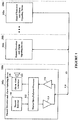
- FIG. 1 depicted is a schematic block diagram of a hazard detection and alarm signaling system having a plurality of hazard detection and alarm signaling devices coupled together with an input-output (IO) bus, according to a specific example embodiment of this disclosure.
- a plurality of hazard detection and alarm signaling devices 102 are located in spatially diverse locations (e.g., rooms) 104, and coupled together with an IO bus 118.
- Each of the plurality of hazard detection and alarm signaling devices 102 may comprise a hazard detector 106, an alarm alert generator 108, an audible sound reproducer 110, master/slave/follower processor 112, an IO bus driver 114 and an IO bus receiver 116.
- the hazard detector 106 may detect, for example but is not limited to, smoke, carbon monoxide, radon, gas, chlorine, moisture, etc.
- the audible sound reproducer 110 may be, for example but is not limited to, a speaker, a piezo-electric transducer, a buzzer, a bell, etc.
- the master/slave/follower processor 112 may comprise, but is not limited to, a microcontroller and program memory, a microcomputer and program memory, an application specific integrated circuit (ASIC), a programmable logic array (PLA), etc.
- the interconnection of the plurality of hazard detection and alarm signaling devices 102 with the IO bus 118 may be accomplished by conventional means well known to those skilled in the art of electronics and use industry standard drivers, receivers and bus loading techniques. However since the interconnect protocol described herein is new, novel and non-obvious, other newer and more sophisticated means of interconnection may also be applied with equal or better effectiveness. It is contemplated and within the scope of this disclosure that the IO bus 118 may also be implemented as a wireless data network, e.g ., Bluetooth, Zigbee, WiFi, WLAN, AC line carrier current, etc.
- a wireless data network e.g ., Bluetooth, Zigbee, WiFi, WLAN, AC line carrier current, etc.
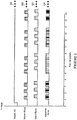
- a master device 102 goes into an alarm condition and drives the IO bus 118 high with a master IO signal 218.
- the master device 102 emits audible alert tone pulses 220 at defined time intervals, for example but not limited to, groups of three alert tone pulses at four (4) second cycles per the National Fire Protection Association (NFPA) 72: National Fire Alarm and Signaling Code.
- NFPA National Fire Protection Association
- At least one of the other devices 102 not necessarily in alarm, repeats the three alert tone pulses 222. However there is no way to synchronize the tone pulses 220 from the master device 102 in alarm and the tone pulses 222 from the at least one of the other devices 102.
- Resulting apparent tone pulses 224 are shown having examples of various off synchronization phasing resulting in a jumble of confusing tones that do not clearly annunciate an alarm condition.
- a master device 102 goes into an alarm condition and drives the IO bus 118 high with a master IO signal 318 starting at time T 0 , and periodically goes low to provide a synchronization signal to all other devices 102 connected to the IO bus 118, as more fully described hereinafter.
- the master device 102 may emit audible alert tone pulses 320 at defined time intervals, for example but not limited to, groups of three alert tone pulses at four (4) second cycles per the National Fire Protection Association (NFPA) 72: National Fire Alarm and Signaling Code.
- NFPA National Fire Protection Association
- the start of a group of three tone pulses 320 may occur after a time, T 1 , from a positive going edge of the master IO signal 318, and thereafter be synchronized thereto.
- At least one of the other devices 102 may repeat with the three alert tone pulses 322 in synchronization with the positive going edges of the master IO signal 318.
- the resulting apparent tone pulses 324 are audibly reinforced from the synchronized tone pulses 320 and 322, thereby clearly annunciating an alarm condition.
- the remote devices 102 may synchronize to the rising edge of the master IO signal 318 with a delay of time T 1 before starting the remote horn alert tone pulses 322.
- the originating device 102 anticipates a delay for the master IO signal 318 such that timing for the originating (master) and remote alarm alert tone pulses 320 and 322 are substantially the same.
- Figure 3A illustrates schematic timing diagrams of temporal audible alarm signals that are synchronized together and have an automatic audible alarm origination locate feature, according to a specific example embodiment of this disclosure.
- a master device (first device to go into local alarm) drives the IO bus 118 with the master IO signal 318a.
- all non-master devices 102 Upon a change in the logic level of the master IO signal 318a on the IO bus 118, all non-master devices 102 will synchronize their groups of three tone pulses after a time period T 1 , as more fully described hereinafter. Therefore, only those devices 102 in local alarm will have continuous pulse patterns, and slave devices not in local alarm will skip (suppress) every fourth group of tone pulses 322a. This facilitates finding alarm devices in local alarm by just observing which alarm devices sound tone pulse groups continuously without interruption.
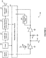
- FIG. 4 depicted is a schematic block diagram of a hazard detection and alarm signaling device shown in Figure 1 , according to a specific example embodiment of this disclosure.
- the hazard detection and alarm signaling device 102 is as described in Figure 1 hereinabove, wherein the IO bus driver 114 may have a constant current output determined by the constant current source 420, and is tri-stated such that its output may be placed in a high impedance state.
- a bus load resistor 422 acts as a soft pull-down when the IO bus driver 114 is in the high impedance output state.
- An output from the IO bus receiver 116 is coupled to a first input of the master/slave/follower processor 112 and a time delayed output from a time delay filter 424 is coupled to a second input of the master/slave/follower processor 112.
- the time delay filter 424 may be configured for, but is not limited to, a delay of 320 milliseconds plus or minus three (3) percent wherein pulses of 300 milliseconds or less are ignored, e.g., no output from the time delay filter 424. These two signals (outputs to B and C) may be used in combination to insure that false triggering of the plurality of hazard detection and alarm signaling devices 102 do not occur.
- the hazard detector 106 is coupled to an input of the master/slave/follower processor 112 and provides an output signal when a hazard is detected.
- the alarm alert generator 108 shown in Figure 1 may comprise a clock 426, audio tone generator 428, an audio tone pulse synchronization circuit 430 and an audio power amplifier 432 for driving the audible sound reproducer 110. Other combinations of circuit functions can be used for the alarm alert generator 108 as would be known to one having ordinary skill in electronic design and the benefit of this disclosure.
- the audio tone pulse synchronization circuit 430 may be controlled by the master/slave/follower processor 112, or may be part of it, to provide audible alert tone pulses 320 if a master device 102 detects an alarm condition, or to provide synchronized tone pulses 322, if a slave or follower device 102, based upon the rising positive edges of the master IO signal 318 (see Figure 3 ).
- the time delay filter 424 may be separate from or part of the master/slave/follower processor 112, and may be accomplished in hardware and/or software as would be known to one having ordinary skill in digital microcontroller design and having the benefit of this disclosure.
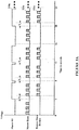
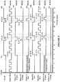
- FIG. 5 depicted are schematic timing diagrams of temporal audible alarm and control signals of the hazard detection and alarm signaling devices shown in Figures 1 and 4 , according to a specific example embodiment of this disclosure.
- a hazard detection and alarm signaling device 102 When a hazard detection and alarm signaling device 102 is first to go into a local alarm, e.g., local hazard detected by the hazard detector 106 of that device 102, it becomes the "master" device 102. Wherein audible alert tone pulses 320 begin issuing therefrom.
- a local alarm e.g., local hazard detected by the hazard detector 106 of that device 102
- audible alert tone pulses 320 begin issuing therefrom.
- the master device 102 After the first set of three pulses 320, the master device 102 asserts a signal 518 at a logic high, e.g., a voltage or current, positive or negative with reference to a zero voltage or current when no other master IO signal 518 has previously been asserted for a certain length of time, e.g ., seven (7) seconds.
- a first assertion of the master IO signal 518 occurs at time T 0 which is after the first set of audible alert tone pulses 320, and continues asserted until after the end of the next set of three audible alert tone pulses 320.
- the master IO signal 518 is at a logic low no slave devices 102 will generate a synchronized group of tone pulses therefrom. Therefore, only master and follower devices 102 in local alarm will have continuous tone pulse groups, as more fully explained hereinabove and shown in Figure 3A .
- the start of the next set of three audible alert tone pulses 320 occurs after time T 1 has elapsed.
- the master IO signal 518 is asserted at a logic low on the IO bus 118.
- the logic low thereon discharges any residual voltage or current on the IO bus 118 from the logic high previously thereon.
- a master IO high-drive is shown as signal 530 corresponds to logic highs asserted on the IO bus 118 by the master IO signal 518
- a master IO low dump is shown as signal 532 and corresponds to logic lows asserted on the IO bus 118 by the master IO signal 518 for residual voltage discharge therefrom.
- a master IO high impedance signal 534 is at a logic high which indicates that the IO bus 118 is in a "high impedance" state so that a Follower device 102 in alarm may become a Master if the present Master device 102 is no longer in an alarm condition.
- the master IO high impedance signal 540 represents when contention windows for the IO bus driver 114 of the present Master device 102 briefly goes into an off or high impedance output state for time T 4 .
- another Follower device 102 in alarm can attempt to "grab" the IO bus 118 and become a Master device 102, but only when there is no logic high asserted on the IO bus 118 for a certain time period, e.g., about seven (7) seconds.
- the Follower device 102 also has at least one contention window represented by the follower IO high drive signal 540.
- the follower IO high drive signal 540 also represents when a Follower device 102 is in alarm and tries to become a Master during a portion of the time T 6 .
- the time delay filter 424 is used to prevent unintended alarm actuation of Slave and/or Follower devices 102 from a logic high asserted on the IO bus 118 for less than a desired time period, e.g., 320 milliseconds +/- three (3) percent, and that the time delay filter 424 will not operate, e.g ., assert a received logic high signal at input B of the processor 112 for an input from the IO bus 108 of less than a certain verification time period, e.g., about 300 milliseconds or less.
- a desired time period e.g., 320 milliseconds +/- three (3) percent
- the Slave/Follower audible alert tone pulses 322 begin issuing therefrom after another time period T 3 has elapsed.
- T 1 is defined as being equal to the sum of T 2 and T 3 , even though the time delay filter introduces a delay time, e.g., time period T 2 , the audible alert tone pulses 320 and 322 will be synchronized and acoustically coherent.
- a Master is in local alarm and drive the IO bus 118 to a logic high
- a follower is in local alarm but does not drive the IO bus 118 to a logic high, rather it synchronizes to the positive edges of the signal 518 on the IO bus 118
- a Slave in remote alarm synchronizes to the positive edges of the signal 518 on the IO bus 118. All audible alert tone pulses 320 and 322 are thereby synchronized and acoustically coherent.
- a device is in remote alarm before going into local alarm, this device will now become a Follower instead of a Slave.
- the Master device 102 goes from the Master state to a Follower state.
- the follower state if the device is in the follower state and the IO bus 118 is low for longer than a certain time period, e.g., seven (7) seconds then the Follower becomes the Master of the IO bus 118.
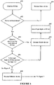
- step 650 the IO bus 118 is monitored by each of the devices 102.
- step 652 determines whether a device 102 is in a local alarm. If not in a local alarm, then in step 664 the device 102 becomes/remains a Slave device. If the device is in a local alarm, then step 654 determines if a positive going logic level, e.g., logic low to logic high, is detected on the IO bus 118 (output of bus receiver 116).
- a positive going logic level e.g., logic low to logic high
- step 656 determines whether the logic high remains asserted on the IO bus 118 for a time T 2 (output of time delay filter 424). If the logic high does not remain asserted on the IO bus 118 for the time T 2 , then in step 660 the device 102 becomes an IO bus Master, and in step 662 the new IO bus Master asserts a logic high onto the IO bus 118. However, if a logic high on the IO bus 118 does remain for time T 2 , then in step 658 the device 102 becomes a Follower device.
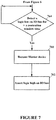
- step 764 determines whether during a contention time window there is not a logic high present on the IO bus 108 for a contention window time.
- step 760 a previous Follower device 102 will become the Master device 102, and in step 762 the new Master device 102 will then assert a logic high on the IO bus 108 at the appropriate times for synchronizing the audible alert tone pulses 322 from the other Follower and Slave devices 102, as more fully described hereinabove.
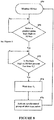
- FIG. 8 depicted is a schematic process flow diagram for synchronizing alert tones from the Follower and Slave devices to the alert tones from the Master device, according to a specific example embodiment of this disclosure.
- the status of each of the devices 102 is determined, i.e., which one of the devices 102 is the Master, and the other devices 102 are Followers and Slaves depending on whether they are also in local alarm or not, respectively.
- the Master yields to the other device 102 driving the IO bus 118 and assumes Follower status.
- Steps 650, 651 and 652 from Figure 6 are shown again for clarity.
- the logic in each device will wait a time T 3 before starting a three alert tone sequence in step 876.
Landscapes
- Physics & Mathematics (AREA)
- Electromagnetism (AREA)
- General Physics & Mathematics (AREA)
- Engineering & Computer Science (AREA)
- Acoustics & Sound (AREA)
- Signal Processing (AREA)
- Alarm Systems (AREA)
Claims (15)
- Verfahren zur automatischen Tonalarmortung, das die nachfolgenden Schritte aufweist:Bereitstellen eines Eingangs-Ausgangs-Bus (118), der eine räumlich verteilte Vielzahl von Gefahrendetektions- und Alarmanordnungen (102a, 102b ... 102n) miteinander koppelt;Überwachen eines Gefahrendetektors (106) innerhalb jeder der Vielzahl von Gefahrendetektions- und Alarmanordnungen (102a, 102b ... 102n) und wenn ein lokales Alarmsignal von dem Gefahrendetektor (106) eines der Vielzahl von Gefahrendetektions- und Alarmanordnungen (102a, 102b ... 102n) detektiert wird, die entsprechende Anordnung zu einer Master-Anordnung machen und Aktivieren eines zweiten Logikpegels auf dem Eingangs-Ausgangs-Bus (118);Feststellen, durch die verbleibenden Gefahrendetektions- und Alarmanordnungen (102a, 102b ... 102n), wenn der Eingangs-Ausgangs-Bus (118) von einem ersten Logikpegel auf einen zweite Logikpegel geht;
Feststellen, durch jede der verbleibenden Gefahrendetektions- und Alarmanordnungen (102a, 102b ... 102n), ob der zweite Logikpegel auf dem Eingangs-Ausgangs-Bus (118) aktiviert wurde, und wenn dies der Fall ist, dann Bestimmen, durch jede der verbleibenden Gefahrendetektions- und Alarmanordnungen (102a, 102b ... 102n), ob sie sich in einem Lokalen Alarmzustand befinden oder ob sie sich nicht in dem lokalen Alarmzustand befinden, wobei jede, die sich in dem lokalen Alarmzustand befindet als eine Follower-Anordnung bestimmt wird und jede, die sich nicht in dem lokalen Alarmzustand befindet, als eine Slave-Anordnung bestimmt wird,Aktivieren des ersten Logikpegels auf dem Eingangs-Ausgangs-Bus mit der Master-Anordnung für kurze Zeitdauern zwischen Aktivieren des zweiten Logikpegels auf diesen, um Gruppen von Alarmtonimpulsen von den Master-, Follower- und Slave-Anordnungen zu synchronisieren, wobei Alarmtonimpulsgruppen von der Slave-Anordnung nur dann auftreten werden, wenn der Eingangs-Ausgangs-Bus den zweiten Logikpegel aufweist und wobei die Master-Anordnung den ersten Logikpegel auf dem Eingangs-Ausgangs-Bus für zumindest eine Gruppe von Alarmtonimpulsen periodisch aktiviert. - Verfahren gemäß Anspruch 1, das weiterhin die Schritte aufweist:Warten einer vorgegebenen Zeitdauer (T1) nach dem feststellen, dass der zweite Logikpegel für die erste Zeitdauer auf dem Eingangs-Ausgangs-Bus verblieben ist; undAktivieren einer synchronisierten Gruppe von Alarmtonimpulse von den Follower- und Slave-Anordnungen (102a, 102b ... 102n).
- Verfahren gemäß Anspruch 1 oder 2, das weiterhin die Schritte aufweist:
Ausgeben einer ersten Gruppe von Alarmtonimpulsen durch die Master-Anordnung vor Aktivieren des zweiten Logikpegels auf dem Eingangs-Ausgangs-Bus (118). - Verfahren gemäß einem der vorherigen Ansprüche, das weiterhin die Schritte aufweist:
Feststellen, ob der Eingangs-Ausgangs-Bus für eine bestimmte Zeitdauer während eines Konfliktzeitfenster bei dem ersten Logikpegel verbleibt, wobeiwenn dies der Fall ist, dann eine der Follower-Anordnungen zu einer neuen Master-Anordnung machen und die neue Master-Anordnung den zweiten Logikpegel auf dem Eingangs-Ausgangs-Bus (118) aktivieren lassen; undwenn dies nicht der Fall ist, dann Beibehalten des vorherigen Status für jede der Master-, Follower- und Slave-Anordnungen (102a, 102b ... 102n). - Verfahren gemäß einem der vorherigen Ansprüche, wobei während der kurzen Zeitdauern der Master den ersten Logikpegel für eine erste Zeitdauer (T5) aktiviert, dann danach für eine zweite Zeitdauer (T4) keinen Logikpegel auf dem Eingangs-Ausgangs-Bus (118) aktiviert.
- Verfahren gemäß einem der vorherigen Ansprüche, wobei die Master-Anordnung nach drei aufeinanderfolgenden Gruppen von Alarmtonimpulsen für eine Gruppe von Alarmtonimpulse den ersten Logikpegel auf dem Eingangs-Ausgangs-Bus aktiviert.
- Verfahren gemäß einem der vorherigen Ansprüche, wobei die ersten und zweiten Logikpegel unterschiedliche Spannungswerte auf dem Eingangs-Ausgangs-Bus oder unterschiedliche Stromwerte in den Eingangs-Ausgangs-Bus aufweisen.
- Verfahren gemäß einem der vorherigen Ansprüche, wobei jede Gruppe der Alarmtonimpulse drei Tonimpulse innerhalb etwa vier Sekunden aufweist.
- Verfahren gemäß einem der vorherigen Ansprüche, wobei die Vielzahl von Gefahrendetektions- und Alarmanordnungen dazu befähigt sind, Gefahren zu detektieren die aus der Gruppe bestehend aus Feuer, Rauch, Kohlenmonoxid, Radon, Erdgas, Chlorgas, Wasser und Feuchtigkeit ausgewählt sind.
- Gefahrendetektions- und Alarmsystem, wobei das System aufweist:eine Vielzahl von Gefahrendetektions- und Alarmanordnungen (102a, 102b ... 102n), die mit einem Eingangs-Ausgangs-Bus (118) miteinander gekoppelt sind, wobei die Vielzahl von Gefahrendetektions- und Alarmanordnungen (102a, 102b ... 102n) räumlich verteilt ist;wobeieine der Vielzahl von Gefahrendetektions- und Alarmanordnungen (102a, 102b ... 102n) ein Master wird, wenn sie sich in einem lokalen Alarmzustand befindet, andere der Vielzahl von Gefahrendetektions- und Alarmanordnungen (102a, 102b ... 102n) Follower werden, wenn sie sich in einem lokalen Alarmzustand befinden, der nach dem Auftreten des lokalen Alarms des Masters aufgetreten ist, und noch andere der Vielzahl von Gefahrendetektions- und Alarmanordnungen (102a, 102b ... 102n) zu Slaves werden, wenn sie sich nicht in einem lokalen Alarmzustand befinden; und wobeider Master konfiguriert ist, einen zweiten Logikpegel auf dem Eingangs-Ausgangs-Bus (118) zu aktivieren, der zuvor einen ersten Logikpegel aufwies, dann periodisch für kurze Zeitdauern den ersten Logikpegel auf dem Eingangs-Ausgangs-Bus (118) aktiviert und danach den zweiten Logikpegel auf dem Eingangs-Ausgangs-Bus reaktiviert, wobei alle Follower und Slaves ihre Alarmtonimpulsgruppen synchronisieren, um Tongruppen des Masters zu alarmieren, wenn der Eingangs-Ausgangs-Bus (118) von dem ersten Logikpegel auf den zweiten Logikpegel geht und auf dem zweiten Logikpegel verbleibt;wobei Alarmtonimpulsgruppen der Slave-Anordnungen nur dann auftreten, wenn sich der Eingangs-Ausgangs-Bus (118) den zweiten Logikpegel aufweist und wobei die Master-Anordnung weiterhin konfiguriert ist, den ersten Logikpegel auf dem Eingangs-Ausgangs-Bus periodisch für zumindest eine Gruppe von Alarmtonimpulsen zu aktivieren.
- System gemäß Anspruch 10, wobei, wenn einer der Follower in lokalem Alarmzustand feststellt, dass sich der Eingangs-Ausgangs-Bus für eine bestimmte Zeit auf dem ersten Logikpegel befindet, dieser Follower der Master wird und danach den zweiten Logikpegel auf dem Eingangs-Ausgangs-Bus aktiviert.
- System gemäß Anspruch 10 oder 11, wobei während der kurzen Zeitdauer der Master konfiguriert ist, den ersten Logikpegel für eine erste Zeitdauer (T5) zu aktivieren, dann danach für eine zweite Zeitdauer (T4) keinen Logikpegel auf dem Eingangs-Ausgangs-Bus (118) aktiviert.
- System gemäß einem der vorherigen Ansprüche 10 bis 12, wobei die Vielzahl von Gefahrendetektions- und Alarmanordnungen (102a, 102b ... 102n) zumindest einen Sensor aufweisen der befähigt ist, zumindest einen Gefahrenzustand festzustellen, der aus einem oder mehreren der Gruppe bestehend aus Feuer, Rauch, Kohlenmonoxid, Radon, Erdgas, Chlorgas, Wasser und Feuchtigkeit ausgewählt ist.
- System gemäß einem der vorherigen Ansprüche 10 bis 13, wobei jede der Vielzahl von Gefahrendetektions- und Alarmanordnungen aufweist:einen Gefahrendetektor (106);einen Alarmwarngenerator (428, 430);ein Hörschallwiedergabegerät (110), das mit einem Ausgang des Alarmwarngenerators (428) gekoppelt ist;einen Digitalprozessor (112), der einen ersten Eingang aufweist, der zum Empfangen eines Gefahrendetektionssignals mit dem Gefahrendetektor (106) gekoppelt ist und einen ersten Ausgang aufweist, der mit dem Alarmwarngenerator (430) gekoppelt ist um diesen zu steuern;einen Bustreiber (114), der einen mit einem zweiten Ausgang des Digitalprozessors (112) gekoppelten Eingang und einen mit dem Eingangs-Ausgangs-Bus (118) gekoppelten Ausgang aufweist;einen Busempfänger (116), der einen mit dem Eingangs-Ausgangs-Bus (118) gekoppelten Eingang und einen mit einem zweiten Eingang des Digitalprozessors (112) gekoppelten Ausgang aufweist; undein Zeitverzögerungsfilter (424), das einen mit dem Ausgang des Busempfängers (116) gekoppelten Eingang und einen mit einem dritten Eingang des Digitalprozessors (112) gekoppelten Ausgang aufweist.
- System gemäß Anspruch 14, wobei der Digitalprozessor (112), vorzugsweise ein Mikrocontroller, einen Master-, Follower- oder Slave-Zustand der Gefahrendetektions- und Alarmanordnung festlegt.
Applications Claiming Priority (3)
| Application Number | Priority Date | Filing Date | Title |
|---|---|---|---|
| US201161558509P | 2011-11-11 | 2011-11-11 | |
| US13/665,459 US8723672B2 (en) | 2011-11-11 | 2012-10-31 | Automatic audible alarm origination locate |
| PCT/US2012/064339 WO2013071032A1 (en) | 2011-11-11 | 2012-11-09 | Automatic audible alarm origination locate |
Publications (2)
| Publication Number | Publication Date |
|---|---|
| EP2777030A1 EP2777030A1 (de) | 2014-09-17 |
| EP2777030B1 true EP2777030B1 (de) | 2018-09-26 |
Family
ID=48280039
Family Applications (1)
| Application Number | Title | Priority Date | Filing Date |
|---|---|---|---|
| EP12798489.6A Active EP2777030B1 (de) | 2011-11-11 | 2012-11-09 | Automatische tonalarmortung |
Country Status (6)
| Country | Link |
|---|---|
| US (1) | US8723672B2 (de) |
| EP (1) | EP2777030B1 (de) |
| KR (1) | KR101961869B1 (de) |
| CN (1) | CN104025164B (de) |
| TW (1) | TWI584235B (de) |
| WO (1) | WO2013071032A1 (de) |
Families Citing this family (6)
| Publication number | Priority date | Publication date | Assignee | Title |
|---|---|---|---|---|
| SE536754C2 (sv) * | 2012-11-22 | 2014-07-15 | Interactive Inst Ii Ab | Metod och anordning för att generera en auditiv underrättelsesignal |
| US20160171858A1 (en) * | 2014-12-10 | 2016-06-16 | Jonas Patrik TRUMPHY | Alarm systems for detecting and communicating anomalous events |
| EP3748599B1 (de) * | 2019-06-03 | 2021-07-28 | Siemens Schweiz AG | Verfahren zum betrieb und tests eines gefahrenmeldesystems mit einem bussystem, melder zum anschluss an ein bussystem und gefahrenmeldesystem mit einem bussystem. |
| CN110671789B (zh) * | 2019-09-17 | 2021-02-26 | 珠海格力电器股份有限公司 | 一种故障机定位方法、装置及空调机组 |
| FR3112230A1 (fr) * | 2020-07-06 | 2022-01-07 | Cordia | Procédé et système pour gérer la diffusion de messages vocaux au sein d’espaces |
| US11875664B2 (en) | 2021-06-04 | 2024-01-16 | Smart Cellular Labs, Llc | Integrated smoke alarm communications system |
Family Cites Families (13)
| Publication number | Priority date | Publication date | Assignee | Title |
|---|---|---|---|---|
| US5608375A (en) * | 1995-03-20 | 1997-03-04 | Wheelock Inc. | Synchronized visual/audible alarm system |
| US6906616B1 (en) | 1995-03-20 | 2005-06-14 | Wheelock, Inc. | Apparatus and method for synchronizing visual/audible alarm units in an alarm system |
| JP3658696B2 (ja) * | 1996-03-29 | 2005-06-08 | 能美防災株式会社 | 防災設備 |
| US6028513A (en) * | 1998-02-27 | 2000-02-22 | Pittway Corporation | Wireless activation of multiple alarm devices upon triggering of a single device |
| US6897772B1 (en) * | 2000-11-14 | 2005-05-24 | Honeywell International, Inc. | Multi-function control system |
| US6614347B2 (en) | 2001-01-30 | 2003-09-02 | Ranco Inc. | Apparatus and method for providing alarm synchronization among multiple alarm devices |
| US7075444B2 (en) | 2002-11-15 | 2006-07-11 | Maple Chase Company | Temporary alarm locate with intermittent warning |
| FR2880456B1 (fr) * | 2005-01-03 | 2007-02-23 | Airbus France Sas | Procede et dispositif d'alerte sonore lors de la desactivation d'un pilote automatique d'un aeronef |
| US7880604B2 (en) | 2005-09-20 | 2011-02-01 | Selflink, Llc | Self-configuring emergency event alarm system with autonomous output devices |
| US7893825B2 (en) | 2007-11-20 | 2011-02-22 | Universal Security Instruments, Inc. | Alarm origination latching system and method |
| AU2008332565B2 (en) | 2007-12-06 | 2012-07-19 | Hochiki Corporation | Alarm device and alarm system |
| GB2457307A (en) | 2008-02-11 | 2009-08-12 | Apollo Fire Detectors Ltd | Fire alarm signalling with voice modulated HF signal multiplexed on to plateaus of existing lower frequency pulses carried on power cabling |
| JP5213672B2 (ja) * | 2008-12-05 | 2013-06-19 | 能美防災株式会社 | 警報システム及び警報器 |
-
2012
- 2012-10-31 US US13/665,459 patent/US8723672B2/en active Active
- 2012-11-09 TW TW101141916A patent/TWI584235B/zh active
- 2012-11-09 KR KR1020147015178A patent/KR101961869B1/ko active Active
- 2012-11-09 WO PCT/US2012/064339 patent/WO2013071032A1/en not_active Ceased
- 2012-11-09 EP EP12798489.6A patent/EP2777030B1/de active Active
- 2012-11-09 CN CN201280065706.5A patent/CN104025164B/zh active Active
Non-Patent Citations (1)
| Title |
|---|
| None * |
Also Published As
| Publication number | Publication date |
|---|---|
| KR101961869B1 (ko) | 2019-03-26 |
| TWI584235B (zh) | 2017-05-21 |
| CN104025164B (zh) | 2017-06-16 |
| EP2777030A1 (de) | 2014-09-17 |
| WO2013071032A1 (en) | 2013-05-16 |
| KR20140089422A (ko) | 2014-07-14 |
| US20130120143A1 (en) | 2013-05-16 |
| CN104025164A (zh) | 2014-09-03 |
| US8723672B2 (en) | 2014-05-13 |
| TW201333895A (zh) | 2013-08-16 |
Similar Documents
| Publication | Publication Date | Title |
|---|---|---|
| EP2777029B1 (de) | Temporäre warnsignalmustersynchronisation | |
| EP2777030B1 (de) | Automatische tonalarmortung | |
| CN101352051B (zh) | 在安全系统中产生语音警报信号的方法和装置 | |
| JP2008009480A (ja) | 無線により連動警報するワイヤレス型火災警報器、及びワイヤレス型火災警報システム | |
| CN106658698A (zh) | 使用无线通信的无线控制的通知设备的同步 | |
| JP4713854B2 (ja) | 警報器 | |
| JP5122873B2 (ja) | 住宅用火災警報器 | |
| JP4710877B2 (ja) | 火災警報システム | |
| JP2003044955A (ja) | 住宅用火災警報器及びそれを用いた住宅用火災警報システム | |
| JP2004145464A (ja) | 火災受信機 | |
| JP5990936B2 (ja) | 自動火災報知システム | |
| JP5097834B2 (ja) | 防災受信機 | |
| JP5121855B2 (ja) | 警報器 | |
| JP4873975B2 (ja) | 警報器 | |
| JP5323411B2 (ja) | 火災報知設備の音響停止装置 | |
| JP2010108516A (ja) | 警報器 | |
| JP5123957B2 (ja) | 警報器 | |
| JP3864922B2 (ja) | 自火報受信機 | |
| JP2007198993A (ja) | 生活見守り報時時計システム | |
| JP2001338359A (ja) | 地区音響装置の鳴動方法及び火災受信機 | |
| JPH0388100A (ja) | 火災受信機 |
Legal Events
| Date | Code | Title | Description |
|---|---|---|---|
| PUAI | Public reference made under article 153(3) epc to a published international application that has entered the european phase |
Free format text: ORIGINAL CODE: 0009012 |
|
| 17P | Request for examination filed |
Effective date: 20140610 |
|
| AK | Designated contracting states |
Kind code of ref document: A1 Designated state(s): AL AT BE BG CH CY CZ DE DK EE ES FI FR GB GR HR HU IE IS IT LI LT LU LV MC MK MT NL NO PL PT RO RS SE SI SK SM TR |
|
| DAX | Request for extension of the european patent (deleted) | ||
| GRAP | Despatch of communication of intention to grant a patent |
Free format text: ORIGINAL CODE: EPIDOSNIGR1 |
|
| STAA | Information on the status of an ep patent application or granted ep patent |
Free format text: STATUS: GRANT OF PATENT IS INTENDED |
|
| RIC1 | Information provided on ipc code assigned before grant |
Ipc: G08B 25/04 20060101ALN20180413BHEP Ipc: H04R 3/12 20060101ALN20180413BHEP Ipc: G08B 3/10 20060101AFI20180413BHEP |
|
| INTG | Intention to grant announced |
Effective date: 20180516 |
|
| GRAS | Grant fee paid |
Free format text: ORIGINAL CODE: EPIDOSNIGR3 |
|
| GRAA | (expected) grant |
Free format text: ORIGINAL CODE: 0009210 |
|
| STAA | Information on the status of an ep patent application or granted ep patent |
Free format text: STATUS: THE PATENT HAS BEEN GRANTED |
|
| AK | Designated contracting states |
Kind code of ref document: B1 Designated state(s): AL AT BE BG CH CY CZ DE DK EE ES FI FR GB GR HR HU IE IS IT LI LT LU LV MC MK MT NL NO PL PT RO RS SE SI SK SM TR |
|
| REG | Reference to a national code |
Ref country code: GB Ref legal event code: FG4D |
|
| REG | Reference to a national code |
Ref country code: CH Ref legal event code: EP |
|
| REG | Reference to a national code |
Ref country code: AT Ref legal event code: REF Ref document number: 1046933 Country of ref document: AT Kind code of ref document: T Effective date: 20181015 |
|
| REG | Reference to a national code |
Ref country code: IE Ref legal event code: FG4D |
|
| REG | Reference to a national code |
Ref country code: DE Ref legal event code: R096 Ref document number: 602012051559 Country of ref document: DE |
|
| REG | Reference to a national code |
Ref country code: FR Ref legal event code: PLFP Year of fee payment: 7 |
|
| REG | Reference to a national code |
Ref country code: NL Ref legal event code: MP Effective date: 20180926 |
|
| PG25 | Lapsed in a contracting state [announced via postgrant information from national office to epo] |
Ref country code: FI Free format text: LAPSE BECAUSE OF FAILURE TO SUBMIT A TRANSLATION OF THE DESCRIPTION OR TO PAY THE FEE WITHIN THE PRESCRIBED TIME-LIMIT Effective date: 20180926 Ref country code: LT Free format text: LAPSE BECAUSE OF FAILURE TO SUBMIT A TRANSLATION OF THE DESCRIPTION OR TO PAY THE FEE WITHIN THE PRESCRIBED TIME-LIMIT Effective date: 20180926 Ref country code: BG Free format text: LAPSE BECAUSE OF FAILURE TO SUBMIT A TRANSLATION OF THE DESCRIPTION OR TO PAY THE FEE WITHIN THE PRESCRIBED TIME-LIMIT Effective date: 20181226 Ref country code: NO Free format text: LAPSE BECAUSE OF FAILURE TO SUBMIT A TRANSLATION OF THE DESCRIPTION OR TO PAY THE FEE WITHIN THE PRESCRIBED TIME-LIMIT Effective date: 20181226 Ref country code: GR Free format text: LAPSE BECAUSE OF FAILURE TO SUBMIT A TRANSLATION OF THE DESCRIPTION OR TO PAY THE FEE WITHIN THE PRESCRIBED TIME-LIMIT Effective date: 20181227 Ref country code: RS Free format text: LAPSE BECAUSE OF FAILURE TO SUBMIT A TRANSLATION OF THE DESCRIPTION OR TO PAY THE FEE WITHIN THE PRESCRIBED TIME-LIMIT Effective date: 20180926 Ref country code: SE Free format text: LAPSE BECAUSE OF FAILURE TO SUBMIT A TRANSLATION OF THE DESCRIPTION OR TO PAY THE FEE WITHIN THE PRESCRIBED TIME-LIMIT Effective date: 20180926 |
|
| REG | Reference to a national code |
Ref country code: LT Ref legal event code: MG4D |
|
| PG25 | Lapsed in a contracting state [announced via postgrant information from national office to epo] |
Ref country code: AL Free format text: LAPSE BECAUSE OF FAILURE TO SUBMIT A TRANSLATION OF THE DESCRIPTION OR TO PAY THE FEE WITHIN THE PRESCRIBED TIME-LIMIT Effective date: 20180926 Ref country code: LV Free format text: LAPSE BECAUSE OF FAILURE TO SUBMIT A TRANSLATION OF THE DESCRIPTION OR TO PAY THE FEE WITHIN THE PRESCRIBED TIME-LIMIT Effective date: 20180926 Ref country code: HR Free format text: LAPSE BECAUSE OF FAILURE TO SUBMIT A TRANSLATION OF THE DESCRIPTION OR TO PAY THE FEE WITHIN THE PRESCRIBED TIME-LIMIT Effective date: 20180926 |
|
| REG | Reference to a national code |
Ref country code: AT Ref legal event code: MK05 Ref document number: 1046933 Country of ref document: AT Kind code of ref document: T Effective date: 20180926 |
|
| PG25 | Lapsed in a contracting state [announced via postgrant information from national office to epo] |
Ref country code: IT Free format text: LAPSE BECAUSE OF FAILURE TO SUBMIT A TRANSLATION OF THE DESCRIPTION OR TO PAY THE FEE WITHIN THE PRESCRIBED TIME-LIMIT Effective date: 20180926 Ref country code: EE Free format text: LAPSE BECAUSE OF FAILURE TO SUBMIT A TRANSLATION OF THE DESCRIPTION OR TO PAY THE FEE WITHIN THE PRESCRIBED TIME-LIMIT Effective date: 20180926 Ref country code: PL Free format text: LAPSE BECAUSE OF FAILURE TO SUBMIT A TRANSLATION OF THE DESCRIPTION OR TO PAY THE FEE WITHIN THE PRESCRIBED TIME-LIMIT Effective date: 20180926 Ref country code: AT Free format text: LAPSE BECAUSE OF FAILURE TO SUBMIT A TRANSLATION OF THE DESCRIPTION OR TO PAY THE FEE WITHIN THE PRESCRIBED TIME-LIMIT Effective date: 20180926 Ref country code: IS Free format text: LAPSE BECAUSE OF FAILURE TO SUBMIT A TRANSLATION OF THE DESCRIPTION OR TO PAY THE FEE WITHIN THE PRESCRIBED TIME-LIMIT Effective date: 20190126 Ref country code: ES Free format text: LAPSE BECAUSE OF FAILURE TO SUBMIT A TRANSLATION OF THE DESCRIPTION OR TO PAY THE FEE WITHIN THE PRESCRIBED TIME-LIMIT Effective date: 20180926 Ref country code: NL Free format text: LAPSE BECAUSE OF FAILURE TO SUBMIT A TRANSLATION OF THE DESCRIPTION OR TO PAY THE FEE WITHIN THE PRESCRIBED TIME-LIMIT Effective date: 20180926 Ref country code: RO Free format text: LAPSE BECAUSE OF FAILURE TO SUBMIT A TRANSLATION OF THE DESCRIPTION OR TO PAY THE FEE WITHIN THE PRESCRIBED TIME-LIMIT Effective date: 20180926 Ref country code: CZ Free format text: LAPSE BECAUSE OF FAILURE TO SUBMIT A TRANSLATION OF THE DESCRIPTION OR TO PAY THE FEE WITHIN THE PRESCRIBED TIME-LIMIT Effective date: 20180926 |
|
| PG25 | Lapsed in a contracting state [announced via postgrant information from national office to epo] |
Ref country code: SK Free format text: LAPSE BECAUSE OF FAILURE TO SUBMIT A TRANSLATION OF THE DESCRIPTION OR TO PAY THE FEE WITHIN THE PRESCRIBED TIME-LIMIT Effective date: 20180926 Ref country code: PT Free format text: LAPSE BECAUSE OF FAILURE TO SUBMIT A TRANSLATION OF THE DESCRIPTION OR TO PAY THE FEE WITHIN THE PRESCRIBED TIME-LIMIT Effective date: 20190126 Ref country code: SM Free format text: LAPSE BECAUSE OF FAILURE TO SUBMIT A TRANSLATION OF THE DESCRIPTION OR TO PAY THE FEE WITHIN THE PRESCRIBED TIME-LIMIT Effective date: 20180926 |
|
| REG | Reference to a national code |
Ref country code: DE Ref legal event code: R097 Ref document number: 602012051559 Country of ref document: DE |
|
| REG | Reference to a national code |
Ref country code: CH Ref legal event code: PL |
|
| PG25 | Lapsed in a contracting state [announced via postgrant information from national office to epo] |
Ref country code: LU Free format text: LAPSE BECAUSE OF NON-PAYMENT OF DUE FEES Effective date: 20181109 Ref country code: DK Free format text: LAPSE BECAUSE OF FAILURE TO SUBMIT A TRANSLATION OF THE DESCRIPTION OR TO PAY THE FEE WITHIN THE PRESCRIBED TIME-LIMIT Effective date: 20180926 Ref country code: MC Free format text: LAPSE BECAUSE OF FAILURE TO SUBMIT A TRANSLATION OF THE DESCRIPTION OR TO PAY THE FEE WITHIN THE PRESCRIBED TIME-LIMIT Effective date: 20180926 |
|
| PLBE | No opposition filed within time limit |
Free format text: ORIGINAL CODE: 0009261 |
|
| STAA | Information on the status of an ep patent application or granted ep patent |
Free format text: STATUS: NO OPPOSITION FILED WITHIN TIME LIMIT |
|
| REG | Reference to a national code |
Ref country code: BE Ref legal event code: MM Effective date: 20181130 |
|
| REG | Reference to a national code |
Ref country code: IE Ref legal event code: MM4A |
|
| GBPC | Gb: european patent ceased through non-payment of renewal fee |
Effective date: 20181226 |
|
| PG25 | Lapsed in a contracting state [announced via postgrant information from national office to epo] |
Ref country code: LI Free format text: LAPSE BECAUSE OF NON-PAYMENT OF DUE FEES Effective date: 20181130 Ref country code: CH Free format text: LAPSE BECAUSE OF NON-PAYMENT OF DUE FEES Effective date: 20181130 |
|
| 26N | No opposition filed |
Effective date: 20190627 |
|
| PG25 | Lapsed in a contracting state [announced via postgrant information from national office to epo] |
Ref country code: SI Free format text: LAPSE BECAUSE OF FAILURE TO SUBMIT A TRANSLATION OF THE DESCRIPTION OR TO PAY THE FEE WITHIN THE PRESCRIBED TIME-LIMIT Effective date: 20180926 Ref country code: IE Free format text: LAPSE BECAUSE OF NON-PAYMENT OF DUE FEES Effective date: 20181109 |
|
| PG25 | Lapsed in a contracting state [announced via postgrant information from national office to epo] |
Ref country code: BE Free format text: LAPSE BECAUSE OF NON-PAYMENT OF DUE FEES Effective date: 20181130 |
|
| PG25 | Lapsed in a contracting state [announced via postgrant information from national office to epo] |
Ref country code: GB Free format text: LAPSE BECAUSE OF NON-PAYMENT OF DUE FEES Effective date: 20181226 |
|
| PG25 | Lapsed in a contracting state [announced via postgrant information from national office to epo] |
Ref country code: MT Free format text: LAPSE BECAUSE OF NON-PAYMENT OF DUE FEES Effective date: 20181109 |
|
| PG25 | Lapsed in a contracting state [announced via postgrant information from national office to epo] |
Ref country code: TR Free format text: LAPSE BECAUSE OF FAILURE TO SUBMIT A TRANSLATION OF THE DESCRIPTION OR TO PAY THE FEE WITHIN THE PRESCRIBED TIME-LIMIT Effective date: 20180926 |
|
| PG25 | Lapsed in a contracting state [announced via postgrant information from national office to epo] |
Ref country code: CY Free format text: LAPSE BECAUSE OF FAILURE TO SUBMIT A TRANSLATION OF THE DESCRIPTION OR TO PAY THE FEE WITHIN THE PRESCRIBED TIME-LIMIT Effective date: 20180926 Ref country code: HU Free format text: LAPSE BECAUSE OF FAILURE TO SUBMIT A TRANSLATION OF THE DESCRIPTION OR TO PAY THE FEE WITHIN THE PRESCRIBED TIME-LIMIT; INVALID AB INITIO Effective date: 20121109 Ref country code: MK Free format text: LAPSE BECAUSE OF NON-PAYMENT OF DUE FEES Effective date: 20180926 |
|
| P01 | Opt-out of the competence of the unified patent court (upc) registered |
Effective date: 20230528 |
|
| PGFP | Annual fee paid to national office [announced via postgrant information from national office to epo] |
Ref country code: DE Payment date: 20251022 Year of fee payment: 14 |
|
| PGFP | Annual fee paid to national office [announced via postgrant information from national office to epo] |
Ref country code: FR Payment date: 20251022 Year of fee payment: 14 |