EP2777029B1 - Temporäre warnsignalmustersynchronisation - Google Patents
Temporäre warnsignalmustersynchronisation Download PDFInfo
- Publication number
- EP2777029B1 EP2777029B1 EP12795937.7A EP12795937A EP2777029B1 EP 2777029 B1 EP2777029 B1 EP 2777029B1 EP 12795937 A EP12795937 A EP 12795937A EP 2777029 B1 EP2777029 B1 EP 2777029B1
- Authority
- EP
- European Patent Office
- Prior art keywords
- hazard detection
- bus
- alarm
- output
- input
- Prior art date
- Legal status (The legal status is an assumption and is not a legal conclusion. Google has not performed a legal analysis and makes no representation as to the accuracy of the status listed.)
- Active
Links
Images


Classifications
-
- G—PHYSICS
- G08—SIGNALLING
- G08B—SIGNALLING SYSTEMS, e.g. PERSONAL CALLING SYSTEMS; ORDER TELEGRAPHS; ALARM SYSTEMS
- G08B3/00—Audible signalling systems, e.g. audible personal calling systems
- G08B3/10—Audible signalling systems, e.g. audible personal calling systems using electric transmission; using electromagnetic transmission
-
- G—PHYSICS
- G08—SIGNALLING
- G08B—SIGNALLING SYSTEMS, e.g. PERSONAL CALLING SYSTEMS; ORDER TELEGRAPHS; ALARM SYSTEMS
- G08B7/00—Signalling systems according to two or more of groups G08B3/00 - G08B6/00
- G08B7/06—Signalling systems according to two or more of groups G08B3/00 - G08B6/00 using electric transmission, e.g. involving audible and visible signalling through the use of sound and light sources
Definitions
- the present disclosure relates to hazard detection and alarm signaling devices, and, more particularly, to temporal horn pattern synchronization of the alarm signaling portion of the devices.
- Hazard detection and alarm signaling devices for detecting fire, smoke, carbon monoxide, radon, natural gas, chlorine, water, moisture, etc., are well known in the art. Such devices may be coupled together to form an interconnected system of, for example, independent spatially diverse smoke detectors using an input-output (IO) bus.
- IO input-output
- conventional devices using IO buses are not dynamic and can therefore not accommodate synchronization or accommodate alarm signaling contentions.
- a temporal horn pattern has become a standard evacuation pattern in the smoke detection market.
- the pattern is 0.5 seconds on and 0.5 seconds off for three pulses (cycles) then 1.5 seconds off before starting a new sequence of three pulses, e.g., per the National Fire Protection Association (NFPA) 72: National Fire Alarm and Signaling Code.
- NFPA National Fire Protection Association
- Commercial and industrial hazard detection and alarm annunciation systems use complex and expensive central panel monitoring and alarm annunciation control for synchronization of the temporal horn patterns.
- In a residential spatially diverse multiple detector system there is currently no integrated circuit based device that will synchronize the temporal horn pattern. Without synchronization, the clarity of the temporal horn pattern may be lost, see Figure 2 .
- US Patent Application Publication US 2002/0101344 discloses an apparatus and method for providing alarm synchronization among multiple alarm devices.
- European Patent Application EP 1 426 908 discloses a temporary alarm locate with intermittent warning.
- US Patent Application Publication US 2005/0200472 discloses an apparatus and method for synchronizing visual/audible alarm units in an alarm system.
- a hazard detection and alarm device comprises a hazard detector configured to generate a hazard detection signal;an alarm alert generator; an audible sound reproducer outputting a sounding alarm driven by the alarm alert generator, a digital processor having a first input coupled to the hazard detector for receiving the hazard detection signal and a first output coupled to the alarm alert generator for control thereof; a bus driver having an input coupled to a second output of the digital processor and an output adapted for coupling to an input output bus, wherein the bus driver is configured to generate a low impedance first output state, a low impedance second output state, and a high impedance output state applied to the input output bus , wherein selection of the output states are controlled by the digital processor depending on an operating state of the hazard detection and alarm device; a bus receiver having an input adapted for coupling to the input output bus and an output coupled to a second input of the digital processor ; and a time delay filter having an input coupled to the output of the bus receiver and an output coupled to a third input
- a plurality of hazard alarm devices are in spatially diverse locations and coupled together with an input-output bus.
- An interconnect protocol enables non-originating alarm devices to synchronize their audible alert tone pulses with audible alert tone pulses from an originating alarm device in a local hazard alarm condition. Hence, all audible alert tone pulses start sounding substantially together with allowances for signal contention and arbitration between the spatially diverse alarm devices.
- FIG. 1 depicted is a schematic block diagram of a hazard detection and alarm signaling system having a plurality of hazard detection and alarm signaling devices coupled together with an input-output (IO) bus, according to a specific example embodiment of this disclosure.
- a plurality of hazard detection and alarm signaling devices 102 are located in spatially diverse locations ( e . g ., rooms) 104, and coupled together with an IO bus 118.
- Each of the plurality of hazard detection and alarm signaling devices 102 may comprise a hazard detector 106, an alarm alert generator 108, an audible sound reproducer 110, master/slave/follower processor 112, an IO bus driver 114 and an IO bus receiver 116.
- the hazard detector 106 may detect, for example but is not limited to, smoke, carbon monoxide, radon, gas, chlorine, moisture, etc.
- the audible sound reproducer 110 may be, for example but is not limited to, a speaker, a piezo-electric transducer, a buzzer, a bell, etc.
- the master/slave/follower processor 112 may comprise, but is not limited to, a microcontroller and program memory, a microcomputer and program memory, an application specific integrated circuit (ASIC), a programmable logic array (PLA), etc.
- the interconnection of the plurality of hazard detection and alarm signaling devices 102 with the IO bus 118 may be accomplished by conventional means well know to those skilled in the art of electronics and use industry standard drivers, receivers and bus loading techniques. However since the interconnect protocol described herein is new, novel and non-obvious, other newer and more sophisticated means of interconnection may also be applied with equal or better effectiveness. It is contemplated and within the scope of this disclosure that the IO bus 118 may also be implemented as a wireless data network, e.g ., Bluetooth, Zigbee, WiFi, WLAN, AC line carrier current, etc.
- a wireless data network e.g ., Bluetooth, Zigbee, WiFi, WLAN, AC line carrier current, etc.
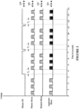
- a master device 102 goes into an alarm condition and drives the IO bus 118 high with a master IO signal 218.
- the master device 102 emits audible alert tone pulses 220 at defined time intervals, for example but not limited to, groups of three alert tone pulses at four (4) second cycles per the National Fire Protection Association (NFPA) 72: National Fire Alarm and Signaling Code.
- NFPA National Fire Protection Association
- At least one of the other devices 102 not necessarily in alarm, repeats the three alert tone pulses 222.
- Resulting apparent tone pulses 224 are shown having examples of various off synchronization phasing resulting in a jumble of confusing tones that do not clearly annunciate an alarm condition.
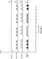
- a master device 102 goes into an alarm condition and drives the IO bus 118 high with a master IO signal 318 starting at time T 0 , and periodically goes low to provide a synchronization signal to all other devices 102 connected to the IO bus 118, as more fully described hereinafter.
- the master device 102 may emit audible alert tone pulses 320 at defined time intervals, for example but not limited to, groups of three alert tone pulses at four (4) second cycles per the National Fire Protection Association (NFPA) 72: National Fire Alarm and Signaling Code.
- NFPA National Fire Protection Association
- the start of a group of three tone pulses 320 may occur after a time, T 1 , from a positive going edge of the master IO signal 318, and thereafter be synchronized thereto.
- At least one of the other devices 102 may repeat with the three alert tone pulses 322 in synchronization with the positive going edges of the master IO signal 318.
- the resulting apparent tone pulses 324 are audibly reinforced from the synchronized tone pulses 320 and 322, thereby clearly annunciating an alarm condition.
- the remote devices 102 may synchronize to the rising edge of the master IO signal 318 with a delay of time T 1 before starting the remote horn alert tone pulses 322.
- the originating device 102 anticipates a delay for the master IO signal 318 such that timing for the originating (master) and remote alarm alert tone pulses 320 and 322 are substantially the same.
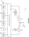
- FIG. 4 depicted is a schematic block diagram of a hazard detection and alarm signaling device shown in Figure 1 , according to a specific example embodiment of this disclosure.
- the hazard detection and alarm signaling device 102 is as described in Figure 1 hereinabove, wherein the IO bus driver 114 may have a constant current output determined by the constant current source 420, and is tri-stated such that its output may be placed in a high impedance state.
- a bus load resistor 422 acts as a soft pull-down when the IO bus driver 114 is in the high impedance output state.
- An output from the IO bus receiver 116 is coupled to a first input of the master/slave/follower processor 112 and a time delayed output from a time delay filter 424 is coupled to a second input of the master/slave/follower processor 112.
- the time delay filter 424 may be configured for, but is not limited to, a delay of 320 milliseconds plus or minus three (3) percent wherein pulses of 300 milliseconds or less are ignored, e.g., no output from the time delay filter 424. These two signals (outputs to B and C) may be used in combination to insure that false triggering of the plurality of hazard detection and alarm signaling devices 102 do not occur.
- the hazard detector 106 is coupled to an input of the master/slave/follower processor 112 and provides an output signal when a hazard is detected.
- the alarm alert generator 108 shown in Figure 1 may comprise a clock 426, audio tone generator 428, an audio tone pulse synchronization circuit 430 and an audio power amplifier 432 for driving the audible sound reproducer 110. Other combinations of circuit functions can be used for the alarm alert generator 108 as would be known to one having ordinary skill in electronic design and the benefit of this disclosure.
- the audio tone pulse synchronization circuit 430 may be controlled by the master/slave/follower processor 112, or may be part of it, to provide audible alert tone pulses 320 if a master device 102 detects an alarm condition, or to provide synchronized tone pulses 322, if a slave or follower device 102, based upon the rising positive edges of the master IO signal 318 (see Figure 3 ).
- the time delay filter 424 may be separate from or part of the master/slave/follower processor 112, and may be accomplished in hardware and/or software as would be known to one having ordinary skill in digital microcontroller design and having the benefit of this disclosure.
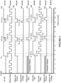
- FIG. 5 depicted are schematic timing diagrams of temporal audible alarm and control signals of the hazard detection and alarm signaling devices shown in Figures 1 and 4 , according to a specific example embodiment of this disclosure.
- a hazard detection and alarm signaling device 102 When a hazard detection and alarm signaling device 102 is first to go into a local alarm, e.g., local hazard detected by the hazard detector 106 of that device 102, it becomes the "master" device 102. Wherein audible alert tone pulses 320 begin issuing therefrom.
- a local alarm e.g., local hazard detected by the hazard detector 106 of that device 102
- audible alert tone pulses 320 begin issuing therefrom.
- the master device 102 After the first set of three pulses 320, the master device 102 asserts a signal 518 at a logic high, e.g., a voltage or current, positive or negative with reference to a zero voltage or current when no other master IO signal 518 has previously been asserted for a certain length of time, e.g ., seven (7) seconds.
- a first assertion of the master IO signal 518 occurs at time T 0 which is after the first set of audible alert tone pulses 320, and continues asserted until after the end of the next set of three audible alert tone pulses 320.
- the start of the next set of three audible alert tone pulses 320 occurs after time T 1 has elapsed.
- the master IO signal 518 is asserted at a logic low on the IO bus 118.
- the logic low thereon discharges any residual voltage or current on the IO bus 118 from the logic high previously thereon.
- a master IO high-drive is shown as signal 530 corresponds to logic highs asserted on the IO bus 118 by the master IO signal 518
- a master IO low dump is shown as signal 532 and corresponds to logic lows asserted on the IO bus 118 by the master IO signal 518 for residual voltage discharge therefrom.
- a master IO high impedance signal 534 is at a logic high which indicates that the IO bus 118 is in a "high impedance" state so that a Follower device 102 in alarm may become a Master if the present Master device 102 is no longer in an alarm condition.
- the master IO high impedance signal 540 represents when contention windows for the IO bus driver 114 of the present Master device 102 briefly goes into an off or high impedance output state for time T 4 .
- another Follower device 102 in alarm can attempt to "grab" the IO bus 118 and become a Master device 102, but only when there is no logic high asserted on the IO bus 118 for a certain time period, e.g., about seven (7) seconds.
- the Follower device 102 also has at least one contention window represented by the follower IO high drive signal 540.
- the follower IO high drive signal 540 also represents when a Follower device 102 is in alarm and tries to become a Master during a portion of the time T 6 .
- the time delay filter 424 is used to prevent unintended alarm actuation of Slave and/or Follower devices 102 from a logic high asserted on the IO bus 118 for less than a desired time period, e.g ., 320 milliseconds +/- three (3) percent, and that the time delay filter 424 will not operate, e.g ., assert a received logic high signal at input B of the processor 112 for an input from the IO bus 108 of less than a certain verification time period, e.g., about 300 milliseconds or less.
- a desired time period e.g 320 milliseconds +/- three (3) percent
- the Slave/Follower audible alert tone pulses 322 begin issuing therefrom after another time period T 3 has elapsed.
- T 1 is defined as being equal to the sum of T 2 and T 3 , even though the time delay filter introduces a delay time, e.g., time period T 2 , the audible alert tone pulses 320 and 322 will be synchronized and acoustically coherent.
- a Master is in local alarm and drive the IO bus 118 to a logic high
- a follower is in local alarm but does not drive the IO bus 118 to a logic high, rather it synchronizes to the positive edges of the signal 518 on the IO bus 118
- a Slave in remote alarm synchronizes to the positive edges of the signal 518 on the IO bus 118. All audible alert tone pulses 320 and 322 are thereby synchronized and acoustically coherent.
- a device is in remote alarm before going into local alarm, this device will now become a Follower instead of a Slave.
- the Master device 102 goes from the Master state to a Follower state.
- the follower state if the device is in the follower state and the IO bus 118 is low for longer than a certain time period, e.g., seven (7) seconds then the Follower becomes the Master of the IO bus 118.
- step 650 the IO bus 118 is monitored by each of the devices 102.
- step 652 determines whether a device 102 is in a local alarm. If not in a local alarm, then in step 664 the device 102 becomes/remains a Slave device. If the device is in a local alarm, then step 654 determines if a positive going logic level, e.g., logic low to logic high, is detected on the IO bus 118 (output of bus receiver 116).
- a positive going logic level e.g., logic low to logic high
- step 656 determines whether the logic high remains asserted on the IO bus 118 for a time T 2 (output of time delay filter 424). If the logic high does not remain asserted on the IO bus 118 for the time T 2 , then in step 660 the device 102 becomes an IO bus Master, and in step 662 the new IO bus Master asserts a logic high onto the IO bus 118. However, if a logic high on the IO bus 118 does remain for time T 2 , then in step 658 the device 102 becomes a Follower device.
- step 764 determines whether during a contention time window there is not a logic high present on the IO bus 108 for a contention window time.
- step 760 a previous Follower device 102 will become the Master device 102, and in step 762 the new Master device 102 will then assert a logic high on the IO bus 108 at the appropriate times for synchronizing the audible alert tone pulses 322 from the other Follower and Slave devices 102, as more fully described hereinabove.
- FIG. 8 depicted is a schematic process flow diagram for synchronizing alert tones from the Follower and Slave devices to the alert tones from the Master device, according to a specific example embodiment of this disclosure.
- the status of each of the devices 102 is determined, i . e ., which one of the devices 102 is the Master, and the other devices 102 are Followers and Slaves depending on whether they are also in local alarm or not, respectively.
- the Master yields to the other device 102 driving the IO bus 118 and assumes Follower status.
- Steps 650, 651 and 652 from Figure 6 are shown again for clarity.
- the logic in each device will wait a time T 3 before starting a three alert tone sequence in step 876.
Landscapes
- Physics & Mathematics (AREA)
- General Physics & Mathematics (AREA)
- Electromagnetism (AREA)
- Alarm Systems (AREA)
Claims (11)
- Gefährdungsdetektions- und Alarmvorrichtung, die aufweist:einen Gefährdungsdetektor (106), der ausgebildet ist, um ein Gefährdungsdetektionssignal zu erzeugen;einen Alarmwarnungsgenerator (108);ein Akustikschallwiedergabegerät (110), das einen von dem Alarmwarnungsgenerator (108) angetriebenen akustischen Alarm ausgibt,einen digitalen Prozessor (112), der einen ersten Eingang aufweist, der mit dem Gefährdungsdetektor (106) zum Empfangen des Gefährdungsdetektionssignals gekoppelt ist, und einen ersten Ausgang, der mit dem Alarmwarnungsgenerator (108) zu dessen Steuerung gekoppelt ist;einen Bustreiber (114), der einen Eingang aufweist, der mit einem zweiten Ausgang des digitalen Prozessors (112) gekoppelt ist, und einen Ausgang, der zur Kopplung mit einem Input-Output-Bus (118) geeignet ist, wobei der Bustreiber (114) ausgebildet ist, um einen ersten Ausgangszustand mit niedriger Impedanz, einen zweiten Ausgangszustand mit niedriger Impedanz und einen Ausgangszustand mit hoher Impedanz zu erzeugen, die an den Input-Output-Bus (118) angelegt werden, wobei die Auswahl der Ausgangszustände durch den digitalen Prozessor (112) in Abhängigkeit von einem Betriebszustand der Gefährdungsdetektions- und Alarmvorrichtung gesteuert wird;einen Busempfänger (116), der einen Eingang aufweist, der zum Koppeln mit dem Eingangs-Ausgangs-Bus (118) angepasst ist, und einen Ausgang, der mit einem zweiten Eingang des digitalen Prozessors (112) gekoppelt ist; undeinen Zeitverzögerungsfilter (424), der einen mit dem Ausgang des Busempfängers (116) gekoppelten Eingang und einen mit einem dritten Eingang des digitalen Prozessors (112) gekoppelten Ausgang aufweist, wobei der Zeitverzögerungsfilter (424) in Kombination mit dem am zweiten Eingang empfangenen Signal verwendet wird, um Impulse auf dem Input-Output-Bus (118) zu ignorieren, die eine Länge von weniger als einer vorgegebenen Periode aufweisen;wobei der digitale Prozessor aus dem Gefährdungsdetektionssignal und den vom Input-Output-Bus (118) über den Busempfänger (116) und den Zeitverzögerungsfilter (424) empfangenen Signalen feststellt, ob die Gefährdungsdetektions- und Alarmvorrichtung in einen Master-, Follower- oder Slave-Zustand geschaltet werden soll,wobei die Gefährdungsdetektions- und Alarmvorrichtung in einen Master-Zustand übergeht, wenn der digitale Prozessor (112) das Gefährdungsdetektionssignal vom Gefährdungsdetektor (106) empfängt, aber entweder keinen positiven logischen Pegel auf dem Input-Output-Bus (118) feststellt oder die Aktivierung eines logischen hohen Zustands kürzer als die Zeitspanne des Zeitverzögerungsfilters (424) bestehen bleibt, wobei die Vorrichtung, wenn sie in einen Master-Zustand übergeht, einen logischen hohen Zustand auf dem Input-Output-Bus (118) aktiviert, danach eine Reihe von ersten Alarmen durch das Akustikschallwiedergabegerät (110) erzeugt und danach die Gefährdungsdetektions- und Alarmvorrichtung periodisch eine Sequenz erzeugt, die a) einen logisch hohen Ausgangszustand auf dem Input-Output-Bus (118) aufweist, bis nach dem Ende von b) einer nächsten Reihe von akustischen Alarmtonimpulsen und danach auf dem Input-Output-Bus (118) c) eine erste vorgegebene Periode (T5) erzeugt, die einen logisch niedrigen Zustand aufweist, gefolgt von einem Contention-Zeitfenster (T4) des hochohmigen Ausgangszustands, während dessen eine Follower-Vorrichtung Master werden kann, wenn die Gefährdungsdetektions- und Alarmvorrichtung sich nicht mehr in einem Alarmzustand befindet,wobei die Gefährdungsdetektions- und Alarmvorrichtung zu einer Follower-Vorrichtung wird, wenn der digitale Prozessor der Gefährdungsdetektions- und Alarmvorrichtung ein lokales Gefährdungsdetektionssignal detektiert und die Gefährdungsdetektions- und Alarmvorrichtung die Aktivierung eines logisch hohen Zustands detektiert, der zumindest für die Zeitdauer des Zeitverzögerungsfilters (424) vorhanden bleibt;wobei die Vorrichtung im Follower-Zustand feststellt, ob während eines Contention-Fensters kein logisches Hoch auf dem Input-Output-Bus vorhanden ist, und wenn während der Zeit des Contention-Fensters kein logisches Hoch auf dem Input-Output-Bus vorhanden ist, die Follower-Vorrichtung, die sich immer noch in einem lokalen Alarmzustand befindet, in den Master-Zustand übergeht und die Aktivierung eines logischen Hochs auf dem Input-Output-Bus (118) übernimmt, wobei der Slave-Zustand einen Betriebszustand der Gefährdungsdetektions- und Alarmvorrichtung definiert, in dem die Gefährdungsdetektions- und Alarmvorrichtung kein Gefährdungsdetektionssignal von dem Gefährdungsmelder empfängt,wobei hörbare Alarmtonimpulse in dem Slave- oder Follower-Zustand nach einer zweiten vorgegebenen Zeitspanne (T3) ab dem Erfassen der Aktivierung des logisch hohen Zustands auf dem Input-Output-Bus (118) ausgegeben werden und die Zeitspanne den Zeitverzögerungsfilter (424), wobei die zweite vorgegebene Zeitspanne (T3) eine vorgegebene Länge aufweist, um die Alarmtonimpulse mit einer Master-Vorrichtung zu synchronisieren.
- Gefährdungsdetektions- und Alarmvorrichtung gemäß Anspruch 1, wobei der Alarmwarnungsgenerator (108) aufweist:einen Audiotongenerator (428)eine Audiotonimpuls-Synchronisationsschaltung (430), die einen mit dem Audiotongenerator (428) gekoppelten Eingang aufweist; undeinen Audio-Leistungsverstärker (432), der einen mit einem Ausgang der Audiotonimpuls-Synchronisationsschaltung (430) gekoppelten Eingang und einen mit dem Akustikschallwiedergabegerät (110) gekoppelten Ausgang aufweist;
- Gefährdungsdetektions- und Alarmvorrichtung gemäß Anspruch 1, wobei der Bustreiber (114) einen Konstantstromausgang aufweist, der von einer Konstantstromquelle (420) bestimmt wird.
- Gefährdungsdetektions- und Alarmvorrichtung gemäß Anspruch 1, die weiterhin einen Buslastwiderstand (422) aufweist, der zwischen Masse und dem Input-Output-Bus (118) gekoppelt ist und als weicher Pull-Down-Widerstand wirkt, wenn sich der Bustreiber (114) im Ausgangszustand mit hoher Impedanz befindet.
- Gefährdungsdetektions- und Alarmvorrichtung gemäß Anspruch 1, wobei der Zeitverzögerungsfilter (424) für eine Verzögerung von 320 Millisekunden plus oder minus drei (3) Prozent ausgebildet ist, wobei Impulse von 300 Millisekunden kein Ausgangssignal des Zeitverzögerungsfilters (424) erzeugen.
- Gefährdungsdetektions- und Alarmvorrichtung gemäß Anspruch 1, wobei eine Zeit, während der der digitale Prozessor (112) das Gefährdungsdetektionssignal vom Gefährdungsdetektor (106) empfängt, aber entweder keinen positiven logischen Pegel auf dem Input-Output-Bus (118) feststellt oder die Aktivierung eines logisch hohen Zustandes weniger als die Zeitdauer des Zeitverzögerungsfilters (424) vorhanden bleibt, sieben Sekunden lang ist.
- Gefährdungsdetektions- und Alarmvorrichtung gemäß Anspruch 2, wobei der Alarmwarnungsgenerator (108) weiterhin einen Taktgeber (426) aufweist, der mit dem digitalen Prozessor (112) und dem Audiotongenerator (428) gekoppelt ist.
- Gefährdungsdetektions- und Alarmvorrichtung gemäß Anspruch 2, wobei die Audiotonimpuls-Synchronisationsschaltung (430) Teil des digitalen Prozessors (112) ist.
- Gefährdungsdetektions- und Alarmvorrichtung gemäß Anspruch 1, wobei der Zeitverzögerungsfilter (424) Teil des digitalen Prozessors (112) ist.
- Gefährdungsdetektions- und Alarmvorrichtung gemäß einem der vorhergehenden Ansprüche, wobei der Gefährdungsdetektor (106) ausgebildet ist, um Rauch, Kohlenmonoxid, Radon, Chlor oder Feuchtigkeit zu erkennen.
- Gefährdungsdetektions- und Alarmvorrichtung gemäß einem der vorhergehenden Ansprüche, wobei der Input-Output-Bus als drahtloses Datennetzwerk, Bluetooth, Zigbee, WiFi, WLAN oder Netzanschluss-Trägerstrom implementiert ist.
Applications Claiming Priority (3)
| Application Number | Priority Date | Filing Date | Title |
|---|---|---|---|
| US201161558526P | 2011-11-11 | 2011-11-11 | |
| US13/478,486 US8922362B2 (en) | 2011-11-11 | 2012-05-23 | Temporal horn pattern synchronization |
| PCT/US2012/064105 WO2013070883A1 (en) | 2011-11-11 | 2012-11-08 | Temporal horn pattern synchronization |
Publications (2)
| Publication Number | Publication Date |
|---|---|
| EP2777029A1 EP2777029A1 (de) | 2014-09-17 |
| EP2777029B1 true EP2777029B1 (de) | 2025-01-22 |
Family
ID=48280036
Family Applications (1)
| Application Number | Title | Priority Date | Filing Date |
|---|---|---|---|
| EP12795937.7A Active EP2777029B1 (de) | 2011-11-11 | 2012-11-08 | Temporäre warnsignalmustersynchronisation |
Country Status (6)
| Country | Link |
|---|---|
| US (1) | US8922362B2 (de) |
| EP (1) | EP2777029B1 (de) |
| KR (1) | KR101961878B1 (de) |
| CN (1) | CN104054113B (de) |
| TW (1) | TWI584234B (de) |
| WO (1) | WO2013070883A1 (de) |
Families Citing this family (11)
| Publication number | Priority date | Publication date | Assignee | Title |
|---|---|---|---|---|
| US12301973B2 (en) * | 2012-09-17 | 2025-05-13 | Gregory Thomas Joao | Apparatus and method for providing a wireless, portable, and/or handheld, device with safety features |
| US9875644B2 (en) | 2014-09-09 | 2018-01-23 | Tyco Fire & Security Gmbh | Master slave wireless fire alarm and mass notification system |
| US12379217B2 (en) | 2014-11-30 | 2025-08-05 | Raymond Anthony Joao | Personal monitoring apparatus and method |
| US20160171858A1 (en) * | 2014-12-10 | 2016-06-16 | Jonas Patrik TRUMPHY | Alarm systems for detecting and communicating anomalous events |
| EP3035311B1 (de) | 2014-12-19 | 2019-10-09 | Novar GmbH | Bus-Mastervorrichtung für ein Gefahrenalarmsystem und Gefahrenalarmsystem damit |
| EP3539092B1 (de) * | 2016-11-08 | 2020-08-19 | Johnson Controls Fire Protection LP | Synchronisation von benachrichtigungsmustern in alarmierungssystemen |
| US10078943B2 (en) | 2016-11-08 | 2018-09-18 | Tyco Fire & Security Gmbh | Synchronization of notification patterns in alerting systems |
| CN109215273B (zh) * | 2018-09-06 | 2021-05-11 | 赛特威尔电子股份有限公司 | 一种火灾报警控制系统及方法 |
| US11765547B2 (en) | 2019-07-30 | 2023-09-19 | Raymond Anthony Joao | Personal monitoring apparatus and methods |
| US11775780B2 (en) | 2021-03-01 | 2023-10-03 | Raymond Anthony Joao | Personal monitoring apparatus and methods |
| US12556664B2 (en) | 2021-11-12 | 2026-02-17 | Raymond Anthony Joao | Personal monitoring apparatus and methods |
Citations (1)
| Publication number | Priority date | Publication date | Assignee | Title |
|---|---|---|---|---|
| US20020101344A1 (en) * | 2001-01-30 | 2002-08-01 | Tanguay William Peter | Apparatus and method for providing alarm syncrhonization among multiple alarm devices |
Family Cites Families (11)
| Publication number | Priority date | Publication date | Assignee | Title |
|---|---|---|---|---|
| US5598139A (en) * | 1993-09-30 | 1997-01-28 | Pittway Corporation | Fire detecting system with synchronized strobe lights |
| US6906616B1 (en) | 1995-03-20 | 2005-06-14 | Wheelock, Inc. | Apparatus and method for synchronizing visual/audible alarm units in an alarm system |
| US6897772B1 (en) * | 2000-11-14 | 2005-05-24 | Honeywell International, Inc. | Multi-function control system |
| US7075444B2 (en) | 2002-11-15 | 2006-07-11 | Maple Chase Company | Temporary alarm locate with intermittent warning |
| US7880604B2 (en) * | 2005-09-20 | 2011-02-01 | Selflink, Llc | Self-configuring emergency event alarm system with autonomous output devices |
| AU2006345218B2 (en) * | 2006-06-27 | 2011-03-17 | Tyco Fire & Security Gmbh | Wireless synchronized operation of pulsed EAS systems |
| US7893825B2 (en) | 2007-11-20 | 2011-02-22 | Universal Security Instruments, Inc. | Alarm origination latching system and method |
| AU2008332565B2 (en) | 2007-12-06 | 2012-07-19 | Hochiki Corporation | Alarm device and alarm system |
| CN101488265B (zh) * | 2008-01-14 | 2010-07-28 | 华为技术有限公司 | 语音告警系统及语音告警实现方法 |
| GB2457307A (en) | 2008-02-11 | 2009-08-12 | Apollo Fire Detectors Ltd | Fire alarm signalling with voice modulated HF signal multiplexed on to plateaus of existing lower frequency pulses carried on power cabling |
| TWI393085B (zh) * | 2009-05-22 | 2013-04-11 | Univ Kun Shan | Wireless sensor network system with synchronization warning function |
-
2012
- 2012-05-23 US US13/478,486 patent/US8922362B2/en active Active
- 2012-11-08 WO PCT/US2012/064105 patent/WO2013070883A1/en not_active Ceased
- 2012-11-08 EP EP12795937.7A patent/EP2777029B1/de active Active
- 2012-11-08 CN CN201280066369.1A patent/CN104054113B/zh active Active
- 2012-11-08 KR KR1020147015177A patent/KR101961878B1/ko active Active
- 2012-11-09 TW TW101141915A patent/TWI584234B/zh active
Patent Citations (1)
| Publication number | Priority date | Publication date | Assignee | Title |
|---|---|---|---|---|
| US20020101344A1 (en) * | 2001-01-30 | 2002-08-01 | Tanguay William Peter | Apparatus and method for providing alarm syncrhonization among multiple alarm devices |
Also Published As
| Publication number | Publication date |
|---|---|
| EP2777029A1 (de) | 2014-09-17 |
| CN104054113B (zh) | 2017-03-01 |
| TW201333894A (zh) | 2013-08-16 |
| TWI584234B (zh) | 2017-05-21 |
| KR101961878B1 (ko) | 2019-03-26 |
| US20130120136A1 (en) | 2013-05-16 |
| KR20140091037A (ko) | 2014-07-18 |
| CN104054113A (zh) | 2014-09-17 |
| US8922362B2 (en) | 2014-12-30 |
| WO2013070883A1 (en) | 2013-05-16 |
Similar Documents
| Publication | Publication Date | Title |
|---|---|---|
| EP2777029B1 (de) | Temporäre warnsignalmustersynchronisation | |
| EP2777030B1 (de) | Automatische tonalarmortung | |
| US9607494B2 (en) | Supervised interconnect smoke alarm system and method of using same | |
| CN101352051A (zh) | 在安全系统中产生语音警报信号的方法和装置 | |
| JP2008009480A (ja) | 無線により連動警報するワイヤレス型火災警報器、及びワイヤレス型火災警報システム | |
| JP2002074535A (ja) | 火災警報設備およびそれに利用する火災警報器 | |
| EP1356439B1 (de) | Vorrichtung und verfahren zur synchronisierung von mehreren alarmgeräten | |
| JP4713854B2 (ja) | 警報器 | |
| JP5122873B2 (ja) | 住宅用火災警報器 | |
| JP4710877B2 (ja) | 火災警報システム | |
| JP3957600B2 (ja) | 火災受信機 | |
| JPH1039016A (ja) | 超音波センサ | |
| JP5121855B2 (ja) | 警報器 | |
| JPH0135395B2 (de) | ||
| JP5123957B2 (ja) | 警報器 | |
| JP4873975B2 (ja) | 警報器 | |
| JP2004145464A (ja) | 火災受信機 | |
| JPS60220496A (ja) | 警報システムにおける異常検知方法 | |
| JPH06281746A (ja) | 物体検知システム |
Legal Events
| Date | Code | Title | Description |
|---|---|---|---|
| PUAI | Public reference made under article 153(3) epc to a published international application that has entered the european phase |
Free format text: ORIGINAL CODE: 0009012 |
|
| 17P | Request for examination filed |
Effective date: 20140610 |
|
| AK | Designated contracting states |
Kind code of ref document: A1 Designated state(s): AL AT BE BG CH CY CZ DE DK EE ES FI FR GB GR HR HU IE IS IT LI LT LU LV MC MK MT NL NO PL PT RO RS SE SI SK SM TR |
|
| DAX | Request for extension of the european patent (deleted) | ||
| 17Q | First examination report despatched |
Effective date: 20160406 |
|
| STAA | Information on the status of an ep patent application or granted ep patent |
Free format text: STATUS: EXAMINATION IS IN PROGRESS |
|
| GRAP | Despatch of communication of intention to grant a patent |
Free format text: ORIGINAL CODE: EPIDOSNIGR1 |
|
| STAA | Information on the status of an ep patent application or granted ep patent |
Free format text: STATUS: GRANT OF PATENT IS INTENDED |
|
| INTG | Intention to grant announced |
Effective date: 20240819 |
|
| GRAS | Grant fee paid |
Free format text: ORIGINAL CODE: EPIDOSNIGR3 |
|
| GRAA | (expected) grant |
Free format text: ORIGINAL CODE: 0009210 |
|
| STAA | Information on the status of an ep patent application or granted ep patent |
Free format text: STATUS: THE PATENT HAS BEEN GRANTED |
|
| AK | Designated contracting states |
Kind code of ref document: B1 Designated state(s): AL AT BE BG CH CY CZ DE DK EE ES FI FR GB GR HR HU IE IS IT LI LT LU LV MC MK MT NL NO PL PT RO RS SE SI SK SM TR |
|
| REG | Reference to a national code |
Ref country code: GB Ref legal event code: FG4D |
|
| REG | Reference to a national code |
Ref country code: CH Ref legal event code: EP |
|
| REG | Reference to a national code |
Ref country code: IE Ref legal event code: FG4D |
|
| REG | Reference to a national code |
Ref country code: DE Ref legal event code: R096 Ref document number: 602012081329 Country of ref document: DE |
|
| PG25 | Lapsed in a contracting state [announced via postgrant information from national office to epo] |
Ref country code: NL Free format text: LAPSE BECAUSE OF FAILURE TO SUBMIT A TRANSLATION OF THE DESCRIPTION OR TO PAY THE FEE WITHIN THE PRESCRIBED TIME-LIMIT Effective date: 20250122 |
|
| PG25 | Lapsed in a contracting state [announced via postgrant information from national office to epo] |
Ref country code: RS Free format text: LAPSE BECAUSE OF FAILURE TO SUBMIT A TRANSLATION OF THE DESCRIPTION OR TO PAY THE FEE WITHIN THE PRESCRIBED TIME-LIMIT Effective date: 20250422 |
|
| PG25 | Lapsed in a contracting state [announced via postgrant information from national office to epo] |
Ref country code: FI Free format text: LAPSE BECAUSE OF FAILURE TO SUBMIT A TRANSLATION OF THE DESCRIPTION OR TO PAY THE FEE WITHIN THE PRESCRIBED TIME-LIMIT Effective date: 20250122 |
|
| PG25 | Lapsed in a contracting state [announced via postgrant information from national office to epo] |
Ref country code: PL Free format text: LAPSE BECAUSE OF FAILURE TO SUBMIT A TRANSLATION OF THE DESCRIPTION OR TO PAY THE FEE WITHIN THE PRESCRIBED TIME-LIMIT Effective date: 20250122 |
|
| PG25 | Lapsed in a contracting state [announced via postgrant information from national office to epo] |
Ref country code: ES Free format text: LAPSE BECAUSE OF FAILURE TO SUBMIT A TRANSLATION OF THE DESCRIPTION OR TO PAY THE FEE WITHIN THE PRESCRIBED TIME-LIMIT Effective date: 20250122 |
|
| REG | Reference to a national code |
Ref country code: LT Ref legal event code: MG9D |
|
| PG25 | Lapsed in a contracting state [announced via postgrant information from national office to epo] |
Ref country code: IS Free format text: LAPSE BECAUSE OF FAILURE TO SUBMIT A TRANSLATION OF THE DESCRIPTION OR TO PAY THE FEE WITHIN THE PRESCRIBED TIME-LIMIT Effective date: 20250522 Ref country code: NO Free format text: LAPSE BECAUSE OF FAILURE TO SUBMIT A TRANSLATION OF THE DESCRIPTION OR TO PAY THE FEE WITHIN THE PRESCRIBED TIME-LIMIT Effective date: 20250422 |
|
| REG | Reference to a national code |
Ref country code: AT Ref legal event code: MK05 Ref document number: 1762046 Country of ref document: AT Kind code of ref document: T Effective date: 20250122 |
|
| PG25 | Lapsed in a contracting state [announced via postgrant information from national office to epo] |
Ref country code: HR Free format text: LAPSE BECAUSE OF FAILURE TO SUBMIT A TRANSLATION OF THE DESCRIPTION OR TO PAY THE FEE WITHIN THE PRESCRIBED TIME-LIMIT Effective date: 20250122 |
|
| PG25 | Lapsed in a contracting state [announced via postgrant information from national office to epo] |
Ref country code: LV Free format text: LAPSE BECAUSE OF FAILURE TO SUBMIT A TRANSLATION OF THE DESCRIPTION OR TO PAY THE FEE WITHIN THE PRESCRIBED TIME-LIMIT Effective date: 20250122 Ref country code: PT Free format text: LAPSE BECAUSE OF FAILURE TO SUBMIT A TRANSLATION OF THE DESCRIPTION OR TO PAY THE FEE WITHIN THE PRESCRIBED TIME-LIMIT Effective date: 20250522 |
|
| PG25 | Lapsed in a contracting state [announced via postgrant information from national office to epo] |
Ref country code: GR Free format text: LAPSE BECAUSE OF FAILURE TO SUBMIT A TRANSLATION OF THE DESCRIPTION OR TO PAY THE FEE WITHIN THE PRESCRIBED TIME-LIMIT Effective date: 20250423 Ref country code: BG Free format text: LAPSE BECAUSE OF FAILURE TO SUBMIT A TRANSLATION OF THE DESCRIPTION OR TO PAY THE FEE WITHIN THE PRESCRIBED TIME-LIMIT Effective date: 20250122 |
|
| PG25 | Lapsed in a contracting state [announced via postgrant information from national office to epo] |
Ref country code: AT Free format text: LAPSE BECAUSE OF FAILURE TO SUBMIT A TRANSLATION OF THE DESCRIPTION OR TO PAY THE FEE WITHIN THE PRESCRIBED TIME-LIMIT Effective date: 20250122 |
|
| PG25 | Lapsed in a contracting state [announced via postgrant information from national office to epo] |
Ref country code: SE Free format text: LAPSE BECAUSE OF FAILURE TO SUBMIT A TRANSLATION OF THE DESCRIPTION OR TO PAY THE FEE WITHIN THE PRESCRIBED TIME-LIMIT Effective date: 20250122 |
|
| PG25 | Lapsed in a contracting state [announced via postgrant information from national office to epo] |
Ref country code: SM Free format text: LAPSE BECAUSE OF FAILURE TO SUBMIT A TRANSLATION OF THE DESCRIPTION OR TO PAY THE FEE WITHIN THE PRESCRIBED TIME-LIMIT Effective date: 20250122 |
|
| PG25 | Lapsed in a contracting state [announced via postgrant information from national office to epo] |
Ref country code: DK Free format text: LAPSE BECAUSE OF FAILURE TO SUBMIT A TRANSLATION OF THE DESCRIPTION OR TO PAY THE FEE WITHIN THE PRESCRIBED TIME-LIMIT Effective date: 20250122 |
|
| PG25 | Lapsed in a contracting state [announced via postgrant information from national office to epo] |
Ref country code: IT Free format text: LAPSE BECAUSE OF FAILURE TO SUBMIT A TRANSLATION OF THE DESCRIPTION OR TO PAY THE FEE WITHIN THE PRESCRIBED TIME-LIMIT Effective date: 20250122 |
|
| PG25 | Lapsed in a contracting state [announced via postgrant information from national office to epo] |
Ref country code: EE Free format text: LAPSE BECAUSE OF FAILURE TO SUBMIT A TRANSLATION OF THE DESCRIPTION OR TO PAY THE FEE WITHIN THE PRESCRIBED TIME-LIMIT Effective date: 20250122 Ref country code: CZ Free format text: LAPSE BECAUSE OF FAILURE TO SUBMIT A TRANSLATION OF THE DESCRIPTION OR TO PAY THE FEE WITHIN THE PRESCRIBED TIME-LIMIT Effective date: 20250122 |
|
| REG | Reference to a national code |
Ref country code: DE Ref legal event code: R097 Ref document number: 602012081329 Country of ref document: DE |
|
| PG25 | Lapsed in a contracting state [announced via postgrant information from national office to epo] |
Ref country code: RO Free format text: LAPSE BECAUSE OF FAILURE TO SUBMIT A TRANSLATION OF THE DESCRIPTION OR TO PAY THE FEE WITHIN THE PRESCRIBED TIME-LIMIT Effective date: 20250122 |
|
| PG25 | Lapsed in a contracting state [announced via postgrant information from national office to epo] |
Ref country code: SK Free format text: LAPSE BECAUSE OF FAILURE TO SUBMIT A TRANSLATION OF THE DESCRIPTION OR TO PAY THE FEE WITHIN THE PRESCRIBED TIME-LIMIT Effective date: 20250122 |
|
| PLBE | No opposition filed within time limit |
Free format text: ORIGINAL CODE: 0009261 |
|
| STAA | Information on the status of an ep patent application or granted ep patent |
Free format text: STATUS: NO OPPOSITION FILED WITHIN TIME LIMIT |
|
| 26N | No opposition filed |
Effective date: 20251023 |
|
| PGFP | Annual fee paid to national office [announced via postgrant information from national office to epo] |
Ref country code: DE Payment date: 20251022 Year of fee payment: 14 |