EP2776983B1 - Rfid tag assembly - Google Patents
Rfid tag assembly Download PDFInfo
- Publication number
- EP2776983B1 EP2776983B1 EP11782607.3A EP11782607A EP2776983B1 EP 2776983 B1 EP2776983 B1 EP 2776983B1 EP 11782607 A EP11782607 A EP 11782607A EP 2776983 B1 EP2776983 B1 EP 2776983B1
- Authority
- EP
- European Patent Office
- Prior art keywords
- tag
- spacer
- assembly
- expandable
- bib
- Prior art date
- Legal status (The legal status is an assumption and is not a legal conclusion. Google has not performed a legal analysis and makes no representation as to the accuracy of the status listed.)
- Active
Links
Images


Classifications
-
- G—PHYSICS
- G06—COMPUTING OR CALCULATING; COUNTING
- G06K—GRAPHICAL DATA READING; PRESENTATION OF DATA; RECORD CARRIERS; HANDLING RECORD CARRIERS
- G06K19/00—Record carriers for use with machines and with at least a part designed to carry digital markings
- G06K19/06—Record carriers for use with machines and with at least a part designed to carry digital markings characterised by the kind of the digital marking, e.g. shape, nature, code
- G06K19/067—Record carriers with conductive marks, printed circuits or semiconductor circuit elements, e.g. credit or identity cards also with resonating or responding marks without active components
- G06K19/07—Record carriers with conductive marks, printed circuits or semiconductor circuit elements, e.g. credit or identity cards also with resonating or responding marks without active components with integrated circuit chips
- G06K19/077—Constructional details, e.g. mounting of circuits in the carrier
- G06K19/07749—Constructional details, e.g. mounting of circuits in the carrier the record carrier being capable of non-contact communication, e.g. constructional details of the antenna of a non-contact smart card
- G06K19/07758—Constructional details, e.g. mounting of circuits in the carrier the record carrier being capable of non-contact communication, e.g. constructional details of the antenna of a non-contact smart card arrangements for adhering the record carrier to further objects or living beings, functioning as an identification tag
- G06K19/07762—Constructional details, e.g. mounting of circuits in the carrier the record carrier being capable of non-contact communication, e.g. constructional details of the antenna of a non-contact smart card arrangements for adhering the record carrier to further objects or living beings, functioning as an identification tag the adhering arrangement making the record carrier wearable, e.g. having the form of a ring, watch, glove or bracelet
-
- G—PHYSICS
- G06—COMPUTING OR CALCULATING; COUNTING
- G06K—GRAPHICAL DATA READING; PRESENTATION OF DATA; RECORD CARRIERS; HANDLING RECORD CARRIERS
- G06K19/00—Record carriers for use with machines and with at least a part designed to carry digital markings
- G06K19/06—Record carriers for use with machines and with at least a part designed to carry digital markings characterised by the kind of the digital marking, e.g. shape, nature, code
- G06K19/067—Record carriers with conductive marks, printed circuits or semiconductor circuit elements, e.g. credit or identity cards also with resonating or responding marks without active components
- G06K19/07—Record carriers with conductive marks, printed circuits or semiconductor circuit elements, e.g. credit or identity cards also with resonating or responding marks without active components with integrated circuit chips
- G06K19/077—Constructional details, e.g. mounting of circuits in the carrier
- G06K19/07749—Constructional details, e.g. mounting of circuits in the carrier the record carrier being capable of non-contact communication, e.g. constructional details of the antenna of a non-contact smart card
- G06K19/07758—Constructional details, e.g. mounting of circuits in the carrier the record carrier being capable of non-contact communication, e.g. constructional details of the antenna of a non-contact smart card arrangements for adhering the record carrier to further objects or living beings, functioning as an identification tag
-
- G—PHYSICS
- G06—COMPUTING OR CALCULATING; COUNTING
- G06K—GRAPHICAL DATA READING; PRESENTATION OF DATA; RECORD CARRIERS; HANDLING RECORD CARRIERS
- G06K19/00—Record carriers for use with machines and with at least a part designed to carry digital markings
- G06K19/06—Record carriers for use with machines and with at least a part designed to carry digital markings characterised by the kind of the digital marking, e.g. shape, nature, code
- G06K19/067—Record carriers with conductive marks, printed circuits or semiconductor circuit elements, e.g. credit or identity cards also with resonating or responding marks without active components
- G06K19/07—Record carriers with conductive marks, printed circuits or semiconductor circuit elements, e.g. credit or identity cards also with resonating or responding marks without active components with integrated circuit chips
- G06K19/077—Constructional details, e.g. mounting of circuits in the carrier
- G06K19/07749—Constructional details, e.g. mounting of circuits in the carrier the record carrier being capable of non-contact communication, e.g. constructional details of the antenna of a non-contact smart card
- G06K19/07771—Constructional details, e.g. mounting of circuits in the carrier the record carrier being capable of non-contact communication, e.g. constructional details of the antenna of a non-contact smart card the record carrier comprising means for minimising adverse effects on the data communication capability of the record carrier, e.g. minimising Eddy currents induced in a proximate metal or otherwise electromagnetically interfering object
-
- H—ELECTRICITY
- H01—ELECTRIC ELEMENTS
- H01Q—ANTENNAS, i.e. RADIO AERIALS
- H01Q1/00—Details of, or arrangements associated with, antennas
- H01Q1/12—Supports; Mounting means
- H01Q1/22—Supports; Mounting means by structural association with other equipment or articles
- H01Q1/2208—Supports; Mounting means by structural association with other equipment or articles associated with components used in interrogation type services, i.e. in systems for information exchange between an interrogator/reader and a tag/transponder, e.g. in Radio Frequency Identification [RFID] systems
- H01Q1/2225—Supports; Mounting means by structural association with other equipment or articles associated with components used in interrogation type services, i.e. in systems for information exchange between an interrogator/reader and a tag/transponder, e.g. in Radio Frequency Identification [RFID] systems used in active tags, i.e. provided with its own power source or in passive tags, i.e. deriving power from RF signal
-
- H—ELECTRICITY
- H01—ELECTRIC ELEMENTS
- H01Q—ANTENNAS, i.e. RADIO AERIALS
- H01Q1/00—Details of, or arrangements associated with, antennas
- H01Q1/27—Adaptation for use in or on movable bodies
- H01Q1/273—Adaptation for carrying or wearing by persons or animals
Definitions
- the invention relates to a tag assembly, and, in particular, though not exclusively, to a tag assembly and a tag structure comprising an expandable spacer and a sports bib for use in such tag assembly.
- Radio Frequency Identification (RFID) tags are widely used for automatic time and/or location registration systems in sporting events.
- an RFID tag comprises a microchip combined with an antenna and is structured to allow attachment to an object to be detected.
- every participant is provided with an RFID tag, which is removable secured to a shoe or a bib comprising a number, which is associated with the name and/or address of the participant. If a participant crosses a detection antenna an electro-magnetical coupling between the tag and the antenna is established thereby allowing information exchange, e.g. an identify number associated with the tag, between the tag and a detector connected to the antenna.
- UHF ultra-high frequency
- tags are much cheaper (so that they can be used as a one-time use disposable tag), are less in weight, and can be read faster and from larger distances when compared with low frequency tags.
- tags are preferably distributed together with or attached to the bib so that there is an unambiguous one-to-one relation between the tag and the bib.
- the bib is fixed to the shirt such that the bib is located in front of the chest of the participant.
- Another problem relates to the fact that the tag is within close proximity of the body, which for the tag functions as a dielectric of relatively high dielectric constant.
- the proximity of the body changes the impedance of the tag antenna thereby "detuning" the tag away from its optimum working point. Due to this detuning effect, the tag may not able to generate detectable modulated backscatter signal.
- the effect of detuning is further enhanced in a wet environment, e.g. wet and sweaty clothing and/or body of an athlete. This way, the signal may further deteriorate thereby increasing the risk that a participant crossing or passing a detection antenna is not or at least not correctly registered by the timing system.
- a spacer in the vicinity of the tag may be used such that at least a certain distance between the tag and the wet clothes and/or body is provided.
- Such spacer may have the form of a strip of lightweight foam attached to or in the vicinity of the tag.
- Ideally such spacer should guarantee a spacing distance of about 10 mm, however such thickness makes such tag bib assemblies not suitable for mass distribution (by post) and storage (e.g. millions or more). Therefore, in practice, spacers are used which are thinner than the desirable optimal thickness. Hence, conventional spacers thus allow only suboptimal performance of the tag.
- US 2008/0018428 discloses a communication device that includes a radio frequency identification tag that performs a radio communication with a predetermined device.
- This communication device can be attached to goods or products stored in a warehouse or the like.
- a space adjustment unit which comprises a space adjustment screw and a spring, is configured to adjust a space between a metal plate and the radio frequency identification tag. This makes it possible to easily and effectively control the distance and the directivity of the radio communication.
- US 6,542,114 discloses a loader that can be used to load or unload a plane.
- the loader has a horizontal platform and has a powered scissors support for the platform which is capable of vertically raising and lowering the platform.
- the platform supports a pallet and the pallet in turn supports several items that each have a beacon tag on it.
- US 2007/0164866 discloses a security document having a contactless chip with data masking.
- the security document comprises a transponder connected to an antenna, serving to remotely communicate with a reader via an electromagnetic coupling, and a passive masking element of this antenna. This masking element is capable of rendering the reading of the document impossible when the security document is closed.
- a further problem associated with the use of a tag bib assembly is that the tag signal may be influenced by nearby objects. Especially when a lot of participants are crossing an antenna simultaneously, the presence of other persons in the direct proximity of the radiated signal may cause that only a very small part of the signal will be picked up by the detection antenna of the timing system. Hence, when using a tag bib assembly, it is desired that the tag signal is directed towards the detection antenna.
- US Patent 7,948,383 describes an RFID tag assembly for a shoe.
- the tag is removed from a bib and secured to a participant's shoe prior to a race. Attaching the RFID tag to the shoe requires multiple actions of the user. Improper installation of the tag to the shoe may result in a disfunctioning or even a non-functioning tag.
- the invention is defined by claim 1.
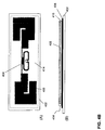
- FIG. 1A-1C schematically depict bib tag assemblies according to various embodiment of the invention.
- Fig. 1A and 1B depict the front and backside of a bib tag assembly for use e.g. in a sports event comprising a support sheet 102, e.g. a flexible, light-weight, water-resistant, sheet-like material that is adapted to be affixed to a person through the use of an adhesive or mechanism to pin or tie the support sheet to the person or animal (or clothing on the person or animal).
- exemplary materials used for support sheet include fabric, paper, woven sheet, plastic or any combination thereof.
- a front side of the support sheet may display an identifier such as an identifier 104 identifying the person to which the support sheet is affixed.
- Support sheet 102 may have a rectangular, 4-sided shape, but in other embodiment it may have any suitable shape, e.g., shape of a logo.
- Fig. 1B depicts the backside of the support sheet to which at least one tag 108 is affixed.
- the tag may comprise an antenna 106 for receiving and transmitting signals.
- the tag may relate to an UFH tag operating in the UHF frequency range.
- the tags or tag structures described below may be configured to operate in the frequency range between 800 and 1000 MHz.
- a tag may operate in a frequency range between 860 and 960 MHz.
- the tag may operate in a frequency range between 900 and 930 MHz.
- a tag may operate in a frequency range between 940 and 970 Mhz.
- the antenna associated with the tag may have a predetermined shape.
- the antenna may be a metallic (foldable and/or flexible) thin-film layer.
- the tag may have the form of a dipole antenna.
- the unfolded length of the tag may be approximately half the wavelength of the operation frequency, e.g. between 10-20 cm (900 MHz equals approximately 16 cm).
- the tag may further comprise a processor, i.e. an RFID-specific processor, for processing signals received by the tag.
- Tag 108 may be securely attached to support sheet 102 by means such as an adhesive or an adhesive layer. Depending on the application, the tag may be at least partly active and/or passive. In some embodiments, instead of the back-side, the tag may be affixed to the front-side of the bib.
- the bib tag assembly may further comprise an expandable spacer configured to create a spacing between the tag and the wet clothing and/or body of the participant.
- an expandable spacer refers to a spacer structure having an adjustable thickness or height or is able to have a particular range of thicknesses or heights.
- the expandable spacer may have a collapsed/compressed state with a small thickness or height, and an expanded state with a larger thickness or height.
- the spacer may have the form of one or more parts formed of expandable sheet material 110 1 located in the vicinity and/or (partly) on top of the tag/antenna structure 106,108.
- the expandable spacer may be configured such that when the bib tag assembly is not in use, (e.g. assembled for distribution to participants of an event), the spacer is in a collapsed (non-expanded) state. In that case, the spacer may be in the form of a thin flexible sheet or structure attached to the backside of the bib. In the non-expanded state, the spacer may have a thickness of approximately less than 3 millimetres, preferably less than 2 millimetres. This way, a bib tag assembly may be very thin so that easy distribution by post is possible.
- the material or structure when the expandable spacer is in its expanded state, may have a desired thickness so that is functions as a spacer for eliminating or at least decreasing detuning of the tag due to the close presence of the body of the wearer of the bib tag assembly. Desired thicknesses of the expandable spacer in expanded state may be between approximately 5 and 15 mm. For an UHF tag in use, the spacer may expand to a thickness of around 10 mm. In the expanded state, the spacer provides a desired distance between the tag and the wet shirt and/or body such that the negative influence of the wet shirt and/or body are considerably reduced.
- the tag/antenna structure may be attached to the bib such that its longitudinal axis is parallel to the ground surface.
- the tag signal may be picked up by a detection antenna, which is located on the ground (e.g. by use of an antenna mat) or above the athlete to be detected.
- the tag/antenna structure 106,108 and the associated expandable spacer structure 110 2 may be attached to the bib such that its longitudinal axis is perpendicular to the ground surface.
- the tag signal may be picked up by a detection antenna, which is located at at least one side of the athlete's path of travel.
- the expandable nature of the spacer may be achieved differently depending on the desired application.
- the expansion may be achieved by a material that expands in volume to a desired thickness.
- the spacer may be enabled by a mechanical structure that expands in size or enforces a certain distance/space between the bib and the body of the user wearing the bib when the structure is in its expanded state.
- the expandable spacer may expand in a self-acting manner which does not require no user interaction/configuration or in a manner that requires only little user action/configuration. Moreover, the expandable spacer is configured to expand to a desired height or thickness without the risk of improper expansion of the spacer due to human errors.
- the spacer preferably has collapsed state (i.e., reduced thickness) such that shipping large quantities of the bibs is practical. After shipping, the spacer may expand before the bib is attached to clothing/body, or during the use of the bib, e.g., during a race.
- a common material that is expandable is a porous material such as foam and sponge.
- Foam is capable of expanding in size when gas or moisture fills voids, holes or bubbles in the foam thereby enlarging the volume of the foam.
- An example of such foam is self-expanding foam used in insulation of homes or grow toys that expand in water.
- Sponge-like materials are capable of expanding in size when holes in the sponge absorbs moisture or take in air/gas.
- porous material Besides absorbing moisture to expand in size, some types of porous material expand and contract in size in response to pressure changes.
- a porous material that is packaged in a vacuum-sealed bag may be in a compressed form. If the vacuum-seal of the bag is broken, the porous material may expand by taking in air into the pores of the material.
- Various expandable spacer structures are described hereunder in more detail with reference to Fig. 3-8 .
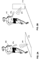
- Fig. 2A-2C depict a timing system for use with a bib tag assembly 202 according various embodiments of the invention.
- Fig. 2C depicts a schematic of a top-view of a timing system, which may comprise a detection antenna 208 connected to a decoder 206.
- the detection antenna may be configured as an elongated antenna mat placed on the ground, in the path of travel of the athletes, wherein the antenna mat may comprise one or more antennas configured to pick up signals transmitted by the bib-tag assembly.
- the detection antenna may be located at the side or above the path of travel of the athletes.
- different antenna implementations e.g. a patch antenna, a slot antenna or a yagi antenna, may be used.
- the tag may be configured as a passive backscatter system wherein the tag transmits a modulated signal 204 to the detection antenna. If a participant wearing a bib tag assembly 202 1-5 comes in the vicinity of the detection antenna, the tag antenna may receive the modulated signal 201, which is used to power-up the processor in the tag.
- Fig. 2A depicts e.g. an implementation wherein a detection antenna mat 210 transmits a modulated signal 201 in a direction opposite to the direction in which the athlete wearing the bib tag is moving.
- Fig. 2B depicts a detection antenna 210 located at a side of the athlete's path of travel wherein the detection antenna transmits a modulated signal towards on side of the athlete wearing a bib tag.
- the tag transmits information stored in the processor back to the detection antenna on the basis of a modulating back-scattered signal 203 1 .
- the tag may start sending out messages 203 1-4 comprising at least a unique ID identifying the bib.
- the detection antenna may pick up the transmitted messages and transfer them to the decoder, which comprises a processor for executing an algorithm 212 for determining the (spit) time associated with the tag on the basis of time of detection and the signal strength of the received ID messages.
- the processed data may be subsequently stored in a storage 214, e.g. a database, for further use.
- the decoder algorithm may determine the exact passing of a tag above the centre-line of the antenna mat. Determination of the time that the tag passes the centre-line requires measuring the signal strength of multiple messages originating from a tag. It is therefore very important that optimal signal transfer between the tag and the antenna mat is achieved. This may be achieved by bib tag assembly comprising an expandable spacer, which allows expansion to a desired optimum thickness.
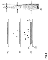
- Fig. 3A-3D depict an embodiment of an expandable tag spacer for use in a bib tag assembly according to an embodiment of the invention.
- Fig. 3A-3C depict at least part of a support sheet 302 to which a expandable sheet material 304 is attached to.
- the sheet material may comprise a thin sheet of water-expandable material.
- the water-expandable material may be a pressed sponge-like material, such as pressed celluloses, which absorbs water and/or moisture 306 by using capillary action to fill small holes in the interior of the sponge material.
- the material may be affixed to the backside of the bib and may have the form of strip in close vicinity and/or (partly) on top of the tag as illustrated.
- the sweat of the athlete will be partly absorbed by the water-absorbing material so that the material will start expanding as schematically indicated in Fig. 3A-3C .
- the expansion of the material is limited to one dimension (i.e. the z-dimension perpendicular to the x-y plane of the support sheet) in order to avoid the development of tension in the plane of the bib.
- the thickness of the water-expandable material in expanded state may be selected such that the spacer has a thickness of about 10 mm, i.e. a spacer thickness which allows good coupling between the tag backscatter signal and the detection antenna in the UHF frequency range.
- Fig. 3D depicts the effect of the expansion at various stages for a pressed cellulose material. This figure clearly shows that the thickness of the material in the expanded state may be easily 5-15 times the thickness of the material in the pressed state.
- water-expandable material is not limited to water-expandable material based on sponge-like materials such pressed celluloses, but may encompass any type of material, which provides considerable expansion in at least one dimension.
- the water-expandable material may be biodegradable.
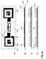
- Fig. 4A depicts expandable tag spacers according to various embodiments of the invention.
- Fig. 4A (A) and (B) depict top view and a side view of an embodiment wherein, the spacer may comprise several pieces of expandable sheet material which may be provided onto (or fixed to) the tag structure.
- the tag structure may include a processor such as an integrated circuit (IC) for receiving, processing and transmitting RFID signals 404 and the metallic thin-film antenna structure 406, which is provided onto a flexible support sheet 402.
- the processor and the metallic thin-film antenna structure may be covered with a passivation layer (not shown), e.g. a thin-film insulating layer.
- the backside of the support sheet may comprise an adhesive such that the tag structure may be attached as a sticker to a bib.
- Pieces of the expandable sheet material 408 1-23 forming an expandable spacer structure may be attached to the front side of the tag structure.
- the expandable spacer structure may comprise e.g. two pieces of expandable material 408 1,2 provided the tag structure area comprising the antenna structures and at least one piece of expandable material 408 3 provided over the area comprising the tag processor.
- Fig. 4A (C) depicts a side view of the tag structure wherein the expandable spacer is in its expanded state.
- tagstructures may be provisioned with an expandable spacer structure during manufacturing of the tag structure.
- the tag structure may be provided with a expandable spacer structure in a post-processing step after manufacturing of the tag structure.
- Fig. 4A(D) depicts a further embodiment, wherein the tag structure comprises an expandable spacer structure 410 1,2 (e.g. two or more pieces of water-expandable sheet material similar to the ones described with reference to Fig. 4A (A)-(C) and a fixed spacer structure 412 of a predetermined thickness.
- the fixed spacer structure may have a thickness of about 2-6 mm and functions as a spacer structure for the time that the expandable structure has not expanded to its full height (e.g. at the beginning/start of the race when the athletes are not yet sufficiently sweating in order to active that expandable spacer structures.
- Fig. 4B depict top view and side view of a tag structure according to various other embodiments of the invention.
- the tag structure may comprises a processor 404 and a metallic thin-film antenna structure 406 provided onto a flexible support sheet 402.
- the processor and the metallic thin-film antenna structure may be protected by a (thin-film) passivation layer.
- An expandable spacer structure 414 is disposed onto at least part of the antenna and processor area of the tag structure.
- the expandable spacer structure may have a multilayered structure comprising at least an expandable sheet material 408 and one or more dielectric layers 416 .
- Fig. 4B (B) depicts a side-view of an expandable spacer structure comprising an expandable sheet material 408 and at least one layer of a dielectric having a relatively high dielectric constant 416.
- the antenna structure of the tag may be impedance matched (i.e. tuned) to the tag processor taking into account the presence of the thin film dielectric layer of relatively high dielectric constant between 10 and 50 in the direct proximity of said antenna structure.
- a dielectric layer may partially "screen" the proximity of the body.
- the layer may have a thickness of between 0.05 and 5 mm.
- the layer may comprise titanium dioxide.
- the layer may be formed of a polymer comprising titanium dioxide particles as a filler in order to increase the dielectric constant of the layer to a desired value.
- the dielectric layer 416 may comprise multiple dielectric layers, for example a first dielectric layer of a relatively low dielectric constant (e.g. between 1 and 5) at the interface with the tag structure and a second dielectric layer of a relatively high dielectric constant (between 10-50) on top of the first thin-film dielectric layer at the interface with the expandable spacer layer 408.
- a first dielectric layer of a relatively low dielectric constant e.g. between 1 and 5
- a second dielectric layer of a relatively high dielectric constant between 10-50
- the dielectric layers may formed on the basis of a polymer comprising one or more dielectric fillers (e.g. titanium dioxide, silicon dioxide, aluminium dioxide, aluminosilicates, etc.) in order to form a dielectric layer of a desired dielectric constant.
- the dielectric constant of such layer may be controlled by controlling the composition and/or concentration of the dielectric fillers (mixture) in the polymer carrier layer.
- the expandable spacer for use in a bib tag provides a simple and very cost efficient way of providing a desirable distance between the body and the tag.
- the spacer is activated when the body starts to sweat.
- the water-expandable material may come in very thin flexible sheets, it does not affect the thickness of the bib tag assembly when it is stored or distributed to users. Moreover, no human intervention is needed to activate the spacer.
- Fig. 4A and 4B it is submitted that the disclosure is not limited to the examples of Fig. 4A and 4B but also encompasses many different layouts and (multi-layered structures).
- the layered expandable spacer structures described with reference to Fig. 4B may be implemented in a accordance with one of the possible layouts as described with reference to Fig. 4A .
- Fig. 5A-5C depict schematics of an expandable spacer structure according to another embodiment of the invention.
- Support sheet 514 is shown in Fig. 5A-5C with an expandable spacer having several parts.
- the spacer has cover 524 (or wrapping material) that is adapted to vacuum-seal and compress expandable material 522. While cover 524 maintains a vacuum-sealed state, expandable material 522 is in a compressed state having a reduced height/thickness. The compressed state facilitates shipping and storage of said assembly.
- Vacuum-seal cover 516 may be a tape-like material that adheres (e.g., removably attached) to cover 524 to keep hole 520 sealed (see FIG. 5B ).
- the thickness of the expandable material may be selected such that the spacer has a thickness in a range between 5 and 15 mm.
- Vacuum-seal cover 516 may be part of a top sheet 512. Alternatively, vacuum-seal cover 516 may be securely attached to top sheet 512. In embodiments where a top sheet is used, when top sheet 512 (and vacuum-seal cover 516 ) is pulled away from support sheet 514, hole 520 is exposed thus breaking the vacuum-seal. Top sheet 512 may be joined with support sheet 514 at an edge. Alternatively, top sheet 512 may be a portion of a folded support sheet 514.
- the backside of the expandable spacer structure may comprise an adhesive such that it may be fixed to the backside of a bib like a sticker.
- a bib tag assembly as e.g. described with reference to Fig. 1 may be provided with such expandable spacer structure. When affixing the bib tag assembly to a shirt, the user only needs to break the vacuum-seal in order to bring the spacer structure into its expanded state.
- Fig. 6A-6C depict schematics of an expandable spacer structure according to yet another embodiment of the invention.
- a cover providing pressure onto an expandable material resulting in a compressed state of the expandable material
- the expandable material expands to the desired thickness in order to function as a spacer for a bib tag assembly.
- Exemplary compression means is shown as cover 608 having at least two portions 604, 606 that enables cover 608 to firmly and tightly compress expandable material 610, e.g. a foam sheet, to supporting sheet 602.
- Cover 608 firmly applies pressure to expandable material 610 and may be removably attached to support sheet 602 at portion 604 and/or 606. When cover 608 is removed or opened, the compressed material expands in thickness/height to serve as a spacer, as seen in Fig. 6C .
- the backside of the expandable spacer structure may comprise an adhesive such that it may be fixed to the backside of a bib like a sticker.
- a bib tag assembly as e.g. described with reference to Fig. 1 may be provided with such expandable spacer structure. When affixing the bib tag assembly to a shirt, the user only needs to remove the cover in order to bring the spacer structure into its expanded state.
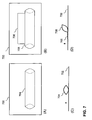
- Fig. 7A-7B depict schematics of an expandable spacer structure according to yet another embodiment of the invention.
- mechanical means for an expandable spacer may be used to create the desired space between the support sheet (as well as the tag) and the body.
- one side of carton 704 is used as a spacer, and said carton is firmly affixed to supporting sheet 702.
- Said carton is preferably made of a semi-rigid material that is capable of holding shape and structure in its expanded form.
- FIG. 7B compressed state
- Fig. 7D expanded state
- spacer comprises expandable portion 708 and fixed portion 706, where fixed portion 706 is firmly affixed to supporting sheet 702.
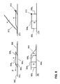
- Fig. 8A-8D depict schematics of an expandable spacer structure according to various other embodiments of the invention.
- mechanically foldable structures fixed to a support sheet 802 e.g. a bib, are used as expandable spacer.
- These spacer structures may have a folded state ( Fig. 8A and 8C ) and an expanded state ( Fig. 8B and 8D ).
- the spacer structure may comprise first and second support members 804 1,2 and first and second side members 806 1,2 , which are pivotably connected to the support members.
- the structure may be made of carton or another suitable material that has sufficient mechanical strength to serve as a reliable spacer in its expanded (erected) state.
- the spacer when folded the support and side members substantially parallel to the support sheet.
- the spacer may be erected by a user by a pulling force F parallel to the support sheet. Due to the force, the side members are erected in a position substantially perpendicular to the support member thereby creating a desired spacing S between first and second members.
- a simple fixation mechanism e.g. a latch 808, may be used to fixate the structure so to keep the structure in its expanded (erected) state.
- the folded mechanical spacer structure may be configured such that at least part of the pivotable connections between the support and side members is configured to provide a spring force 810, forcing the spacer structure to be in its erected state.
- a cover 812 may firmly applies pressure to the mechanically expandable spacer structure and may be removably attached to support sheet.
- the spring force will cause the structure to go to its erected state (similar to the situation as described with reference to Fig. 6 .
- an inflatable air pouches may also be used as a spacer.
- a pouch may be self-inflating or manually-inflatable by blowing air into the pouch.
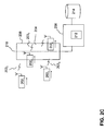
- Fig. 9A-9C depict schematics of a bib tag assembly according to further embodiments of the invention.
- efficient coupling between the tag and the antenna is desired when the athlete approaches the antenna.
- only a small part of the signal may be picked up by the antenna.
- the tag assembly may comprise a bib 902 comprising a tag 904 and an expandable spacer structure 906 1 (this spacer structure may be implemented in accordance with one of the embodiment as described with reference to Fig.
- the desired signal focussing direction 912 is in the direction of the antenna mat 914, i.e. downwardly, right in front of the participant wearing the bib tag assembly.
- the tag may comprise a dipole antenna of an elongated shape.
- the length is approximately half the wavelength of the operation frequency.
- the antenna signal may be read by an antenna which is positioned in front, above or under the athlete.
- a conductive passive element 908, e.g. a conductive strip or wire of length L, which is longer than the (effective) length of the tag and which is positioned at a certain distance above the tag may function as a reflector. In that case, if a tag transmits a message (e.g.
- a backscattered modulated signal to the antenna mat, part of the signal that is transmitted in a direction away from the antenna mat is reflected back towards the mat antenna, thereby effectively providing means for directing a larger part of the transmitted signal in a particular direction. This way the signal strength of the transmitted message is enhanced and the chance that the message is detected becomes larger.
- the reflector may have a length L selected within a range between 100 and 300 mm, preferably 150 and 250 mm, wherein the length of the reflector is longer than the (effective) length of the tag.
- the width W of the reflector may be within a range between approximately 1 to 25 mm.
- the distance D between the reflector and the tag may be selected between 50 and 100 mm.
- the tag may be operated in the UHF range, preferably at a frequency of 865 MHz or 915 MHz.
- the reflector may have the form of a conductive thin-film sheet fixed to the bib.
- Conductive materials may include aluminium, copper, conductive polymers and/or inks known in the art.
- the reflector may be in the shape of a conductive wire, which is fixed to or integrated into the bib material.
- a conductive ink or a moist sponge material may be used to form a conductive reflector pattern onto the bib.
- a nett gain of approximately 6 dB may be achieved. This allows an increase of the reading distance between a tag and the antenna mat of approximately 30-35%.
- further improvement in the tag signal may be achieved using a battery-assisted tag. In that case, a very thin battery in the tag may provide power to feed the IC of the tag.
- the bib-tag assembly in Fig. 9B comprises further passive elements 910 1,2 which are positioned under the tag. These conductive passive elements may be positioned substantially parallel to the tag and have a length which is smaller than the tag length. These passive elements, which are referred to as directors, may help to focus the transmitted in a downward direction. Typically, one or multiple directors may be used. The further a director is position from the tag, the short the length of the director (see e.g. Fig. 9B wherein director 910 2 is shorter than director 910 1 ).
- the bib-tag assemblies in Fig. 9A and 9B may further comprise expandable spacer structures 906 2 ,906 3 onto and/or within the direct proximity of the reflector and/or director structures such that these passive structures are not or at least less negatively influenced by the direct proximity of the (wet) body of the wearer of the bib-tag assembly.
- the invention is not limited to the use in sporting events and may also be applied in other areas, e.g. tag for use with animals.
Landscapes
- Engineering & Computer Science (AREA)
- Physics & Mathematics (AREA)
- Computer Hardware Design (AREA)
- Microelectronics & Electronic Packaging (AREA)
- General Physics & Mathematics (AREA)
- Theoretical Computer Science (AREA)
- Electromagnetism (AREA)
- Details Of Aerials (AREA)
- Burglar Alarm Systems (AREA)
- Professional, Industrial, Or Sporting Protective Garments (AREA)
- Details Of Garments (AREA)
Priority Applications (4)
| Application Number | Priority Date | Filing Date | Title |
|---|---|---|---|
| PL16170864T PL3086263T3 (pl) | 2011-11-10 | 2011-11-10 | Zespół znacznika RFID |
| DK16170864.9T DK3086263T3 (da) | 2011-11-10 | 2011-11-10 | RFID-brikmontage |
| EP16170864.9A EP3086263B1 (en) | 2011-11-10 | 2011-11-10 | Rfid tag assembly |
| CY20191100494T CY1121676T1 (el) | 2011-11-10 | 2019-05-08 | Συνολο ετικετας rfid |
Applications Claiming Priority (1)
| Application Number | Priority Date | Filing Date | Title |
|---|---|---|---|
| PCT/EP2011/069874 WO2013068043A1 (en) | 2011-11-10 | 2011-11-10 | Tag assembly |
Related Child Applications (2)
| Application Number | Title | Priority Date | Filing Date |
|---|---|---|---|
| EP16170864.9A Division-Into EP3086263B1 (en) | 2011-11-10 | 2011-11-10 | Rfid tag assembly |
| EP16170864.9A Division EP3086263B1 (en) | 2011-11-10 | 2011-11-10 | Rfid tag assembly |
Publications (2)
| Publication Number | Publication Date |
|---|---|
| EP2776983A1 EP2776983A1 (en) | 2014-09-17 |
| EP2776983B1 true EP2776983B1 (en) | 2016-06-29 |
Family
ID=44983529
Family Applications (2)
| Application Number | Title | Priority Date | Filing Date |
|---|---|---|---|
| EP11782607.3A Active EP2776983B1 (en) | 2011-11-10 | 2011-11-10 | Rfid tag assembly |
| EP16170864.9A Active EP3086263B1 (en) | 2011-11-10 | 2011-11-10 | Rfid tag assembly |
Family Applications After (1)
| Application Number | Title | Priority Date | Filing Date |
|---|---|---|---|
| EP16170864.9A Active EP3086263B1 (en) | 2011-11-10 | 2011-11-10 | Rfid tag assembly |
Country Status (19)
| Country | Link |
|---|---|
| US (2) | US10163054B2 (da) |
| EP (2) | EP2776983B1 (da) |
| JP (1) | JP5972388B2 (da) |
| CN (1) | CN104221038B (da) |
| AU (1) | AU2011380599B2 (da) |
| CY (1) | CY1121676T1 (da) |
| DK (1) | DK3086263T3 (da) |
| ES (2) | ES2591155T3 (da) |
| HR (1) | HRP20190614T1 (da) |
| HU (1) | HUE043484T2 (da) |
| IN (1) | IN2014CN03624A (da) |
| LT (1) | LT3086263T (da) |
| NZ (1) | NZ624796A (da) |
| PL (1) | PL3086263T3 (da) |
| PT (1) | PT3086263T (da) |
| RS (1) | RS58779B1 (da) |
| SI (1) | SI3086263T1 (da) |
| TW (1) | TW201342249A (da) |
| WO (1) | WO2013068043A1 (da) |
Families Citing this family (24)
| Publication number | Priority date | Publication date | Assignee | Title |
|---|---|---|---|---|
| EP2776983B1 (en) | 2011-11-10 | 2016-06-29 | AMB i.t. Holding B.V. | Rfid tag assembly |
| GB2516005A (en) * | 2013-05-24 | 2015-01-14 | Trm Trading Uk Ltd | Associating devices to participants |
| US10671820B2 (en) | 2013-10-13 | 2020-06-02 | Mylaps B.V. | Wearable sports timing tag assembly |
| US10062958B2 (en) * | 2014-11-21 | 2018-08-28 | Qualcomm Incorporated | Wearable electronic patch with antenna enhancement |
| GB201500509D0 (en) * | 2015-01-13 | 2015-02-25 | Roxan Developments Ltd | Antenna for identification tag and identification tag with antenna |
| US9965658B2 (en) | 2015-06-16 | 2018-05-08 | Motorola Mobility Llc | Person-centric activation of radio frequency identification (RFID) tag |
| JP2016149146A (ja) * | 2016-03-23 | 2016-08-18 | エーエムビー アイ.ティー.ホールディング ビーブイ | タグアセンブリ、タグ構造体及びスポーツ用ビブ |
| WO2017205619A1 (en) * | 2016-05-27 | 2017-11-30 | Berntsen International, Inc. | Uhf rfid tag for marking underground assets and locations and methods of using same |
| US10217042B2 (en) | 2016-11-23 | 2019-02-26 | Motorola Mobility Llc | RFID tags in wearables |
| US10975509B2 (en) | 2016-11-23 | 2021-04-13 | Motorola Mobility Llc | RFID-tagged textile article cleaning |
| JP6985800B2 (ja) * | 2017-02-08 | 2021-12-22 | マイラップス ビーブイ | 計時システム用の縦向きアンテナ構造体 |
| US10396442B2 (en) * | 2017-11-28 | 2019-08-27 | Starkey Laboratories, Inc. | Ear-worn electronic device incorporating combined dipole and loop antenna |
| US10685276B2 (en) | 2018-04-17 | 2020-06-16 | Miller Products, Inc. | Method of manufacturing a race bib |
| US10607127B2 (en) * | 2018-04-17 | 2020-03-31 | Miller Products, Inc. | Race bib |
| CN108828514A (zh) * | 2018-05-30 | 2018-11-16 | 娄书杰 | 可穿戴的2米波段无线电测向天线 |
| CA3105084A1 (en) * | 2020-01-06 | 2021-07-06 | bigDAWGS Promotions Inc. | Nfc enabled button |
| IT202000013294A1 (it) * | 2020-06-04 | 2021-12-04 | Datamars Sa | Metodo di produzione di un marcatore per un tessuto |
| SE2051510A1 (en) * | 2020-12-21 | 2022-06-22 | Digital Tags Finland Oy | Liquid detection rfid tag arrangement |
| AU2023207052A1 (en) | 2022-01-17 | 2024-08-01 | Mylaps B.V. | Uhf sports timing tag assembly |
| WO2026043592A1 (en) * | 2024-08-19 | 2026-02-26 | Sensormatic Electronics, LLC | Multi-layer radio frequency identification label and method of making same |
| USD1119875S1 (en) | 2024-12-20 | 2026-03-24 | Avery Dennison Retail Information Services Llc | Antenna |
| USD1119877S1 (en) | 2024-12-20 | 2026-03-24 | Avery Dennison Retail Information Services Llc | Antenna |
| USD1119876S1 (en) | 2024-12-20 | 2026-03-24 | Avery Dennison Retail Information Services Llc | Antenna |
| USD1119874S1 (en) | 2024-12-20 | 2026-03-24 | Avery Dennison Retail Information Services Llc | Antenna |
Family Cites Families (31)
| Publication number | Priority date | Publication date | Assignee | Title |
|---|---|---|---|---|
| US4318420A (en) * | 1979-10-04 | 1982-03-09 | T. K. Valve Limited | Ball valves |
| IT1231881B (it) * | 1989-03-16 | 1992-01-14 | Faricerca Spa | Elemento assorbente perfezionato e articolo assorbente comprendente tale elemento |
| US5497140A (en) * | 1992-08-12 | 1996-03-05 | Micron Technology, Inc. | Electrically powered postage stamp or mailing or shipping label operative with radio frequency (RF) communication |
| WO2000021031A1 (en) * | 1998-10-06 | 2000-04-13 | Intermec Ip Corp. | Rfid tag having dipole over ground plane antenna |
| US6147604A (en) * | 1998-10-15 | 2000-11-14 | Intermec Ip Corporation | Wireless memory device |
| US7945322B2 (en) * | 2005-11-11 | 2011-05-17 | Greatbatch Ltd. | Tank filters placed in series with the lead wires or circuits of active medical devices to enhance MRI compatibility |
| US6262692B1 (en) * | 1999-01-13 | 2001-07-17 | Brady Worldwide, Inc. | Laminate RFID label and method of manufacture |
| WO2001037215A1 (de) * | 1999-11-18 | 2001-05-25 | Siemens Aktiengesellschaft | Mobiler datenträger mit einem transponder aus einem oberflächenwellenbauelement mit schlitzantenne |
| US6542114B1 (en) * | 2000-09-07 | 2003-04-01 | Savi Technology, Inc. | Method and apparatus for tracking items using dual frequency tags |
| US6486783B1 (en) | 2000-09-19 | 2002-11-26 | Moore North America, Inc. | RFID composite for mounting on or adjacent metal objects |
| US20030114818A1 (en) * | 2001-08-03 | 2003-06-19 | Benecke Herman P. | Color masking component for use with feminine sanitary pad and the like |
| FR2863748B1 (fr) | 2003-12-12 | 2006-02-24 | Thales Sa | Document securise a puce sans contact avec masquage des donnees |
| JP4490242B2 (ja) | 2004-11-22 | 2010-06-23 | トッパン・フォームズ株式会社 | Icタグ収納ラベル |
| WO2006075398A1 (ja) * | 2005-01-17 | 2006-07-20 | Fujitsu Limited | 通信装置および通信方法 |
| CA2539994A1 (en) * | 2005-03-22 | 2006-09-22 | Laser Registration Lri Inc. | Identification badges with rfid tags and methods thereof |
| US20110024181A1 (en) * | 2005-04-01 | 2011-02-03 | Simon Phillips | System and method for protection against skimming of information from contactless cards |
| US8159349B2 (en) * | 2005-08-19 | 2012-04-17 | Adasa Inc. | Secure modular applicators to commission wireless sensors |
| JP2007066048A (ja) | 2005-08-31 | 2007-03-15 | Konica Minolta Photo Imaging Inc | Icカード |
| US7268725B2 (en) * | 2005-09-15 | 2007-09-11 | Honeywell International Inc. | Radar scan conversion for plan position indicator |
| US20110233281A1 (en) * | 2010-03-26 | 2011-09-29 | Howell Daniel R | Race bib timing device |
| JP5086004B2 (ja) | 2007-08-30 | 2012-11-28 | 富士通株式会社 | タグアンテナ、およびタグ |
| US8289165B2 (en) * | 2008-06-11 | 2012-10-16 | Avery Dennison Corporation | RFID device with conductive loop shield |
| US7948383B2 (en) | 2008-06-11 | 2011-05-24 | Miller Products, Inc. | RFID tag assembly and method of managing a race |
| JP2010079801A (ja) | 2008-09-29 | 2010-04-08 | Brother Ind Ltd | 無線タグラベル |
| JP2010086196A (ja) | 2008-09-30 | 2010-04-15 | Brother Ind Ltd | 無線タグ構造体、無線タグラベル、タグテープ、及び無線タグカートリッジ |
| JP5269690B2 (ja) | 2009-05-08 | 2013-08-21 | 小林クリエイト株式会社 | Rfidタグ |
| JP2010262540A (ja) | 2009-05-08 | 2010-11-18 | Kobayashi Create Co Ltd | Rfidタグ |
| US8576051B2 (en) * | 2010-01-29 | 2013-11-05 | Innovative Timing Systems, LLC. | Spaced apart extended range RFID tag assemblies and methods of operation |
| JP2011159212A (ja) | 2010-02-03 | 2011-08-18 | Toppan Forms Co Ltd | 非接触型データ受送信体およびこれを用いた重量物検知装置 |
| JP2012008682A (ja) * | 2010-06-23 | 2012-01-12 | Fujitsu Ltd | 無線タグ、および無線タグの製造方法 |
| EP2776983B1 (en) | 2011-11-10 | 2016-06-29 | AMB i.t. Holding B.V. | Rfid tag assembly |
-
2011
- 2011-11-10 EP EP11782607.3A patent/EP2776983B1/en active Active
- 2011-11-10 CN CN201180076251.2A patent/CN104221038B/zh active Active
- 2011-11-10 PT PT16170864T patent/PT3086263T/pt unknown
- 2011-11-10 HU HUE16170864A patent/HUE043484T2/hu unknown
- 2011-11-10 WO PCT/EP2011/069874 patent/WO2013068043A1/en not_active Ceased
- 2011-11-10 NZ NZ624796A patent/NZ624796A/en unknown
- 2011-11-10 US US14/357,674 patent/US10163054B2/en active Active
- 2011-11-10 EP EP16170864.9A patent/EP3086263B1/en active Active
- 2011-11-10 SI SI201131734T patent/SI3086263T1/sl unknown
- 2011-11-10 IN IN3624CHN2014 patent/IN2014CN03624A/en unknown
- 2011-11-10 DK DK16170864.9T patent/DK3086263T3/da active
- 2011-11-10 RS RS20190661A patent/RS58779B1/sr unknown
- 2011-11-10 ES ES11782607.3T patent/ES2591155T3/es active Active
- 2011-11-10 AU AU2011380599A patent/AU2011380599B2/en active Active
- 2011-11-10 JP JP2014540325A patent/JP5972388B2/ja active Active
- 2011-11-10 ES ES16170864T patent/ES2727966T3/es active Active
- 2011-11-10 LT LTEP16170864.9T patent/LT3086263T/lt unknown
- 2011-11-10 PL PL16170864T patent/PL3086263T3/pl unknown
-
2012
- 2012-11-09 TW TW101141968A patent/TW201342249A/zh unknown
-
2018
- 2018-11-02 US US16/179,507 patent/US11037043B2/en active Active
-
2019
- 2019-03-29 HR HRP20190614TT patent/HRP20190614T1/hr unknown
- 2019-05-08 CY CY20191100494T patent/CY1121676T1/el unknown
Non-Patent Citations (1)
| Title |
|---|
| None * |
Also Published As
| Publication number | Publication date |
|---|---|
| ES2727966T3 (es) | 2019-10-21 |
| HUE043484T2 (hu) | 2019-08-28 |
| PL3086263T3 (pl) | 2019-09-30 |
| JP2015506003A (ja) | 2015-02-26 |
| CN104221038B (zh) | 2018-01-19 |
| ES2591155T3 (es) | 2016-11-25 |
| TW201342249A (zh) | 2013-10-16 |
| DK3086263T3 (da) | 2019-06-11 |
| US20140319225A1 (en) | 2014-10-30 |
| LT3086263T (lt) | 2019-06-25 |
| HRP20190614T1 (hr) | 2019-07-12 |
| AU2011380599B2 (en) | 2017-09-07 |
| NZ624796A (en) | 2016-02-26 |
| WO2013068043A1 (en) | 2013-05-16 |
| IN2014CN03624A (da) | 2015-07-03 |
| AU2011380599A1 (en) | 2014-05-29 |
| RS58779B1 (sr) | 2019-06-28 |
| EP2776983A1 (en) | 2014-09-17 |
| US20190156173A1 (en) | 2019-05-23 |
| PT3086263T (pt) | 2019-06-06 |
| CN104221038A (zh) | 2014-12-17 |
| EP3086263A1 (en) | 2016-10-26 |
| SI3086263T1 (sl) | 2019-07-31 |
| CY1121676T1 (el) | 2020-07-31 |
| JP5972388B2 (ja) | 2016-08-17 |
| EP3086263B1 (en) | 2019-03-13 |
| US11037043B2 (en) | 2021-06-15 |
| US10163054B2 (en) | 2018-12-25 |
Similar Documents
| Publication | Publication Date | Title |
|---|---|---|
| EP2776983B1 (en) | Rfid tag assembly | |
| US9390603B2 (en) | Dual EAS-RFID security tag | |
| ES3017986T3 (en) | Rfid system suitable for being attached to fabrics and method for the digitalization of fabrics | |
| US7893813B2 (en) | Automatic data collection device, method and article | |
| JP4750450B2 (ja) | Rfidタグ | |
| US8534562B2 (en) | Badge with RFID device | |
| TWI288884B (en) | RFID tag, RFID-tag antenna, RFID-tag antenna sheet, and method of manufacturing RFID tag | |
| US7516901B2 (en) | RFID tag | |
| US20070146143A1 (en) | Smart corrugated cardboard | |
| JP2008072226A (ja) | Rfタグリーダ及び方法 | |
| JP4927665B2 (ja) | Rfidタグ用の補助アンテナ及びその取付方法 | |
| US8322625B2 (en) | RFID tag for metallic materials | |
| JP4750455B2 (ja) | Rfidタグセット、rfidタグ、およびrfidタグ部品 | |
| US8339318B2 (en) | RFID UHF antenna and matching network embedded in disposable conducting covers | |
| AU2015271941B2 (en) | Washable rfid device for apparel tracking | |
| JP2016149146A (ja) | タグアセンブリ、タグ構造体及びスポーツ用ビブ | |
| JP2021128397A (ja) | Rfidタグラベル及びその使用方法 | |
| JP2005018124A (ja) | 無線タグシート | |
| TW200808553A (en) | Smart corrugated cardboard |
Legal Events
| Date | Code | Title | Description |
|---|---|---|---|
| PUAI | Public reference made under article 153(3) epc to a published international application that has entered the european phase |
Free format text: ORIGINAL CODE: 0009012 |
|
| 17P | Request for examination filed |
Effective date: 20140606 |
|
| AK | Designated contracting states |
Kind code of ref document: A1 Designated state(s): AL AT BE BG CH CY CZ DE DK EE ES FI FR GB GR HR HU IE IS IT LI LT LU LV MC MK MT NL NO PL PT RO RS SE SI SK SM TR |
|
| DAX | Request for extension of the european patent (deleted) | ||
| 17Q | First examination report despatched |
Effective date: 20150706 |
|
| GRAP | Despatch of communication of intention to grant a patent |
Free format text: ORIGINAL CODE: EPIDOSNIGR1 |
|
| INTG | Intention to grant announced |
Effective date: 20160308 |
|
| GRAS | Grant fee paid |
Free format text: ORIGINAL CODE: EPIDOSNIGR3 |
|
| GRAA | (expected) grant |
Free format text: ORIGINAL CODE: 0009210 |
|
| AK | Designated contracting states |
Kind code of ref document: B1 Designated state(s): AL AT BE BG CH CY CZ DE DK EE ES FI FR GB GR HR HU IE IS IT LI LT LU LV MC MK MT NL NO PL PT RO RS SE SI SK SM TR |
|
| REG | Reference to a national code |
Ref country code: GB Ref legal event code: FG4D |
|
| REG | Reference to a national code |
Ref country code: CH Ref legal event code: EP |
|
| REG | Reference to a national code |
Ref country code: AT Ref legal event code: REF Ref document number: 809617 Country of ref document: AT Kind code of ref document: T Effective date: 20160715 |
|
| REG | Reference to a national code |
Ref country code: IE Ref legal event code: FG4D |
|
| REG | Reference to a national code |
Ref country code: DE Ref legal event code: R096 Ref document number: 602011027785 Country of ref document: DE |
|
| REG | Reference to a national code |
Ref country code: NL Ref legal event code: FP |
|
| REG | Reference to a national code |
Ref country code: LT Ref legal event code: MG4D |
|
| PG25 | Lapsed in a contracting state [announced via postgrant information from national office to epo] |
Ref country code: FI Free format text: LAPSE BECAUSE OF FAILURE TO SUBMIT A TRANSLATION OF THE DESCRIPTION OR TO PAY THE FEE WITHIN THE PRESCRIBED TIME-LIMIT Effective date: 20160629 Ref country code: LT Free format text: LAPSE BECAUSE OF FAILURE TO SUBMIT A TRANSLATION OF THE DESCRIPTION OR TO PAY THE FEE WITHIN THE PRESCRIBED TIME-LIMIT Effective date: 20160629 Ref country code: NO Free format text: LAPSE BECAUSE OF FAILURE TO SUBMIT A TRANSLATION OF THE DESCRIPTION OR TO PAY THE FEE WITHIN THE PRESCRIBED TIME-LIMIT Effective date: 20160929 |
|
| REG | Reference to a national code |
Ref country code: FR Ref legal event code: PLFP Year of fee payment: 6 |
|
| REG | Reference to a national code |
Ref country code: ES Ref legal event code: FG2A Ref document number: 2591155 Country of ref document: ES Kind code of ref document: T3 Effective date: 20161125 |
|
| PG25 | Lapsed in a contracting state [announced via postgrant information from national office to epo] |
Ref country code: RS Free format text: LAPSE BECAUSE OF FAILURE TO SUBMIT A TRANSLATION OF THE DESCRIPTION OR TO PAY THE FEE WITHIN THE PRESCRIBED TIME-LIMIT Effective date: 20160629 Ref country code: SE Free format text: LAPSE BECAUSE OF FAILURE TO SUBMIT A TRANSLATION OF THE DESCRIPTION OR TO PAY THE FEE WITHIN THE PRESCRIBED TIME-LIMIT Effective date: 20160629 Ref country code: HR Free format text: LAPSE BECAUSE OF FAILURE TO SUBMIT A TRANSLATION OF THE DESCRIPTION OR TO PAY THE FEE WITHIN THE PRESCRIBED TIME-LIMIT Effective date: 20160629 Ref country code: GR Free format text: LAPSE BECAUSE OF FAILURE TO SUBMIT A TRANSLATION OF THE DESCRIPTION OR TO PAY THE FEE WITHIN THE PRESCRIBED TIME-LIMIT Effective date: 20160930 Ref country code: LV Free format text: LAPSE BECAUSE OF FAILURE TO SUBMIT A TRANSLATION OF THE DESCRIPTION OR TO PAY THE FEE WITHIN THE PRESCRIBED TIME-LIMIT Effective date: 20160629 |
|
| REG | Reference to a national code |
Ref country code: AT Ref legal event code: MK05 Ref document number: 809617 Country of ref document: AT Kind code of ref document: T Effective date: 20160629 |
|
| PG25 | Lapsed in a contracting state [announced via postgrant information from national office to epo] |
Ref country code: RO Free format text: LAPSE BECAUSE OF FAILURE TO SUBMIT A TRANSLATION OF THE DESCRIPTION OR TO PAY THE FEE WITHIN THE PRESCRIBED TIME-LIMIT Effective date: 20160629 Ref country code: CZ Free format text: LAPSE BECAUSE OF FAILURE TO SUBMIT A TRANSLATION OF THE DESCRIPTION OR TO PAY THE FEE WITHIN THE PRESCRIBED TIME-LIMIT Effective date: 20160629 Ref country code: EE Free format text: LAPSE BECAUSE OF FAILURE TO SUBMIT A TRANSLATION OF THE DESCRIPTION OR TO PAY THE FEE WITHIN THE PRESCRIBED TIME-LIMIT Effective date: 20160629 Ref country code: IS Free format text: LAPSE BECAUSE OF FAILURE TO SUBMIT A TRANSLATION OF THE DESCRIPTION OR TO PAY THE FEE WITHIN THE PRESCRIBED TIME-LIMIT Effective date: 20161029 Ref country code: SK Free format text: LAPSE BECAUSE OF FAILURE TO SUBMIT A TRANSLATION OF THE DESCRIPTION OR TO PAY THE FEE WITHIN THE PRESCRIBED TIME-LIMIT Effective date: 20160629 |
|
| PG25 | Lapsed in a contracting state [announced via postgrant information from national office to epo] |
Ref country code: PL Free format text: LAPSE BECAUSE OF FAILURE TO SUBMIT A TRANSLATION OF THE DESCRIPTION OR TO PAY THE FEE WITHIN THE PRESCRIBED TIME-LIMIT Effective date: 20160629 Ref country code: PT Free format text: LAPSE BECAUSE OF FAILURE TO SUBMIT A TRANSLATION OF THE DESCRIPTION OR TO PAY THE FEE WITHIN THE PRESCRIBED TIME-LIMIT Effective date: 20161031 Ref country code: SM Free format text: LAPSE BECAUSE OF FAILURE TO SUBMIT A TRANSLATION OF THE DESCRIPTION OR TO PAY THE FEE WITHIN THE PRESCRIBED TIME-LIMIT Effective date: 20160629 Ref country code: AT Free format text: LAPSE BECAUSE OF FAILURE TO SUBMIT A TRANSLATION OF THE DESCRIPTION OR TO PAY THE FEE WITHIN THE PRESCRIBED TIME-LIMIT Effective date: 20160629 |
|
| REG | Reference to a national code |
Ref country code: DE Ref legal event code: R097 Ref document number: 602011027785 Country of ref document: DE |
|
| PLBE | No opposition filed within time limit |
Free format text: ORIGINAL CODE: 0009261 |
|
| STAA | Information on the status of an ep patent application or granted ep patent |
Free format text: STATUS: NO OPPOSITION FILED WITHIN TIME LIMIT |
|
| PG25 | Lapsed in a contracting state [announced via postgrant information from national office to epo] |
Ref country code: DK Free format text: LAPSE BECAUSE OF FAILURE TO SUBMIT A TRANSLATION OF THE DESCRIPTION OR TO PAY THE FEE WITHIN THE PRESCRIBED TIME-LIMIT Effective date: 20160629 |
|
| 26N | No opposition filed |
Effective date: 20170330 |
|
| REG | Reference to a national code |
Ref country code: IE Ref legal event code: MM4A |
|
| PG25 | Lapsed in a contracting state [announced via postgrant information from national office to epo] |
Ref country code: BG Free format text: LAPSE BECAUSE OF FAILURE TO SUBMIT A TRANSLATION OF THE DESCRIPTION OR TO PAY THE FEE WITHIN THE PRESCRIBED TIME-LIMIT Effective date: 20160929 Ref country code: SI Free format text: LAPSE BECAUSE OF FAILURE TO SUBMIT A TRANSLATION OF THE DESCRIPTION OR TO PAY THE FEE WITHIN THE PRESCRIBED TIME-LIMIT Effective date: 20160629 |
|
| PG25 | Lapsed in a contracting state [announced via postgrant information from national office to epo] |
Ref country code: LU Free format text: LAPSE BECAUSE OF NON-PAYMENT OF DUE FEES Effective date: 20161130 |
|
| REG | Reference to a national code |
Ref country code: FR Ref legal event code: PLFP Year of fee payment: 7 |
|
| PG25 | Lapsed in a contracting state [announced via postgrant information from national office to epo] |
Ref country code: IE Free format text: LAPSE BECAUSE OF NON-PAYMENT OF DUE FEES Effective date: 20161110 |
|
| PG25 | Lapsed in a contracting state [announced via postgrant information from national office to epo] |
Ref country code: HU Free format text: LAPSE BECAUSE OF FAILURE TO SUBMIT A TRANSLATION OF THE DESCRIPTION OR TO PAY THE FEE WITHIN THE PRESCRIBED TIME-LIMIT; INVALID AB INITIO Effective date: 20111110 |
|
| PG25 | Lapsed in a contracting state [announced via postgrant information from national office to epo] |
Ref country code: MK Free format text: LAPSE BECAUSE OF FAILURE TO SUBMIT A TRANSLATION OF THE DESCRIPTION OR TO PAY THE FEE WITHIN THE PRESCRIBED TIME-LIMIT Effective date: 20160629 Ref country code: MC Free format text: LAPSE BECAUSE OF FAILURE TO SUBMIT A TRANSLATION OF THE DESCRIPTION OR TO PAY THE FEE WITHIN THE PRESCRIBED TIME-LIMIT Effective date: 20160629 Ref country code: CY Free format text: LAPSE BECAUSE OF FAILURE TO SUBMIT A TRANSLATION OF THE DESCRIPTION OR TO PAY THE FEE WITHIN THE PRESCRIBED TIME-LIMIT Effective date: 20160629 |
|
| PG25 | Lapsed in a contracting state [announced via postgrant information from national office to epo] |
Ref country code: MT Free format text: LAPSE BECAUSE OF NON-PAYMENT OF DUE FEES Effective date: 20161110 |
|
| PG25 | Lapsed in a contracting state [announced via postgrant information from national office to epo] |
Ref country code: AL Free format text: LAPSE BECAUSE OF FAILURE TO SUBMIT A TRANSLATION OF THE DESCRIPTION OR TO PAY THE FEE WITHIN THE PRESCRIBED TIME-LIMIT Effective date: 20160629 Ref country code: TR Free format text: LAPSE BECAUSE OF FAILURE TO SUBMIT A TRANSLATION OF THE DESCRIPTION OR TO PAY THE FEE WITHIN THE PRESCRIBED TIME-LIMIT Effective date: 20160629 |
|
| REG | Reference to a national code |
Ref country code: BE Ref legal event code: FP Effective date: 20160913 Ref country code: BE Ref legal event code: HC Owner name: MYLAPS B.V.; NL Free format text: DETAILS ASSIGNMENT: CHANGE OF OWNER(S), CHANGEMENT DE NOM DU PROPRIETAIRE; FORMER OWNER NAME: AMB I.T. HOLDING B.V. Effective date: 20181130 |
|
| REG | Reference to a national code |
Ref country code: NL Ref legal event code: HC Owner name: MYLAPS B.V.; NL Free format text: DETAILS ASSIGNMENT: CHANGE OF OWNER(S), CHANGE OF OWNER(S) NAME; FORMER OWNER NAME: AMB I.T. HOLDING B.V. Effective date: 20181204 |
|
| REG | Reference to a national code |
Ref country code: DE Ref legal event code: R081 Ref document number: 602011027785 Country of ref document: DE Owner name: MYLAPS B.V., NL Free format text: FORMER OWNER: AMB I.T. HOLDING B.V., HAARLEM, NL |
|
| REG | Reference to a national code |
Ref country code: ES Ref legal event code: PC2A Owner name: MYLAPS B.V. Effective date: 20190307 |
|
| REG | Reference to a national code |
Ref country code: CH Ref legal event code: PFA Owner name: MYLAPS B.V., NL Free format text: FORMER OWNER: AMB I.T. HOLDING B.V., NL |
|
| P01 | Opt-out of the competence of the unified patent court (upc) registered |
Effective date: 20230616 |
|
| PGFP | Annual fee paid to national office [announced via postgrant information from national office to epo] |
Ref country code: NL Payment date: 20241126 Year of fee payment: 14 |
|
| PGFP | Annual fee paid to national office [announced via postgrant information from national office to epo] |
Ref country code: DE Payment date: 20241127 Year of fee payment: 14 |
|
| PGFP | Annual fee paid to national office [announced via postgrant information from national office to epo] |
Ref country code: BE Payment date: 20241127 Year of fee payment: 14 |
|
| PGFP | Annual fee paid to national office [announced via postgrant information from national office to epo] |
Ref country code: FR Payment date: 20241128 Year of fee payment: 14 |
|
| PGFP | Annual fee paid to national office [announced via postgrant information from national office to epo] |
Ref country code: IT Payment date: 20241122 Year of fee payment: 14 Ref country code: ES Payment date: 20241202 Year of fee payment: 14 |
|
| REG | Reference to a national code |
Ref country code: CH Ref legal event code: U11 Free format text: ST27 STATUS EVENT CODE: U-0-0-U10-U11 (AS PROVIDED BY THE NATIONAL OFFICE) Effective date: 20251218 |
|
| PGFP | Annual fee paid to national office [announced via postgrant information from national office to epo] |
Ref country code: GB Payment date: 20251216 Year of fee payment: 15 |
|
| PGFP | Annual fee paid to national office [announced via postgrant information from national office to epo] |
Ref country code: CH Payment date: 20251218 Year of fee payment: 15 |