EP3086263B1 - Rfid tag assembly - Google Patents
Rfid tag assembly Download PDFInfo
- Publication number
- EP3086263B1 EP3086263B1 EP16170864.9A EP16170864A EP3086263B1 EP 3086263 B1 EP3086263 B1 EP 3086263B1 EP 16170864 A EP16170864 A EP 16170864A EP 3086263 B1 EP3086263 B1 EP 3086263B1
- Authority
- EP
- European Patent Office
- Prior art keywords
- tag
- spacer
- bib
- expandable
- expandable spacer
- Prior art date
- Legal status (The legal status is an assumption and is not a legal conclusion. Google has not performed a legal analysis and makes no representation as to the accuracy of the status listed.)
- Active
Links
- 125000006850 spacer group Chemical group 0.000 claims description 128
- 239000010409 thin film Substances 0.000 claims description 13
- 239000011358 absorbing material Substances 0.000 claims description 5
- 229920002678 cellulose Polymers 0.000 claims description 5
- 239000001913 cellulose Substances 0.000 claims description 3
- 239000003989 dielectric material Substances 0.000 claims description 2
- 239000000463 material Substances 0.000 description 54
- 239000010410 layer Substances 0.000 description 26
- 238000001514 detection method Methods 0.000 description 19
- 239000006260 foam Substances 0.000 description 8
- 230000000712 assembly Effects 0.000 description 7
- 238000000429 assembly Methods 0.000 description 7
- GWEVSGVZZGPLCZ-UHFFFAOYSA-N Titan oxide Chemical compound O=[Ti]=O GWEVSGVZZGPLCZ-UHFFFAOYSA-N 0.000 description 6
- 239000000853 adhesive Substances 0.000 description 5
- 230000001070 adhesive effect Effects 0.000 description 5
- 239000011148 porous material Substances 0.000 description 5
- 230000009471 action Effects 0.000 description 4
- 235000010980 cellulose Nutrition 0.000 description 4
- 238000004891 communication Methods 0.000 description 4
- 230000008878 coupling Effects 0.000 description 4
- 238000010168 coupling process Methods 0.000 description 4
- 238000005859 coupling reaction Methods 0.000 description 4
- 230000000694 effects Effects 0.000 description 4
- 239000000945 filler Substances 0.000 description 3
- 239000000976 ink Substances 0.000 description 3
- 230000000873 masking effect Effects 0.000 description 3
- 229920000642 polymer Polymers 0.000 description 3
- 230000004044 response Effects 0.000 description 3
- 239000004408 titanium dioxide Substances 0.000 description 3
- XLYOFNOQVPJJNP-UHFFFAOYSA-N water Substances O XLYOFNOQVPJJNP-UHFFFAOYSA-N 0.000 description 3
- 208000008454 Hyperhidrosis Diseases 0.000 description 2
- 241001465754 Metazoa Species 0.000 description 2
- VYPSYNLAJGMNEJ-UHFFFAOYSA-N Silicium dioxide Chemical compound O=[Si]=O VYPSYNLAJGMNEJ-UHFFFAOYSA-N 0.000 description 2
- 230000003247 decreasing effect Effects 0.000 description 2
- 238000011161 development Methods 0.000 description 2
- 238000004519 manufacturing process Methods 0.000 description 2
- 230000007246 mechanism Effects 0.000 description 2
- 239000000203 mixture Substances 0.000 description 2
- 238000002161 passivation Methods 0.000 description 2
- 238000012545 processing Methods 0.000 description 2
- 239000012858 resilient material Substances 0.000 description 2
- 210000004243 sweat Anatomy 0.000 description 2
- 238000012546 transfer Methods 0.000 description 2
- RYGMFSIKBFXOCR-UHFFFAOYSA-N Copper Chemical compound [Cu] RYGMFSIKBFXOCR-UHFFFAOYSA-N 0.000 description 1
- 239000012790 adhesive layer Substances 0.000 description 1
- 239000004411 aluminium Substances 0.000 description 1
- 229910052782 aluminium Inorganic materials 0.000 description 1
- XAGFODPZIPBFFR-UHFFFAOYSA-N aluminium Chemical compound [Al] XAGFODPZIPBFFR-UHFFFAOYSA-N 0.000 description 1
- 229910000323 aluminium silicate Inorganic materials 0.000 description 1
- VXAUWWUXCIMFIM-UHFFFAOYSA-M aluminum;oxygen(2-);hydroxide Chemical compound [OH-].[O-2].[Al+3] VXAUWWUXCIMFIM-UHFFFAOYSA-M 0.000 description 1
- 238000013459 approach Methods 0.000 description 1
- 238000007664 blowing Methods 0.000 description 1
- 230000008859 change Effects 0.000 description 1
- 239000011248 coating agent Substances 0.000 description 1
- 238000000576 coating method Methods 0.000 description 1
- 230000006835 compression Effects 0.000 description 1
- 238000007906 compression Methods 0.000 description 1
- 229920001940 conductive polymer Polymers 0.000 description 1
- 239000004020 conductor Substances 0.000 description 1
- 239000010949 copper Substances 0.000 description 1
- 229910052802 copper Inorganic materials 0.000 description 1
- 239000004744 fabric Substances 0.000 description 1
- 230000006872 improvement Effects 0.000 description 1
- 238000009434 installation Methods 0.000 description 1
- 238000009413 insulation Methods 0.000 description 1
- 230000003993 interaction Effects 0.000 description 1
- 229910052751 metal Inorganic materials 0.000 description 1
- 239000002184 metal Substances 0.000 description 1
- 238000012986 modification Methods 0.000 description 1
- 230000004048 modification Effects 0.000 description 1
- 239000002245 particle Substances 0.000 description 1
- 238000012805 post-processing Methods 0.000 description 1
- 238000009877 rendering Methods 0.000 description 1
- 239000000377 silicon dioxide Substances 0.000 description 1
- 235000012239 silicon dioxide Nutrition 0.000 description 1
- 230000035900 sweating Effects 0.000 description 1
- 208000013460 sweaty Diseases 0.000 description 1
- -1 woven sheet Substances 0.000 description 1
Images


Classifications
-
- G—PHYSICS
- G06—COMPUTING; CALCULATING OR COUNTING
- G06K—GRAPHICAL DATA READING; PRESENTATION OF DATA; RECORD CARRIERS; HANDLING RECORD CARRIERS
- G06K19/00—Record carriers for use with machines and with at least a part designed to carry digital markings
- G06K19/06—Record carriers for use with machines and with at least a part designed to carry digital markings characterised by the kind of the digital marking, e.g. shape, nature, code
- G06K19/067—Record carriers with conductive marks, printed circuits or semiconductor circuit elements, e.g. credit or identity cards also with resonating or responding marks without active components
- G06K19/07—Record carriers with conductive marks, printed circuits or semiconductor circuit elements, e.g. credit or identity cards also with resonating or responding marks without active components with integrated circuit chips
- G06K19/077—Constructional details, e.g. mounting of circuits in the carrier
- G06K19/07749—Constructional details, e.g. mounting of circuits in the carrier the record carrier being capable of non-contact communication, e.g. constructional details of the antenna of a non-contact smart card
- G06K19/07758—Constructional details, e.g. mounting of circuits in the carrier the record carrier being capable of non-contact communication, e.g. constructional details of the antenna of a non-contact smart card arrangements for adhering the record carrier to further objects or living beings, functioning as an identification tag
- G06K19/07762—Constructional details, e.g. mounting of circuits in the carrier the record carrier being capable of non-contact communication, e.g. constructional details of the antenna of a non-contact smart card arrangements for adhering the record carrier to further objects or living beings, functioning as an identification tag the adhering arrangement making the record carrier wearable, e.g. having the form of a ring, watch, glove or bracelet
-
- G—PHYSICS
- G06—COMPUTING; CALCULATING OR COUNTING
- G06K—GRAPHICAL DATA READING; PRESENTATION OF DATA; RECORD CARRIERS; HANDLING RECORD CARRIERS
- G06K19/00—Record carriers for use with machines and with at least a part designed to carry digital markings
- G06K19/06—Record carriers for use with machines and with at least a part designed to carry digital markings characterised by the kind of the digital marking, e.g. shape, nature, code
- G06K19/067—Record carriers with conductive marks, printed circuits or semiconductor circuit elements, e.g. credit or identity cards also with resonating or responding marks without active components
- G06K19/07—Record carriers with conductive marks, printed circuits or semiconductor circuit elements, e.g. credit or identity cards also with resonating or responding marks without active components with integrated circuit chips
- G06K19/077—Constructional details, e.g. mounting of circuits in the carrier
- G06K19/07749—Constructional details, e.g. mounting of circuits in the carrier the record carrier being capable of non-contact communication, e.g. constructional details of the antenna of a non-contact smart card
- G06K19/07758—Constructional details, e.g. mounting of circuits in the carrier the record carrier being capable of non-contact communication, e.g. constructional details of the antenna of a non-contact smart card arrangements for adhering the record carrier to further objects or living beings, functioning as an identification tag
-
- G—PHYSICS
- G06—COMPUTING; CALCULATING OR COUNTING
- G06K—GRAPHICAL DATA READING; PRESENTATION OF DATA; RECORD CARRIERS; HANDLING RECORD CARRIERS
- G06K19/00—Record carriers for use with machines and with at least a part designed to carry digital markings
- G06K19/06—Record carriers for use with machines and with at least a part designed to carry digital markings characterised by the kind of the digital marking, e.g. shape, nature, code
- G06K19/067—Record carriers with conductive marks, printed circuits or semiconductor circuit elements, e.g. credit or identity cards also with resonating or responding marks without active components
- G06K19/07—Record carriers with conductive marks, printed circuits or semiconductor circuit elements, e.g. credit or identity cards also with resonating or responding marks without active components with integrated circuit chips
- G06K19/077—Constructional details, e.g. mounting of circuits in the carrier
- G06K19/07749—Constructional details, e.g. mounting of circuits in the carrier the record carrier being capable of non-contact communication, e.g. constructional details of the antenna of a non-contact smart card
- G06K19/07771—Constructional details, e.g. mounting of circuits in the carrier the record carrier being capable of non-contact communication, e.g. constructional details of the antenna of a non-contact smart card the record carrier comprising means for minimising adverse effects on the data communication capability of the record carrier, e.g. minimising Eddy currents induced in a proximate metal or otherwise electromagnetically interfering object
-
- H—ELECTRICITY
- H01—ELECTRIC ELEMENTS
- H01Q—ANTENNAS, i.e. RADIO AERIALS
- H01Q1/00—Details of, or arrangements associated with, antennas
- H01Q1/12—Supports; Mounting means
- H01Q1/22—Supports; Mounting means by structural association with other equipment or articles
- H01Q1/2208—Supports; Mounting means by structural association with other equipment or articles associated with components used in interrogation type services, i.e. in systems for information exchange between an interrogator/reader and a tag/transponder, e.g. in Radio Frequency Identification [RFID] systems
- H01Q1/2225—Supports; Mounting means by structural association with other equipment or articles associated with components used in interrogation type services, i.e. in systems for information exchange between an interrogator/reader and a tag/transponder, e.g. in Radio Frequency Identification [RFID] systems used in active tags, i.e. provided with its own power source or in passive tags, i.e. deriving power from RF signal
-
- H—ELECTRICITY
- H01—ELECTRIC ELEMENTS
- H01Q—ANTENNAS, i.e. RADIO AERIALS
- H01Q1/00—Details of, or arrangements associated with, antennas
- H01Q1/27—Adaptation for use in or on movable bodies
- H01Q1/273—Adaptation for carrying or wearing by persons or animals
Definitions
- the invention relates to a sports bib for use in an RFID tag assembly.
- Radio Frequency Identification (RFID) tags are widely used for automatic time and/or location registration systems in sporting events.
- an RFID tag comprises a microchip combined with an antenna and is structured to allow attachment to an object to be detected.
- every participant is provided with an RFID tag, which is removable secured to a shoe or a bib comprising a number, which is associated with the name and/or address of the participant. If a participant crosses a detection antenna an electro-magnetical coupling between the tag and the antenna is established thereby allowing information exchange, e.g. an identify number associated with the tag, between the tag and a detector connected to the antenna.
- UHF ultra-high frequency
- tags are much cheaper (so that they can be used as a one-time use disposable tag), are less in weight, and can be read faster and from larger distances when compared with low frequency tags.
- tags are preferably distributed together with or attached to the bib so that there is an unambiguous one-to-one relation between the tag and the bib.
- the bib is fixed to the shirt such that the bib is located in front of the chest of the participant.
- Another problem relates to the fact that the tag is within close proximity of the body, which for the tag functions as a dielectric of relatively high dielectric constant.
- the proximity of the body changes the impedance of the tag antenna thereby "detuning" the tag away from its optimum working point. Due to this detuning effect, the tag may not able to generate detectable modulated backscatter signal.
- the effect of detuning is further enhanced in a wet environment, e.g. wet and sweaty clothing and/or body of an athlete. This way, the signal may further deteriorate thereby increasing the risk that a participant crossing or passing a detection antenna is not or at least not correctly registered by the timing system.
- a spacer in the vicinity of the tag may be used such that at least a certain distance between the tag and the wet clothes and/or body is provided.
- Such spacer may have the form of a strip of lightweight foam attached to or in the vicinity of the tag.
- Ideally such spacer should guarantee a spacing distance of about 10 mm, however such thickness makes such tag bib assemblies not suitable for mass distribution (by post) and storage (e.g. millions or more). Therefore, in practice, spacers are used which are thinner than the desirable optimal thickness. Hence, conventional spacers thus allow only sub-optimal performance of the tag.
- US 2008/0018428 discloses a communication device that includes a radio frequency identification tag that performs a radio communication with a predetermined device.
- This communication device can be attached to goods or products stored in a warehouse or the like.
- a space adjustment unit which comprises a space adjustment screw and a spring, is configured to adjust a space between a metal plate and the radio frequency identification tag. This makes it possible to easily and effectively control the distance and the directivity of the radio communication.
- US 6,542,114 discloses a loader that can be used to load or unload a plane.
- the loader has a horizontal platform and has a powered scissors support for the platform which is capable of vertically raising and lowering the platform.
- the platform supports a pallet and the pallet in turn supports several items that each have a beacon tag on it.
- US 2007/0164866 discloses a security document having a contactless chip with data masking.
- the security document comprises a transponder connected to an antenna, serving to remotely communicate with a reader via an electromagnetic coupling, and a passive masking element of this antenna. This masking element is capable of rendering the reading of the document impossible when the security document is closed.
- a further problem associated with the use of a tag bib assembly is that the tag signal may be influenced by nearby objects. Especially when a lot of participants are crossing an antenna simultaneously, the presence of other persons in the direct proximity of the radiated signal may cause that only a very small part of the signal will be picked up by the detection antenna of the timing system. Hence, when using a tag bib assembly, it is desired that the tag signal is directed towards the detection antenna.
- US Patent 7,948,383 describes an RFID tag assembly for a shoe.
- the tag is removed from a bib and secured to a participant's shoe prior to a race. Attaching the RFID tag to the shoe requires multiple actions of the user. Improper installation of the tag to the shoe may result in a disfunctioning or even a non-functioning tag.
- the invention relates to a device as claimed in claim 1.
- the advantageous expandable spacer may be in the form of a thin flexible sheet or structure having thin a non-expanded state (the spacer may have a thickness of approximately less than 3 millimetres, preferably less than 2 millimetres) providing a bib tag assembly which may be easily distributed and stored; and, an expanded state, wherein the material or structure may have a desired thickness so that is functions as a spacer for eliminating or at least decreasing detuning of the tag due to the close presence of the body of the wearer of the bib tag assembly.
- the spacer provides a desired distance between the tag and the wet shirt and/or body such that the negative influence of the wet shirt and/or body are considerably reduced.
- said expandable spacer may comprise one or more pieces of absorbing material adapted to expand at least in one dimension in a damp and/or wet environment, preferably said absorbing material comprising pressed cellulose.
- expansion of the spacer does not require any action of the user thereby reducing the risk of tag that does not function properly.
- said expandable spacer may comprise one or more pieces of resilient material adapted to adjust at least one dimension in response to a change in pressure and/or an applied force.
- said non-expandable state may include said resilient material being vacuum packaged or packaged under an applied force, preferably under pressure, said expansion to said expanded stated being initiated by breaking said vacuum or said pressurized package.
- said expandable spacer may comprise one or more pieces of chemically expandable material.
- said expandable spacer may comprise at least one mechanically expandable structure.
- said at least one mechanical expandable structure may be configured as a foldable structure having collapsed state and an erected state of a predetermined spacer thickness.
- said spacer may be configured as a self-erecting structure.
- spacer in said expanded state may have a thickness in a range between 5 and 15 mm, preferably between 8 and 12 mm. In an embodiment said spacer in said non-expanded state may have a thickness smaller than 5 mm, preferably smaller than 3 mm.
- said tag may comprise at least one metallic dipole antenna structure and wherein said spacer structure may be located within the proximity of said antenna structure and/or at least partly on top of said dipole antenna structure.
- said tag may be operative in the ultra-high frequency range, preferably in the range between 800 and 1000 MHz
- said support sheet may be a bib comprising a printed identifier, preferably said transmitted signal comprising an identifier associated with said printed identifier.
- said support sheet may further comprise one or more metallic passive elements for directing at least part of said signal into a predetermined direction.
- at least one of said passive elements may be configured as a reflector, preferably the length of said reflector being larger than the length of said tag.
- at least one of said passive elements may be configured as a director, preferably the length of said director being smaller than the length of said tag.
- at least one of said passive elements may be formed onto said support sheet using conductive ink or coating.
- said assembly may further comprise a non-expandable spacer structure disposed on said support sheet, said expandable spacer structure providing a predetermined spacing between said tag and said body when said expandable spacer structure is not in its expanded state.
- said non-expandable spacer structure has a thickness between 2 mm and 6 mm.
- said assembly may further comprise at least a dielectric layer disposed between said tag structure and said expandable spacer structure, wherein said dielectric layer comprises a high-dielectric material and wherein said metallic thin-film antenna structure is impedance matched to said processor taking into account the presence of said dielectric layer in the direct proximity of said antenna structure.
- the presence of a dielectric layer may partially "screen" the proximity of the body away from the tag so that detuning effects associated with the proximity of the body can be considerably reduced.
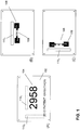
- FIG. 1A-1C schematically depict bib tag assemblies according to various embodiment of the invention.
- Fig. 1A and 1B depict the front and backside of a bib tag assembly for use e.g. in a sports event comprising a support sheet 102, e.g. a flexible, light-weight, water-resistant, sheet-like material that is adapted to be affixed to a person through the use of an adhesive or mechanism to pin or tie the support sheet to the person or animal (or clothing on the person or animal).
- exemplary materials used for support sheet include fabric, paper, woven sheet, plastic or any combination thereof.
- a front side of the support sheet may display an identifier such as an identifier 104 identifying the person to which the support sheet is affixed.
- Support sheet 102 may have a rectangular, 4-sided shape, but in other embodiment it may have any suitable shape, e.g., shape of a logo.
- Fig. 1B depicts the backside of the support sheet to which at least one tag 108 is affixed.
- the tag may comprise an antenna 106 for receiving and transmitting signals.
- the tag may relate to an UFH tag operating in the UHF frequency range.
- the tags or tag structures described below may be configured to operate in the frequency range between 800 and 1000 MHz.
- a tag may operate in a frequency range between 860 and 960 MHz.
- the tag may operate in a frequency range between 900 and 930 MHz.
- a tag may operate in a frequency range between 940 and 970 Mhz.
- the antenna associated with the tag may have a predetermined shape.
- the antenna may be a metallic (foldable and/or flexible) thin-film layer.
- the tag may have the form of a dipole antenna.
- the unfolded length of the tag may be approximately half the wavelength of the operation frequency, e.g. between 10-20 cm (900 MHz equals approximately 16 cm).
- the tag may further comprise a processor, i.e. an RFID-specific processor, for processing signals received by the tag.
- Tag 108 may be securely attached to support sheet 102 by means such as an adhesive or an adhesive layer. Depending on the application, the tag may be at least partly active and/or passive. In some embodiments, instead of the back-side, the tag may be affixed to the front-side of the bib.
- the bib tag assembly may further comprise an expandable spacer configured to create a spacing between the tag and the wet clothing and/or body of the participant.
- an expandable spacer refers to a spacer structure having an adjustable thickness or height or is able to have a particular range of thicknesses or heights.
- the expandable spacer may have a collapsed/compressed state with a small thickness or height, and an expanded state with a larger thickness or height.
- the spacer may have the form of one or more parts formed of expandable sheet material 110 1 located in the vicinity and/or (partly) on top of the tag/antenna structure 106,108.
- the expandable spacer may be configured such that when the bib tag assembly is not in use, (e.g. assembled for distribution to participants of an event), the spacer is in a collapsed (non-expanded) state. In that case, the spacer may be in the form of a thin flexible sheet or structure attached to the backside of the bib. In the non-expanded state, the spacer may have a thickness of approximately less than 3 millimetres, preferably less than 2 millimetres. This way, a bib tag assembly may be very thin so that easy distribution by post is possible.
- the material or structure when the expandable spacer is in its expanded state, may have a desired thickness so that is functions as a spacer for eliminating or at least decreasing detuning of the tag due to the close presence of the body of the wearer of the bib tag assembly. Desired thicknesses of the expandable spacer in expanded state may be between approximately 5 and 15 mm. For an UHF tag in use, the spacer may expand to a thickness of around 10 mm. In the expanded state, the spacer provides a desired distance between the tag and the wet shirt and/or body such that the negative influence of the wet shirt and/or body are considerably reduced.
- the tag/antenna structure may be attached to the bib such that its longitudinal axis is parallel to the ground surface.
- the tag signal may be picked up by a detection antenna, which is located on the ground (e.g. by use of an antenna mat) or above the athlete to be detected.
- the tag/antenna structure 106,108 and the associated expandable spacer structure 110 2 may be attached to the bib such that its longitudinal axis is perpendicular to the ground surface.
- the tag signal may be picked up by a detection antenna, which is located at at least one side of the athlete's path of travel.
- the expandable nature of the spacer may be achieved differently depending on the desired application.
- the expansion may be achieved by a material that expands in volume to a desired thickness.
- the spacer may be enabled by a mechanical structure that expands in size or enforces a certain distance/space between the bib and the body of the user wearing the bib when the structure is in its expanded state.
- the expandable spacer may expand in a self-acting manner which does not require no user interaction/configuration or in a manner that requires only little user action/configuration. Moreover, the expandable spacer is configured to expand to a desired height or thickness without the risk of improper expansion of the spacer due to human errors.
- the spacer preferably has collapsed state (i.e., reduced thickness) such that shipping large quantities of the bibs is practical. After shipping, the spacer may expand before the bib is attached to clothing/body, or during the use of the bib, e.g., during a race.
- a common material that is expandable is a porous material such as foam and sponge.
- Foam is capable of expanding in size when gas or moisture fills voids, holes or bubbles in the foam thereby enlarging the volume of the foam.
- An example of such foam is self-expanding foam used in insulation of homes or grow toys that expand in water.
- Sponge-like materials are capable of expanding in size when holes in the sponge absorbs moisture or take in air/gas.
- porous material Besides absorbing moisture to expand in size, some types of porous material expand and contract in size in response to pressure changes.
- a porous material that is packaged in a vacuum-sealed bag may be in a compressed form. If the vacuum-seal of the bag is broken, the porous material may expand by taking in air into the pores of the material.
- Various expandable spacer structures are described hereunder in more detail with reference to Fig. 3-8 .
- Fig. 2A-2C depict a timing system for use with a bib tag assembly 202 according various embodiments of the invention.
- Fig. 2C depicts a schematic of a top-view of a timing system, which may comprise a detection antenna 208 connected to a decoder 206.
- the detection antenna may be configured as an elongated antenna mat placed on the ground, in the path of travel of the athletes, wherein the antenna mat may comprise one or more antennas configured to pick up signals transmitted by the bib-tag assembly.
- the detection antenna may be located at the side or above the path of travel of the athletes.
- different antenna implementations e.g. a patch antenna, a slot antenna or a yagi antenna, may be used.
- the tag may be configured as a passive backscatter system wherein the tag transmits a modulated signal 204 to the detection antenna. If a participant wearing a bib tag assembly 202 1-5 comes in the vicinity of the detection antenna, the tag antenna may receive the modulated signal 201, which is used to power-up the processor in the tag.
- Fig. 2A depicts e.g. an implementation wherein a detection antenna mat 210 transmits a modulated signal 201 in a direction opposite to the direction in which the athlete wearing the bib tag is moving.
- Fig. 2B depicts a detection antenna 210 located at a side of the athlete's path of travel wherein the detection antenna transmits a modulated signal towards on side of the athlete wearing a bib tag.
- the tag transmits information stored in the processor back to the detection antenna on the basis of a modulating back-scattered signal 203 1 .
- the tag may start sending out messages 203 1-4 comprising at least a unique ID identifying the bib.
- the detection antenna may pick up the transmitted messages and transfer them to the decoder, which comprises a processor for executing an algorithm 212 for determining the (spit) time associated with the tag on the basis of time of detection and the signal strength of the received ID messages.
- the processed data may be subsequently stored in a storage 214, e.g. a database, for further use.
- the decoder algorithm may determine the exact passing of a tag above the centre-line of the antenna mat. Determination of the time that the tag passes the centre-line requires measuring the signal strength of multiple messages originating from a tag. It is therefore very important that optimal signal transfer between the tag and the antenna mat is achieved. This may be achieved by bib tag assembly comprising an expandable spacer, which allows expansion to a desired optimum thickness.
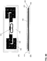
- Fig. 3A-3D depict an embodiment of an expandable tag spacer for use in a bib tag assembly according to an embodiment of the invention.
- Fig. 3A-3C depict at least part of a support sheet 302 to which a expandable sheet material 304 is attached to.
- the sheet material may comprise a thin sheet of water-expandable material.
- the water-expandable material may be a pressed sponge-like material, such as pressed celluloses, which absorbs water and/or moisture 306 by using capillary action to fill small holes in the interior of the sponge material.
- the material may be affixed to the backside of the bib and may have the form of strip in close vicinity and/or (partly) on top of the tag as illustrated.
- the sweat of the athlete will be partly absorbed by the water-absorbing material so that the material will start expanding as schematically indicated in Fig. 3A-3C .
- the expansion of the material is limited to one dimension (i.e. the z-dimension perpendicular to the x-y plane of the support sheet) in order to avoid the development of tension in the plane of the bib.
- the thickness of the water-expandable material in expanded state may be selected such that the spacer has a thickness of about 10 mm, i.e. a spacer thickness which allows good coupling between the tag backscatter signal and the detection antenna in the UHF frequency range.
- Fig. 3D depicts the effect of the expansion at various stages for a pressed cellulose material. This figure clearly shows that the thickness of the material in the expanded state may be easily 5-15 times the thickness of the material in the pressed state.
- water-expandable material is not limited to water-expandable material based on sponge-like materials such pressed celluloses, but may encompass any type of material, which provides considerable expansion in at least one dimension.
- the water-expandable material may be biodegradable.
- Fig. 4A depicts expandable tag spacers according to various embodiments of the invention.
- Fig. 4A (A) and (B) depict top view and a side view of an embodiment wherein, the spacer may comprise several pieces of expandable sheet material which may be provided onto (or fixed to) the tag structure.
- the tag structure may include a processor such as an integrated circuit (IC) for receiving, processing and transmitting RFID signals 404 and the metallic thin-film antenna structure 406, which is provided onto a flexible support sheet 402.
- the processor and the metallic thin-film antenna structure may be covered with a passivation layer (not shown), e.g. a thin-film insulating layer.
- the backside of the support sheet may comprise an adhesive such that the tag structure may be attached as a sticker to a bib.
- Pieces of the expandable sheet material 408 1-23 forming an expandable spacer structure may be attached to the front side of the tag structure.
- the expandable spacer structure may comprise e.g. two pieces of expandable material 408 1,2 provided the tag structure area comprising the antenna structures and at least one piece of expandable material 408 3 provided over the area comprising the tag processor.
- Fig. 4A (C) depicts a side view of the tag structure wherein the expandable spacer is in its expanded state.
- tag-structures may be provisioned with an expandable spacer structure during manufacturing of the tag structure.
- the tag structure may be provided with a expandable spacer structure in a post-processing step after manufacturing of the tag structure.
- Fig. 4A(D) depicts a further embodiment, wherein the tag structure comprises an expandable spacer structure 410 1,2 (e.g. two or more pieces of water-expandable sheet material similar to the ones described with reference to Fig. 4A (A)-(C) and a fixed spacer structure 412 of a predetermined thickness.
- the fixed spacer structure may have a thickness of about 2-6 mm and functions as a spacer structure for the time that the expandable structure has not expanded to its full height (e.g. at the beginning/start of the race when the athletes are not yet sufficiently sweating in order to active that expandable spacer structures.
- Fig. 4B depict top view and side view of a tag structure according to various other embodiments of the invention.
- the tag structure may comprises a processor 404 and a metallic thin-film antenna structure 406 provided onto a flexible support sheet 402.
- the processor and the metallic thin-film antenna structure may be protected by a (thin-film) passivation layer.
- An expandable spacer structure 414 is disposed onto at least part of the antenna and processor area of the tag structure.
- the expandable spacer structure may have a multilayered structure comprising at least an expandable sheet material 408 and one or more dielectric layers 416.
- Fig. 4B (B) depicts a side-view of an expandable spacer structure comprising an expandable sheet material 408 and at least one layer of a dielectric having a relatively high dielectric constant 416.
- the antenna structure of the tag may be impedance matched (i.e. tuned) to the tag processor taking into account the presence of the thin film dielectric layer of relatively high dielectric constant between 10 and 50 in the direct proximity of said antenna structure.
- a dielectric layer may partially "screen" the proximity of the body.
- the layer may have a thickness of between 0.05 and 5 mm.
- the layer may comprise titanium dioxide.
- the layer may be formed of a polymer comprising titanium dioxide particles as a filler in order to increase the dielectric constant of the layer to a desired value.
- the dielectric layer 416 may comprise multiple dielectric layers, for example a first dielectric layer of a relatively low dielectric constant (e.g. between 1 and 5) at the interface with the tag structure and a second dielectric layer of a relatively high dielectric constant (between 10-50) on top of the first thin-film dielectric layer at the interface with the expandable spacer layer 408.
- a first dielectric layer of a relatively low dielectric constant e.g. between 1 and 5
- a second dielectric layer of a relatively high dielectric constant between 10-50
- the dielectric layers may formed on the basis of a polymer comprising one or more dielectric fillers (e.g. titanium dioxide, silicon dioxide, aluminium dioxide, aluminosilicates, etc.) in order to form a dielectric layer of a desired dielectric constant.
- the dielectric constant of such layer may be controlled by controlling the composition and/or concentration of the dielectric fillers (mixture) in the polymer carrier layer.
- the expandable spacer for use in a bib tag provides a simple and very cost efficient way of providing a desirable distance between the body and the tag.
- the spacer is activated when the body starts to sweat.
- the water-expandable material may come in very thin flexible sheets, it does not affect the thickness of the bib tag assembly when it is stored or distributed to users. Moreover, no human intervention is needed to activate the spacer.
- Fig. 4A and 4B it is submitted that the disclosure is not limited to the examples of Fig. 4A and 4B but also encompasses many different layouts and (multi-layered structures).
- the layered expandable spacer structures described with reference to Fig. 4B may be implemented in a accordance with one of the possible layouts as described with reference to Fig. 4A .
- FIG. 5A-5C depict schematics of an expandable spacer structure according to another embodiment of the invention.
- Support sheet 514 is shown in FIG. 5A-5C with an expandable spacer having several parts.
- the spacer has cover 524 (or wrapping material) that is adapted to vacuum-seal and compress expandable material 522. While cover 524 maintains a vacuum-sealed state, expandable material 522 is in a compressed state having a reduced height/thickness. The compressed state facilitates shipping and storage of said assembly.
- Vacuum-seal cover 516 may be a tape-like material that adheres (e.g., removably attached) to cover 524 to keep hole 520 sealed (see FIG. 5B ).
- the thickness of the expandable material may be selected such that the spacer has a thickness in a range between 5 and 15 mm.
- Vacuum-seal cover 516 may be part of a top sheet 512. Alternatively, vacuum-seal cover 516 may be securely attached to top sheet 512. In embodiments where a top sheet is used, when top sheet 512 (and vacuum-seal cover 516 ) is pulled away from support sheet 514, hole 520 is exposed thus breaking the vacuum-seal. Top sheet 512 may be joined with support sheet 514 at an edge. Alternatively, top sheet 512 may be a portion of a folded support sheet 514.
- the backside of the expandable spacer structure may comprise an adhesive such that it may be fixed to the backside of a bib like a sticker.
- a bib tag assembly as e.g. described with reference to Fig. 1 may be provided with such expandable spacer structure. When affixing the bib tag assembly to a shirt, the user only needs to break the vacuum-seal in order to bring the spacer structure into its expanded state.
- Fig. 6A-6C depict schematics of an expandable spacer structure according to yet another embodiment of the invention.
- a cover providing pressure onto an expandable material resulting in a compressed state of the expandable material
- the expandable material expands to the desired thickness in order to function as a spacer for a bib tag assembly.
- Exemplary compression means is shown as cover 608 having at least two portions 604, 606 that enables cover 608 to firmly and tightly compress expandable material 610, e.g. a foam sheet, to supporting sheet 602.
- Cover 608 firmly applies pressure to expandable material 610 and may be removably attached to support sheet 602 at portion 604 and/or 606. When cover 608 is removed or opened, the compressed material expands in thickness/height to serve as a spacer, as seen in Fig. 6C .
- the backside of the expandable spacer structure may comprise an adhesive such that it may be fixed to the backside of a bib like a sticker.
- a bib tag assembly as e.g. described with reference to Fig. 1 may be provided with such expandable spacer structure. When affixing the bib tag assembly to a shirt, the user only needs to remove the cover in order to bring the spacer structure into its expanded state.
- Fig. 7A-7B depict schematics of an expandable spacer structure according to yet another embodiment of the invention.
- mechanical means for an expandable spacer may be used to create the desired space between the support sheet (as well as the tag) and the body.
- one side of carton 704 is used as a spacer, and said carton is firmly affixed to supporting sheet 702.
- Said carton is preferably made of a semi-rigid material that is capable of holding shape and structure in its expanded form.
- FIG. 7B compressed state
- Fig. 7D expanded state
- spacer comprises expandable portion 708 and fixed portion 706, where fixed portion 706 is firmly affixed to supporting sheet 702.
- Fig. 8A-8D depict schematics of an expandable spacer structure according to various other embodiments of the invention.
- mechanically foldable structures fixed to a support sheet 802 e.g. a bib, are used as expandable spacer.
- These spacer structures may have a folded state ( Fig. 8A and 8C ) and an expanded state ( Fig. 8B and 8D ).
- the spacer structure may comprise first and second support members 804 1,2 and first and second side members 806 1,2 , which are pivotably connected to the support members.
- the structure may be made of carton or another suitable material that has sufficient mechanical strength to serve as a reliable spacer in its expanded (erected) state.
- the spacer when folded the support and side members substantially parallel to the support sheet.
- the spacer may be erected by a user by a pulling force F parallel to the support sheet. Due to the force, the side members are erected in a position substantially perpendicular to the support member thereby creating a desired spacing S between first and second members.
- a simple fixation mechanism e.g. a latch 808, may be used to fixate the structure so to keep the structure in its expanded (erected) state.
- the folded mechanical spacer structure may be configured such that at least part of the pivotable connections between the support and side members is configured to provide a spring force 810, forcing the spacer structure to be in its erected state.
- a cover 812 may firmly applies pressure to the mechanically expandable spacer structure and may be removably attached to support sheet.
- the spring force will cause the structure to go to its erected state (similar to the situation as described with reference to Fig. 6 .
- an inflatable air pouches may also be used as a spacer.
- a pouch may be self-inflating or manually-inflatable by blowing air into the pouch.
- Fig. 9A-9C depict schematics of a bib tag assembly according to further embodiments of the invention.
- efficient coupling between the tag and the antenna is desired when the athlete approaches the antenna.
- only a small part of the signal may be picked up by the antenna.
- the tag assembly may comprise a bib 902 comprising a tag 904 and an expandable spacer structure 906 1 (this spacer structure may be implemented in accordance with one of the embodiment as described with reference to Fig.
- the desired signal focussing direction 912 is in the direction of the antenna mat 914, i.e. downwardly, right in front of the participant wearing the bib tag assembly.
- the tag may comprise a dipole antenna of an elongated shape.
- the length is approximately half the wavelength of the operation frequency.
- the antenna signal may be read by an antenna which is positioned in front, above or under the athlete.
- a conductive passive element 908, e.g. a conductive strip or wire of length L, which is longer than the (effective) length of the tag and which is positioned at a certain distance above the tag may function as a reflector. In that case, if a tag transmits a message (e.g.
- a backscattered modulated signal to the antenna mat, part of the signal that is transmitted in a direction away from the antenna mat is reflected back towards the mat antenna, thereby effectively providing means for directing a larger part of the transmitted signal in a particular direction. This way the signal strength of the transmitted message is enhanced and the chance that the message is detected becomes larger.
- the reflector may have a length L selected within a range between 100 and 300 mm, preferably 150 and 250 mm, wherein the length of the reflector is longer than the (effective) length of the tag.
- the width W of the reflector may be within a range between approximately 1 to 25 mm.
- the distance D between the reflector and the tag may be selected between 50 and 100 mm.
- the tag may be operated in the UHF range, preferably at a frequency of 865 MHz or 915 MHz.
- the reflector may have the form of a conductive thin-film sheet fixed to the bib.
- Conductive materials may include aluminium, copper, conductive polymers and/or inks known in the art.
- the reflector may be in the shape of a conductive wire, which is fixed to or integrated into the bib material.
- a conductive ink or a moist sponge material may be used to form a conductive reflector pattern onto the bib.
- a nett gain of approximately 6 dB may be achieved. This allows an increase of the reading distance between a tag and the antenna mat of approximately 30-35%.
- further improvement in the tag signal may be achieved using a battery-assisted tag. In that case, a very thin battery in the tag may provide power to feed the IC of the tag.
- the bib-tag assembly in Fig. 9B comprises further passive elements 910 1,2 which are positioned under the tag. These conductive passive elements may be positioned substantially parallel to the tag and have a length which is smaller than the tag length. These passive elements, which are referred to as directors, may help to focus the transmitted in a downward direction. Typically, one or multiple directors may be used. The further a director is position from the tag, the short the length of the director (see e.g. Fig. 9B wherein director 910 2 is shorter than director 910 1 ).
- the bib-tag assemblies in Fig. 9A and 9B may further comprise expandable spacer structures 906 2 , 906 3 onto and/or within the direct proximity of the reflector and/or director structures such that these passive structures are not or at least less negatively influenced by the direct proximity of the (wet) body of the wearer of the bib-tag assembly.
Description
- The invention relates to a sports bib for use in an RFID tag assembly.
- Radio Frequency Identification (RFID) tags are widely used for automatic time and/or location registration systems in sporting events. Typically an RFID tag comprises a microchip combined with an antenna and is structured to allow attachment to an object to be detected. In such time registration systems every participant is provided with an RFID tag, which is removable secured to a shoe or a bib comprising a number, which is associated with the name and/or address of the participant. If a participant crosses a detection antenna an electro-magnetical coupling between the tag and the antenna is established thereby allowing information exchange, e.g. an identify number associated with the tag, between the tag and a detector connected to the antenna.
- Currently there is a development towards the use of so-called ultra-high frequency (UHF) tags, which use frequency in the UHF band between approximately 860 and 960 MHz. These tags are much cheaper (so that they can be used as a one-time use disposable tag), are less in weight, and can be read faster and from larger distances when compared with low frequency tags. From a logistic and organisational point of view, tags are preferably distributed together with or attached to the bib so that there is an unambiguous one-to-one relation between the tag and the bib. The bib is fixed to the shirt such that the bib is located in front of the chest of the participant.
- When fixing an UHF tag to a bib certain problems occur. One problem relates to the fact that the tag is within close proximity of the body, which for the tag functions as a dielectric of relatively high dielectric constant. The proximity of the body changes the impedance of the tag antenna thereby "detuning" the tag away from its optimum working point. Due to this detuning effect, the tag may not able to generate detectable modulated backscatter signal. The effect of detuning is further enhanced in a wet environment, e.g. wet and sweaty clothing and/or body of an athlete. This way, the signal may further deteriorate thereby increasing the risk that a participant crossing or passing a detection antenna is not or at least not correctly registered by the timing system.
- In order to lift at least part of this problem, a spacer in the vicinity of the tag may be used such that at least a certain distance between the tag and the wet clothes and/or body is provided. Such spacer may have the form of a strip of lightweight foam attached to or in the vicinity of the tag. Ideally such spacer should guarantee a spacing distance of about 10 mm, however such thickness makes such tag bib assemblies not suitable for mass distribution (by post) and storage (e.g. millions or more). Therefore, in practice, spacers are used which are thinner than the desirable optimal thickness. Hence, conventional spacers thus allow only sub-optimal performance of the tag.
-
US 2008/0018428 discloses a communication device that includes a radio frequency identification tag that performs a radio communication with a predetermined device. This communication device can be attached to goods or products stored in a warehouse or the like. A space adjustment unit, which comprises a space adjustment screw and a spring, is configured to adjust a space between a metal plate and the radio frequency identification tag. This makes it possible to easily and effectively control the distance and the directivity of the radio communication. -
US 6,542,114 discloses a loader that can be used to load or unload a plane. The loader has a horizontal platform and has a powered scissors support for the platform which is capable of vertically raising and lowering the platform. The platform supports a pallet and the pallet in turn supports several items that each have a beacon tag on it. -
US 2007/0164866 discloses a security document having a contactless chip with data masking. The security document comprises a transponder connected to an antenna, serving to remotely communicate with a reader via an electromagnetic coupling, and a passive masking element of this antenna. This masking element is capable of rendering the reading of the document impossible when the security document is closed. - A further problem associated with the use of a tag bib assembly is that the tag signal may be influenced by nearby objects. Especially when a lot of participants are crossing an antenna simultaneously, the presence of other persons in the direct proximity of the radiated signal may cause that only a very small part of the signal will be picked up by the detection antenna of the timing system. Hence, when using a tag bib assembly, it is desired that the tag signal is directed towards the detection antenna.
-
US Patent 7,948,383 describes an RFID tag assembly for a shoe. In particular, the tag is removed from a bib and secured to a participant's shoe prior to a race. Attaching the RFID tag to the shoe requires multiple actions of the user. Improper installation of the tag to the shoe may result in a disfunctioning or even a non-functioning tag. - Accordingly, there is a need to provide an improved tag assembly, which at least alleviates at least part of these problems. In particular, there is a need for improved tag bib assemblies, in particular UHF tag bib assemblies, which are suitable for fixing to the shirt of a participant and which are not or much less affected by the wet clothes and/or body of the participant. Further, there is a need for improved tag bib assemblies, which allow the generation of a signal, which is focussed towards the detection antenna.
- It is an objective of the invention to reduce or eliminate at least one of the drawbacks known in the prior art. The invention relates to a device as claimed in
claim 1. - The advantageous expandable spacer may be in the form of a thin flexible sheet or structure having thin a non-expanded state (the spacer may have a thickness of approximately less than 3 millimetres, preferably less than 2 millimetres) providing a bib tag assembly which may be easily distributed and stored; and, an expanded state, wherein the material or structure may have a desired thickness so that is functions as a spacer for eliminating or at least decreasing detuning of the tag due to the close presence of the body of the wearer of the bib tag assembly. In the expanded state, the spacer provides a desired distance between the tag and the wet shirt and/or body such that the negative influence of the wet shirt and/or body are considerably reduced.
- In an embodiment said expandable spacer may comprise one or more pieces of absorbing material adapted to expand at least in one dimension in a damp and/or wet environment, preferably said absorbing material comprising pressed cellulose. In this embodiment, expansion of the spacer does not require any action of the user thereby reducing the risk of tag that does not function properly.
- In an embodiment said expandable spacer may comprise one or more pieces of resilient material adapted to adjust at least one dimension in response to a change in pressure and/or an applied force. In an embodiment said non-expandable state may include said resilient material being vacuum packaged or packaged under an applied force, preferably under pressure, said expansion to said expanded stated being initiated by breaking said vacuum or said pressurized package. In an embodiment said expandable spacer may comprise one or more pieces of chemically expandable material. In a further embodiment said expandable spacer may comprise at least one mechanically expandable structure. In yet a further embodiment said at least one mechanical expandable structure may be configured as a foldable structure having collapsed state and an erected state of a predetermined spacer thickness. In another embodiment said spacer may be configured as a self-erecting structure.
- In an embodiment spacer in said expanded state may have a thickness in a range between 5 and 15 mm, preferably between 8 and 12 mm. In an embodiment said spacer in said non-expanded state may have a thickness smaller than 5 mm, preferably smaller than 3 mm.
- In an embodiment said tag may comprise at least one metallic dipole antenna structure and wherein said spacer structure may be located within the proximity of said antenna structure and/or at least partly on top of said dipole antenna structure.
- In an embodiment said tag may be operative in the ultra-high frequency range, preferably in the range between 800 and 1000 MHz
- In an embodiment said support sheet may be a bib comprising a printed identifier, preferably said transmitted signal comprising an identifier associated with said printed identifier.
- In a variant said support sheet may further comprise one or more metallic passive elements for directing at least part of said signal into a predetermined direction. In another variant at least one of said passive elements may be configured as a reflector, preferably the length of said reflector being larger than the length of said tag. In yet another variant at least one of said passive elements may be configured as a director, preferably the length of said director being smaller than the length of said tag. In a further variant at least one of said passive elements may be formed onto said support sheet using conductive ink or coating. The use of passive elements in combination with one or more expandable spacer structures provides a tag assembly which is capable of producing a signal which is not or at least less influenced by the direct proximity of the body and which is effectively focussed into a desired direction.
- In yet a further variant said assembly may further comprise a non-expandable spacer structure disposed on said support sheet, said expandable spacer structure providing a predetermined spacing between said tag and said body when said expandable spacer structure is not in its expanded state.
- In an variant said non-expandable spacer structure has a thickness between 2 mm and 6 mm.
- In an variant said assembly may further comprise at least a dielectric layer disposed between said tag structure and said expandable spacer structure, wherein said dielectric layer comprises a high-dielectric material and wherein said metallic thin-film antenna structure is impedance matched to said processor taking into account the presence of said dielectric layer in the direct proximity of said antenna structure. The presence of a dielectric layer may partially "screen" the proximity of the body away from the tag so that detuning effects associated with the proximity of the body can be considerably reduced.
- The invention will be further illustrated with reference to the attached drawings, which schematically will show embodiments according to the invention. It will be understood that the invention is not in any way restricted to these specific embodiments.
-
-
Fig. 1A-1C schematically depict bib tag assemblies according to various embodiment of the invention; -
Fig. 2A-2C depict a timing system for use with a bib tag assembly according various embodiments of the invention; -
Fig. 3A-3D depict an embodiment of an expandable tag spacer for use in a bib tag assembly according to an embodiment of the invention; -
Fig. 4A-4B depicts expandable tag spacers according to various embodiments of the invention; -
Fig. 5A-5C depict schematics of an expandable spacer structure according to another embodiment of the invention; -
Fig. 6A-6C depict schematics of an expandable spacer structure according to yet another embodiment of the invention; -
Fig. 7A-7B depict schematics of an expandable spacer structure according to yet another embodiment of the invention; -
Fig. 8A-8D depict schematics of an expandable spacer structure according to various other embodiments of the invention; -
Fig. 9A-9C depict schematics of a bib tag assembly according to a further embodiment of the invention. -
Fig. 1A-1C schematically depict bib tag assemblies according to various embodiment of the invention. In particular,Fig. 1A and 1B depict the front and backside of a bib tag assembly for use e.g. in a sports event comprising asupport sheet 102, e.g. a flexible, light-weight, water-resistant, sheet-like material that is adapted to be affixed to a person through the use of an adhesive or mechanism to pin or tie the support sheet to the person or animal (or clothing on the person or animal). Exemplary materials used for support sheet include fabric, paper, woven sheet, plastic or any combination thereof. Preferably, a front side of the support sheet may display an identifier such as anidentifier 104 identifying the person to which the support sheet is affixed.Support sheet 102 may have a rectangular, 4-sided shape, but in other embodiment it may have any suitable shape, e.g., shape of a logo. -
Fig. 1B depicts the backside of the support sheet to which at least onetag 108 is affixed. In order to make the tag suitable for a sports timing system, the tag may comprise anantenna 106 for receiving and transmitting signals. In one embodiment, the tag may relate to an UFH tag operating in the UHF frequency range. In more general, the tags or tag structures described below may be configured to operate in the frequency range between 800 and 1000 MHz. In one embodiment, a tag may operate in a frequency range between 860 and 960 MHz. in another embodiment, the tag may operate in a frequency range between 900 and 930 MHz. In yet another embodiment, a tag may operate in a frequency range between 940 and 970 Mhz. The antenna associated with the tag may have a predetermined shape. The antenna may be a metallic (foldable and/or flexible) thin-film layer. - In one embodiment, the tag may have the form of a dipole antenna. The unfolded length of the tag may be approximately half the wavelength of the operation frequency, e.g. between 10-20 cm (900 MHz equals approximately 16 cm). The tag may further comprise a processor, i.e. an RFID-specific processor, for processing signals received by the tag.
Tag 108 may be securely attached to supportsheet 102 by means such as an adhesive or an adhesive layer. Depending on the application, the tag may be at least partly active and/or passive. In some embodiments, instead of the back-side, the tag may be affixed to the front-side of the bib. - The bib tag assembly may further comprise an expandable spacer configured to create a spacing between the tag and the wet clothing and/or body of the participant. Here, an expandable spacer refers to a spacer structure having an adjustable thickness or height or is able to have a particular range of thicknesses or heights. In one embodiment, the expandable spacer may have a collapsed/compressed state with a small thickness or height, and an expanded state with a larger thickness or height.
- The spacer may have the form of one or more parts formed of expandable sheet material 1101 located in the vicinity and/or (partly) on top of the tag/antenna structure 106,108. The expandable spacer may be configured such that when the bib tag assembly is not in use, (e.g. assembled for distribution to participants of an event), the spacer is in a collapsed (non-expanded) state. In that case, the spacer may be in the form of a thin flexible sheet or structure attached to the backside of the bib. In the non-expanded state, the spacer may have a thickness of approximately less than 3 millimetres, preferably less than 2 millimetres. This way, a bib tag assembly may be very thin so that easy distribution by post is possible.
- In contrast, when the expandable spacer is in its expanded state, the material or structure may have a desired thickness so that is functions as a spacer for eliminating or at least decreasing detuning of the tag due to the close presence of the body of the wearer of the bib tag assembly. Desired thicknesses of the expandable spacer in expanded state may be between approximately 5 and 15 mm. For an UHF tag in use, the spacer may expand to a thickness of around 10 mm. In the expanded state, the spacer provides a desired distance between the tag and the wet shirt and/or body such that the negative influence of the wet shirt and/or body are considerably reduced.
- In
Fig. 1B the tag/antenna structure may be attached to the bib such that its longitudinal axis is parallel to the ground surface. In this configuration, the tag signal may be picked up by a detection antenna, which is located on the ground (e.g. by use of an antenna mat) or above the athlete to be detected. Alternatively, as depicted inFig. 1C , the tag/antenna structure 106,108 and the associated expandable spacer structure 1102 may be attached to the bib such that its longitudinal axis is perpendicular to the ground surface. In that configuration, the tag signal may be picked up by a detection antenna, which is located at at least one side of the athlete's path of travel. - The expandable nature of the spacer may be achieved differently depending on the desired application. For example, the expansion may be achieved by a material that expands in volume to a desired thickness. In another example, the spacer may be enabled by a mechanical structure that expands in size or enforces a certain distance/space between the bib and the body of the user wearing the bib when the structure is in its expanded state.
- The expandable spacer may expand in a self-acting manner which does not require no user
interaction/configuration or in a manner that requires only little user action/configuration. Moreover, the expandable spacer is configured to expand to a desired height or thickness without the risk of improper expansion of the spacer due to human errors. During shipping, the spacer preferably has collapsed state (i.e., reduced thickness) such that shipping large quantities of the bibs is practical. After shipping, the spacer may expand before the bib is attached to clothing/body, or during the use of the bib, e.g., during a race. - A common material that is expandable is a porous material such as foam and sponge. Foam is capable of expanding in size when gas or moisture fills voids, holes or bubbles in the foam thereby enlarging the volume of the foam. An example of such foam is self-expanding foam used in insulation of homes or grow toys that expand in water. Sponge-like materials are capable of expanding in size when holes in the sponge absorbs moisture or take in air/gas.
- Besides absorbing moisture to expand in size, some types of porous material expand and contract in size in response to pressure changes. A porous material that is packaged in a vacuum-sealed bag may be in a compressed form. If the vacuum-seal of the bag is broken, the porous material may expand by taking in air into the pores of the material. Various expandable spacer structures are described hereunder in more detail with reference to
Fig. 3-8 . -
Fig. 2A-2C depict a timing system for use with abib tag assembly 202 according various embodiments of the invention. In particular,Fig. 2C depicts a schematic of a top-view of a timing system, which may comprise adetection antenna 208 connected to adecoder 206. In one embodiment, the detection antenna may be configured as an elongated antenna mat placed on the ground, in the path of travel of the athletes, wherein the antenna mat may comprise one or more antennas configured to pick up signals transmitted by the bib-tag assembly. - In another embodiment (not shown in
Fig. 2C ), the detection antenna may be located at the side or above the path of travel of the athletes. Depending on the application different antenna implementations e.g. a patch antenna, a slot antenna or a yagi antenna, may be used. - In one embodiment, the tag may be configured as a passive backscatter system wherein the tag transmits a modulated
signal 204 to the detection antenna. If a participant wearing abib tag assembly 2021-5 comes in the vicinity of the detection antenna, the tag antenna may receive the modulatedsignal 201, which is used to power-up the processor in the tag. -
Fig. 2A depicts e.g. an implementation wherein adetection antenna mat 210 transmits a modulatedsignal 201 in a direction opposite to the direction in which the athlete wearing the bib tag is moving.Fig. 2B depicts adetection antenna 210 located at a side of the athlete's path of travel wherein the detection antenna transmits a modulated signal towards on side of the athlete wearing a bib tag. - In response, the tag transmits information stored in the processor back to the detection antenna on the basis of a modulating back-scattered signal 2031. This way, the tag may start sending out messages 2031-4 comprising at least a unique ID identifying the bib. The detection antenna may pick up the transmitted messages and transfer them to the decoder, which comprises a processor for executing an
algorithm 212 for determining the (spit) time associated with the tag on the basis of time of detection and the signal strength of the received ID messages. The processed data may be subsequently stored in astorage 214, e.g. a database, for further use. - As the electro-magnetical field produced by the antennas in the antenna mat is strongest above the (longitudinal) centre-
line 210 of the antenna, the decoder algorithm may determine the exact passing of a tag above the centre-line of the antenna mat. Determination of the time that the tag passes the centre-line requires measuring the signal strength of multiple messages originating from a tag. It is therefore very important that optimal signal transfer between the tag and the antenna mat is achieved. This may be achieved by bib tag assembly comprising an expandable spacer, which allows expansion to a desired optimum thickness. -
Fig. 3A-3D depict an embodiment of an expandable tag spacer for use in a bib tag assembly according to an embodiment of the invention.Fig. 3A-3C depict at least part of asupport sheet 302 to which aexpandable sheet material 304 is attached to. In this particular embodiment, the sheet material may comprise a thin sheet of water-expandable material. In one embodiment, the water-expandable material may be a pressed sponge-like material, such as pressed celluloses, which absorbs water and/ormoisture 306 by using capillary action to fill small holes in the interior of the sponge material. The material may be affixed to the backside of the bib and may have the form of strip in close vicinity and/or (partly) on top of the tag as illustrated. - During use, the sweat of the athlete will be partly absorbed by the water-absorbing material so that the material will start expanding as schematically indicated in
Fig. 3A-3C . Preferably, the expansion of the material is limited to one dimension (i.e. the z-dimension perpendicular to the x-y plane of the support sheet) in order to avoid the development of tension in the plane of the bib. The thickness of the water-expandable material in expanded state may be selected such that the spacer has a thickness of about 10 mm, i.e. a spacer thickness which allows good coupling between the tag backscatter signal and the detection antenna in the UHF frequency range.Fig. 3D depicts the effect of the expansion at various stages for a pressed cellulose material. This figure clearly shows that the thickness of the material in the expanded state may be easily 5-15 times the thickness of the material in the pressed state. - It is understood that the water-expandable material is not limited to water-expandable material based on sponge-like materials such pressed celluloses, but may encompass any type of material, which provides considerable expansion in at least one dimension. In one embodiment, the water-expandable material may be biodegradable.
-
Fig. 4A depicts expandable tag spacers according to various embodiments of the invention. In particular,Fig. 4A (A) and (B) depict top view and a side view of an embodiment wherein, the spacer may comprise several pieces of expandable sheet material which may be provided onto (or fixed to) the tag structure. In this particular embodiment, the tag structure may include a processor such as an integrated circuit (IC) for receiving, processing and transmittingRFID signals 404 and the metallic thin-film antenna structure 406, which is provided onto aflexible support sheet 402. The processor and the metallic thin-film antenna structure may be covered with a passivation layer (not shown), e.g. a thin-film insulating layer. The backside of the support sheet may comprise an adhesive such that the tag structure may be attached as a sticker to a bib. Pieces of theexpandable sheet material 4081-23 forming an expandable spacer structure may be attached to the front side of the tag structure. - The expandable spacer structure may comprise e.g. two pieces of
expandable material 4081,2 provided the tag structure area comprising the antenna structures and at least one piece ofexpandable material 4083 provided over the area comprising the tag processor. -
Fig. 4A (C) depicts a side view of the tag structure wherein the expandable spacer is in its expanded state. - The layout of the spacer structure may be designed such that with a minimum amount of expandable material a reliable spacing distance between the body and the tag structure is achieved. Hence, in this embodiment, tag-structures may be provisioned with an expandable spacer structure during manufacturing of the tag structure. Alternatively, the tag structure may be provided with a expandable spacer structure in a post-processing step after manufacturing of the tag structure.
-
Fig. 4A(D) depicts a further embodiment, wherein the tag structure comprises an expandable spacer structure 4101,2 (e.g. two or more pieces of water-expandable sheet material similar to the ones described with reference toFig. 4A (A)-(C) and a fixedspacer structure 412 of a predetermined thickness. The fixed spacer structure may have a thickness of about 2-6 mm and functions as a spacer structure for the time that the expandable structure has not expanded to its full height (e.g. at the beginning/start of the race when the athletes are not yet sufficiently sweating in order to active that expandable spacer structures. -
Fig. 4B (A) and (B) depict top view and side view of a tag structure according to various other embodiments of the invention. The tag structure may comprises aprocessor 404 and a metallic thin-film antenna structure 406 provided onto aflexible support sheet 402. The processor and the metallic thin-film antenna structure may be protected by a (thin-film) passivation layer. Anexpandable spacer structure 414 is disposed onto at least part of the antenna and processor area of the tag structure. - In these embodiments, the expandable spacer structure may have a multilayered structure comprising at least an
expandable sheet material 408 and one or moredielectric layers 416.Fig. 4B (B) depicts a side-view of an expandable spacer structure comprising anexpandable sheet material 408 and at least one layer of a dielectric having a relatively highdielectric constant 416. In this particular example, the antenna structure of the tag may be impedance matched (i.e. tuned) to the tag processor taking into account the presence of the thin film dielectric layer of relatively high dielectric constant between 10 and 50 in the direct proximity of said antenna structure. - The presence of a dielectric layer may partially "screen" the proximity of the body. In one embodiment, the layer may have a thickness of between 0.05 and 5 mm. In another embodiment the layer may comprise titanium dioxide. The layer may be formed of a polymer comprising titanium dioxide particles as a filler in order to increase the dielectric constant of the layer to a desired value.
- In further embodiments (not shown), the
dielectric layer 416 may comprise multiple dielectric layers, for example a first dielectric layer of a relatively low dielectric constant (e.g. between 1 and 5) at the interface with the tag structure and a second dielectric layer of a relatively high dielectric constant (between 10-50) on top of the first thin-film dielectric layer at the interface with theexpandable spacer layer 408. - In one embodiment, the dielectric layers may formed on the basis of a polymer comprising one or more dielectric fillers (e.g. titanium dioxide, silicon dioxide, aluminium dioxide, aluminosilicates, etc.) in order to form a dielectric layer of a desired dielectric constant. The dielectric constant of such layer may be controlled by controlling the composition and/or concentration of the dielectric fillers (mixture) in the polymer carrier layer.
- Hence, from the above it follows that the expandable spacer for use in a bib tag provides a simple and very cost efficient way of providing a desirable distance between the body and the tag. In one embodiment, the spacer is activated when the body starts to sweat. As the water-expandable material may come in very thin flexible sheets, it does not affect the thickness of the bib tag assembly when it is stored or distributed to users. Moreover, no human intervention is needed to activate the spacer.
- It is submitted that the disclosure is not limited to the examples of
Fig. 4A and4B but also encompasses many different layouts and (multi-layered structures). For example, the layered expandable spacer structures described with reference toFig. 4B may be implemented in a accordance with one of the possible layouts as described with reference toFig. 4A . -
Fig. 5A-5C depict schematics of an expandable spacer structure according to another embodiment of the invention.Support sheet 514 is shown inFIG. 5A-5C with an expandable spacer having several parts. The spacer has cover 524 (or wrapping material) that is adapted to vacuum-seal and compressexpandable material 522. Whilecover 524 maintains a vacuum-sealed state,expandable material 522 is in a compressed state having a reduced height/thickness. The compressed state facilitates shipping and storage of said assembly. Vacuum-seal cover 516 may be a tape-like material that adheres (e.g., removably attached) to cover 524 to keephole 520 sealed (seeFIG. 5B ). When the vacuum-seal cover is removed fromcover 524,hole 520 is exposed thus breaking the vacuum seal (seeFIG. 5C ) so that the material expands to its expanded state. The thickness of the expandable material may be selected such that the spacer has a thickness in a range between 5 and 15 mm. - Vacuum-
seal cover 516 may be part of atop sheet 512. Alternatively, vacuum-seal cover 516 may be securely attached totop sheet 512. In embodiments where a top sheet is used, when top sheet 512 (and vacuum-seal cover 516) is pulled away fromsupport sheet 514,hole 520 is exposed thus breaking the vacuum-seal.Top sheet 512 may be joined withsupport sheet 514 at an edge. Alternatively,top sheet 512 may be a portion of a foldedsupport sheet 514. - The backside of the expandable spacer structure may comprise an adhesive such that it may be fixed to the backside of a bib like a sticker. A bib tag assembly as e.g. described with reference to
Fig. 1 may be provided with such expandable spacer structure. When affixing the bib tag assembly to a shirt, the user only needs to break the vacuum-seal in order to bring the spacer structure into its expanded state. -
Fig. 6A-6C depict schematics of an expandable spacer structure according to yet another embodiment of the invention. In this particular embodiment, a cover providing pressure onto an expandable material (resulting in a compressed state of the expandable material) is removed or opened such that pressure would no longer be applied to the expandable material. When the pressure is no longer applied, the expandable material expands to the desired thickness in order to function as a spacer for a bib tag assembly. Exemplary compression means is shown ascover 608 having at least twoportions cover 608 to firmly and tightly compressexpandable material 610, e.g. a foam sheet, to supportingsheet 602. Cover 608 firmly applies pressure toexpandable material 610 and may be removably attached to supportsheet 602 atportion 604 and/or 606.
Whencover 608 is removed or opened, the compressed material expands in thickness/height to serve as a spacer, as seen inFig. 6C . - The backside of the expandable spacer structure may comprise an adhesive such that it may be fixed to the backside of a bib like a sticker. A bib tag assembly as e.g. described with reference to
Fig. 1 may be provided with such expandable spacer structure. When affixing the bib tag assembly to a shirt, the user only needs to remove the cover in order to bring the spacer structure into its expanded state. -
Fig. 7A-7B depict schematics of an expandable spacer structure according to yet another embodiment of the invention. In this particular embodiment, mechanical means for an expandable spacer may be used to create the desired space between the support sheet (as well as the tag) and the body. InFig. 7A and 7C , one side ofcarton 704 is used as a spacer, and said carton is firmly affixed to supportingsheet 702. When end portions are lifted and folded to create a tube-like shape,carton 704 is transformed from a flat carton to a spacer that has expanded in space. Said carton is preferably made of a semi-rigid material that is capable of holding shape and structure in its expanded form. An alternative embodiment is shown inFig. 7B (compressed state) andFig. 7D (expanded state), where spacer comprisesexpandable portion 708 and fixedportion 706, where fixedportion 706 is firmly affixed to supportingsheet 702. -
Fig. 8A-8D depict schematics of an expandable spacer structure according to various other embodiments of the invention. In this embodiment mechanically foldable structures fixed to asupport sheet 802, e.g. a bib, are used as expandable spacer. These spacer structures may have a folded state (Fig. 8A and 8C ) and an expanded state (Fig. 8B and 8D ). The spacer structure may comprise first andsecond support members 8041,2 and first and second side members 8061,2, which are pivotably connected to the support members. The structure may be made of carton or another suitable material that has sufficient mechanical strength to serve as a reliable spacer in its expanded (erected) state. - In these particular embodiments, when folded the support and side members substantially parallel to the support sheet. In the embodiment depicted by
Fig. 8A and 8B , the spacer may be erected by a user by a pulling force F parallel to the support sheet. Due to the force, the side members are erected in a position substantially perpendicular to the support member thereby creating a desired spacing S between first and second members. A simple fixation mechanism, e.g. alatch 808, may be used to fixate the structure so to keep the structure in its expanded (erected) state. - In a further embodiment, the folded mechanical spacer structure may be configured such that at least part of the pivotable connections between the support and side members is configured to provide a
spring force 810, forcing the spacer structure to be in its erected state. Hence, in that case, in order to keep the spacer in its folded state, acover 812 may firmly applies pressure to the mechanically expandable spacer structure and may be removably attached to support sheet. When the cover is removed or opened, the spring force will cause the structure to go to its erected state (similar to the situation as described with reference toFig. 6 . - One skilled in the art would appreciate other expandable spacer structure are also envisaged. For example, in one embodiment an inflatable air pouches may also be used as a spacer. A pouch may be self-inflating or manually-inflatable by blowing air into the pouch.
-
Fig. 9A-9C depict schematics of a bib tag assembly according to further embodiments of the invention. As already explained with reference toFig. 2 , efficient coupling between the tag and the antenna is desired when the athlete approaches the antenna. Typically, only a small part of the signal may be picked up by the antenna. Moreover, when a lot of athletes cross the antenna close together, the presence of other athletes close to a transmitting tag may further degrade the signal. For that reason, in the embodiments ofFig. 9A and 9B the tag assembly may comprise abib 902 comprising atag 904 and an expandable spacer structure 9061 (this spacer structure may be implemented in accordance with one of the embodiment as described with reference toFig. 1-8 ) and one or morepassive elements Fig. 3C , in certain applications the desiredsignal focussing direction 912 is in the direction of theantenna mat 914, i.e. downwardly, right in front of the participant wearing the bib tag assembly. - The tag may comprise a dipole antenna of an elongated shape. The length is approximately half the wavelength of the operation frequency. By fixing the tag in a horizontal position onto the bib, the antenna signal may be read by an antenna which is positioned in front, above or under the athlete. A conductive
passive element 908, e.g. a conductive strip or wire of length L, which is longer than the (effective) length of the tag and which is positioned at a certain distance above the tag may function as a reflector. In that case, if a tag transmits a message (e.g. a backscattered modulated signal) to the antenna mat, part of the signal that is transmitted in a direction away from the antenna mat is reflected back towards the mat antenna, thereby effectively providing means for directing a larger part of the transmitted signal in a particular direction. This way the signal strength of the transmitted message is enhanced and the chance that the message is detected becomes larger. - In one embodiment the reflector may have a length L selected within a range between 100 and 300 mm, preferably 150 and 250 mm, wherein the length of the reflector is longer than the (effective) length of the tag. In another embodiment, the width W of the reflector may be within a range between approximately 1 to 25 mm. In yet another embodiment, the distance D between the reflector and the tag may be selected between 50 and 100 mm. Here the tag may be operated in the UHF range, preferably at a frequency of 865 MHz or 915 MHz.
- The reflector may have the form of a conductive thin-film sheet fixed to the bib. Conductive materials may include aluminium, copper, conductive polymers and/or inks known in the art. In a further embodiment, the reflector may be in the shape of a conductive wire, which is fixed to or integrated into the bib material. In one embodiment, a conductive ink or a moist sponge material may be used to form a conductive reflector pattern onto the bib.
- Using a reflector as described above, a nett gain of approximately 6 dB may be achieved. This allows an increase of the reading distance between a tag and the antenna mat of approximately 30-35%. In one embodiment, further improvement in the tag signal may be achieved using a battery-assisted tag. In that case, a very thin battery in the tag may provide power to feed the IC of the tag.
- The bib-tag assembly in
Fig. 9B comprises furtherpassive elements 9101,2 which are positioned under the tag. These conductive passive elements may be positioned substantially parallel to the tag and have a length which is smaller than the tag length. These passive elements, which are referred to as directors, may help to focus the transmitted in a downward direction. Typically, one or multiple directors may be used. The further a director is position from the tag, the short the length of the director (see e.g.Fig. 9B whereindirector 9102 is shorter than director 9101 ). - The bib-tag assemblies in
Fig. 9A and 9B may further comprise expandable spacer structures 9062, 9063 onto and/or within the direct proximity of the reflector and/or director structures such that these passive structures are not or at least less negatively influenced by the direct proximity of the (wet) body of the wearer of the bib-tag assembly. - It is to be understood that any feature described in relation to any one embodiment may be used alone, or in combination with other features described, and may also be used in combination with one or more features of any other of the embodiments, or any combination of any other of the embodiments. Furthermore, equivalents and modifications not described above may also be employed without departing from the scope of the invention, which is defined in the accompanying claims.
Claims (11)
- A sports bib (902) comprising:a support sheet (102,302,402,514,602,702,802) for supporting a tag (108,904), said support sheet (102,302,402,514,602,702,802) comprising a printed identifier (104) on a first side; and,an expandable spacer (110,304,408,410,414, 522,610,804,806,906) disposed on a second side of said support sheet (102,302,402,514,602,702,802), said second side being opposite said first side, said expandable spacer (110,304,408,410,414,522,610,804,806,906) being configured to expand from a non-expanded state to an expanded state of a predetermined spacer thickness,characterized in that said expandable spacer (110,304,408,410,414,522,610,804,806,906) provides a predetermined spacing between said tag (108,904) and a body of a person, wherein said expandable spacer (110,304,408,410,414, 522,610,804,806,906) comprises one or more pieces of absorbing material adapted to expand at least in one dimension in a damp and/or wet environment.
- The sports bib (902) according to claim 1, wherein said absorbing material comprises pressed cellulose.
- The sports bib (902) according to claim 1 or 2, wherein said expandable spacer (110,304,408,410,414, 522,610,804,806,906) in said expanded state has a thickness in a range between 5 and 15 mm; and/or, wherein said expandable spacer (110,304,408,410,414, 522,610,804,806,906) in said non-expanded state has a thickness smaller than 5 mm.
- The sports bib (902) according to claim 3, wherein said expendable spacer in said expanded state has a thickness in a range between 8 and 12 mm; and/or, wherein said expendable spacer in said non-expanded state has a thickness smaller than 3 mm.
- The sports bib (902) according to any of claims 1-4 wherein said sports bib comprises said tag and said tag (108,904) comprises at least one metallic dipole antenna structure (106) and wherein said expendable spacer (110,304,408,410,414, 522,610,804,806,906) is located within the proximity of said antenna structure (106) and/or at least partly on top of said dipole antenna structure (106).
- The sports bib (902) according to any of claims 1-5 wherein said support sheet (102,302,402,514,602,702,802) further comprises one or more metallic passive elements (908,910) for directing at least part of said signal into a predetermined direction.
- The sports bib (902) according to claim 6, wherein at least one of said passive elements (908,910) is configured as a reflector (908).
- The sports bib (902) according to any of claims 1-7 wherein said sports bib (902) further comprises a non-expandable spacer structure (412,706) disposed on said support sheet(402,702), said non-expandable spacer structure providing a predetermined spacing between said tag and said body of said person when said expandable spacer structure (410,708) is not in its expanded state.
- The sports bib (902) according to claim 8, wherein said non-expandable spacer structure (412,706) has a thickness between 2 mm and 6 mm.
- The sports bib (902) according to any of claims 1-9, wherein said sports bib comprises said tag, said tag (108,904) comprises a processor (404) connected to a metallic thin-film antenna structure (406) and said expandable spacer (410) is disposed at least partly over said tag (108,904).
- The sports bib (902) according to claim 10 further comprising at least a dielectric layer (416) disposed between said tag (108,904) and said expandable spacer (410), wherein said dielectric layer (416) comprises a high-dielectric material and wherein said metallic thin-film antenna structure (406) is impedance matched to said processor (404) taking into account the presence of said dielectric layer (416) in the direct proximity of said antenna structure (406) .
Priority Applications (10)
| Application Number | Priority Date | Filing Date | Title |
|---|---|---|---|
| EP16170864.9A EP3086263B1 (en) | 2011-11-10 | 2011-11-10 | Rfid tag assembly |
| ES16170864T ES2727966T3 (en) | 2011-11-10 | 2011-11-10 | RFID tag set |
| SI201131734T SI3086263T1 (en) | 2011-11-10 | 2011-11-10 | Rfid tag assembly |
| PT16170864T PT3086263T (en) | 2011-11-10 | 2011-11-10 | Rfid tag assembly |
| HUE16170864A HUE043484T2 (en) | 2011-11-10 | 2011-11-10 | Rfid tag assembly |
| PL16170864T PL3086263T3 (en) | 2011-11-10 | 2011-11-10 | Rfid tag assembly |
| LTEP16170864.9T LT3086263T (en) | 2011-11-10 | 2011-11-10 | Rfid tag assembly |
| DK16170864.9T DK3086263T3 (en) | 2011-11-10 | 2011-11-10 | RFID tag assembly |
| HRP20190614TT HRP20190614T1 (en) | 2011-11-10 | 2019-03-29 | Rfid tag assembly |
| CY20191100494T CY1121676T1 (en) | 2011-11-10 | 2019-05-08 | RFID TAG ASSEMBLY |
Applications Claiming Priority (3)
| Application Number | Priority Date | Filing Date | Title |
|---|---|---|---|
| EP16170864.9A EP3086263B1 (en) | 2011-11-10 | 2011-11-10 | Rfid tag assembly |
| EP11782607.3A EP2776983B1 (en) | 2011-11-10 | 2011-11-10 | Rfid tag assembly |
| PCT/EP2011/069874 WO2013068043A1 (en) | 2011-11-10 | 2011-11-10 | Tag assembly |
Related Parent Applications (2)
| Application Number | Title | Priority Date | Filing Date |
|---|---|---|---|
| EP11782607.3A Division-Into EP2776983B1 (en) | 2011-11-10 | 2011-11-10 | Rfid tag assembly |
| EP11782607.3A Division EP2776983B1 (en) | 2011-11-10 | 2011-11-10 | Rfid tag assembly |
Publications (2)
| Publication Number | Publication Date |
|---|---|
| EP3086263A1 EP3086263A1 (en) | 2016-10-26 |
| EP3086263B1 true EP3086263B1 (en) | 2019-03-13 |
Family
ID=44983529
Family Applications (2)
| Application Number | Title | Priority Date | Filing Date |
|---|---|---|---|
| EP11782607.3A Active EP2776983B1 (en) | 2011-11-10 | 2011-11-10 | Rfid tag assembly |
| EP16170864.9A Active EP3086263B1 (en) | 2011-11-10 | 2011-11-10 | Rfid tag assembly |
Family Applications Before (1)
| Application Number | Title | Priority Date | Filing Date |
|---|---|---|---|
| EP11782607.3A Active EP2776983B1 (en) | 2011-11-10 | 2011-11-10 | Rfid tag assembly |
Country Status (19)
| Country | Link |
|---|---|
| US (2) | US10163054B2 (en) |
| EP (2) | EP2776983B1 (en) |
| JP (1) | JP5972388B2 (en) |
| CN (1) | CN104221038B (en) |
| AU (1) | AU2011380599B2 (en) |
| CY (1) | CY1121676T1 (en) |
| DK (1) | DK3086263T3 (en) |
| ES (2) | ES2591155T3 (en) |
| HR (1) | HRP20190614T1 (en) |
| HU (1) | HUE043484T2 (en) |
| IN (1) | IN2014CN03624A (en) |
| LT (1) | LT3086263T (en) |
| NZ (1) | NZ624796A (en) |
| PL (1) | PL3086263T3 (en) |
| PT (1) | PT3086263T (en) |
| RS (1) | RS58779B1 (en) |
| SI (1) | SI3086263T1 (en) |
| TW (1) | TW201342249A (en) |
| WO (1) | WO2013068043A1 (en) |
Families Citing this family (18)
| Publication number | Priority date | Publication date | Assignee | Title |
|---|---|---|---|---|
| SI3086263T1 (en) | 2011-11-10 | 2019-07-31 | Mylaps B.V. | Rfid tag assembly |
| GB2516005A (en) * | 2013-05-24 | 2015-01-14 | Trm Trading Uk Ltd | Associating devices to participants |
| ES2909959T3 (en) * | 2013-10-13 | 2022-05-11 | Mylaps B V | An assemblage of wearable sports timing labels |
| US10062958B2 (en) | 2014-11-21 | 2018-08-28 | Qualcomm Incorporated | Wearable electronic patch with antenna enhancement |
| GB201500509D0 (en) * | 2015-01-13 | 2015-02-25 | Roxan Developments Ltd | Antenna for identification tag and identification tag with antenna |
| US9965658B2 (en) * | 2015-06-16 | 2018-05-08 | Motorola Mobility Llc | Person-centric activation of radio frequency identification (RFID) tag |
| JP2016149146A (en) * | 2016-03-23 | 2016-08-18 | エーエムビー アイ.ティー.ホールディング ビーブイ | Tag assembly, tag structure, and bib for sport |
| MX2018014433A (en) * | 2016-05-27 | 2019-08-14 | Berntsen Int Inc | Uhf rfid tag for marking underground assets and locations and methods of using same. |
| US10975509B2 (en) | 2016-11-23 | 2021-04-13 | Motorola Mobility Llc | RFID-tagged textile article cleaning |
| US10217042B2 (en) | 2016-11-23 | 2019-02-26 | Motorola Mobility Llc | RFID tags in wearables |
| JP6985800B2 (en) * | 2017-02-08 | 2021-12-22 | マイラップス ビーブイ | Vertical antenna structure for timekeeping system |
| US10396442B2 (en) * | 2017-11-28 | 2019-08-27 | Starkey Laboratories, Inc. | Ear-worn electronic device incorporating combined dipole and loop antenna |
| US10685276B2 (en) | 2018-04-17 | 2020-06-16 | Miller Products, Inc. | Method of manufacturing a race bib |
| US10607127B2 (en) * | 2018-04-17 | 2020-03-31 | Miller Products, Inc. | Race bib |
| CN108828514A (en) * | 2018-05-30 | 2018-11-16 | 娄书杰 | 2 wearable VHF band direction finder antennas |
| CA3105084A1 (en) * | 2020-01-06 | 2021-07-06 | bigDAWGS Promotions Inc. | Nfc enabled button |
| IT202000013294A1 (en) * | 2020-06-04 | 2021-12-04 | Datamars Sa | Method of manufacturing a marker for a fabric |
| WO2023136724A1 (en) | 2022-01-17 | 2023-07-20 | Mylaps B.V. | Uhf sports timing tag assembly |
Family Cites Families (31)
| Publication number | Priority date | Publication date | Assignee | Title |
|---|---|---|---|---|
| US4318420A (en) * | 1979-10-04 | 1982-03-09 | T. K. Valve Limited | Ball valves |
| IT1231881B (en) * | 1989-03-16 | 1992-01-14 | Faricerca Spa | Disposable absorbent article |
| US5497140A (en) * | 1992-08-12 | 1996-03-05 | Micron Technology, Inc. | Electrically powered postage stamp or mailing or shipping label operative with radio frequency (RF) communication |
| WO2000021031A1 (en) * | 1998-10-06 | 2000-04-13 | Intermec Ip Corp. | Rfid tag having dipole over ground plane antenna |
| US6147604A (en) * | 1998-10-15 | 2000-11-14 | Intermec Ip Corporation | Wireless memory device |
| US7945322B2 (en) * | 2005-11-11 | 2011-05-17 | Greatbatch Ltd. | Tank filters placed in series with the lead wires or circuits of active medical devices to enhance MRI compatibility |
| US6262692B1 (en) | 1999-01-13 | 2001-07-17 | Brady Worldwide, Inc. | Laminate RFID label and method of manufacture |
| EP1232477A1 (en) * | 1999-11-18 | 2002-08-21 | Siemens Aktiengesellschaft | Mobile data carrier with a transponder made from a surface wave component with a slot antenna |
| US6542114B1 (en) * | 2000-09-07 | 2003-04-01 | Savi Technology, Inc. | Method and apparatus for tracking items using dual frequency tags |
| US6486783B1 (en) | 2000-09-19 | 2002-11-26 | Moore North America, Inc. | RFID composite for mounting on or adjacent metal objects |
| EP1434543A1 (en) * | 2001-08-03 | 2004-07-07 | Asahi Kasei Life & Living Corporation | Color masking component for use with feminine sanitary pad and the like |
| FR2863748B1 (en) | 2003-12-12 | 2006-02-24 | Thales Sa | SECURE DOCUMENT WITH NON-CONTACT CHIP WITH DATA MASKING |
| JP4490242B2 (en) | 2004-11-22 | 2010-06-23 | トッパン・フォームズ株式会社 | IC tag storage label |
| WO2006075398A1 (en) * | 2005-01-17 | 2006-07-20 | Fujitsu Limited | Communication device and communication method |
| CA2539994A1 (en) * | 2005-03-22 | 2006-09-22 | Laser Registration Lri Inc. | Identification badges with rfid tags and methods thereof |
| US20110024181A1 (en) * | 2005-04-01 | 2011-02-03 | Simon Phillips | System and method for protection against skimming of information from contactless cards |
| US8159349B2 (en) * | 2005-08-19 | 2012-04-17 | Adasa Inc. | Secure modular applicators to commission wireless sensors |
| JP2007066048A (en) | 2005-08-31 | 2007-03-15 | Konica Minolta Photo Imaging Inc | Ic card |
| US7268725B2 (en) * | 2005-09-15 | 2007-09-11 | Honeywell International Inc. | Radar scan conversion for plan position indicator |
| US20110233281A1 (en) * | 2010-03-26 | 2011-09-29 | Howell Daniel R | Race bib timing device |
| JP5086004B2 (en) | 2007-08-30 | 2012-11-28 | 富士通株式会社 | Tag antenna and tag |
| US7948383B2 (en) | 2008-06-11 | 2011-05-24 | Miller Products, Inc. | RFID tag assembly and method of managing a race |
| US8289165B2 (en) * | 2008-06-11 | 2012-10-16 | Avery Dennison Corporation | RFID device with conductive loop shield |
| JP2010079801A (en) | 2008-09-29 | 2010-04-08 | Brother Ind Ltd | Wireless tag label |
| JP2010086196A (en) | 2008-09-30 | 2010-04-15 | Brother Ind Ltd | Radio tag structure, radio tag label, tag tape, and radio tag cartridge |
| JP2010262540A (en) | 2009-05-08 | 2010-11-18 | Kobayashi Create Co Ltd | Rfid tag |
| JP5269690B2 (en) | 2009-05-08 | 2013-08-21 | 小林クリエイト株式会社 | RFID tag |
| US8576051B2 (en) * | 2010-01-29 | 2013-11-05 | Innovative Timing Systems, LLC. | Spaced apart extended range RFID tag assemblies and methods of operation |
| JP2011159212A (en) | 2010-02-03 | 2011-08-18 | Toppan Forms Co Ltd | Noncontact data transmission/reception object and heavy load detector using the same |
| JP2012008682A (en) * | 2010-06-23 | 2012-01-12 | Fujitsu Ltd | Wireless tag and manufacturing method of the same |
| SI3086263T1 (en) | 2011-11-10 | 2019-07-31 | Mylaps B.V. | Rfid tag assembly |
-
2011
- 2011-11-10 SI SI201131734T patent/SI3086263T1/en unknown
- 2011-11-10 HU HUE16170864A patent/HUE043484T2/en unknown
- 2011-11-10 PL PL16170864T patent/PL3086263T3/en unknown
- 2011-11-10 IN IN3624CHN2014 patent/IN2014CN03624A/en unknown
- 2011-11-10 EP EP11782607.3A patent/EP2776983B1/en active Active
- 2011-11-10 PT PT16170864T patent/PT3086263T/en unknown
- 2011-11-10 WO PCT/EP2011/069874 patent/WO2013068043A1/en active Application Filing
- 2011-11-10 RS RS20190661A patent/RS58779B1/en unknown
- 2011-11-10 DK DK16170864.9T patent/DK3086263T3/en active
- 2011-11-10 AU AU2011380599A patent/AU2011380599B2/en active Active
- 2011-11-10 JP JP2014540325A patent/JP5972388B2/en active Active
- 2011-11-10 NZ NZ624796A patent/NZ624796A/en unknown
- 2011-11-10 EP EP16170864.9A patent/EP3086263B1/en active Active
- 2011-11-10 CN CN201180076251.2A patent/CN104221038B/en active Active
- 2011-11-10 US US14/357,674 patent/US10163054B2/en active Active
- 2011-11-10 LT LTEP16170864.9T patent/LT3086263T/en unknown
- 2011-11-10 ES ES11782607.3T patent/ES2591155T3/en active Active
- 2011-11-10 ES ES16170864T patent/ES2727966T3/en active Active
-
2012
- 2012-11-09 TW TW101141968A patent/TW201342249A/en unknown
-
2018
- 2018-11-02 US US16/179,507 patent/US11037043B2/en active Active
-
2019
- 2019-03-29 HR HRP20190614TT patent/HRP20190614T1/en unknown
- 2019-05-08 CY CY20191100494T patent/CY1121676T1/en unknown
Non-Patent Citations (1)
| Title |
|---|
| None * |
Also Published As
| Publication number | Publication date |
|---|---|
| LT3086263T (en) | 2019-06-25 |
| CY1121676T1 (en) | 2020-07-31 |
| DK3086263T3 (en) | 2019-06-11 |
| NZ624796A (en) | 2016-02-26 |
| WO2013068043A1 (en) | 2013-05-16 |
| EP2776983B1 (en) | 2016-06-29 |
| EP2776983A1 (en) | 2014-09-17 |
| AU2011380599A1 (en) | 2014-05-29 |
| AU2011380599B2 (en) | 2017-09-07 |
| EP3086263A1 (en) | 2016-10-26 |
| HRP20190614T1 (en) | 2019-07-12 |
| US11037043B2 (en) | 2021-06-15 |
| JP5972388B2 (en) | 2016-08-17 |
| US20190156173A1 (en) | 2019-05-23 |
| US10163054B2 (en) | 2018-12-25 |
| CN104221038A (en) | 2014-12-17 |
| CN104221038B (en) | 2018-01-19 |
| ES2591155T3 (en) | 2016-11-25 |
| JP2015506003A (en) | 2015-02-26 |
| HUE043484T2 (en) | 2019-08-28 |
| TW201342249A (en) | 2013-10-16 |
| PT3086263T (en) | 2019-06-06 |
| ES2727966T3 (en) | 2019-10-21 |
| PL3086263T3 (en) | 2019-09-30 |
| US20140319225A1 (en) | 2014-10-30 |
| RS58779B1 (en) | 2019-06-28 |
| SI3086263T1 (en) | 2019-07-31 |
| IN2014CN03624A (en) | 2015-07-03 |
Similar Documents
| Publication | Publication Date | Title |
|---|---|---|
| US11037043B2 (en) | Tag assembly | |
| JP4750450B2 (en) | RFID tag | |
| US7893813B2 (en) | Automatic data collection device, method and article | |
| US9390603B2 (en) | Dual EAS-RFID security tag | |
| ES2821132T3 (en) | Robust washable labels using a large surface area antenna conductor | |
| TWI288884B (en) | RFID tag, RFID-tag antenna, RFID-tag antenna sheet, and method of manufacturing RFID tag | |
| US7516901B2 (en) | RFID tag | |
| JP2007534196A (en) | SECURITY TAG HAVING 3D ANTENNA AREA COMPOSED OF FLAT Pedestal AND METHOD | |
| US20100155492A1 (en) | Badge with rfid device | |
| TW201240208A (en) | RFID tag antenna | |
| JP4750455B2 (en) | RFID tag set, RFID tag, and RFID tag component | |
| JP4927665B2 (en) | Auxiliary antenna for RFID tag and its mounting method | |
| KR100567840B1 (en) | Radio frequency identification tag for the metal product with high thermal resistance and the fabricating method thereof | |
| US20100230499A1 (en) | Rfid tag for metallic materials | |
| US8339318B2 (en) | RFID UHF antenna and matching network embedded in disposable conducting covers | |
| ES2899077T3 (en) | Product and method that allow the manufacture of RFID labels in the field of traceability of textile products, such as in industrial laundries | |
| JP2016149146A (en) | Tag assembly, tag structure, and bib for sport | |
| JP2009130483A (en) | Contactless ic tag and method for manufacturing contactless ic tag | |
| JP5098588B2 (en) | Non-contact type IC tag and method of manufacturing non-contact type IC tag | |
| JP6962065B2 (en) | RFID tag label | |
| JP2021128397A (en) | Rfid tag label and its using method | |
| JP2005018124A (en) | Radio tag sheet |
Legal Events
| Date | Code | Title | Description |
|---|---|---|---|
| PUAI | Public reference made under article 153(3) epc to a published international application that has entered the european phase |
Free format text: ORIGINAL CODE: 0009012 |
|
| AC | Divisional application: reference to earlier application |
Ref document number: 2776983 Country of ref document: EP Kind code of ref document: P |
|
| AK | Designated contracting states |
Kind code of ref document: A1 Designated state(s): AL AT BE BG CH CY CZ DE DK EE ES FI FR GB GR HR HU IE IS IT LI LT LU LV MC MK MT NL NO PL PT RO RS SE SI SK SM TR |
|
| STAA | Information on the status of an ep patent application or granted ep patent |
Free format text: STATUS: REQUEST FOR EXAMINATION WAS MADE |
|
| 17P | Request for examination filed |
Effective date: 20170309 |
|
| RBV | Designated contracting states (corrected) |
Designated state(s): AL AT BE BG CH CY CZ DE DK EE ES FI FR GB GR HR HU IE IS IT LI LT LU LV MC MK MT NL NO PL PT RO RS SE SI SK SM TR |
|
| GRAP | Despatch of communication of intention to grant a patent |
Free format text: ORIGINAL CODE: EPIDOSNIGR1 |
|
| STAA | Information on the status of an ep patent application or granted ep patent |
Free format text: STATUS: GRANT OF PATENT IS INTENDED |
|
| RIC1 | Information provided on ipc code assigned before grant |
Ipc: G06K 19/077 20060101AFI20181001BHEP Ipc: H01Q 1/22 20060101ALI20181001BHEP Ipc: H01Q 1/27 20060101ALI20181001BHEP |
|
| INTG | Intention to grant announced |
Effective date: 20181025 |
|
| RAP1 | Party data changed (applicant data changed or rights of an application transferred) |
Owner name: MYLAPS B.V. |
|
| GRAS | Grant fee paid |
Free format text: ORIGINAL CODE: EPIDOSNIGR3 |
|
| GRAA | (expected) grant |
Free format text: ORIGINAL CODE: 0009210 |
|
| STAA | Information on the status of an ep patent application or granted ep patent |
Free format text: STATUS: THE PATENT HAS BEEN GRANTED |
|
| AC | Divisional application: reference to earlier application |
Ref document number: 2776983 Country of ref document: EP Kind code of ref document: P |
|
| AK | Designated contracting states |
Kind code of ref document: B1 Designated state(s): AL AT BE BG CH CY CZ DE DK EE ES FI FR GB GR HR HU IE IS IT LI LT LU LV MC MK MT NL NO PL PT RO RS SE SI SK SM TR |
|
| REG | Reference to a national code |
Ref country code: GB Ref legal event code: FG4D |
|
| REG | Reference to a national code |
Ref country code: AT Ref legal event code: REF Ref document number: 1108713 Country of ref document: AT Kind code of ref document: T Effective date: 20190315 Ref country code: CH Ref legal event code: EP |
|
| REG | Reference to a national code |
Ref country code: HR Ref legal event code: TUEP Ref document number: P20190614 Country of ref document: HR |
|
| REG | Reference to a national code |
Ref country code: IE Ref legal event code: FG4D |
|
| REG | Reference to a national code |
Ref country code: DE Ref legal event code: R096 Ref document number: 602011057257 Country of ref document: DE |
|
| REG | Reference to a national code |
Ref country code: RO Ref legal event code: EPE |
|
| REG | Reference to a national code |
Ref country code: NL Ref legal event code: FP |
|
| REG | Reference to a national code |
Ref country code: PT Ref legal event code: SC4A Ref document number: 3086263 Country of ref document: PT Date of ref document: 20190606 Kind code of ref document: T Free format text: AVAILABILITY OF NATIONAL TRANSLATION Effective date: 20190522 |
|
| REG | Reference to a national code |
Ref country code: SE Ref legal event code: TRGR Ref country code: DK Ref legal event code: T3 Effective date: 20190604 |
|
| REG | Reference to a national code |
Ref country code: EE Ref legal event code: FG4A Ref document number: E017332 Country of ref document: EE Effective date: 20190418 |
|
| REG | Reference to a national code |
Ref country code: NO Ref legal event code: T2 Effective date: 20190313 |
|
| REG | Reference to a national code |
Ref country code: HR Ref legal event code: T1PR Ref document number: P20190614 Country of ref document: HR |
|
| REG | Reference to a national code |
Ref country code: GR Ref legal event code: EP Ref document number: 20190401544 Country of ref document: GR Effective date: 20190708 |
|
| REG | Reference to a national code |
Ref country code: HU Ref legal event code: AG4A Ref document number: E043484 Country of ref document: HU |
|
| REG | Reference to a national code |
Ref country code: SK Ref legal event code: T3 Ref document number: E 31118 Country of ref document: SK |
|
| REG | Reference to a national code |
Ref country code: ES Ref legal event code: FG2A Ref document number: 2727966 Country of ref document: ES Kind code of ref document: T3 Effective date: 20191021 |
|
| PG25 | Lapsed in a contracting state [announced via postgrant information from national office to epo] |
Ref country code: AL Free format text: LAPSE BECAUSE OF FAILURE TO SUBMIT A TRANSLATION OF THE DESCRIPTION OR TO PAY THE FEE WITHIN THE PRESCRIBED TIME-LIMIT Effective date: 20190313 |
|
| REG | Reference to a national code |
Ref country code: HR Ref legal event code: ODRP Ref document number: P20190614 Country of ref document: HR Payment date: 20191104 Year of fee payment: 9 |
|
| PG25 | Lapsed in a contracting state [announced via postgrant information from national office to epo] |
Ref country code: SM Free format text: LAPSE BECAUSE OF FAILURE TO SUBMIT A TRANSLATION OF THE DESCRIPTION OR TO PAY THE FEE WITHIN THE PRESCRIBED TIME-LIMIT Effective date: 20190313 |
|
| REG | Reference to a national code |
Ref country code: DE Ref legal event code: R097 Ref document number: 602011057257 Country of ref document: DE |
|
| PGFP | Annual fee paid to national office [announced via postgrant information from national office to epo] |
Ref country code: LU Payment date: 20191127 Year of fee payment: 9 |
|
| PLBE | No opposition filed within time limit |
Free format text: ORIGINAL CODE: 0009261 |
|
| STAA | Information on the status of an ep patent application or granted ep patent |
Free format text: STATUS: NO OPPOSITION FILED WITHIN TIME LIMIT |
|
| PGFP | Annual fee paid to national office [announced via postgrant information from national office to epo] |
Ref country code: SK Payment date: 20191105 Year of fee payment: 9 Ref country code: PT Payment date: 20191105 Year of fee payment: 9 Ref country code: CY Payment date: 20191106 Year of fee payment: 9 Ref country code: CZ Payment date: 20191105 Year of fee payment: 9 Ref country code: HU Payment date: 20191120 Year of fee payment: 9 Ref country code: IE Payment date: 20191127 Year of fee payment: 9 Ref country code: RO Payment date: 20191105 Year of fee payment: 9 Ref country code: SE Payment date: 20191127 Year of fee payment: 9 Ref country code: LT Payment date: 20191104 Year of fee payment: 9 Ref country code: BG Payment date: 20191101 Year of fee payment: 9 Ref country code: FI Payment date: 20191127 Year of fee payment: 9 Ref country code: NO Payment date: 20191104 Year of fee payment: 9 |
|
| 26N | No opposition filed |
Effective date: 20191216 |
|
| PGFP | Annual fee paid to national office [announced via postgrant information from national office to epo] |
Ref country code: PL Payment date: 20191105 Year of fee payment: 9 Ref country code: GR Payment date: 20191104 Year of fee payment: 9 Ref country code: HR Payment date: 20191104 Year of fee payment: 9 Ref country code: LV Payment date: 20191108 Year of fee payment: 9 Ref country code: EE Payment date: 20191104 Year of fee payment: 9 Ref country code: SI Payment date: 20191105 Year of fee payment: 9 Ref country code: RS Payment date: 20191104 Year of fee payment: 9 |
|
| PGFP | Annual fee paid to national office [announced via postgrant information from national office to epo] |
Ref country code: TR Payment date: 20191016 Year of fee payment: 9 |
|
| PG25 | Lapsed in a contracting state [announced via postgrant information from national office to epo] |
Ref country code: MC Free format text: LAPSE BECAUSE OF FAILURE TO SUBMIT A TRANSLATION OF THE DESCRIPTION OR TO PAY THE FEE WITHIN THE PRESCRIBED TIME-LIMIT Effective date: 20190313 |
|
| PGFP | Annual fee paid to national office [announced via postgrant information from national office to epo] |
Ref country code: IS Payment date: 20201020 Year of fee payment: 10 |
|
| REG | Reference to a national code |
Ref country code: HR Ref legal event code: PBON Ref document number: P20190614 Country of ref document: HR Effective date: 20201110 |
|
| REG | Reference to a national code |
Ref country code: EE Ref legal event code: MM4A Ref document number: E017332 Country of ref document: EE Effective date: 20201130 Ref country code: FI Ref legal event code: MAE |
|
| REG | Reference to a national code |
Ref country code: NO Ref legal event code: MMEP |
|
| REG | Reference to a national code |
Ref country code: SE Ref legal event code: EUG |
|
| REG | Reference to a national code |
Ref country code: SK Ref legal event code: MM4A Ref document number: E 31118 Country of ref document: SK Effective date: 20201110 |
|
| PG25 | Lapsed in a contracting state [announced via postgrant information from national office to epo] |
Ref country code: LU Free format text: LAPSE BECAUSE OF NON-PAYMENT OF DUE FEES Effective date: 20201110 Ref country code: HR Free format text: LAPSE BECAUSE OF NON-PAYMENT OF DUE FEES Effective date: 20201110 Ref country code: GR Free format text: LAPSE BECAUSE OF NON-PAYMENT OF DUE FEES Effective date: 20210608 Ref country code: FI Free format text: LAPSE BECAUSE OF NON-PAYMENT OF DUE FEES Effective date: 20201110 Ref country code: MT Free format text: LAPSE BECAUSE OF FAILURE TO SUBMIT A TRANSLATION OF THE DESCRIPTION OR TO PAY THE FEE WITHIN THE PRESCRIBED TIME-LIMIT Effective date: 20190313 Ref country code: BG Free format text: LAPSE BECAUSE OF NON-PAYMENT OF DUE FEES Effective date: 20210531 Ref country code: CY Free format text: LAPSE BECAUSE OF NON-PAYMENT OF DUE FEES Effective date: 20201110 Ref country code: CZ Free format text: LAPSE BECAUSE OF NON-PAYMENT OF DUE FEES Effective date: 20201110 Ref country code: EE Free format text: LAPSE BECAUSE OF NON-PAYMENT OF DUE FEES Effective date: 20201130 Ref country code: PT Free format text: LAPSE BECAUSE OF NON-PAYMENT OF DUE FEES Effective date: 20210510 Ref country code: RO Free format text: LAPSE BECAUSE OF NON-PAYMENT OF DUE FEES Effective date: 20201110 Ref country code: NO Free format text: LAPSE BECAUSE OF NON-PAYMENT OF DUE FEES Effective date: 20201130 Ref country code: SK Free format text: LAPSE BECAUSE OF NON-PAYMENT OF DUE FEES Effective date: 20201110 |
|
| PG25 | Lapsed in a contracting state [announced via postgrant information from national office to epo] |
Ref country code: HU Free format text: LAPSE BECAUSE OF NON-PAYMENT OF DUE FEES Effective date: 20201111 Ref country code: SI Free format text: LAPSE BECAUSE OF NON-PAYMENT OF DUE FEES Effective date: 20201111 Ref country code: SE Free format text: LAPSE BECAUSE OF NON-PAYMENT OF DUE FEES Effective date: 20201111 Ref country code: LV Free format text: LAPSE BECAUSE OF NON-PAYMENT OF DUE FEES Effective date: 20201110 |
|
| REG | Reference to a national code |
Ref country code: LT Ref legal event code: MM4D Effective date: 20201110 |
|
| PG25 | Lapsed in a contracting state [announced via postgrant information from national office to epo] |
Ref country code: RS Free format text: LAPSE BECAUSE OF NON-PAYMENT OF DUE FEES Effective date: 20201110 |
|
| REG | Reference to a national code |
Ref country code: SI Ref legal event code: KO00 Effective date: 20210810 |
|
| PG25 | Lapsed in a contracting state [announced via postgrant information from national office to epo] |
Ref country code: IE Free format text: LAPSE BECAUSE OF NON-PAYMENT OF DUE FEES Effective date: 20201110 Ref country code: LT Free format text: LAPSE BECAUSE OF NON-PAYMENT OF DUE FEES Effective date: 20201110 |
|
| REG | Reference to a national code |
Ref country code: AT Ref legal event code: UEP Ref document number: 1108713 Country of ref document: AT Kind code of ref document: T Effective date: 20190313 |
|
| PG25 | Lapsed in a contracting state [announced via postgrant information from national office to epo] |
Ref country code: TR Free format text: LAPSE BECAUSE OF NON-PAYMENT OF DUE FEES Effective date: 20201110 Ref country code: MK Free format text: LAPSE BECAUSE OF FAILURE TO SUBMIT A TRANSLATION OF THE DESCRIPTION OR TO PAY THE FEE WITHIN THE PRESCRIBED TIME-LIMIT Effective date: 20190313 |
|
| PG25 | Lapsed in a contracting state [announced via postgrant information from national office to epo] |
Ref country code: PL Free format text: LAPSE BECAUSE OF NON-PAYMENT OF DUE FEES Effective date: 20201110 |
|
| PGFP | Annual fee paid to national office [announced via postgrant information from national office to epo] |
Ref country code: BE Payment date: 20221128 Year of fee payment: 12 |
|
| P01 | Opt-out of the competence of the unified patent court (upc) registered |
Effective date: 20230616 |
|
| PGFP | Annual fee paid to national office [announced via postgrant information from national office to epo] |
Ref country code: NL Payment date: 20231126 Year of fee payment: 13 |
|
| PGFP | Annual fee paid to national office [announced via postgrant information from national office to epo] |
Ref country code: GB Payment date: 20231127 Year of fee payment: 13 |
|
| PGFP | Annual fee paid to national office [announced via postgrant information from national office to epo] |
Ref country code: ES Payment date: 20231201 Year of fee payment: 13 |
|
| PGFP | Annual fee paid to national office [announced via postgrant information from national office to epo] |
Ref country code: IT Payment date: 20231122 Year of fee payment: 13 Ref country code: FR Payment date: 20231127 Year of fee payment: 13 Ref country code: DK Payment date: 20231127 Year of fee payment: 13 Ref country code: DE Payment date: 20231129 Year of fee payment: 13 Ref country code: CH Payment date: 20231201 Year of fee payment: 13 Ref country code: AT Payment date: 20231019 Year of fee payment: 13 |
|
| PGFP | Annual fee paid to national office [announced via postgrant information from national office to epo] |
Ref country code: BE Payment date: 20231127 Year of fee payment: 13 |