EP2776751B1 - Röhrenförmige körper und herstellungsverfahren dafür - Google Patents
Röhrenförmige körper und herstellungsverfahren dafür Download PDFInfo
- Publication number
- EP2776751B1 EP2776751B1 EP12795588.8A EP12795588A EP2776751B1 EP 2776751 B1 EP2776751 B1 EP 2776751B1 EP 12795588 A EP12795588 A EP 12795588A EP 2776751 B1 EP2776751 B1 EP 2776751B1
- Authority
- EP
- European Patent Office
- Prior art keywords
- strip
- tubular article
- ridges
- angle
- longitudinal axis
- Prior art date
- Legal status (The legal status is an assumption and is not a legal conclusion. Google has not performed a legal analysis and makes no representation as to the accuracy of the status listed.)
- Active
Links
Images


Classifications
-
- B—PERFORMING OPERATIONS; TRANSPORTING
- B21—MECHANICAL METAL-WORKING WITHOUT ESSENTIALLY REMOVING MATERIAL; PUNCHING METAL
- B21C—MANUFACTURE OF METAL SHEETS, WIRE, RODS, TUBES, PROFILES OR LIKE SEMI-MANUFACTURED PRODUCTS OTHERWISE THAN BY ROLLING; AUXILIARY OPERATIONS USED IN CONNECTION WITH METAL-WORKING WITHOUT ESSENTIALLY REMOVING MATERIAL
- B21C37/00—Manufacture of metal sheets, rods, wire, tubes, profiles or like semi-manufactured products, not otherwise provided for; Manufacture of tubes of special shape
- B21C37/06—Manufacture of metal sheets, rods, wire, tubes, profiles or like semi-manufactured products, not otherwise provided for; Manufacture of tubes of special shape of tubes or metal hoses; Combined procedures for making tubes, e.g. for making multi-wall tubes
- B21C37/12—Making tubes or metal hoses with helically arranged seams
-
- F—MECHANICAL ENGINEERING; LIGHTING; HEATING; WEAPONS; BLASTING
- F16—ENGINEERING ELEMENTS AND UNITS; GENERAL MEASURES FOR PRODUCING AND MAINTAINING EFFECTIVE FUNCTIONING OF MACHINES OR INSTALLATIONS; THERMAL INSULATION IN GENERAL
- F16L—PIPES; JOINTS OR FITTINGS FOR PIPES; SUPPORTS FOR PIPES, CABLES OR PROTECTIVE TUBING; MEANS FOR THERMAL INSULATION IN GENERAL
- F16L9/00—Rigid pipes
- F16L9/02—Rigid pipes of metal
- F16L9/04—Reinforced pipes
- F16L9/042—Reinforced pipes the reinforcement comprising one or more layers of a helically wound cord, wire or strip
- F16L9/045—Reinforced pipes the reinforcement comprising one or more layers of a helically wound cord, wire or strip using profiled strips
-
- F—MECHANICAL ENGINEERING; LIGHTING; HEATING; WEAPONS; BLASTING
- F16—ENGINEERING ELEMENTS AND UNITS; GENERAL MEASURES FOR PRODUCING AND MAINTAINING EFFECTIVE FUNCTIONING OF MACHINES OR INSTALLATIONS; THERMAL INSULATION IN GENERAL
- F16L—PIPES; JOINTS OR FITTINGS FOR PIPES; SUPPORTS FOR PIPES, CABLES OR PROTECTIVE TUBING; MEANS FOR THERMAL INSULATION IN GENERAL
- F16L9/00—Rigid pipes
- F16L9/16—Rigid pipes wound from sheets or strips, with or without reinforcement
-
- F—MECHANICAL ENGINEERING; LIGHTING; HEATING; WEAPONS; BLASTING
- F16—ENGINEERING ELEMENTS AND UNITS; GENERAL MEASURES FOR PRODUCING AND MAINTAINING EFFECTIVE FUNCTIONING OF MACHINES OR INSTALLATIONS; THERMAL INSULATION IN GENERAL
- F16L—PIPES; JOINTS OR FITTINGS FOR PIPES; SUPPORTS FOR PIPES, CABLES OR PROTECTIVE TUBING; MEANS FOR THERMAL INSULATION IN GENERAL
- F16L11/00—Hoses, i.e. flexible pipes
- F16L11/14—Hoses, i.e. flexible pipes made of rigid material, e.g. metal or hard plastics
- F16L11/16—Hoses, i.e. flexible pipes made of rigid material, e.g. metal or hard plastics wound from profiled strips or bands
-
- F—MECHANICAL ENGINEERING; LIGHTING; HEATING; WEAPONS; BLASTING
- F16—ENGINEERING ELEMENTS AND UNITS; GENERAL MEASURES FOR PRODUCING AND MAINTAINING EFFECTIVE FUNCTIONING OF MACHINES OR INSTALLATIONS; THERMAL INSULATION IN GENERAL
- F16L—PIPES; JOINTS OR FITTINGS FOR PIPES; SUPPORTS FOR PIPES, CABLES OR PROTECTIVE TUBING; MEANS FOR THERMAL INSULATION IN GENERAL
- F16L9/00—Rigid pipes
- F16L9/02—Rigid pipes of metal
- F16L9/04—Reinforced pipes
-
- Y—GENERAL TAGGING OF NEW TECHNOLOGICAL DEVELOPMENTS; GENERAL TAGGING OF CROSS-SECTIONAL TECHNOLOGIES SPANNING OVER SEVERAL SECTIONS OF THE IPC; TECHNICAL SUBJECTS COVERED BY FORMER USPC CROSS-REFERENCE ART COLLECTIONS [XRACs] AND DIGESTS
- Y10—TECHNICAL SUBJECTS COVERED BY FORMER USPC
- Y10T—TECHNICAL SUBJECTS COVERED BY FORMER US CLASSIFICATION
- Y10T29/00—Metal working
- Y10T29/49—Method of mechanical manufacture
- Y10T29/49826—Assembling or joining
Definitions
- This invention relates to a tubular bodies and methods of forming same, and relates more particularly but not exclusively to the production of pipes for use in systems such as pipelines for carrying hydrocarbon, gas or liquid products under pressure.
- GB2280889 discloses a method of forming a hollow elongated or tubular body and comprises helically winding at least one strip of material in self-overlapping fashion to provide a multi- layer tubular structure.
- the strip is pre-formed to provide a transverse cross-section having at least one step which, in each convolution of the strip accommodates the overlapping portion of the next convolution.
- a tubular body having a wall thickness formed of a plurality of laps may thus be continuously made from a single strip of material, the wall thickness generally being one strip thickness greater than the number of steps formed in the cross-section of the strip.
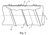
- Figure 1 Such an arrangement is shown in Figure 1 attached hereto.
- Such a design may also be provided with circumferentially extending ridges formed by plastically deforming the cross-sectional profile of the strip before it is wound and such ridges overlap and nest within each other such as to provide an inter-lock which resists both axial and circumferential loads placed on the finished structure.
- the above arrangement may be provided with an internal liner, the form of which will depend upon the application for which the tubular structure is intended but may comprise a roll-form and seam-welded tubular member.
- the inner liner may be pre-formed so as to provide a mandrel or core upon which the helically wound reinforcing strip is wound.
- GB2433453 discloses a manufacturing step associated with the type of tubular structure disclosed in GB 2280889 which causes the reinforcing strip itself to be plastically deformed to a diameter slightly smaller than that of the core or liner onto which it is to be wound such that the strip is, effectively, self locating and places the core under a small amount of pressure but not enough to cause buckling.
- Both the above designs must process the reinforcing strip such as to accommodate the variation in diameter that the strip has between the inner diameter and the outer diameter. This processing can be problematic and may induce undesirable stresses in the material.
- the nature of the overlapping ridges used in the above arrangements complicates the accurate location and interlocking of the ridges.
- An additional manufacturing step is required in order to cause the variation in diameter required and this introduces additional residual strain into the material which may be undesirable and may use up an unacceptable proportion proportion of the relatively limited ductility available in high strength materials, such as high tensile steel.
- the present invention provides a tubular article having a longitudinal axis X comprising inner and outer separate strips of spirally wound overlapping material each having a longitudinal axis L and first and second edges, characterised in that each strip comprises two or more longitudinally extending ridges, each of which extends along said longitudinally extending axis L in parallel to each other and in which said ridges each comprise asymmetric ridges having a leading edge forming a contact portion and wherein said leading edges are each in contact with each other and further comprising a non-contact trailing edge portion which are spaced from each other by an amount G".
- said contact portion comprises a portion of said ridge extending at an angle ⁇ ' relative to said longitudinal axis X and in that said trailing edge portions extend at an angle ⁇ " relative to said longitudinal axis X and wherein said angle ⁇ " is greater than said angle ⁇ '.
- said angle ⁇ " is greater than said angle ⁇ ' by 20 degrees or more.
- said contact portion comprises a portion of said ridge extending at an angle ⁇ ' of between 70 degrees to 110 degrees relative to said longitudinal axis X.
- said contact portion comprises a portion of said ridge extending substantially perpendicular to said longitudinal axis X.
- said trailing edge portions extend at an angle ⁇ " of between 20 degrees and 70 degrees relative to said longitudinal axis X.
- said trailing edge portions extend at an angle ⁇ " of substantially 45 degrees to said longitudinal axis X.
- said leading edge of said outer strip each face away from each other.
- said leading edge of said inner strip each face towards each other. It will be appreciated that one could reverse the above such that the said leading edge of said outer strip each face towards each other and the leading edge of said inner strip each face away from each other.
- the arrangement includes an inner gap G between adjacent inner strip edges.
- the arrangement includes a gap G2 between adjacent outer strip edges.
- the inner gap G lies at a position between the outer ridges.
- said outer gap G2 lies at a position between the inner ridges.
- said article includes an inner core around which said inner and outer strips are wound.
- said inner and outer strips have a natural radius of curvature less than the radius R" of the outer portion of the inner core.
- said inner and outer strips comprise material having a tensile strength of between 800 and 2000 GPa.
- said strips are each wound at an angle ⁇ to said longitudinal axis X.
- said angle ⁇ is between 4 and 54 degrees, whilst in another said angle ⁇ is between 4 and 12 degrees.
- said angle ⁇ is substantially 12 degrees.
- a method of manufacturing a tubular article having a longitudinal axis X comprising providing inner and outer strips characterised by the steps of forming a pair of longitudinally extending ridges, on said strip, each of said ridges being formed such as to extends along said longitudinally extending axis L in parallel to each other and forming said ridges as asymmetric ridges having a leading edge forming a contact portion and wherein said strips are wound in spirally wound overlapping relationship such that leading edges thereof are each in contact with each other and said trailing edge portions are wound such as to be distanced from each other by an amount G".
- a tubular strip for manufacture of a tubular article according to any one of claims 1 to 14 comprising a pair or longitudinally extending ridges, each of which extends along said longitudinally extending axis L in parallel to each other and in which said ridges each comprise asymmetric ridges having a leading edge forming a contact portion and further comprising a non-contact trailing edge portion.
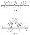
- the present invention comprises a tubular structure 10 having a longitudinal axis X and comprising inner and outer strips 12, 14 respectively.
- the strips 12, 14 each have a longitudinal axis L and include first and second edges 16, 18, 16', 18' and are each spirally wound around axis X at an angle ⁇ relative to the longitudinal axis X.
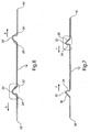
- Each strip 12, 14 comprises a pair of longitudinally extending ridges 20, 22, 20', 22', each of which extends along said longitudinal axis L in parallel to each other.
- each of the ridges comprise asymmetric ridges having a leading edge 24, 24' and a trailing edge 26, 26' where the leading edge(s) form a contact portion 28, 28' which are in contact with each other and a non-contact trailing edge portion 30, 30' which are spaced from each other by an amount G".
- the contact portion(s) 28, 28' comprises a portion of the ridges 12, 14, each of which extend at an angle ⁇ ' relative to said longitudinal axis X and the trailing edge portions 26, 26" extend at an angle ⁇ " relative so said longitudinal axis X and angle ⁇ " is greater than angle ⁇ '.
- ⁇ " is greater than ⁇ ' by an amount equal to or greater than 20 degrees.
- ⁇ ' is greater than ⁇ ' by an amount equal to or greater than 20 degrees.
- the angle ⁇ ' between 70 degrees and 110 degrees and possibly more depending on the degree of friction that exists between the two portions. What is most important is that the contact portions 28, 28' remain in contact with each other when axial load is placed on the article 10 which may, other than for the existence of the frictional or physical interference relationship at the contact point 28, 28' is such as to ensure the two leading edges remain in contact with each other when the structure 10 is manipulated such as to put a longitudinal strain thereon.
- the specific angle ⁇ ' will vary depending upon the properties of the material and the contact surface but that an angle of 90 degrees will optimise the degree of grip whilst still allowing the strips 12, 14 to be laid over each other.
- the preferred angle of ⁇ ' is such that the leading edges extend away from the surface of the strip perpendicular (90 degrees) to the longitudinal axis X.
- the trailing edges 26, 26' extend at an angle ⁇ " relative to the longitudinal axis X and, whilst the specific angle is less important than angle ⁇ ', the specific angle ⁇ " chosen depends partially on the degree of bending the strip material can accommodate and partially on the practicality of the amount of space available.
- leading edges 24, 24' on each strip can either face towards each other (arrow T) or away from each other (arrow A).
- the leading edges 24 of the inner strip 12 face towards each other whilst the leading edges 24' of the outer strip 14 face away from each other.
- This arrangement may be reversed such that the leading edges 24 of the inner strip 12 face away from each other whilst the leading edges 24' of the outer strip face towards each other.
- This reverse arrangement between strips 12, 14 is requires such that the inner and outer strips 12, 14 can be lain one on top of the other in staggered arrangement, as best seen in figure 4 .
- the staggering is equal to one pitch of the ridges 20, 20', 22, 22' such that a right hand RH inner ridge 20 fits under and within a left hand LH outer ridge 22 whilst a left hand LH inner ridge 22 will fit under and within a right hand RH outer ridge 22'.
- the inner and outer strips 12, 14 are, therefore, to some extent locked to each other by the interaction of the leading edges 24, 24' which arranged to be in close proximity and preferably in contact with each other once assembled. Indeed, the arrangement may be such as to provide a small interference fit between the two engaging surfaces at the contact portion 28, 28'.
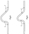
- gap G between edges of adjacent strips which allows for thermal expansion and manufacturing tolerances but which is sized such as to restrict to a minimum the axial distance over which a single layer of reinforcing layers 12, 14 are provided over the core or liner 30, best seen in figure 5 .
- Figure 5 provides a more detailed cross-sectional view of the ridge section and from which it will be appreciated that the bend radii R and location thereof of both the inner and the outer strips 12, 14 (which are shown in more detail in figures 8 and 9 ) are preferably selected such as to ensure appropriate gaps G' and G".
- Gap G" is provided on the trailing edge of the ridge and, preferably, extends from the peak 32 thereof and downwardly along the trailing edge portions 26, 26' themselves. The function of this gap is to provide some degree of flexibility in the finished tubular article itself 10 and, it will be appreciated, that the gap G" may be varied or indeed eliminated altogether if so desired. An arrangement without a gap G" would be more difficult to manufacture but would be more rigid.
- Gap G' is provided at the base 34 of the leading edge and provided merely to ensure a spacing between the two layers as they each transition between a substantially longitudinal direction (axis X) and a substantially transverse direction T. Such a gap G' also helps ensure that the two contacting surfaces of the inner and outer layers 12, 14 are placed in contact with each other as soon as possible after they exist their respective initial bends 36, 38 at the base 40, 42 of the leading edges.
- Figures 6 and 7 clearly illustrate the major differences between the inner 12 and outer 14 layers and from which it will further be appreciated that the bend radii R associated with the outer layer 14 must be larger than the bend radii associated with the inner layer such as to ensure the two sit comfortably one within the other.
- these figures illustrate very clearly the difference between the directions of orientation of the ridges 24, 24' for each of the inner 12 and outer 14 layers which, when displaced axially along axis X relative to each other by half a strip width will allow each layer to nestle next to each other, as shown, and without an excessive gap being formed therebetween.
- the method of manufacturing a tubular article (10) as described above and having a longitudinal axis X comprises the steps of: providing inner and outer strips (12,14); forming the pair or longitudinally extending ridges (20, 22, 20', 22'), on said strip, each of said ridges being formed such as to extend along said longitudinally extending axis L in parallel to each other and forming said ridges (20, 22, 20', 22') as asymmetric ridges having a leading edge (24, 24') forming a contact portion (28, 28') and winding said strips in spirally wound overlapping relationship such that leading edges (24, 24') thereof are each in contact with each other and said trailing edge portions (26, 26') are wound such as to be distanced from each other by an amount G".
- Figures 10 and 11 provide some comparison between the present invention (2 ridge Geometry with duplex/Docal Roll Properties and a number of other designs. It is desirable that the axial extension or global strain is not too great under internal pressure or it will lead to movement and possibly failure.
- Figure 10 compares the new design designated 2-rib with 3 prior art designs 135 and 185 and one design that is not prior art and has two layers but has only a single rib.
- Figure 11 compares the single rib or ridge with the 2-rib or ridge design. From these figures it will be appreciated that the new design equals or out-performs many of the prior art arrangements because the extension does not increase under pressure despite the fact that it comprises just two layers whereas the prior art comprises three layers.
- the present invention also employs a winding angle ⁇ of up to 30 degrees compared with the prior art arrangement which is typically just 4 degrees. This increase in winding angle alone increases the speed and efficiency of manufacture by a large factor (three in the case of the preferred configuration where the winding angle is 12 degrees). It is thought feasible that angles of up to 54 degrees may be achievable for certain applications and the present invention is deemed to cover such a range.
- the performance of the present invention in comparison with known strip profiles will now be discussed with reference to figures 10 and 11 above and 12 to 14 which disclose the known strip profiles.
- the present invention provides a 2 ridge geometry with Duplex S32205 / Docol Roll and is presented as such in the comparative performance tables and graphs. The comparison is with results for prior art configurations analysed under internal pressure loading.
- the two ridge geometry in the example of the present invention consists of two independent strips, helically wound around the liner at 12' approximately, creating a 2 layer strip cross-section. This configuration was analysed with Duplex S32205 / Docol Roll properties. Strip thickness is increased to 0.75mm. A section through the strip arrangement is shown in figure 4 attached hereto.
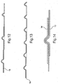
- the first prior art comparative example is referred to as the 135 geometry and consists of a single strip with 3 symmetric ridges, helically wound around the liner at 4'.
- the strip is "joggled" twice between the ridges, creating a 3 layer strip cross-section.
- This concept was analysed with both the 316L/M190 properties and the Duplex S32205 / Docol Roll properties. A section through the strip profile is shown in Figure 12 .
- the second comparative example is referred to as the 185 geometry and consists of a single strip with 3 asymmetric ridges, helically wound around the liner at 4'.
- the strip is "stepped" twice at the ridge locations, creating a 3 layer strip cross-section. This concept was analysed with Duplex S32205/Docol Roll properties. A section through the strip profile is shown in Figure 13 .
- the third comparative example is referred to as the Dreistern 185 geometry and consists of three independent strips, each with a single asymmetric ridge, helically wound at 4' around the liner, creating a three layer strip cross-section. This concept was analysed with Duplex S32205 / Docol Roll properties. A section through the strip profile is shown in Figure 14 .
- PEEQ Abaqus output
- FIG. 10 Comparison of the global axial strain against internal pressure for each configuration including the present study is illustrated in Figure 10 .
- the 2 ridge design is at least as good as other configurations in terms of axial stiffness. A higher contribution to the axial resistance from the strip layer due to the increase in winding angle may account for this.
- Figure 11 graphs a comparison of the axial separation between adjacent outer strip layers calculated in the single ridge Dreistern 185 geometry and the 2 ridge geometry under internal pressure. These two configurations are compared since they are the only ones to incorporate multiple independent strip layers. This graph indicates a much larger axial separation between the layers of the Dreistern 185 geometry, due to the lack of ridge interlock. Although a single ridge would reduce manufacturing complexity the extent of separation under single load is considered undesirable. This illustrates the effectiveness of the 2-ridge interlocking invention disclosed here.
- the 3D analysis of the Helipipe geometry has been performed using the Abaqus general purpose FEA code, version 6.10-1 [2]. All load cases are solved quasi-statically using the explicit dynamic solver.
- the explicit solver allows for all the possible contact interfaces which may arise during analysis to be generated in one single automatic contact definition.
- the explicit solver also typically has lower memory requirements than the implicit solver as the model size increases.
- the main advantage associated with the present invention is the elimination of the steps associated with the prior art arrangements and the elimination of the requirement to accommodate the change in diameter of the strip between the inner and the outer diameters thereof.
- the present invention achieved very comparable pressure performance without the requirement for the complex self-overlapping arrangement of the prior art.
- the performance of the present invention was also achieved with a more ductile grade of material than the prior art, as detailed below by reference to published data for commercial grades of high strength steel: Commercial Grade Minimum Tensile Strength MPa Minimum Elongation % Min Bend Radius (for forming) Ducol 1000DP 1000 7 2t M190, Ducol 1400M 1400 3 3t
Landscapes
- Engineering & Computer Science (AREA)
- General Engineering & Computer Science (AREA)
- Mechanical Engineering (AREA)
- Rigid Pipes And Flexible Pipes (AREA)
- Laminated Bodies (AREA)
- Tires In General (AREA)
- Materials For Medical Uses (AREA)
- Shaping Of Tube Ends By Bending Or Straightening (AREA)
Claims (19)
- Rohrförmiger Artikel (10) mit einer Längsachse X, umfassend innere und äußere separate Streifen (12, 14) aus spiralförmig gewundenem überlappendem Material, die jeweils ein Längsachse L und erste und zweite Kanten (16, 18, 16', 18') aufweisen, dadurch gekennzeichnet, dass jeder Streifen (12, 14) zwei oder mehrere sich in Längsrichtung erstreckende Erhöhungen (20, 22, 20', 22') aufweist, von welchen sich jede entlang der sich in Längsrichtung erstreckenden Achse L parallel zueinander erstreckt, und wobei die Erhöhungen (20, 22, 20', 22') jeweils asymmetrische Erhöhungen umfassen, die eine einen Kontaktabschnitt (28, 28') bildende Vorderflanke(24, 24') aufweisen und wobei die Vorderflanken (24, 24') jeweils in Kontakt miteinander sind und ferner einen kontaktfreien Rückflankenabschnitt (26, 26') umfassen welche voneinander um einen Betrag G" beabstandet sind.
- Rohrförmiger Artikel nach Anspruch 1, dadurch gekennzeichnet, dass der Kontaktabschnitt (28, 28') einen Abschnitt der Erhöhung (20, 22, 20', 22') umfasst, der sich in einem Winkel θ bezüglich der Längsachse X erstreckt, und dass sich die Rückflankenabschnitte (26, 26') in einem Winkel θ" bezüglich der Längsachse X erstrecken, und wobei der Winkel θ" größer als der Winkel θ' ist.
- Rohrförmiger Artikel (10) nach Anspruch 2, dadurch gekennzeichnet, dass der Winkel θ" um 20 Grad oder mehr größer als der Winkel θ' ist.
- Rohrförmiger Artikel nach Anspruch 1, dadurch gekennzeichnet, dass der Kontaktabschnitt (28, 28') einen Abschnitt der Erhöhung (20, 22, 20', 22') umfasst, der sich in einem Winkel θ' zwischen 70 Grad und 110 Grad bezüglich der Längsachse X erstreckt.
- Rohrförmiger Artikel (10) nach Anspruch 1, dadurch gekennzeichnet, dass der Kontaktabschnitt (28, 28') einen Abschnitt der Erhöhung (20, 22, 20', 22') umfasst, der sich im Wesentlichen rechtwinklig zur Längsachse X erstreckt.
- Rohrförmiger Artikel (10) nach einem der Ansprüche 1 bis 3, dadurch gekennzeichnet, dass sich die Rückflankenabschnitte (26, 26`) in einem Winkel θ" zwischen 20 und 70 Grad bezüglich der Längsachse X erstrecken.
- Rohrförmiger Artikel nach einem der Ansprüche 1 bis 3, dadurch gekennzeichnet, dass sich die Rückflankenabschnitte (26, 26') in einem Winkel θ" von im Wesentlichen 45 Grad zur Längsachse X erstrecken.
- Rohrförmiger Artikel nach einem der Ansprüche 1 bis 5, dadurch gekennzeichnet, dass die Vorderflanken (24') des äußeren Streifens (14) jeweils voneinander weg zeigen.
- Rohrförmiger Artikel nach einem der Ansprüche 1 bis 5, dadurch gekennzeichnet, dass die Vorderflanken (24) des inneren Streifens (12) jeweils zueinander zeigen.
- Rohrförmiger Artikel nach einem der Ansprüche 1 bis 5, dadurch gekennzeichnet, dass die Vorderflanken (24') des äußeren Streifens (14) jeweils zueinander zeigen.
- Rohrförmiger Artikel nach einem der Ansprüche 1 bis 5, dadurch gekennzeichnet, dass die Vorderflanken (24') des inneren Streifens (12) jeweils voneinander weg zeigen.
- Rohrförmiger Artikel nach einem der Ansprüche 1 bis 11, gekennzeichnet durch eine innere Lücke G zwischen den nebeneinander liegenden inneren Streifenkanten (16, 18).
- Rohrförmiger Artikel nach einem der Ansprüche 1 bis 2, gekennzeichnet durch eine Lücke G2 zwischen den nebeneinander liegenden äußeren Streifenkanten (16', 18').
- Rohrförmiger Artikel (10) nach einem der Ansprüche 1 bis 13, dadurch gekennzeichnet, dass die innere Lücke G an einer Position zwischen den äußeren Erhöhungen (20', 22') liegt.
- Rohrförmiger Artikel (10) nach einem der Ansprüche 1 bis 14, dadurch gekennzeichnet, dass eine äußere Lücke G2 an einer Position zwischen den inneren Erhöhungen (20, 22) liegt.
- Rohrförmiger Artikel (10) nach einem der Ansprüche 1 bis 15, gekennzeichnet durch einen inneren Kern (30), um welchen die inneren und äußeren Streifen (12, 14) gewunden sind.
- Rohrförmiger Artikel nach Anspruch 16, dadurch gekennzeichnet, dass die inneren und äußeren Streifen (12, 14) einen natürlichen Krümmungsradius aufweisen, der kleiner als der Radius R" des äußeren Abschnitts des inneren Kerns (30) ist.
- Verfahren zur Herstellung eines rohrförmigen Artikels (10) nach einem der Ansprüche 1 bis 17 und mit einer Längsachse X, umfassend das Bereitstellen innerer und äußerer Streifen (12, 14), gekennzeichnet durch die Schritte des Bildens der beiden sich in Längsrichtung erstreckenden Erhöhungen (20, 22, 20', 22') auf dem Streifen, wobei jede der Erhöhungen derart geformt ist, dass sie sich entlang der in Längsrichtung erstreckenden Achse L parallel zueinander erstrecken und des Bildens der Erhöhungen (20, 22, 20', 22') als asymmetrische Erhöhungen mit einer einen Kontaktabschnitt (28, 28') bildenden Vorderflanke (24, 24') und wobei die Streifen in spiralförmig gewundenem überlappendem Verhältnis gewunden sind, so dass die Vorderflanken (24, 24') davon jeweils in Kontakt miteinander sind und die Rückflankenabschnitte (26, 26') derart gewunden sind, dass sie voneinander um einen Betrag G" beabstandet sind.
- Paar rohrförmiger Streifen (12, 14), die jeweils eine Längsachse L aufweisen, zur Herstellung eines rohrförmigen Artikels nach einem der Ansprüche 1 bis 17, wobei die Streifen (12, 14) zwei sich in Längsrichtung erstreckende Erhöhungen (20, 22 oder 20', 22') aufweisen, von denen sich jede entlang der sich in Längsrichtung erstreckenden Achse L parallel zueinander erstrecken, und wobei die Erhöhungen (20, 22 oder 20', 22') jeweils asymmetrische Erhöhungen mit einer Vorderflanke (24 oder 24') und einem Rückflankenabschnitt (26 oder 26') aufweisen, wobei die Vorderflanken (24') des äußeren Streifens (14) jeweils weg voneinander zeigen, wobei die Vorderflanken (24) des inneren Streifens (12) jeweils zueinander zeigen, oder die Vorderflanken (24') des äußeren Streifens (14) jeweils zueinander zeigen und die Vorderflanken (24) des inneren Streifens (12) jeweils weg voneinander zeigen und wobei die Vorderflanken (24 oder 24') in einem Winkel angewinkelt sind, um einen Kontakt zwischen ihnen zu verursachen, wenn sie übereinander angeordnet sind, und wobei die Rückflankenabschnitte (26 oder 26') derart in einem Winkel angewinkelt sind, um eine Lücke G" zwischen ihnen zu erzeugen, wenn sie übereinander angeordnet sind.
Applications Claiming Priority (2)
| Application Number | Priority Date | Filing Date | Title |
|---|---|---|---|
| GB1118846.3A GB2496137B (en) | 2011-11-01 | 2011-11-01 | Tubular bodies and methods of forming same |
| PCT/GB2012/052719 WO2013064827A1 (en) | 2011-11-01 | 2012-10-31 | Tubular bodies and methods of forming same |
Publications (2)
| Publication Number | Publication Date |
|---|---|
| EP2776751A1 EP2776751A1 (de) | 2014-09-17 |
| EP2776751B1 true EP2776751B1 (de) | 2016-01-20 |
Family
ID=45375639
Family Applications (1)
| Application Number | Title | Priority Date | Filing Date |
|---|---|---|---|
| EP12795588.8A Active EP2776751B1 (de) | 2011-11-01 | 2012-10-31 | Röhrenförmige körper und herstellungsverfahren dafür |
Country Status (8)
| Country | Link |
|---|---|
| US (1) | US9689513B2 (de) |
| EP (1) | EP2776751B1 (de) |
| CN (1) | CN104011446B (de) |
| AP (1) | AP2014007667A0 (de) |
| ES (1) | ES2568919T3 (de) |
| GB (1) | GB2496137B (de) |
| RU (1) | RU2620859C2 (de) |
| WO (1) | WO2013064827A1 (de) |
Families Citing this family (2)
| Publication number | Priority date | Publication date | Assignee | Title |
|---|---|---|---|---|
| WO2012158412A1 (en) * | 2011-05-13 | 2012-11-22 | Deepflex Inc. | Reinforcement laminate having an alignment feature |
| GB2593146B (en) * | 2020-02-10 | 2022-09-07 | Sustainable Pipeline Systems Ltd | Pipeline sensing system |
Family Cites Families (22)
| Publication number | Priority date | Publication date | Assignee | Title |
|---|---|---|---|---|
| US3674056A (en) * | 1970-03-20 | 1972-07-04 | Wiremold Co | Scuff strip for tow-element helically wound tubing |
| US4196755A (en) * | 1977-09-19 | 1980-04-08 | Automation Industries, Inc. | Reinforced flexible duct with integral molded liner |
| US4486484A (en) * | 1982-09-28 | 1984-12-04 | Security Lumber & Supply Co. | Strip of flexible corrugated material |
| DE3540125C3 (de) * | 1985-11-13 | 1997-05-07 | Hahn Fritz Gmbh Co Kg | Verfahren und Vorrichtung zum Herstellen eines Wellrohres durch schraubenlinienförmiges Wickeln eines gewellten, dünnen Bandes, vorzugsweise eines Stahlbandes |
| JPH01279732A (ja) * | 1988-04-30 | 1989-11-10 | Nippon Steel Corp | 耐水素誘起割れ特性に優れた高強度鋼線 |
| GB2280889B (en) * | 1993-08-12 | 1998-04-01 | Royal Ordnance Plc | Hollow elongated or tubular bodies and their manufacture |
| US5645110A (en) * | 1994-12-01 | 1997-07-08 | Nobileau; Philippe | Flexible high pressure pipe |
| FR2749915B1 (fr) * | 1996-06-18 | 1998-09-04 | Westaflex Automobile | Tuyau etanche aux liquides |
| US5730188A (en) * | 1996-10-11 | 1998-03-24 | Wellstream, Inc. | Flexible conduit |
| JPH1182825A (ja) * | 1997-09-05 | 1999-03-26 | Tigers Polymer Corp | 伸縮性ホース |
| BR9916335A (pt) * | 1998-12-16 | 2001-09-11 | Nkt Flexibles Is | Tubo flexìvel blindado e uso do mesmo |
| CN1189128C (zh) * | 2000-02-25 | 2005-02-16 | 东拓工业株式会社 | 挠性软管 |
| JP2001254876A (ja) * | 2000-03-08 | 2001-09-21 | Totaku Kogyo Kk | 可撓性ホース |
| US6378561B1 (en) * | 2001-02-24 | 2002-04-30 | Tru-Flex Metal Hose Corp. | Self-sealing flexible metal hose |
| CA2624190C (en) * | 2002-09-09 | 2010-04-13 | Fisher & Paykel Healthcare Limited | Conduit and method of forming |
| US7766050B2 (en) * | 2003-11-28 | 2010-08-03 | Fisher & Paykel Healthcare Limited | Conduit and method of forming |
| JP2005180609A (ja) * | 2003-12-19 | 2005-07-07 | Totaku Industries Inc | 耐圧複合管 |
| GB0414837D0 (en) * | 2004-07-02 | 2004-08-04 | Booth John P | Improvements in or relating to tubular bodies and methods of forming same |
| GB2433453B (en) * | 2005-12-23 | 2010-08-11 | Iti Scotland Ltd | An apparatus for and method of manfacturing helically wound structures |
| GB0611058D0 (en) * | 2006-06-05 | 2006-07-12 | Iti Scotland Ltd | Tubular members and methods of forming same |
| GB0800256D0 (en) * | 2008-01-08 | 2008-02-13 | Iti Scotland Ltd | A winding apparatus for and method of manufacturing helically wound structures |
| DE102009043932A1 (de) * | 2009-09-02 | 2011-03-10 | Stükerjürgen, Ferdinand | Wickelrohr mit erhöhter Stabilität |
-
2011
- 2011-11-01 GB GB1118846.3A patent/GB2496137B/en active Active
-
2012
- 2012-10-31 US US14/355,483 patent/US9689513B2/en active Active
- 2012-10-31 WO PCT/GB2012/052719 patent/WO2013064827A1/en not_active Ceased
- 2012-10-31 AP AP2014007667A patent/AP2014007667A0/xx unknown
- 2012-10-31 RU RU2014122172A patent/RU2620859C2/ru active
- 2012-10-31 ES ES12795588.8T patent/ES2568919T3/es active Active
- 2012-10-31 EP EP12795588.8A patent/EP2776751B1/de active Active
- 2012-10-31 CN CN201280053609.4A patent/CN104011446B/zh active Active
Also Published As
| Publication number | Publication date |
|---|---|
| US9689513B2 (en) | 2017-06-27 |
| AP2014007667A0 (en) | 2014-05-31 |
| GB2496137A (en) | 2013-05-08 |
| RU2014122172A (ru) | 2015-12-10 |
| RU2620859C2 (ru) | 2017-05-30 |
| US20140318663A1 (en) | 2014-10-30 |
| CN104011446A (zh) | 2014-08-27 |
| WO2013064827A1 (en) | 2013-05-10 |
| GB2496137B (en) | 2015-09-02 |
| EP2776751A1 (de) | 2014-09-17 |
| GB201118846D0 (en) | 2011-12-14 |
| CN104011446B (zh) | 2016-03-30 |
| ES2568919T3 (es) | 2016-05-05 |
Similar Documents
| Publication | Publication Date | Title |
|---|---|---|
| US20060191311A1 (en) | Flexible pipe and method of manufacturing same | |
| US6006788A (en) | Flexible pipe with internal gasproof undulating metal tube | |
| US20110030834A1 (en) | multi-layered corrugated tubular article | |
| JP2009220182A (ja) | 多層パイプとその製造方法 | |
| JP2008523996A5 (de) | ||
| US20100139848A1 (en) | Production of tubular body comprising two or more layers of helically bended strips | |
| EP2776751B1 (de) | Röhrenförmige körper und herstellungsverfahren dafür | |
| US5158814A (en) | Flexible metal conduit and method of making the same | |
| US20120031521A1 (en) | Corrugated metal pipe | |
| AU2009203632B2 (en) | A tubular article | |
| US20250129879A1 (en) | Seismic pipe joint | |
| JP2023509326A (ja) | スパイラルチューブ | |
| CN113056338A (zh) | 具有螺旋缝的管以及用于生产具有螺旋缝的管的方法 | |
| EP4551854A2 (de) | Permeationssperre und herstellungsverfahren dafür | |
| EP3479917B1 (de) | Verfahren und vorrichtung zur umformung eines metallbandes | |
| RU2365453C1 (ru) | Способ изготовления многослойного сильфона | |
| UA65485A (en) | Method for manufacture of multi-layer tubes |
Legal Events
| Date | Code | Title | Description |
|---|---|---|---|
| PUAI | Public reference made under article 153(3) epc to a published international application that has entered the european phase |
Free format text: ORIGINAL CODE: 0009012 |
|
| 17P | Request for examination filed |
Effective date: 20140530 |
|
| AK | Designated contracting states |
Kind code of ref document: A1 Designated state(s): AL AT BE BG CH CY CZ DE DK EE ES FI FR GB GR HR HU IE IS IT LI LT LU LV MC MK MT NL NO PL PT RO RS SE SI SK SM TR |
|
| DAX | Request for extension of the european patent (deleted) | ||
| GRAP | Despatch of communication of intention to grant a patent |
Free format text: ORIGINAL CODE: EPIDOSNIGR1 |
|
| INTG | Intention to grant announced |
Effective date: 20150504 |
|
| RIN1 | Information on inventor provided before grant (corrected) |
Inventor name: STEVENSON, ANDREW |
|
| GRAR | Information related to intention to grant a patent recorded |
Free format text: ORIGINAL CODE: EPIDOSNIGR71 |
|
| GRAS | Grant fee paid |
Free format text: ORIGINAL CODE: EPIDOSNIGR3 |
|
| INTG | Intention to grant announced |
Effective date: 20151021 |
|
| GRAA | (expected) grant |
Free format text: ORIGINAL CODE: 0009210 |
|
| AK | Designated contracting states |
Kind code of ref document: B1 Designated state(s): AL AT BE BG CH CY CZ DE DK EE ES FI FR GB GR HR HU IE IS IT LI LT LU LV MC MK MT NL NO PL PT RO RS SE SI SK SM TR |
|
| REG | Reference to a national code |
Ref country code: GB Ref legal event code: FG4D |
|
| REG | Reference to a national code |
Ref country code: CH Ref legal event code: EP |
|
| REG | Reference to a national code |
Ref country code: IE Ref legal event code: FG4D |
|
| REG | Reference to a national code |
Ref country code: AT Ref legal event code: REF Ref document number: 771895 Country of ref document: AT Kind code of ref document: T Effective date: 20160215 |
|
| REG | Reference to a national code |
Ref country code: DE Ref legal event code: R096 Ref document number: 602012014215 Country of ref document: DE |
|
| REG | Reference to a national code |
Ref country code: SE Ref legal event code: TRGR |
|
| REG | Reference to a national code |
Ref country code: ES Ref legal event code: FG2A Ref document number: 2568919 Country of ref document: ES Kind code of ref document: T3 Effective date: 20160505 |
|
| REG | Reference to a national code |
Ref country code: LT Ref legal event code: MG4D Ref country code: NL Ref legal event code: MP Effective date: 20160120 |
|
| REG | Reference to a national code |
Ref country code: AT Ref legal event code: MK05 Ref document number: 771895 Country of ref document: AT Kind code of ref document: T Effective date: 20160120 |
|
| PG25 | Lapsed in a contracting state [announced via postgrant information from national office to epo] |
Ref country code: NL Free format text: LAPSE BECAUSE OF FAILURE TO SUBMIT A TRANSLATION OF THE DESCRIPTION OR TO PAY THE FEE WITHIN THE PRESCRIBED TIME-LIMIT Effective date: 20160120 |
|
| PG25 | Lapsed in a contracting state [announced via postgrant information from national office to epo] |
Ref country code: GR Free format text: LAPSE BECAUSE OF FAILURE TO SUBMIT A TRANSLATION OF THE DESCRIPTION OR TO PAY THE FEE WITHIN THE PRESCRIBED TIME-LIMIT Effective date: 20160421 Ref country code: FI Free format text: LAPSE BECAUSE OF FAILURE TO SUBMIT A TRANSLATION OF THE DESCRIPTION OR TO PAY THE FEE WITHIN THE PRESCRIBED TIME-LIMIT Effective date: 20160120 Ref country code: NO Free format text: LAPSE BECAUSE OF FAILURE TO SUBMIT A TRANSLATION OF THE DESCRIPTION OR TO PAY THE FEE WITHIN THE PRESCRIBED TIME-LIMIT Effective date: 20160420 Ref country code: HR Free format text: LAPSE BECAUSE OF FAILURE TO SUBMIT A TRANSLATION OF THE DESCRIPTION OR TO PAY THE FEE WITHIN THE PRESCRIBED TIME-LIMIT Effective date: 20160120 Ref country code: IT Free format text: LAPSE BECAUSE OF FAILURE TO SUBMIT A TRANSLATION OF THE DESCRIPTION OR TO PAY THE FEE WITHIN THE PRESCRIBED TIME-LIMIT Effective date: 20160120 |
|
| PG25 | Lapsed in a contracting state [announced via postgrant information from national office to epo] |
Ref country code: PL Free format text: LAPSE BECAUSE OF FAILURE TO SUBMIT A TRANSLATION OF THE DESCRIPTION OR TO PAY THE FEE WITHIN THE PRESCRIBED TIME-LIMIT Effective date: 20160120 Ref country code: LV Free format text: LAPSE BECAUSE OF FAILURE TO SUBMIT A TRANSLATION OF THE DESCRIPTION OR TO PAY THE FEE WITHIN THE PRESCRIBED TIME-LIMIT Effective date: 20160120 Ref country code: AT Free format text: LAPSE BECAUSE OF FAILURE TO SUBMIT A TRANSLATION OF THE DESCRIPTION OR TO PAY THE FEE WITHIN THE PRESCRIBED TIME-LIMIT Effective date: 20160120 Ref country code: IS Free format text: LAPSE BECAUSE OF FAILURE TO SUBMIT A TRANSLATION OF THE DESCRIPTION OR TO PAY THE FEE WITHIN THE PRESCRIBED TIME-LIMIT Effective date: 20160520 Ref country code: RS Free format text: LAPSE BECAUSE OF FAILURE TO SUBMIT A TRANSLATION OF THE DESCRIPTION OR TO PAY THE FEE WITHIN THE PRESCRIBED TIME-LIMIT Effective date: 20160120 Ref country code: LT Free format text: LAPSE BECAUSE OF FAILURE TO SUBMIT A TRANSLATION OF THE DESCRIPTION OR TO PAY THE FEE WITHIN THE PRESCRIBED TIME-LIMIT Effective date: 20160120 Ref country code: PT Free format text: LAPSE BECAUSE OF FAILURE TO SUBMIT A TRANSLATION OF THE DESCRIPTION OR TO PAY THE FEE WITHIN THE PRESCRIBED TIME-LIMIT Effective date: 20160520 |
|
| REG | Reference to a national code |
Ref country code: DE Ref legal event code: R097 Ref document number: 602012014215 Country of ref document: DE Ref country code: FR Ref legal event code: PLFP Year of fee payment: 5 |
|
| PG25 | Lapsed in a contracting state [announced via postgrant information from national office to epo] |
Ref country code: DK Free format text: LAPSE BECAUSE OF FAILURE TO SUBMIT A TRANSLATION OF THE DESCRIPTION OR TO PAY THE FEE WITHIN THE PRESCRIBED TIME-LIMIT Effective date: 20160120 Ref country code: EE Free format text: LAPSE BECAUSE OF FAILURE TO SUBMIT A TRANSLATION OF THE DESCRIPTION OR TO PAY THE FEE WITHIN THE PRESCRIBED TIME-LIMIT Effective date: 20160120 |
|
| PLBE | No opposition filed within time limit |
Free format text: ORIGINAL CODE: 0009261 |
|
| STAA | Information on the status of an ep patent application or granted ep patent |
Free format text: STATUS: NO OPPOSITION FILED WITHIN TIME LIMIT |
|
| PG25 | Lapsed in a contracting state [announced via postgrant information from national office to epo] |
Ref country code: CZ Free format text: LAPSE BECAUSE OF FAILURE TO SUBMIT A TRANSLATION OF THE DESCRIPTION OR TO PAY THE FEE WITHIN THE PRESCRIBED TIME-LIMIT Effective date: 20160120 Ref country code: SK Free format text: LAPSE BECAUSE OF FAILURE TO SUBMIT A TRANSLATION OF THE DESCRIPTION OR TO PAY THE FEE WITHIN THE PRESCRIBED TIME-LIMIT Effective date: 20160120 Ref country code: RO Free format text: LAPSE BECAUSE OF FAILURE TO SUBMIT A TRANSLATION OF THE DESCRIPTION OR TO PAY THE FEE WITHIN THE PRESCRIBED TIME-LIMIT Effective date: 20160120 Ref country code: SM Free format text: LAPSE BECAUSE OF FAILURE TO SUBMIT A TRANSLATION OF THE DESCRIPTION OR TO PAY THE FEE WITHIN THE PRESCRIBED TIME-LIMIT Effective date: 20160120 |
|
| 26N | No opposition filed |
Effective date: 20161021 |
|
| PG25 | Lapsed in a contracting state [announced via postgrant information from national office to epo] |
Ref country code: BE Free format text: LAPSE BECAUSE OF FAILURE TO SUBMIT A TRANSLATION OF THE DESCRIPTION OR TO PAY THE FEE WITHIN THE PRESCRIBED TIME-LIMIT Effective date: 20160120 |
|
| PG25 | Lapsed in a contracting state [announced via postgrant information from national office to epo] |
Ref country code: BG Free format text: LAPSE BECAUSE OF FAILURE TO SUBMIT A TRANSLATION OF THE DESCRIPTION OR TO PAY THE FEE WITHIN THE PRESCRIBED TIME-LIMIT Effective date: 20160420 Ref country code: SI Free format text: LAPSE BECAUSE OF FAILURE TO SUBMIT A TRANSLATION OF THE DESCRIPTION OR TO PAY THE FEE WITHIN THE PRESCRIBED TIME-LIMIT Effective date: 20160120 |
|
| REG | Reference to a national code |
Ref country code: CH Ref legal event code: PL |
|
| REG | Reference to a national code |
Ref country code: IE Ref legal event code: MM4A |
|
| PG25 | Lapsed in a contracting state [announced via postgrant information from national office to epo] |
Ref country code: CH Free format text: LAPSE BECAUSE OF NON-PAYMENT OF DUE FEES Effective date: 20161031 Ref country code: LI Free format text: LAPSE BECAUSE OF NON-PAYMENT OF DUE FEES Effective date: 20161031 |
|
| PG25 | Lapsed in a contracting state [announced via postgrant information from national office to epo] |
Ref country code: LU Free format text: LAPSE BECAUSE OF NON-PAYMENT OF DUE FEES Effective date: 20161031 |
|
| REG | Reference to a national code |
Ref country code: FR Ref legal event code: PLFP Year of fee payment: 6 |
|
| PG25 | Lapsed in a contracting state [announced via postgrant information from national office to epo] |
Ref country code: IE Free format text: LAPSE BECAUSE OF NON-PAYMENT OF DUE FEES Effective date: 20161031 |
|
| PG25 | Lapsed in a contracting state [announced via postgrant information from national office to epo] |
Ref country code: HU Free format text: LAPSE BECAUSE OF FAILURE TO SUBMIT A TRANSLATION OF THE DESCRIPTION OR TO PAY THE FEE WITHIN THE PRESCRIBED TIME-LIMIT; INVALID AB INITIO Effective date: 20121031 |
|
| PG25 | Lapsed in a contracting state [announced via postgrant information from national office to epo] |
Ref country code: MK Free format text: LAPSE BECAUSE OF FAILURE TO SUBMIT A TRANSLATION OF THE DESCRIPTION OR TO PAY THE FEE WITHIN THE PRESCRIBED TIME-LIMIT Effective date: 20160120 Ref country code: MC Free format text: LAPSE BECAUSE OF FAILURE TO SUBMIT A TRANSLATION OF THE DESCRIPTION OR TO PAY THE FEE WITHIN THE PRESCRIBED TIME-LIMIT Effective date: 20160120 Ref country code: MT Free format text: LAPSE BECAUSE OF NON-PAYMENT OF DUE FEES Effective date: 20161031 Ref country code: CY Free format text: LAPSE BECAUSE OF FAILURE TO SUBMIT A TRANSLATION OF THE DESCRIPTION OR TO PAY THE FEE WITHIN THE PRESCRIBED TIME-LIMIT Effective date: 20160120 |
|
| REG | Reference to a national code |
Ref country code: FR Ref legal event code: PLFP Year of fee payment: 7 |
|
| PG25 | Lapsed in a contracting state [announced via postgrant information from national office to epo] |
Ref country code: AL Free format text: LAPSE BECAUSE OF FAILURE TO SUBMIT A TRANSLATION OF THE DESCRIPTION OR TO PAY THE FEE WITHIN THE PRESCRIBED TIME-LIMIT Effective date: 20160120 |
|
| PGFP | Annual fee paid to national office [announced via postgrant information from national office to epo] |
Ref country code: DE Payment date: 20241010 Year of fee payment: 13 |
|
| PGFP | Annual fee paid to national office [announced via postgrant information from national office to epo] |
Ref country code: GB Payment date: 20241010 Year of fee payment: 13 |
|
| PGFP | Annual fee paid to national office [announced via postgrant information from national office to epo] |
Ref country code: FR Payment date: 20241010 Year of fee payment: 13 |
|
| PGFP | Annual fee paid to national office [announced via postgrant information from national office to epo] |
Ref country code: ES Payment date: 20241115 Year of fee payment: 13 |
|
| PGFP | Annual fee paid to national office [announced via postgrant information from national office to epo] |
Ref country code: SE Payment date: 20241015 Year of fee payment: 13 |
|
| PGFP | Annual fee paid to national office [announced via postgrant information from national office to epo] |
Ref country code: TR Payment date: 20241028 Year of fee payment: 13 |