EP2776751B1 - Tubular bodies and methods of forming same - Google Patents
Tubular bodies and methods of forming same Download PDFInfo
- Publication number
- EP2776751B1 EP2776751B1 EP12795588.8A EP12795588A EP2776751B1 EP 2776751 B1 EP2776751 B1 EP 2776751B1 EP 12795588 A EP12795588 A EP 12795588A EP 2776751 B1 EP2776751 B1 EP 2776751B1
- Authority
- EP
- European Patent Office
- Prior art keywords
- strip
- tubular article
- ridges
- angle
- longitudinal axis
- Prior art date
- Legal status (The legal status is an assumption and is not a legal conclusion. Google has not performed a legal analysis and makes no representation as to the accuracy of the status listed.)
- Active
Links
- 238000000034 method Methods 0.000 title description 8
- 239000000463 material Substances 0.000 claims description 17
- 238000004519 manufacturing process Methods 0.000 claims description 16
- 239000010410 layer Substances 0.000 description 30
- 238000004804 winding Methods 0.000 description 8
- 238000000926 separation method Methods 0.000 description 6
- 230000008901 benefit Effects 0.000 description 5
- 230000000052 comparative effect Effects 0.000 description 5
- 230000003014 reinforcing effect Effects 0.000 description 5
- 238000004458 analytical method Methods 0.000 description 4
- 229910000831 Steel Inorganic materials 0.000 description 3
- 230000006872 improvement Effects 0.000 description 3
- 230000008569 process Effects 0.000 description 3
- 239000010959 steel Substances 0.000 description 3
- 238000005452 bending Methods 0.000 description 2
- 230000008030 elimination Effects 0.000 description 2
- 238000003379 elimination reaction Methods 0.000 description 2
- 238000003466 welding Methods 0.000 description 2
- 239000004215 Carbon black (E152) Substances 0.000 description 1
- 230000004888 barrier function Effects 0.000 description 1
- 230000008859 change Effects 0.000 description 1
- 230000000694 effects Effects 0.000 description 1
- 239000012467 final product Substances 0.000 description 1
- 230000006870 function Effects 0.000 description 1
- 239000007789 gas Substances 0.000 description 1
- 229930195733 hydrocarbon Natural products 0.000 description 1
- 150000002430 hydrocarbons Chemical class 0.000 description 1
- 238000009434 installation Methods 0.000 description 1
- 230000003993 interaction Effects 0.000 description 1
- 239000012263 liquid product Substances 0.000 description 1
- 239000002356 single layer Substances 0.000 description 1
- 230000007704 transition Effects 0.000 description 1
- 230000035899 viability Effects 0.000 description 1
Images


Classifications
-
- B—PERFORMING OPERATIONS; TRANSPORTING
- B21—MECHANICAL METAL-WORKING WITHOUT ESSENTIALLY REMOVING MATERIAL; PUNCHING METAL
- B21C—MANUFACTURE OF METAL SHEETS, WIRE, RODS, TUBES OR PROFILES, OTHERWISE THAN BY ROLLING; AUXILIARY OPERATIONS USED IN CONNECTION WITH METAL-WORKING WITHOUT ESSENTIALLY REMOVING MATERIAL
- B21C37/00—Manufacture of metal sheets, bars, wire, tubes or like semi-manufactured products, not otherwise provided for; Manufacture of tubes of special shape
- B21C37/06—Manufacture of metal sheets, bars, wire, tubes or like semi-manufactured products, not otherwise provided for; Manufacture of tubes of special shape of tubes or metal hoses; Combined procedures for making tubes, e.g. for making multi-wall tubes
- B21C37/12—Making tubes or metal hoses with helically arranged seams
-
- F—MECHANICAL ENGINEERING; LIGHTING; HEATING; WEAPONS; BLASTING
- F16—ENGINEERING ELEMENTS AND UNITS; GENERAL MEASURES FOR PRODUCING AND MAINTAINING EFFECTIVE FUNCTIONING OF MACHINES OR INSTALLATIONS; THERMAL INSULATION IN GENERAL
- F16L—PIPES; JOINTS OR FITTINGS FOR PIPES; SUPPORTS FOR PIPES, CABLES OR PROTECTIVE TUBING; MEANS FOR THERMAL INSULATION IN GENERAL
- F16L9/00—Rigid pipes
- F16L9/02—Rigid pipes of metal
- F16L9/04—Reinforced pipes
- F16L9/042—Reinforced pipes the reinforcement comprising one or more layers of a helically wound cord, wire or strip
- F16L9/045—Reinforced pipes the reinforcement comprising one or more layers of a helically wound cord, wire or strip using profiled strips
-
- F—MECHANICAL ENGINEERING; LIGHTING; HEATING; WEAPONS; BLASTING
- F16—ENGINEERING ELEMENTS AND UNITS; GENERAL MEASURES FOR PRODUCING AND MAINTAINING EFFECTIVE FUNCTIONING OF MACHINES OR INSTALLATIONS; THERMAL INSULATION IN GENERAL
- F16L—PIPES; JOINTS OR FITTINGS FOR PIPES; SUPPORTS FOR PIPES, CABLES OR PROTECTIVE TUBING; MEANS FOR THERMAL INSULATION IN GENERAL
- F16L11/00—Hoses, i.e. flexible pipes
- F16L11/14—Hoses, i.e. flexible pipes made of rigid material, e.g. metal or hard plastics
- F16L11/16—Hoses, i.e. flexible pipes made of rigid material, e.g. metal or hard plastics wound from profiled strips or bands
-
- F—MECHANICAL ENGINEERING; LIGHTING; HEATING; WEAPONS; BLASTING
- F16—ENGINEERING ELEMENTS AND UNITS; GENERAL MEASURES FOR PRODUCING AND MAINTAINING EFFECTIVE FUNCTIONING OF MACHINES OR INSTALLATIONS; THERMAL INSULATION IN GENERAL
- F16L—PIPES; JOINTS OR FITTINGS FOR PIPES; SUPPORTS FOR PIPES, CABLES OR PROTECTIVE TUBING; MEANS FOR THERMAL INSULATION IN GENERAL
- F16L9/00—Rigid pipes
- F16L9/02—Rigid pipes of metal
- F16L9/04—Reinforced pipes
-
- F—MECHANICAL ENGINEERING; LIGHTING; HEATING; WEAPONS; BLASTING
- F16—ENGINEERING ELEMENTS AND UNITS; GENERAL MEASURES FOR PRODUCING AND MAINTAINING EFFECTIVE FUNCTIONING OF MACHINES OR INSTALLATIONS; THERMAL INSULATION IN GENERAL
- F16L—PIPES; JOINTS OR FITTINGS FOR PIPES; SUPPORTS FOR PIPES, CABLES OR PROTECTIVE TUBING; MEANS FOR THERMAL INSULATION IN GENERAL
- F16L9/00—Rigid pipes
- F16L9/16—Rigid pipes wound from sheets or strips, with or without reinforcement
-
- Y—GENERAL TAGGING OF NEW TECHNOLOGICAL DEVELOPMENTS; GENERAL TAGGING OF CROSS-SECTIONAL TECHNOLOGIES SPANNING OVER SEVERAL SECTIONS OF THE IPC; TECHNICAL SUBJECTS COVERED BY FORMER USPC CROSS-REFERENCE ART COLLECTIONS [XRACs] AND DIGESTS
- Y10—TECHNICAL SUBJECTS COVERED BY FORMER USPC
- Y10T—TECHNICAL SUBJECTS COVERED BY FORMER US CLASSIFICATION
- Y10T29/00—Metal working
- Y10T29/49—Method of mechanical manufacture
- Y10T29/49826—Assembling or joining
Definitions
- This invention relates to a tubular bodies and methods of forming same, and relates more particularly but not exclusively to the production of pipes for use in systems such as pipelines for carrying hydrocarbon, gas or liquid products under pressure.
- GB2280889 discloses a method of forming a hollow elongated or tubular body and comprises helically winding at least one strip of material in self-overlapping fashion to provide a multi- layer tubular structure.
- the strip is pre-formed to provide a transverse cross-section having at least one step which, in each convolution of the strip accommodates the overlapping portion of the next convolution.
- a tubular body having a wall thickness formed of a plurality of laps may thus be continuously made from a single strip of material, the wall thickness generally being one strip thickness greater than the number of steps formed in the cross-section of the strip.
- Figure 1 Such an arrangement is shown in Figure 1 attached hereto.
- Such a design may also be provided with circumferentially extending ridges formed by plastically deforming the cross-sectional profile of the strip before it is wound and such ridges overlap and nest within each other such as to provide an inter-lock which resists both axial and circumferential loads placed on the finished structure.
- the above arrangement may be provided with an internal liner, the form of which will depend upon the application for which the tubular structure is intended but may comprise a roll-form and seam-welded tubular member.
- the inner liner may be pre-formed so as to provide a mandrel or core upon which the helically wound reinforcing strip is wound.
- GB2433453 discloses a manufacturing step associated with the type of tubular structure disclosed in GB 2280889 which causes the reinforcing strip itself to be plastically deformed to a diameter slightly smaller than that of the core or liner onto which it is to be wound such that the strip is, effectively, self locating and places the core under a small amount of pressure but not enough to cause buckling.
- Both the above designs must process the reinforcing strip such as to accommodate the variation in diameter that the strip has between the inner diameter and the outer diameter. This processing can be problematic and may induce undesirable stresses in the material.
- the nature of the overlapping ridges used in the above arrangements complicates the accurate location and interlocking of the ridges.
- An additional manufacturing step is required in order to cause the variation in diameter required and this introduces additional residual strain into the material which may be undesirable and may use up an unacceptable proportion proportion of the relatively limited ductility available in high strength materials, such as high tensile steel.
- the present invention provides a tubular article having a longitudinal axis X comprising inner and outer separate strips of spirally wound overlapping material each having a longitudinal axis L and first and second edges, characterised in that each strip comprises two or more longitudinally extending ridges, each of which extends along said longitudinally extending axis L in parallel to each other and in which said ridges each comprise asymmetric ridges having a leading edge forming a contact portion and wherein said leading edges are each in contact with each other and further comprising a non-contact trailing edge portion which are spaced from each other by an amount G".
- said contact portion comprises a portion of said ridge extending at an angle ⁇ ' relative to said longitudinal axis X and in that said trailing edge portions extend at an angle ⁇ " relative to said longitudinal axis X and wherein said angle ⁇ " is greater than said angle ⁇ '.
- said angle ⁇ " is greater than said angle ⁇ ' by 20 degrees or more.
- said contact portion comprises a portion of said ridge extending at an angle ⁇ ' of between 70 degrees to 110 degrees relative to said longitudinal axis X.
- said contact portion comprises a portion of said ridge extending substantially perpendicular to said longitudinal axis X.
- said trailing edge portions extend at an angle ⁇ " of between 20 degrees and 70 degrees relative to said longitudinal axis X.
- said trailing edge portions extend at an angle ⁇ " of substantially 45 degrees to said longitudinal axis X.
- said leading edge of said outer strip each face away from each other.
- said leading edge of said inner strip each face towards each other. It will be appreciated that one could reverse the above such that the said leading edge of said outer strip each face towards each other and the leading edge of said inner strip each face away from each other.
- the arrangement includes an inner gap G between adjacent inner strip edges.
- the arrangement includes a gap G2 between adjacent outer strip edges.
- the inner gap G lies at a position between the outer ridges.
- said outer gap G2 lies at a position between the inner ridges.
- said article includes an inner core around which said inner and outer strips are wound.
- said inner and outer strips have a natural radius of curvature less than the radius R" of the outer portion of the inner core.
- said inner and outer strips comprise material having a tensile strength of between 800 and 2000 GPa.
- said strips are each wound at an angle ⁇ to said longitudinal axis X.
- said angle ⁇ is between 4 and 54 degrees, whilst in another said angle ⁇ is between 4 and 12 degrees.
- said angle ⁇ is substantially 12 degrees.
- a method of manufacturing a tubular article having a longitudinal axis X comprising providing inner and outer strips characterised by the steps of forming a pair of longitudinally extending ridges, on said strip, each of said ridges being formed such as to extends along said longitudinally extending axis L in parallel to each other and forming said ridges as asymmetric ridges having a leading edge forming a contact portion and wherein said strips are wound in spirally wound overlapping relationship such that leading edges thereof are each in contact with each other and said trailing edge portions are wound such as to be distanced from each other by an amount G".
- a tubular strip for manufacture of a tubular article according to any one of claims 1 to 14 comprising a pair or longitudinally extending ridges, each of which extends along said longitudinally extending axis L in parallel to each other and in which said ridges each comprise asymmetric ridges having a leading edge forming a contact portion and further comprising a non-contact trailing edge portion.
- the present invention comprises a tubular structure 10 having a longitudinal axis X and comprising inner and outer strips 12, 14 respectively.
- the strips 12, 14 each have a longitudinal axis L and include first and second edges 16, 18, 16', 18' and are each spirally wound around axis X at an angle ⁇ relative to the longitudinal axis X.
- Each strip 12, 14 comprises a pair of longitudinally extending ridges 20, 22, 20', 22', each of which extends along said longitudinal axis L in parallel to each other.
- each of the ridges comprise asymmetric ridges having a leading edge 24, 24' and a trailing edge 26, 26' where the leading edge(s) form a contact portion 28, 28' which are in contact with each other and a non-contact trailing edge portion 30, 30' which are spaced from each other by an amount G".
- the contact portion(s) 28, 28' comprises a portion of the ridges 12, 14, each of which extend at an angle ⁇ ' relative to said longitudinal axis X and the trailing edge portions 26, 26" extend at an angle ⁇ " relative so said longitudinal axis X and angle ⁇ " is greater than angle ⁇ '.
- ⁇ " is greater than ⁇ ' by an amount equal to or greater than 20 degrees.
- ⁇ ' is greater than ⁇ ' by an amount equal to or greater than 20 degrees.
- the angle ⁇ ' between 70 degrees and 110 degrees and possibly more depending on the degree of friction that exists between the two portions. What is most important is that the contact portions 28, 28' remain in contact with each other when axial load is placed on the article 10 which may, other than for the existence of the frictional or physical interference relationship at the contact point 28, 28' is such as to ensure the two leading edges remain in contact with each other when the structure 10 is manipulated such as to put a longitudinal strain thereon.
- the specific angle ⁇ ' will vary depending upon the properties of the material and the contact surface but that an angle of 90 degrees will optimise the degree of grip whilst still allowing the strips 12, 14 to be laid over each other.
- the preferred angle of ⁇ ' is such that the leading edges extend away from the surface of the strip perpendicular (90 degrees) to the longitudinal axis X.
- the trailing edges 26, 26' extend at an angle ⁇ " relative to the longitudinal axis X and, whilst the specific angle is less important than angle ⁇ ', the specific angle ⁇ " chosen depends partially on the degree of bending the strip material can accommodate and partially on the practicality of the amount of space available.
- leading edges 24, 24' on each strip can either face towards each other (arrow T) or away from each other (arrow A).
- the leading edges 24 of the inner strip 12 face towards each other whilst the leading edges 24' of the outer strip 14 face away from each other.
- This arrangement may be reversed such that the leading edges 24 of the inner strip 12 face away from each other whilst the leading edges 24' of the outer strip face towards each other.
- This reverse arrangement between strips 12, 14 is requires such that the inner and outer strips 12, 14 can be lain one on top of the other in staggered arrangement, as best seen in figure 4 .
- the staggering is equal to one pitch of the ridges 20, 20', 22, 22' such that a right hand RH inner ridge 20 fits under and within a left hand LH outer ridge 22 whilst a left hand LH inner ridge 22 will fit under and within a right hand RH outer ridge 22'.
- the inner and outer strips 12, 14 are, therefore, to some extent locked to each other by the interaction of the leading edges 24, 24' which arranged to be in close proximity and preferably in contact with each other once assembled. Indeed, the arrangement may be such as to provide a small interference fit between the two engaging surfaces at the contact portion 28, 28'.
- gap G between edges of adjacent strips which allows for thermal expansion and manufacturing tolerances but which is sized such as to restrict to a minimum the axial distance over which a single layer of reinforcing layers 12, 14 are provided over the core or liner 30, best seen in figure 5 .
- Figure 5 provides a more detailed cross-sectional view of the ridge section and from which it will be appreciated that the bend radii R and location thereof of both the inner and the outer strips 12, 14 (which are shown in more detail in figures 8 and 9 ) are preferably selected such as to ensure appropriate gaps G' and G".
- Gap G" is provided on the trailing edge of the ridge and, preferably, extends from the peak 32 thereof and downwardly along the trailing edge portions 26, 26' themselves. The function of this gap is to provide some degree of flexibility in the finished tubular article itself 10 and, it will be appreciated, that the gap G" may be varied or indeed eliminated altogether if so desired. An arrangement without a gap G" would be more difficult to manufacture but would be more rigid.
- Gap G' is provided at the base 34 of the leading edge and provided merely to ensure a spacing between the two layers as they each transition between a substantially longitudinal direction (axis X) and a substantially transverse direction T. Such a gap G' also helps ensure that the two contacting surfaces of the inner and outer layers 12, 14 are placed in contact with each other as soon as possible after they exist their respective initial bends 36, 38 at the base 40, 42 of the leading edges.
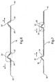
- Figures 6 and 7 clearly illustrate the major differences between the inner 12 and outer 14 layers and from which it will further be appreciated that the bend radii R associated with the outer layer 14 must be larger than the bend radii associated with the inner layer such as to ensure the two sit comfortably one within the other.
- these figures illustrate very clearly the difference between the directions of orientation of the ridges 24, 24' for each of the inner 12 and outer 14 layers which, when displaced axially along axis X relative to each other by half a strip width will allow each layer to nestle next to each other, as shown, and without an excessive gap being formed therebetween.
- the method of manufacturing a tubular article (10) as described above and having a longitudinal axis X comprises the steps of: providing inner and outer strips (12,14); forming the pair or longitudinally extending ridges (20, 22, 20', 22'), on said strip, each of said ridges being formed such as to extend along said longitudinally extending axis L in parallel to each other and forming said ridges (20, 22, 20', 22') as asymmetric ridges having a leading edge (24, 24') forming a contact portion (28, 28') and winding said strips in spirally wound overlapping relationship such that leading edges (24, 24') thereof are each in contact with each other and said trailing edge portions (26, 26') are wound such as to be distanced from each other by an amount G".
- Figures 10 and 11 provide some comparison between the present invention (2 ridge Geometry with duplex/Docal Roll Properties and a number of other designs. It is desirable that the axial extension or global strain is not too great under internal pressure or it will lead to movement and possibly failure.
- Figure 10 compares the new design designated 2-rib with 3 prior art designs 135 and 185 and one design that is not prior art and has two layers but has only a single rib.
- Figure 11 compares the single rib or ridge with the 2-rib or ridge design. From these figures it will be appreciated that the new design equals or out-performs many of the prior art arrangements because the extension does not increase under pressure despite the fact that it comprises just two layers whereas the prior art comprises three layers.
- the present invention also employs a winding angle ⁇ of up to 30 degrees compared with the prior art arrangement which is typically just 4 degrees. This increase in winding angle alone increases the speed and efficiency of manufacture by a large factor (three in the case of the preferred configuration where the winding angle is 12 degrees). It is thought feasible that angles of up to 54 degrees may be achievable for certain applications and the present invention is deemed to cover such a range.
- the performance of the present invention in comparison with known strip profiles will now be discussed with reference to figures 10 and 11 above and 12 to 14 which disclose the known strip profiles.
- the present invention provides a 2 ridge geometry with Duplex S32205 / Docol Roll and is presented as such in the comparative performance tables and graphs. The comparison is with results for prior art configurations analysed under internal pressure loading.
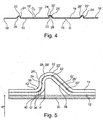
- the two ridge geometry in the example of the present invention consists of two independent strips, helically wound around the liner at 12' approximately, creating a 2 layer strip cross-section. This configuration was analysed with Duplex S32205 / Docol Roll properties. Strip thickness is increased to 0.75mm. A section through the strip arrangement is shown in figure 4 attached hereto.
- the first prior art comparative example is referred to as the 135 geometry and consists of a single strip with 3 symmetric ridges, helically wound around the liner at 4'.
- the strip is "joggled" twice between the ridges, creating a 3 layer strip cross-section.
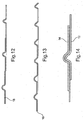
- This concept was analysed with both the 316L/M190 properties and the Duplex S32205 / Docol Roll properties. A section through the strip profile is shown in Figure 12 .
- the second comparative example is referred to as the 185 geometry and consists of a single strip with 3 asymmetric ridges, helically wound around the liner at 4'.
- the strip is "stepped" twice at the ridge locations, creating a 3 layer strip cross-section. This concept was analysed with Duplex S32205/Docol Roll properties. A section through the strip profile is shown in Figure 13 .
- the third comparative example is referred to as the Dreistern 185 geometry and consists of three independent strips, each with a single asymmetric ridge, helically wound at 4' around the liner, creating a three layer strip cross-section. This concept was analysed with Duplex S32205 / Docol Roll properties. A section through the strip profile is shown in Figure 14 .
- PEEQ Abaqus output
- FIG. 10 Comparison of the global axial strain against internal pressure for each configuration including the present study is illustrated in Figure 10 .
- the 2 ridge design is at least as good as other configurations in terms of axial stiffness. A higher contribution to the axial resistance from the strip layer due to the increase in winding angle may account for this.
- Figure 11 graphs a comparison of the axial separation between adjacent outer strip layers calculated in the single ridge Dreistern 185 geometry and the 2 ridge geometry under internal pressure. These two configurations are compared since they are the only ones to incorporate multiple independent strip layers. This graph indicates a much larger axial separation between the layers of the Dreistern 185 geometry, due to the lack of ridge interlock. Although a single ridge would reduce manufacturing complexity the extent of separation under single load is considered undesirable. This illustrates the effectiveness of the 2-ridge interlocking invention disclosed here.
- the 3D analysis of the Helipipe geometry has been performed using the Abaqus general purpose FEA code, version 6.10-1 [2]. All load cases are solved quasi-statically using the explicit dynamic solver.
- the explicit solver allows for all the possible contact interfaces which may arise during analysis to be generated in one single automatic contact definition.
- the explicit solver also typically has lower memory requirements than the implicit solver as the model size increases.
- the main advantage associated with the present invention is the elimination of the steps associated with the prior art arrangements and the elimination of the requirement to accommodate the change in diameter of the strip between the inner and the outer diameters thereof.
- the present invention achieved very comparable pressure performance without the requirement for the complex self-overlapping arrangement of the prior art.
- the performance of the present invention was also achieved with a more ductile grade of material than the prior art, as detailed below by reference to published data for commercial grades of high strength steel: Commercial Grade Minimum Tensile Strength MPa Minimum Elongation % Min Bend Radius (for forming) Ducol 1000DP 1000 7 2t M190, Ducol 1400M 1400 3 3t
Description
- This invention relates to a tubular bodies and methods of forming same, and relates more particularly but not exclusively to the production of pipes for use in systems such as pipelines for carrying hydrocarbon, gas or liquid products under pressure.
- Presently, it is well known to form pipelines from sections of pipe which have each been roll formed into tubular structures from flat strip or plate and seam welded in a pipe mill before being butt welded to each other in the field to form the finished pipeline. The viability of such pipes is limited by the economics of the materials being used and the weight of the final product which must be transported and moved into position, often in very difficult circumstances as well as the issues of final assembly. Final assembly typically requires a welding team of up to thirty welders to manually weld fixed segments of pipeline together and a support team of up to two hundred people is often needed in addition. The logistics associated with moving and caring for such large numbers of people in what can often be very remote locations can be prohibitively expensive and complex. Still further, such pipes are inherently rigid and straight and navigation of even undulating terrain usually requires specific bend stations which force bends of up to40 x the pipeline diameter into rigid sections and return them for welding into the pipe line. This is a manual process which has not changed for 75 years. The context of the process proposed here is that it is suitable for automation and reduces or eliminates the need for bend stations.
-
GB2280889 Figure 1 attached hereto. Such a design may also be provided with circumferentially extending ridges formed by plastically deforming the cross-sectional profile of the strip before it is wound and such ridges overlap and nest within each other such as to provide an inter-lock which resists both axial and circumferential loads placed on the finished structure. - The above arrangement may be provided with an internal liner, the form of which will depend upon the application for which the tubular structure is intended but may comprise a roll-form and seam-welded tubular member. In the fabrication of such a tubular structure, the inner liner may be pre-formed so as to provide a mandrel or core upon which the helically wound reinforcing strip is wound.
-
GB2433453 GB 2280889 - Both the above designs must process the reinforcing strip such as to accommodate the variation in diameter that the strip has between the inner diameter and the outer diameter. This processing can be problematic and may induce undesirable stresses in the material. In addition, the nature of the overlapping ridges used in the above arrangements complicates the accurate location and interlocking of the ridges. An additional manufacturing step is required in order to cause the variation in diameter required and this introduces additional residual strain into the material which may be undesirable and may use up an unacceptable proportion proportion of the relatively limited ductility available in high strength materials, such as high tensile steel.
- Whilst both the above arrangements provide acceptable solutions to the problem of manufacturing tubular structures, a further improvement has now been found that lends itself to the production of such tubular structures and it is to this improvement that the present application is directed.
-
Document DE 10 2009 043932 discloses also a similar tubular article. - Accordingly, the present invention provides a tubular article having a longitudinal axis X comprising inner and outer separate strips of spirally wound overlapping material each having a longitudinal axis L and first and second edges, characterised in that each strip comprises two or more longitudinally extending ridges, each of which extends along said longitudinally extending axis L in parallel to each other and in which said ridges each comprise asymmetric ridges having a leading edge forming a contact portion and wherein said leading edges are each in contact with each other and further comprising a non-contact trailing edge portion which are spaced from each other by an amount G".
- Preferably, said contact portion comprises a portion of said ridge extending at an angle θ' relative to said longitudinal axis X and in that said trailing edge portions extend at an angle θ" relative to said longitudinal axis X and wherein said angle θ" is greater than said angle θ'.
- Advantageously, said angle θ" is greater than said angle θ' by 20 degrees or more.
- In one arrangement, said contact portion comprises a portion of said ridge extending at an angle θ' of between 70 degrees to 110 degrees relative to said longitudinal axis X.
- Alternatively, said contact portion comprises a portion of said ridge extending substantially perpendicular to said longitudinal axis X.
- Advantageously, said trailing edge portions extend at an angle θ" of between 20 degrees and 70 degrees relative to said longitudinal axis X.
- Preferably, said trailing edge portions extend at an angle θ" of substantially 45 degrees to said longitudinal axis X.
- In one arrangement, said leading edge of said outer strip each face away from each other.
- In one arrangement, said leading edge of said inner strip each face towards each other. It will be appreciated that one could reverse the above such that the said leading edge of said outer strip each face towards each other and the leading edge of said inner strip each face away from each other.
- Preferably, the arrangement includes an inner gap G between adjacent inner strip edges.
- Advantageously, the arrangement includes a gap G2 between adjacent outer strip edges.
- Preferably, the inner gap G lies at a position between the outer ridges.
- Advantageously, said outer gap G2 lies at a position between the inner ridges.
- Preferably, said article includes an inner core around which said inner and outer strips are wound.
- Advantageously, said inner and outer strips have a natural radius of curvature less than the radius R" of the outer portion of the inner core.
- In a typical arrangement, said inner and outer strips comprise material having a tensile strength of between 800 and 2000 GPa.
- Preferably, said strips are each wound at an angle θ to said longitudinal axis X. In one arrangement said angle θ is between 4 and 54 degrees, whilst in another said angle θ is between 4 and 12 degrees. In a particular arrangement, said angle θ is substantially 12 degrees.
- According to another aspect of the present invention, there is provided a method of manufacturing a tubular article having a longitudinal axis X comprising providing inner and outer strips characterised by the steps of forming a pair of longitudinally extending ridges, on said strip, each of said ridges being formed such as to extends along said longitudinally extending axis L in parallel to each other and forming said ridges as asymmetric ridges having a leading edge forming a contact portion and wherein said strips are wound in spirally wound overlapping relationship such that leading edges thereof are each in contact with each other and said trailing edge portions are wound such as to be distanced from each other by an amount G".
- According to a further aspect of the present invention there is provided a tubular strip for manufacture of a tubular article according to any one of
claims 1 to 14 comprising a pair or longitudinally extending ridges, each of which extends along said longitudinally extending axis L in parallel to each other and in which said ridges each comprise asymmetric ridges having a leading edge forming a contact portion and further comprising a non-contact trailing edge portion. - The present invention will now be more particularly described by way of example only with reference to the accompanying drawings, in which:
-
Figures 1 and 2 are illustrative of the prior art tubular bodies; -
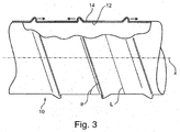
Figure 3 is a partially cut-away view of the tubular body according to the present invention; -
Figure 4 is a cross-sectional view of an overlapping portion of the tubular body offigure 3 ; -
Figure 5 is an expanded view of a ridge portion offigure 4 and illustrates in detail the interrelationship between the inner and outer ridges; -
Figure 6 is a cross-sectional view of the outer layer of strip shown infigures 3 to 5 ; -
Figure 7 is a cross-sectional view of the inner layer of strip shown infigures 3 to 5 -
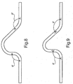
Figures 8 and 9 are detailed cross-sectional views of the outer and inner ridges as shown in the above-mentioned figures; -
Figure 10 is a graph of global axial strain against internal pressure for a number of designs, one of which is the present invention; -
Figure 11 is a graph of Outer Strip Axial Separation against Pressure for two designs; and -
Figures 12 to 14 are cross-sectional views of three different strip profiles used in the comparative numerical modelling to characterise behaviour. - Referring now to the drawings in general but more particularly to
figures 3 to 5 , the present invention comprises atubular structure 10 having a longitudinal axis X and comprising inner andouter strips strips second edges strip ridges edge trailing edge 26, 26' where the leading edge(s) form a contact portion 28, 28' which are in contact with each other and a non-contacttrailing edge portion 30, 30' which are spaced from each other by an amount G". The advantages associated with this arrangement will be explained later herein with reference tofigure 5 . The contact portion(s) 28, 28' comprises a portion of theridges trailing edge portions article 10 which may, other than for the existence of the frictional or physical interference relationship at the contact point 28, 28' is such as to ensure the two leading edges remain in contact with each other when thestructure 10 is manipulated such as to put a longitudinal strain thereon. The skilled reader will appreciate that the specific angle θ' will vary depending upon the properties of the material and the contact surface but that an angle of 90 degrees will optimise the degree of grip whilst still allowing thestrips edges 26, 26' extend at an angle θ" relative to the longitudinal axis X and, whilst the specific angle is less important than angle θ', the specific angle θ" chosen depends partially on the degree of bending the strip material can accommodate and partially on the practicality of the amount of space available. In practice, it has been found that an angle of between 20 degrees and 70 degrees relative to axis X is appropriate. In the specific example of the drawings, an angle θ" has been chosen as this gives a good compromise between reduced material damage in bending and a compact ridge design. Other angles will present themselves to those skilled in the art. - With reference to
figures 3 ,4 ,6 and 7 , it will be appreciated that the leadingedges edges 24 of theinner strip 12 face towards each other whilst the leadingedges 24' of theouter strip 14 face away from each other. This arrangement may be reversed such that the leadingedges 24 of theinner strip 12 face away from each other whilst the leadingedges 24' of the outer strip face towards each other. This reverse arrangement betweenstrips outer strips figure 4 . From this figure, it will be appreciated that the staggering is equal to one pitch of theridges inner ridge 20 fits under and within a left hand LHouter ridge 22 whilst a left hand LHinner ridge 22 will fit under and within a right hand RH outer ridge 22'. The inner andouter strips leading edges figure 4 is a gap G between edges of adjacent strips which allows for thermal expansion and manufacturing tolerances but which is sized such as to restrict to a minimum the axial distance over which a single layer of reinforcinglayers liner 30, best seen infigure 5 . -
Figure 5 provides a more detailed cross-sectional view of the ridge section and from which it will be appreciated that the bend radii R and location thereof of both the inner and theouter strips 12, 14 (which are shown in more detail infigures 8 and 9 ) are preferably selected such as to ensure appropriate gaps G' and G". Gap G" is provided on the trailing edge of the ridge and, preferably, extends from the peak 32 thereof and downwardly along the trailingedge portions 26, 26' themselves. The function of this gap is to provide some degree of flexibility in the finished tubular article itself 10 and, it will be appreciated, that the gap G" may be varied or indeed eliminated altogether if so desired. An arrangement without a gap G" would be more difficult to manufacture but would be more rigid. An arrangement with a greater gap G" would be more easily manufactured as tolerances would be lower but would be more flexible. Either arrangement or something between the two would be appropriate for different arrangements and the present design may be modified to suit the installation and operational requirements for flexibility. Gap G' is provided at the base 34 of the leading edge and provided merely to ensure a spacing between the two layers as they each transition between a substantially longitudinal direction (axis X) and a substantially transverse direction T. Such a gap G' also helps ensure that the two contacting surfaces of the inner andouter layers initial bends 36, 38 at thebase 40, 42 of the leading edges. -
Figures 6 and 7 clearly illustrate the major differences between the inner 12 and outer 14 layers and from which it will further be appreciated that the bend radii R associated with theouter layer 14 must be larger than the bend radii associated with the inner layer such as to ensure the two sit comfortably one within the other. In addition, these figures illustrate very clearly the difference between the directions of orientation of theridges - The detail of the bend radii R for typical matched inner and
outer layers figures 8 and 9 and from which it will be appreciated that the bend radii would need to be varied if the thickness T of the respective strips is varied. - The method of manufacturing a tubular article (10) as described above and having a longitudinal axis X comprises the steps of: providing inner and outer strips (12,14); forming the pair or longitudinally extending ridges (20, 22, 20', 22'), on said strip, each of said ridges being formed such as to extend along said longitudinally extending axis L in parallel to each other and forming said ridges (20, 22, 20', 22') as asymmetric ridges having a leading edge (24, 24') forming a contact portion (28, 28') and winding said strips in spirally wound overlapping relationship such that leading edges (24, 24') thereof are each in contact with each other and said trailing edge portions (26, 26') are wound such as to be distanced from each other by an amount G".
-
Figures 10 and 11 provide some comparison between the present invention (2 ridge Geometry with duplex/Docal Roll Properties and a number of other designs. It is desirable that the axial extension or global strain is not too great under internal pressure or it will lead to movement and possibly failure.Figure 10 compares the new design designated 2-rib with 3 prior art designs 135 and 185 and one design that is not prior art and has two layers but has only a single rib.Figure 11 compares the single rib or ridge with the 2-rib or ridge design. From these figures it will be appreciated that the new design equals or out-performs many of the prior art arrangements because the extension does not increase under pressure despite the fact that it comprises just two layers whereas the prior art comprises three layers. - The present invention also employs a winding angle θ of up to 30 degrees compared with the prior art arrangement which is typically just 4 degrees. This increase in winding angle alone increases the speed and efficiency of manufacture by a large factor (three in the case of the preferred configuration where the winding angle is 12 degrees). It is thought feasible that angles of up to 54 degrees may be achievable for certain applications and the present invention is deemed to cover such a range.
- The performance of the present invention in comparison with known strip profiles will now be discussed with reference to
figures 10 and 11 above and 12 to 14 which disclose the known strip profiles. The present invention provides a 2 ridge geometry with Duplex S32205 / Docol Roll and is presented as such in the comparative performance tables and graphs. The comparison is with results for prior art configurations analysed under internal pressure loading. - The two ridge geometry in the example of the present invention consists of two independent strips, helically wound around the liner at 12' approximately, creating a 2 layer strip cross-section. This configuration was analysed with Duplex S32205 / Docol Roll properties. Strip thickness is increased to 0.75mm. A section through the strip arrangement is shown in
figure 4 attached hereto. - The first prior art comparative example is referred to as the 135 geometry and consists of a single strip with 3 symmetric ridges, helically wound around the liner at 4'. The strip is "joggled" twice between the ridges, creating a 3 layer strip cross-section. This concept was analysed with both the 316L/M190 properties and the Duplex S32205 / Docol Roll properties. A section through the strip profile is shown in
Figure 12 . - The second comparative example is referred to as the 185 geometry and consists of a single strip with 3 asymmetric ridges, helically wound around the liner at 4'. The strip is "stepped" twice at the ridge locations, creating a 3 layer strip cross-section. This concept was analysed with Duplex S32205/Docol Roll properties. A section through the strip profile is shown in
Figure 13 . - The third comparative example is referred to as the
Dreistern 185 geometry and consists of three independent strips, each with a single asymmetric ridge, helically wound at 4' around the liner, creating a three layer strip cross-section. This concept was analysed with Duplex S32205 / Docol Roll properties. A section through the strip profile is shown inFigure 14 . - Internal pressure and axial load cases have been analysed for the two ridge geometry with Duplex S32205 / Docol Roll properties. Results from these analyses have been compared with results previously obtained from 3D analysis under internal pressure loading. A complete list of internal pressure load cases analysed to date is listed in Table 2.1.
Table 2.1 Internal Pressure Load Case Studies Study Model Liner Material Strip Material/winding angle 1 Self overlapping 135 geometry - 3 ridges316 M190 / 4° 2 Self overlapping 135 geometry - 3 ridgesDuplex D1000 /4° 3 Self overlapping 185 geometry - 3 ridgesDuplex D1000/ 4° 4 Separate layers Dreistern 185 geometry-single ridgeDuplex D1000 / 4° 5 2 ridge geometry with Duplex/Docol Roll (present study) Duplex S32205 1000 /12° - The following can be concluded from a comparison of the 2 ridge geometry with Duplex/Docol Roll properties with the previous studies:
- □ For the internal pressure load case, 1% equivalent plastic strain is attained in the strip at 155 bar for the 2 ridge geometry with Duplex S32205/Docol Roll properties. This compares well with previous studies.
- □ Gross plastic strain in the ridges, resulting in flattening and unlocking of strips, occurs for the 2 ridge geometry with Duplex S32205/Docol Roll properties at a pressure of 210 bar. This compares favourably with previous studies.
- □ Under axial loading only, the 2 ridge geometry with Duplex S32205/Docol Roll properties attains 1% equivalent plastic strain at roughly the same load as the equivalent end cap load when internal pressure is also applied. This suggests that failure is due primarily to unlocking under axial loading.
- □ Increased strip winding angle is likely to increase the axial stiffness of the pipe.
- □ In all cases studied, the attainment of 1% equivalent plastic strain occurs in the inner strip layer, at either the top radius of the ridge, or the bottom corner of the ridge.
- □ For the 2 ridge geometry with Duplex S32205/Docol Roll properties and the
Dreistern 185 geometry with Duplex S32205/Docol Roll properties (Studies Dreistern 185 geometry with Duplex S32205/Docol Roll properties, due to the lack of ridge interlock in that design. For the present study, loss of interlock is evident at 210 bar approximately. Table 6.1 lists the calculated burst pressures for all previous studies for comparison. This indicates that the present study compares extremely well with previous studies. - A useful indicator for comparison is the internal pressure required to produce 1% equivalent plastic strain (Abaqus output, PEEQ) in the reinforcing strip material, away from boundary effects. Table 6.2 lists the calculated internal pressures required to produce 1% equivalent plastic strain in the strip layers for all the studies to date, along with the associated axial end cap loads. These indicate that the 2 ridge geometry with Duplex S32205/Docol Roll properties compares reasonably well with previous studies.
Table 6.2 Internal Pressures Generating 1% PEEQ for All Previous Studies Model Pressure Resulting in End Cap Load Resulting in Location of peak 2 ridge geometry with Duplex S32205/Docol 155 317 Inner strip, bottom corner of ridge 135 geometry with 316L/ M190 150 307 Inner strip, top of ridge 135 geometry with Duple* S32205/Docol Roll 166 340 Inner strip, top of ridge 185 geometry with Duplex S32205/Docol Roll 160 332 Inner strip, bottom corner of ridge Dreistern 185 geometry with Duplex 176 365 Inner strip, bottom corner of ridge S32205/Docol Roll NOTE: The 2 ridge geometry with Duplex S32205/Docol Roll (present study) was wound at a helix angle of 12 degrees whilst the 135 geometry with 316L/M190 was wound at a helix angle of 4 degrees. - Comparison of the global axial strain against internal pressure for each configuration including the present study is illustrated in
Figure 10 . The 2 ridge design is at least as good as other configurations in terms of axial stiffness. A higher contribution to the axial resistance from the strip layer due to the increase in winding angle may account for this. -
Figure 11 graphs a comparison of the axial separation between adjacent outer strip layers calculated in thesingle ridge Dreistern 185 geometry and the 2 ridge geometry under internal pressure. These two configurations are compared since they are the only ones to incorporate multiple independent strip layers. This graph indicates a much larger axial separation between the layers of theDreistern 185 geometry, due to the lack of ridge interlock. Although a single ridge would reduce manufacturing complexity the extent of separation under single load is considered undesirable. This illustrates the effectiveness of the 2-ridge interlocking invention disclosed here. - The 3D analysis of the Helipipe geometry has been performed using the Abaqus general purpose FEA code, version 6.10-1 [2]. All load cases are solved quasi-statically using the explicit dynamic solver. The explicit solver allows for all the possible contact interfaces which may arise during analysis to be generated in one single automatic contact definition. The explicit solver also typically has lower memory requirements than the implicit solver as the model size increases.
- It will be appreciated that the main advantage associated with the present invention is the elimination of the steps associated with the prior art arrangements and the elimination of the requirement to accommodate the change in diameter of the strip between the inner and the outer diameters thereof. However, in addition to these advantages, it is clear that the present invention achieved very comparable pressure performance without the requirement for the complex self-overlapping arrangement of the prior art. The performance of the present invention was also achieved with a more ductile grade of material than the prior art, as detailed below by reference to published data for commercial grades of high strength steel:
Commercial Grade Minimum Tensile Strength MPa Minimum Elongation % Min Bend Radius (for forming) Ducol 1000DP 1000 7 2t M190, Ducol 1400M 1400 3 3t
| Model | Pressure Resulting in Unlocking of Layers (bar) | End Cap Load Resulting in Unlocking of Layers (kN) |
| 2 ridge geometry with Duplex S32205/Docol Roll properties (present study) | 210 | 435 |
| 135 geometry with 316L/M190 | 205 | 422 |
| 135 geometry with Duplex S32205/Docol Roll | 219 | 449 |
| 185 geometry with Duplex S32205/Docol Roll | 210 | 435 |
| Dreistern 185 geometry with Duplex | 196 | 406 |
Claims (19)
- A tubular article (10) having a longitudinal axis X comprising inner and outer separate strips (12,14) of spirally wound overlapping material each having a longitudinal axis L and first and second edges (16, 18, 16', 18'), characterised in that each strip (12,14) comprises two or more longitudinally extending ridges (20, 22, 20', 22'), each of which extends along said longitudinally extending axis L in parallel to each other and in which said ridges (20, 22, 20', 22') each comprise asymmetric ridges having a leading edge (24, 24') forming a contact portion (28, 28') and wherein said leading edges (24, 24') are each in contact with each other and further comprising a non-contact trailing edge portion (26, 26') which are spaced from each other by an amount G".
- A tubular article as claimed in claim 1, characterised in that said contact portion (28, 28') comprises a portion of said ridge (20, 22, 20', 22') extending at an angle θ' relative to said longitudinal axis X and in that said trailing edge portions (26, 26') extend at an angle θ" relative to said longitudinal axis X and wherein said angle θ" is greater than said angle θ'.
- A tubular article (10) as claimed in claim 2, characterised in that said angle θ" is greater than said angle θ' by 20 degrees or more.
- A tubular article as claimed in claim 1, characterised in that said contact portion (28, 28') comprises a portion of said ridge (20, 22, 20', 22') extending at an angle θ' of between 70 degrees to 110 degrees relative to said longitudinal axis X.
- A tubular article (10) as claimed in claim 1, characterised in that said contact portion (28, 28') comprises a portion of said ridge (20, 22, 20', 22') extending substantially perpendicular to said longitudinal axis X.
- A tubular article (10) as claimed in any one of claims 1 to 3, characterised in that said trailing edge portions (26, 26') extend at an angle θ" of between 20 degrees and 70 degrees relative to said longitudinal axis X.
- A tubular article as claimed in any one of claims 1 to 3, characterised in that said trailing edge portions (26, 26') extend at an angle θ' of substantially 45 degrees to said longitudinal axis X.
- A tubular article as claimed in any one of claims 1 to 5, characterised in that said leading edges (24') of said outer strip (14) each face away from each other.
- A tubular article as claimed in any one of claims 1 to 5, characterised in that said leading edges (24) of said inner strip (12) each face towards each other.
- A tubular article as claimed in any one of claims 1 to 5, characterised in that said leading edge (24') of said outer strip (14) each face towards each other.
- A tubular article as claimed in any one of claims 1 to 5, characterised in that said leading edge (24) of said inner strip (12) each face away from each other.
- A tubular article as claimed in any one of claims 1 to 11, characterised by an inner gap G between adjacent inner strip edges (16, 18).
- A tubular article as claimed in any one of claims 1 to 2, characterised by a gap G2 between adjacent outer strip edges (16', 18').
- A tubular article (10) as claimed in any one of claims 1 to 13, characterised in that the inner gap G lies at a position between the outer ridges (20', 22').
- A tubular article (10) as claimed in any one of claims 1 to 14, characterised in that said outer gap G2 lies at a position between the inner ridges (20, 22).
- A tubular article (10) as claimed in any one of claims 1 to 15, characterised by an inner core (30) around which said inner and outer strips (12, 14) are wound.
- A tubular article as claimed in claim 16, characterised in that said inner and outer strips (12, 14) have a natural radius of curvature less than the radius R" of the outer portion of the inner core (30).
- A method of manufacturing a tubular article (10) according to any one of claims 1 to 17 and having a longitudinal axis X comprising providing inner and outer strips (12,14) characterised by the steps of forming a pair of longitudinally extending ridges (20, 22, 20', 22'), on said strip, each of said ridges being formed such as to extend along said longitudinally extending axis L in parallel to each other and forming said ridges (20, 22, 20', 22') as asymmetric ridges having a leading edge (24, 24') forming a contact portion (28, 28') and wherein said strips are wound in spirally wound overlapping relationship such that leading edges (24, 24') thereof are each in contact with each other and said trailing edge portions (26, 26') are wound such as to be distanced from each other by an amount G".
- A pair of tubular strips (12, 14) each having a longitudinal axis L for manufacture of a tubular article according to any one of claims 1 to 17, said strips (12, 14) comprising a pair or longitudinally extending ridges (20, 22 or 20', 22'), each of which extends along said longitudinally extending axis L in parallel to each other and in which said ridges (20, 22 or 20', 22') each comprise asymmetric ridges having a leading edge (24 or 24') and trailing edge portion (26 or 26'), wherein said leading edges (24') of said outer strip (14) each face away from each other, said leading edges (24) of said inner strip (12) each face towards each other, or said leading edge (24') of said outer strip (14) each face towards each other and said leading edge (24) of said inner strip (12) each face away from each other and wherein said leading edges (24 or 24') are angled at an angle to cause contact therebetween when placed on top of each other and wherein said trailing edge portions (26 or 26') are angled at an angle such as to create a gap G" therebetween when placed on top of each other.
Applications Claiming Priority (2)
| Application Number | Priority Date | Filing Date | Title |
|---|---|---|---|
| GB1118846.3A GB2496137B (en) | 2011-11-01 | 2011-11-01 | Tubular bodies and methods of forming same |
| PCT/GB2012/052719 WO2013064827A1 (en) | 2011-11-01 | 2012-10-31 | Tubular bodies and methods of forming same |
Publications (2)
| Publication Number | Publication Date |
|---|---|
| EP2776751A1 EP2776751A1 (en) | 2014-09-17 |
| EP2776751B1 true EP2776751B1 (en) | 2016-01-20 |
Family
ID=45375639
Family Applications (1)
| Application Number | Title | Priority Date | Filing Date |
|---|---|---|---|
| EP12795588.8A Active EP2776751B1 (en) | 2011-11-01 | 2012-10-31 | Tubular bodies and methods of forming same |
Country Status (8)
| Country | Link |
|---|---|
| US (1) | US9689513B2 (en) |
| EP (1) | EP2776751B1 (en) |
| CN (1) | CN104011446B (en) |
| AP (1) | AP2014007667A0 (en) |
| ES (1) | ES2568919T3 (en) |
| GB (1) | GB2496137B (en) |
| RU (1) | RU2620859C2 (en) |
| WO (1) | WO2013064827A1 (en) |
Families Citing this family (1)
| Publication number | Priority date | Publication date | Assignee | Title |
|---|---|---|---|---|
| WO2012158412A1 (en) * | 2011-05-13 | 2012-11-22 | Deepflex Inc. | Reinforcement laminate having an alignment feature |
Family Cites Families (22)
| Publication number | Priority date | Publication date | Assignee | Title |
|---|---|---|---|---|
| US3674056A (en) * | 1970-03-20 | 1972-07-04 | Wiremold Co | Scuff strip for tow-element helically wound tubing |
| US4196755A (en) * | 1977-09-19 | 1980-04-08 | Automation Industries, Inc. | Reinforced flexible duct with integral molded liner |
| US4486484A (en) * | 1982-09-28 | 1984-12-04 | Security Lumber & Supply Co. | Strip of flexible corrugated material |
| DE3540125C3 (en) * | 1985-11-13 | 1997-05-07 | Hahn Fritz Gmbh Co Kg | Method and device for producing a corrugated tube by helically winding a corrugated, thin strip, preferably a steel strip |
| JPH01279732A (en) * | 1988-04-30 | 1989-11-10 | Nippon Steel Corp | High-strength steel wire excellent in hydrogen-induced cracking resistance |
| GB2280889B (en) * | 1993-08-12 | 1998-04-01 | Royal Ordnance Plc | Hollow elongated or tubular bodies and their manufacture |
| US5645110A (en) * | 1994-12-01 | 1997-07-08 | Nobileau; Philippe | Flexible high pressure pipe |
| FR2749915B1 (en) * | 1996-06-18 | 1998-09-04 | Westaflex Automobile | LIQUID-TIGHT PIPE |
| US5730188A (en) * | 1996-10-11 | 1998-03-24 | Wellstream, Inc. | Flexible conduit |
| JPH1182825A (en) * | 1997-09-05 | 1999-03-26 | Tigers Polymer Corp | Expansive hose |
| AU764232B2 (en) * | 1998-12-16 | 2003-08-14 | Nkt Flexibles I/S | Armoured flexible pipe and use of same |
| CN1189128C (en) * | 2000-02-25 | 2005-02-16 | 东拓工业株式会社 | Flexible hose |
| JP2001254876A (en) * | 2000-03-08 | 2001-09-21 | Totaku Kogyo Kk | Flexible hose |
| US6378561B1 (en) * | 2001-02-24 | 2002-04-30 | Tru-Flex Metal Hose Corp. | Self-sealing flexible metal hose |
| CA2624190C (en) * | 2002-09-09 | 2010-04-13 | Fisher & Paykel Healthcare Limited | Conduit and method of forming |
| US7766050B2 (en) * | 2003-11-28 | 2010-08-03 | Fisher & Paykel Healthcare Limited | Conduit and method of forming |
| JP2005180609A (en) * | 2003-12-19 | 2005-07-07 | Totaku Industries Inc | Pressure-resistant composite pipe |
| GB0414837D0 (en) * | 2004-07-02 | 2004-08-04 | Booth John P | Improvements in or relating to tubular bodies and methods of forming same |
| GB2433453B (en) * | 2005-12-23 | 2010-08-11 | Iti Scotland Ltd | An apparatus for and method of manfacturing helically wound structures |
| GB0611058D0 (en) * | 2006-06-05 | 2006-07-12 | Iti Scotland Ltd | Tubular members and methods of forming same |
| GB0800256D0 (en) * | 2008-01-08 | 2008-02-13 | Iti Scotland Ltd | A winding apparatus for and method of manufacturing helically wound structures |
| DE102009043932A1 (en) * | 2009-09-02 | 2011-03-10 | Stükerjürgen, Ferdinand | Winding tube with increased stability |
-
2011
- 2011-11-01 GB GB1118846.3A patent/GB2496137B/en active Active
-
2012
- 2012-10-31 RU RU2014122172A patent/RU2620859C2/en active
- 2012-10-31 WO PCT/GB2012/052719 patent/WO2013064827A1/en active Application Filing
- 2012-10-31 ES ES12795588.8T patent/ES2568919T3/en active Active
- 2012-10-31 US US14/355,483 patent/US9689513B2/en active Active
- 2012-10-31 EP EP12795588.8A patent/EP2776751B1/en active Active
- 2012-10-31 AP AP2014007667A patent/AP2014007667A0/en unknown
- 2012-10-31 CN CN201280053609.4A patent/CN104011446B/en active Active
Also Published As
| Publication number | Publication date |
|---|---|
| CN104011446B (en) | 2016-03-30 |
| RU2620859C2 (en) | 2017-05-30 |
| GB2496137B (en) | 2015-09-02 |
| GB201118846D0 (en) | 2011-12-14 |
| EP2776751A1 (en) | 2014-09-17 |
| WO2013064827A1 (en) | 2013-05-10 |
| US20140318663A1 (en) | 2014-10-30 |
| ES2568919T3 (en) | 2016-05-05 |
| AP2014007667A0 (en) | 2014-05-31 |
| RU2014122172A (en) | 2015-12-10 |
| GB2496137A (en) | 2013-05-08 |
| US9689513B2 (en) | 2017-06-27 |
| CN104011446A (en) | 2014-08-27 |
Similar Documents
| Publication | Publication Date | Title |
|---|---|---|
| EP3482112B1 (en) | A flexible armoured pipe with a retaining layer of metal elongate strip | |
| AU780180B2 (en) | Flexible pipe and method of manufacturing same | |
| KR101281417B1 (en) | Method for producing multi-layer pipe | |
| US6006788A (en) | Flexible pipe with internal gasproof undulating metal tube | |
| EP1769181B1 (en) | Improvements in tubular bodies and methods of forming same | |
| JP2008523996A5 (en) | ||
| US20140014221A1 (en) | Corrugated metal pipe | |
| EP2776751B1 (en) | Tubular bodies and methods of forming same | |
| US20110030834A1 (en) | multi-layered corrugated tubular article | |
| US5158814A (en) | Flexible metal conduit and method of making the same | |
| AU2009203632B2 (en) | A tubular article | |
| US20210041053A1 (en) | Seismic pipe joint | |
| EP3479917B1 (en) | Method and apparatus for forming a metal strip | |
| WO2024022616A2 (en) | Permeation-barrier and method of manufacture | |
| RU2365453C1 (en) | Method for multilayer silphon | |
| CN113056338A (en) | Pipe with helical seam and method for producing a pipe with helical seam | |
| UA65485A (en) | Method for manufacture of multi-layer tubes |
Legal Events
| Date | Code | Title | Description |
|---|---|---|---|
| PUAI | Public reference made under article 153(3) epc to a published international application that has entered the european phase |
Free format text: ORIGINAL CODE: 0009012 |
|
| 17P | Request for examination filed |
Effective date: 20140530 |
|
| AK | Designated contracting states |
Kind code of ref document: A1 Designated state(s): AL AT BE BG CH CY CZ DE DK EE ES FI FR GB GR HR HU IE IS IT LI LT LU LV MC MK MT NL NO PL PT RO RS SE SI SK SM TR |
|
| DAX | Request for extension of the european patent (deleted) | ||
| GRAP | Despatch of communication of intention to grant a patent |
Free format text: ORIGINAL CODE: EPIDOSNIGR1 |
|
| INTG | Intention to grant announced |
Effective date: 20150504 |
|
| RIN1 | Information on inventor provided before grant (corrected) |
Inventor name: STEVENSON, ANDREW |
|
| GRAR | Information related to intention to grant a patent recorded |
Free format text: ORIGINAL CODE: EPIDOSNIGR71 |
|
| GRAS | Grant fee paid |
Free format text: ORIGINAL CODE: EPIDOSNIGR3 |
|
| INTG | Intention to grant announced |
Effective date: 20151021 |
|
| GRAA | (expected) grant |
Free format text: ORIGINAL CODE: 0009210 |
|
| AK | Designated contracting states |
Kind code of ref document: B1 Designated state(s): AL AT BE BG CH CY CZ DE DK EE ES FI FR GB GR HR HU IE IS IT LI LT LU LV MC MK MT NL NO PL PT RO RS SE SI SK SM TR |
|
| REG | Reference to a national code |
Ref country code: GB Ref legal event code: FG4D |
|
| REG | Reference to a national code |
Ref country code: CH Ref legal event code: EP |
|
| REG | Reference to a national code |
Ref country code: IE Ref legal event code: FG4D |
|
| REG | Reference to a national code |
Ref country code: AT Ref legal event code: REF Ref document number: 771895 Country of ref document: AT Kind code of ref document: T Effective date: 20160215 |
|
| REG | Reference to a national code |
Ref country code: DE Ref legal event code: R096 Ref document number: 602012014215 Country of ref document: DE |
|
| REG | Reference to a national code |
Ref country code: SE Ref legal event code: TRGR |
|
| REG | Reference to a national code |
Ref country code: ES Ref legal event code: FG2A Ref document number: 2568919 Country of ref document: ES Kind code of ref document: T3 Effective date: 20160505 |
|
| REG | Reference to a national code |
Ref country code: LT Ref legal event code: MG4D Ref country code: NL Ref legal event code: MP Effective date: 20160120 |
|
| REG | Reference to a national code |
Ref country code: AT Ref legal event code: MK05 Ref document number: 771895 Country of ref document: AT Kind code of ref document: T Effective date: 20160120 |
|
| PG25 | Lapsed in a contracting state [announced via postgrant information from national office to epo] |
Ref country code: NL Free format text: LAPSE BECAUSE OF FAILURE TO SUBMIT A TRANSLATION OF THE DESCRIPTION OR TO PAY THE FEE WITHIN THE PRESCRIBED TIME-LIMIT Effective date: 20160120 |
|
| PG25 | Lapsed in a contracting state [announced via postgrant information from national office to epo] |
Ref country code: GR Free format text: LAPSE BECAUSE OF FAILURE TO SUBMIT A TRANSLATION OF THE DESCRIPTION OR TO PAY THE FEE WITHIN THE PRESCRIBED TIME-LIMIT Effective date: 20160421 Ref country code: FI Free format text: LAPSE BECAUSE OF FAILURE TO SUBMIT A TRANSLATION OF THE DESCRIPTION OR TO PAY THE FEE WITHIN THE PRESCRIBED TIME-LIMIT Effective date: 20160120 Ref country code: NO Free format text: LAPSE BECAUSE OF FAILURE TO SUBMIT A TRANSLATION OF THE DESCRIPTION OR TO PAY THE FEE WITHIN THE PRESCRIBED TIME-LIMIT Effective date: 20160420 Ref country code: HR Free format text: LAPSE BECAUSE OF FAILURE TO SUBMIT A TRANSLATION OF THE DESCRIPTION OR TO PAY THE FEE WITHIN THE PRESCRIBED TIME-LIMIT Effective date: 20160120 Ref country code: IT Free format text: LAPSE BECAUSE OF FAILURE TO SUBMIT A TRANSLATION OF THE DESCRIPTION OR TO PAY THE FEE WITHIN THE PRESCRIBED TIME-LIMIT Effective date: 20160120 |
|
| PG25 | Lapsed in a contracting state [announced via postgrant information from national office to epo] |
Ref country code: PL Free format text: LAPSE BECAUSE OF FAILURE TO SUBMIT A TRANSLATION OF THE DESCRIPTION OR TO PAY THE FEE WITHIN THE PRESCRIBED TIME-LIMIT Effective date: 20160120 Ref country code: LV Free format text: LAPSE BECAUSE OF FAILURE TO SUBMIT A TRANSLATION OF THE DESCRIPTION OR TO PAY THE FEE WITHIN THE PRESCRIBED TIME-LIMIT Effective date: 20160120 Ref country code: AT Free format text: LAPSE BECAUSE OF FAILURE TO SUBMIT A TRANSLATION OF THE DESCRIPTION OR TO PAY THE FEE WITHIN THE PRESCRIBED TIME-LIMIT Effective date: 20160120 Ref country code: IS Free format text: LAPSE BECAUSE OF FAILURE TO SUBMIT A TRANSLATION OF THE DESCRIPTION OR TO PAY THE FEE WITHIN THE PRESCRIBED TIME-LIMIT Effective date: 20160520 Ref country code: RS Free format text: LAPSE BECAUSE OF FAILURE TO SUBMIT A TRANSLATION OF THE DESCRIPTION OR TO PAY THE FEE WITHIN THE PRESCRIBED TIME-LIMIT Effective date: 20160120 Ref country code: LT Free format text: LAPSE BECAUSE OF FAILURE TO SUBMIT A TRANSLATION OF THE DESCRIPTION OR TO PAY THE FEE WITHIN THE PRESCRIBED TIME-LIMIT Effective date: 20160120 Ref country code: PT Free format text: LAPSE BECAUSE OF FAILURE TO SUBMIT A TRANSLATION OF THE DESCRIPTION OR TO PAY THE FEE WITHIN THE PRESCRIBED TIME-LIMIT Effective date: 20160520 |
|
| REG | Reference to a national code |
Ref country code: DE Ref legal event code: R097 Ref document number: 602012014215 Country of ref document: DE Ref country code: FR Ref legal event code: PLFP Year of fee payment: 5 |
|
| PG25 | Lapsed in a contracting state [announced via postgrant information from national office to epo] |
Ref country code: DK Free format text: LAPSE BECAUSE OF FAILURE TO SUBMIT A TRANSLATION OF THE DESCRIPTION OR TO PAY THE FEE WITHIN THE PRESCRIBED TIME-LIMIT Effective date: 20160120 Ref country code: EE Free format text: LAPSE BECAUSE OF FAILURE TO SUBMIT A TRANSLATION OF THE DESCRIPTION OR TO PAY THE FEE WITHIN THE PRESCRIBED TIME-LIMIT Effective date: 20160120 |
|
| PLBE | No opposition filed within time limit |
Free format text: ORIGINAL CODE: 0009261 |
|
| STAA | Information on the status of an ep patent application or granted ep patent |
Free format text: STATUS: NO OPPOSITION FILED WITHIN TIME LIMIT |
|
| PG25 | Lapsed in a contracting state [announced via postgrant information from national office to epo] |
Ref country code: CZ Free format text: LAPSE BECAUSE OF FAILURE TO SUBMIT A TRANSLATION OF THE DESCRIPTION OR TO PAY THE FEE WITHIN THE PRESCRIBED TIME-LIMIT Effective date: 20160120 Ref country code: SK Free format text: LAPSE BECAUSE OF FAILURE TO SUBMIT A TRANSLATION OF THE DESCRIPTION OR TO PAY THE FEE WITHIN THE PRESCRIBED TIME-LIMIT Effective date: 20160120 Ref country code: RO Free format text: LAPSE BECAUSE OF FAILURE TO SUBMIT A TRANSLATION OF THE DESCRIPTION OR TO PAY THE FEE WITHIN THE PRESCRIBED TIME-LIMIT Effective date: 20160120 Ref country code: SM Free format text: LAPSE BECAUSE OF FAILURE TO SUBMIT A TRANSLATION OF THE DESCRIPTION OR TO PAY THE FEE WITHIN THE PRESCRIBED TIME-LIMIT Effective date: 20160120 |
|
| 26N | No opposition filed |
Effective date: 20161021 |
|
| PG25 | Lapsed in a contracting state [announced via postgrant information from national office to epo] |
Ref country code: BE Free format text: LAPSE BECAUSE OF FAILURE TO SUBMIT A TRANSLATION OF THE DESCRIPTION OR TO PAY THE FEE WITHIN THE PRESCRIBED TIME-LIMIT Effective date: 20160120 |
|
| PG25 | Lapsed in a contracting state [announced via postgrant information from national office to epo] |
Ref country code: BG Free format text: LAPSE BECAUSE OF FAILURE TO SUBMIT A TRANSLATION OF THE DESCRIPTION OR TO PAY THE FEE WITHIN THE PRESCRIBED TIME-LIMIT Effective date: 20160420 Ref country code: SI Free format text: LAPSE BECAUSE OF FAILURE TO SUBMIT A TRANSLATION OF THE DESCRIPTION OR TO PAY THE FEE WITHIN THE PRESCRIBED TIME-LIMIT Effective date: 20160120 |
|
| REG | Reference to a national code |
Ref country code: CH Ref legal event code: PL |
|
| REG | Reference to a national code |
Ref country code: IE Ref legal event code: MM4A |
|
| PG25 | Lapsed in a contracting state [announced via postgrant information from national office to epo] |
Ref country code: CH Free format text: LAPSE BECAUSE OF NON-PAYMENT OF DUE FEES Effective date: 20161031 Ref country code: LI Free format text: LAPSE BECAUSE OF NON-PAYMENT OF DUE FEES Effective date: 20161031 |
|
| PG25 | Lapsed in a contracting state [announced via postgrant information from national office to epo] |
Ref country code: LU Free format text: LAPSE BECAUSE OF NON-PAYMENT OF DUE FEES Effective date: 20161031 |
|
| REG | Reference to a national code |
Ref country code: FR Ref legal event code: PLFP Year of fee payment: 6 |
|
| PG25 | Lapsed in a contracting state [announced via postgrant information from national office to epo] |
Ref country code: IE Free format text: LAPSE BECAUSE OF NON-PAYMENT OF DUE FEES Effective date: 20161031 |
|
| PG25 | Lapsed in a contracting state [announced via postgrant information from national office to epo] |
Ref country code: HU Free format text: LAPSE BECAUSE OF FAILURE TO SUBMIT A TRANSLATION OF THE DESCRIPTION OR TO PAY THE FEE WITHIN THE PRESCRIBED TIME-LIMIT; INVALID AB INITIO Effective date: 20121031 |
|
| PG25 | Lapsed in a contracting state [announced via postgrant information from national office to epo] |
Ref country code: MK Free format text: LAPSE BECAUSE OF FAILURE TO SUBMIT A TRANSLATION OF THE DESCRIPTION OR TO PAY THE FEE WITHIN THE PRESCRIBED TIME-LIMIT Effective date: 20160120 Ref country code: MC Free format text: LAPSE BECAUSE OF FAILURE TO SUBMIT A TRANSLATION OF THE DESCRIPTION OR TO PAY THE FEE WITHIN THE PRESCRIBED TIME-LIMIT Effective date: 20160120 Ref country code: MT Free format text: LAPSE BECAUSE OF NON-PAYMENT OF DUE FEES Effective date: 20161031 Ref country code: CY Free format text: LAPSE BECAUSE OF FAILURE TO SUBMIT A TRANSLATION OF THE DESCRIPTION OR TO PAY THE FEE WITHIN THE PRESCRIBED TIME-LIMIT Effective date: 20160120 |
|
| REG | Reference to a national code |
Ref country code: FR Ref legal event code: PLFP Year of fee payment: 7 |
|
| PG25 | Lapsed in a contracting state [announced via postgrant information from national office to epo] |
Ref country code: AL Free format text: LAPSE BECAUSE OF FAILURE TO SUBMIT A TRANSLATION OF THE DESCRIPTION OR TO PAY THE FEE WITHIN THE PRESCRIBED TIME-LIMIT Effective date: 20160120 |
|
| PGFP | Annual fee paid to national office [announced via postgrant information from national office to epo] |
Ref country code: GB Payment date: 20231010 Year of fee payment: 12 |
|
| PGFP | Annual fee paid to national office [announced via postgrant information from national office to epo] |
Ref country code: ES Payment date: 20231108 Year of fee payment: 12 |
|
| PGFP | Annual fee paid to national office [announced via postgrant information from national office to epo] |
Ref country code: TR Payment date: 20231016 Year of fee payment: 12 Ref country code: SE Payment date: 20231012 Year of fee payment: 12 Ref country code: FR Payment date: 20231009 Year of fee payment: 12 Ref country code: DE Payment date: 20231006 Year of fee payment: 12 |