EP2776705B1 - Pumpspeicherkraftwerk - Google Patents
Pumpspeicherkraftwerk Download PDFInfo
- Publication number
- EP2776705B1 EP2776705B1 EP12790493.6A EP12790493A EP2776705B1 EP 2776705 B1 EP2776705 B1 EP 2776705B1 EP 12790493 A EP12790493 A EP 12790493A EP 2776705 B1 EP2776705 B1 EP 2776705B1
- Authority
- EP
- European Patent Office
- Prior art keywords
- water
- power plant
- pressure
- storage power
- pumped storage
- Prior art date
- Legal status (The legal status is an assumption and is not a legal conclusion. Google has not performed a legal analysis and makes no representation as to the accuracy of the status listed.)
- Active
Links
Images


Classifications
-
- F—MECHANICAL ENGINEERING; LIGHTING; HEATING; WEAPONS; BLASTING
- F03—MACHINES OR ENGINES FOR LIQUIDS; WIND, SPRING, OR WEIGHT MOTORS; PRODUCING MECHANICAL POWER OR A REACTIVE PROPULSIVE THRUST, NOT OTHERWISE PROVIDED FOR
- F03B—MACHINES OR ENGINES FOR LIQUIDS
- F03B13/00—Adaptations of machines or engines for special use; Combinations of machines or engines with driving or driven apparatus; Power stations or aggregates
- F03B13/10—Submerged units incorporating electric generators or motors
-
- F—MECHANICAL ENGINEERING; LIGHTING; HEATING; WEAPONS; BLASTING
- F03—MACHINES OR ENGINES FOR LIQUIDS; WIND, SPRING, OR WEIGHT MOTORS; PRODUCING MECHANICAL POWER OR A REACTIVE PROPULSIVE THRUST, NOT OTHERWISE PROVIDED FOR
- F03B—MACHINES OR ENGINES FOR LIQUIDS
- F03B13/00—Adaptations of machines or engines for special use; Combinations of machines or engines with driving or driven apparatus; Power stations or aggregates
- F03B13/06—Stations or aggregates of water-storage type, e.g. comprising a turbine and a pump
-
- F—MECHANICAL ENGINEERING; LIGHTING; HEATING; WEAPONS; BLASTING
- F03—MACHINES OR ENGINES FOR LIQUIDS; WIND, SPRING, OR WEIGHT MOTORS; PRODUCING MECHANICAL POWER OR A REACTIVE PROPULSIVE THRUST, NOT OTHERWISE PROVIDED FOR
- F03B—MACHINES OR ENGINES FOR LIQUIDS
- F03B3/00—Machines or engines of reaction type; Parts or details peculiar thereto
- F03B3/10—Machines or engines of reaction type; Parts or details peculiar thereto characterised by having means for functioning alternatively as pumps or turbines
-
- F—MECHANICAL ENGINEERING; LIGHTING; HEATING; WEAPONS; BLASTING
- F03—MACHINES OR ENGINES FOR LIQUIDS; WIND, SPRING, OR WEIGHT MOTORS; PRODUCING MECHANICAL POWER OR A REACTIVE PROPULSIVE THRUST, NOT OTHERWISE PROVIDED FOR
- F03D—WIND MOTORS
- F03D9/00—Adaptations of wind motors for special use; Combinations of wind motors with apparatus driven thereby; Wind motors specially adapted for installation in particular locations
- F03D9/10—Combinations of wind motors with apparatus storing energy
- F03D9/13—Combinations of wind motors with apparatus storing energy storing gravitational potential energy
- F03D9/14—Combinations of wind motors with apparatus storing energy storing gravitational potential energy using liquids
-
- F—MECHANICAL ENGINEERING; LIGHTING; HEATING; WEAPONS; BLASTING
- F03—MACHINES OR ENGINES FOR LIQUIDS; WIND, SPRING, OR WEIGHT MOTORS; PRODUCING MECHANICAL POWER OR A REACTIVE PROPULSIVE THRUST, NOT OTHERWISE PROVIDED FOR
- F03D—WIND MOTORS
- F03D9/00—Adaptations of wind motors for special use; Combinations of wind motors with apparatus driven thereby; Wind motors specially adapted for installation in particular locations
- F03D9/20—Wind motors characterised by the driven apparatus
- F03D9/25—Wind motors characterised by the driven apparatus the apparatus being an electrical generator
-
- F—MECHANICAL ENGINEERING; LIGHTING; HEATING; WEAPONS; BLASTING
- F03—MACHINES OR ENGINES FOR LIQUIDS; WIND, SPRING, OR WEIGHT MOTORS; PRODUCING MECHANICAL POWER OR A REACTIVE PROPULSIVE THRUST, NOT OTHERWISE PROVIDED FOR
- F03D—WIND MOTORS
- F03D9/00—Adaptations of wind motors for special use; Combinations of wind motors with apparatus driven thereby; Wind motors specially adapted for installation in particular locations
- F03D9/007—Adaptations of wind motors for special use; Combinations of wind motors with apparatus driven thereby; Wind motors specially adapted for installation in particular locations the wind motor being combined with means for converting solar radiation into useful energy
-
- H—ELECTRICITY
- H02—GENERATION; CONVERSION OR DISTRIBUTION OF ELECTRIC POWER
- H02S—GENERATION OF ELECTRIC POWER BY CONVERSION OF INFRARED RADIATION, VISIBLE LIGHT OR ULTRAVIOLET LIGHT, e.g. USING PHOTOVOLTAIC [PV] MODULES
- H02S10/00—PV power plants; Combinations of PV energy systems with other systems for the generation of electric power
- H02S10/10—PV power plants; Combinations of PV energy systems with other systems for the generation of electric power including a supplementary source of electric power, e.g. hybrid diesel-PV energy systems
- H02S10/12—Hybrid wind-PV energy systems
-
- Y—GENERAL TAGGING OF NEW TECHNOLOGICAL DEVELOPMENTS; GENERAL TAGGING OF CROSS-SECTIONAL TECHNOLOGIES SPANNING OVER SEVERAL SECTIONS OF THE IPC; TECHNICAL SUBJECTS COVERED BY FORMER USPC CROSS-REFERENCE ART COLLECTIONS [XRACs] AND DIGESTS
- Y02—TECHNOLOGIES OR APPLICATIONS FOR MITIGATION OR ADAPTATION AGAINST CLIMATE CHANGE
- Y02E—REDUCTION OF GREENHOUSE GAS [GHG] EMISSIONS, RELATED TO ENERGY GENERATION, TRANSMISSION OR DISTRIBUTION
- Y02E10/00—Energy generation through renewable energy sources
- Y02E10/20—Hydro energy
-
- Y—GENERAL TAGGING OF NEW TECHNOLOGICAL DEVELOPMENTS; GENERAL TAGGING OF CROSS-SECTIONAL TECHNOLOGIES SPANNING OVER SEVERAL SECTIONS OF THE IPC; TECHNICAL SUBJECTS COVERED BY FORMER USPC CROSS-REFERENCE ART COLLECTIONS [XRACs] AND DIGESTS
- Y02—TECHNOLOGIES OR APPLICATIONS FOR MITIGATION OR ADAPTATION AGAINST CLIMATE CHANGE
- Y02E—REDUCTION OF GREENHOUSE GAS [GHG] EMISSIONS, RELATED TO ENERGY GENERATION, TRANSMISSION OR DISTRIBUTION
- Y02E10/00—Energy generation through renewable energy sources
- Y02E10/30—Energy from the sea, e.g. using wave energy or salinity gradient
-
- Y—GENERAL TAGGING OF NEW TECHNOLOGICAL DEVELOPMENTS; GENERAL TAGGING OF CROSS-SECTIONAL TECHNOLOGIES SPANNING OVER SEVERAL SECTIONS OF THE IPC; TECHNICAL SUBJECTS COVERED BY FORMER USPC CROSS-REFERENCE ART COLLECTIONS [XRACs] AND DIGESTS
- Y02—TECHNOLOGIES OR APPLICATIONS FOR MITIGATION OR ADAPTATION AGAINST CLIMATE CHANGE
- Y02E—REDUCTION OF GREENHOUSE GAS [GHG] EMISSIONS, RELATED TO ENERGY GENERATION, TRANSMISSION OR DISTRIBUTION
- Y02E10/00—Energy generation through renewable energy sources
- Y02E10/50—Photovoltaic [PV] energy
-
- Y—GENERAL TAGGING OF NEW TECHNOLOGICAL DEVELOPMENTS; GENERAL TAGGING OF CROSS-SECTIONAL TECHNOLOGIES SPANNING OVER SEVERAL SECTIONS OF THE IPC; TECHNICAL SUBJECTS COVERED BY FORMER USPC CROSS-REFERENCE ART COLLECTIONS [XRACs] AND DIGESTS
- Y02—TECHNOLOGIES OR APPLICATIONS FOR MITIGATION OR ADAPTATION AGAINST CLIMATE CHANGE
- Y02E—REDUCTION OF GREENHOUSE GAS [GHG] EMISSIONS, RELATED TO ENERGY GENERATION, TRANSMISSION OR DISTRIBUTION
- Y02E10/00—Energy generation through renewable energy sources
- Y02E10/70—Wind energy
- Y02E10/72—Wind turbines with rotation axis in wind direction
-
- Y—GENERAL TAGGING OF NEW TECHNOLOGICAL DEVELOPMENTS; GENERAL TAGGING OF CROSS-SECTIONAL TECHNOLOGIES SPANNING OVER SEVERAL SECTIONS OF THE IPC; TECHNICAL SUBJECTS COVERED BY FORMER USPC CROSS-REFERENCE ART COLLECTIONS [XRACs] AND DIGESTS
- Y02—TECHNOLOGIES OR APPLICATIONS FOR MITIGATION OR ADAPTATION AGAINST CLIMATE CHANGE
- Y02E—REDUCTION OF GREENHOUSE GAS [GHG] EMISSIONS, RELATED TO ENERGY GENERATION, TRANSMISSION OR DISTRIBUTION
- Y02E60/00—Enabling technologies; Technologies with a potential or indirect contribution to GHG emissions mitigation
- Y02E60/16—Mechanical energy storage, e.g. flywheels or pressurised fluids
-
- Y—GENERAL TAGGING OF NEW TECHNOLOGICAL DEVELOPMENTS; GENERAL TAGGING OF CROSS-SECTIONAL TECHNOLOGIES SPANNING OVER SEVERAL SECTIONS OF THE IPC; TECHNICAL SUBJECTS COVERED BY FORMER USPC CROSS-REFERENCE ART COLLECTIONS [XRACs] AND DIGESTS
- Y02—TECHNOLOGIES OR APPLICATIONS FOR MITIGATION OR ADAPTATION AGAINST CLIMATE CHANGE
- Y02E—REDUCTION OF GREENHOUSE GAS [GHG] EMISSIONS, RELATED TO ENERGY GENERATION, TRANSMISSION OR DISTRIBUTION
- Y02E70/00—Other energy conversion or management systems reducing GHG emissions
- Y02E70/30—Systems combining energy storage with energy generation of non-fossil origin
-
- Y—GENERAL TAGGING OF NEW TECHNOLOGICAL DEVELOPMENTS; GENERAL TAGGING OF CROSS-SECTIONAL TECHNOLOGIES SPANNING OVER SEVERAL SECTIONS OF THE IPC; TECHNICAL SUBJECTS COVERED BY FORMER USPC CROSS-REFERENCE ART COLLECTIONS [XRACs] AND DIGESTS
- Y02—TECHNOLOGIES OR APPLICATIONS FOR MITIGATION OR ADAPTATION AGAINST CLIMATE CHANGE
- Y02P—CLIMATE CHANGE MITIGATION TECHNOLOGIES IN THE PRODUCTION OR PROCESSING OF GOODS
- Y02P70/00—Climate change mitigation technologies in the production process for final industrial or consumer products
- Y02P70/50—Manufacturing or production processes characterised by the final manufactured product
-
- Y—GENERAL TAGGING OF NEW TECHNOLOGICAL DEVELOPMENTS; GENERAL TAGGING OF CROSS-SECTIONAL TECHNOLOGIES SPANNING OVER SEVERAL SECTIONS OF THE IPC; TECHNICAL SUBJECTS COVERED BY FORMER USPC CROSS-REFERENCE ART COLLECTIONS [XRACs] AND DIGESTS
- Y02—TECHNOLOGIES OR APPLICATIONS FOR MITIGATION OR ADAPTATION AGAINST CLIMATE CHANGE
- Y02P—CLIMATE CHANGE MITIGATION TECHNOLOGIES IN THE PRODUCTION OR PROCESSING OF GOODS
- Y02P80/00—Climate change mitigation technologies for sector-wide applications
- Y02P80/10—Efficient use of energy, e.g. using compressed air or pressurized fluid as energy carrier
Definitions
- the invention relates to a pumped storage power plant for the temporary reversible storage of energy, in particular temporally fluctuating available energy from wind turbines and / or photovoltaic systems, a power grid with a pumped storage power plant and a method for reversible caching of electrical energy from primary energy plants.
- Wind force and wind direction are subject but climatic and natural fluctuations, the wind can also come to a standstill regularly.
- An industrial society can only use wind power as a reliable source of energy if it is continuously available.
- German patent application 10 2011 013 329.1 shows a pumped storage power plant with a pressure vessel for sinking on the seabed.
- the WO 2011/112561 shows an "Offshore Energy Harvesting, Storage and Power Generation System" with energy storage and power generation units that are anchored to the seabed.
- the WO 2009/111861 discloses another pumped storage power plant according to the prior art.
- the invention uses the basic idea to use the sea as the upper reservoir or water reservoir of a pumped storage power plant. As a lower storage tank or water reservoir are lowered to the seabed pressure vessel.
- the lower water reservoir (the one with the lower potential energy) is therefore an artificially created space, in particular a cavity, which is formed by the pressure vessel.
- an underwater pumped storage power plant for the temporary reversible caching of electrical energy from other power plants, in particular temporally fluctuating power-generating power plants, e.g. Wind turbines or photovoltaic systems, provided.
- this pumped storage power plant also uses a first and a second water reservoir, wherein the water in the second water reservoir has a higher potential energy than in the first water reservoir.
- water is pumped from the first water reservoir into the second water reservoir, and to recover the electrical energy, the water from the second water reservoir is returned to the first water reservoir, with a generator recovering the potential energy deposited during "pump up" transformed into electrical energy.
- a generator recovering the potential energy deposited during "pump up" transformed into electrical energy.
- For storing and recovering the electrical energy all that matters is the difference in the potential energy of a quantity of water between the two water reservoirs. In a conventional pumped storage power plant this is defined by the height difference between the two basins.
- the first water reservoir with the lower potential energy is now formed by an accumulator system of artificial, water-filled pressure vessels, which is sunk at great depth to the seabed.
- the Pressure accumulator system is constructed so pressure resistant that it is dimensionally stable in the desired depth of the sea against the hydrostatic water pressure when it is pumped out.
- the second water reservoir with the higher potential energy is formed by the sea itself, which surrounds the pressure vessel. If water is now allowed to flow into the pressure accumulator system which has sunk into a water depth T, the potential energy which corresponds to the height difference to the sea surface, ie the water depth T, becomes free. If you then pump the water back from the accumulator system against the hydrostatic pressure PT in the water depth T in the surrounding sea, you have to spend electrical energy corresponding to the water column on the pressure accumulator system in the water depth T lastet and can thus store them; of course reduced by the otherwise usual power losses.
- the atmospheric pressure has to be added to the hydrostatic pressure of the water column. Quantitatively, however, this does not play a role in the great sea depths that are primarily aimed at here; however, for use in a shallow lake, the additional bar of atmospheric pressure, which corresponds to an additional depth of 10 m, should be included in the calculation.
- At least one water vapor pressure remains in the interior of the pressure accumulator system.
- the water vapor pressure in the interior of the pressure storage system is of the order of approximately 100 mbar or more than 100 mbar.
- the accumulator system of the underwater pumped storage power plant has to store the water at least two water-filled pressure vessel, which form a common accumulator volume.
- the pressure vessels may, for example, be coupled together or fixedly connectable, so that a modular pressure accumulator system is formed.
- easily assembled modules are used as pressure vessel, such as cylindrical or tubular or polyhedral or cube-shaped pressure vessels, which ensure good volume utilization, if several of these pressure vessels are placed adjacent.
- the pressure vessels preferably have no moving parts. This means that no mechanical or electrical power components are installed in or on the pressure vessel used for power generation or power destruction (pump, turbine).
- the pressure vessels of the pressure accumulator system are connected to one another via a sump.
- the sump forms the lowest or at least one of the deepest points of the accumulator system, so that the water always collects in the sump, for example by simple utilization of gravity.
- the pressure accumulator system has for discharging the water to a arranged on the sump water outlet with a pump disposed directly on the water outlet.
- the pump With the pump, the water is pumped from the accumulator system directly into the surrounding sea against the hydrostatic pressure corresponding to the water depth PT, the pump converts electrical energy into the potential energy corresponding to the displaced water column.
- the design of the pressure accumulator system can thus be designed such that the pump is arranged in the region of the sump and prevailing in the underwater pumped storage power plant water column plus.
- the vapor pressure generates a water column upstream of equivalent about 15 meters of water at the pump.
- This form is particularly advantageous because it is currently commercial large-scale pumps can be used.
- it can be dispensed with aeration of the pressure vessel at the present at least 15 meters when applying a water column pre-pressure on the pump.
- the underwater pumped storage power plant also has a water inlet with a generator arranged directly on the water inlet.
- a common generator is used for the at least two or all pressure vessels, so that the common generator in the power generation operation via the water inlet fills the at least two pressure vessels comprised by the pressure storage system, preferably evenly.
- the generator converts the potential energy of the previously displaced water column again into corresponding electrical energy.
- the accumulator system further includes valves at the inlet and outlet to close them when not just stored energy, or recovered. The pumping and inflow of the water is therefore only a short path in the closed up to the water inlet and outlet pressure accumulator system.
- the pressure accumulator system is sunk at a depth of, for example, 2000 m below the sea surface, this corresponds to a pumped storage power plant in which the second water reservoir is 2000 m above the first water reservoir, which is already an unusually large difference in height for conventional pumped storage power plants.
- the potential difference built up only by the pressure differences is overcome.
- one of the two storage tanks or defined water reservoirs is completely “saved", since the surrounding sea itself forms the second water reservoir (with the higher potential energy).
- the first water reservoir is formed by the interior of the pressure accumulator system in the form of particularly modularly coupled pressure vessels or pressure tanks.
- the pressure tanks form a sealed water storage volume, namely the water storage volume or reservoir with the lower potential energy compared to the surrounding sea.
- the accumulator volume can be formed in a modular manner, such that large numbers of such pressure vessels are sunk on the seabed and coupled together to reach a sufficiently large water storage volume and thus the desired energy storage capacity without occupying the above-ground landscape.
- these thus use the common pump (s) and common generator (s), so that the pressure vessels form a common pressure storage volume and several pumps and / or generators can be saved.
- such a network of subsea pumped storage power plants accordingly comprises a plurality of pressure accumulator systems located on the seabed, which are electrically connected to each other on the seabed with a network of electrical lines. Networking with water pipes between each equipped with its own pump and generator accumulator systems is not necessary.
- an accumulator system has many advantages. For one thing, that's the way to go provide modular buildable pumped storage power plant, which has a size adapted to the purpose and location and thus causes lower costs. Furthermore, the selection and construction of suitable pressure vessels is simplified because on-site (the pressure vessel is a building with considerable weight when filled) and structurally optimal pressure vessel can be used and beyond the pressure accumulator volume can be adapted to the performance of suitable pump and turbine units , Accordingly, several pressure vessels can be connected hydraulically to form an accumulator system and the filling and emptying takes place only at a single point. Of course, the hydraulic connections must be such as to allow unimpeded inflow and outflow of the water.
- connection of the pressure vessels with the sump preferably has at least one shut-off valve for separating at least one of the pressure vessels from the pressure storage system, so that a single pressure vessel can be separated from the rest of the pressure storage system for maintenance purposes or in the case of leakages.
- the modularity of the underwater pumped storage power plant can be further enhanced by providing a pumping turbine unit which accommodates, in particular, the water inlet, the water outlet, the common pump and the generator as well as the electrical installation necessary for connection to the electrical lines.
- the pump turbine unit can be decoupled in particular from the other components, such as the pressure storage system of the underwater pumped storage power plant.
- the disconnectable pump turbine unit can thus be brought separately, for example for maintenance purposes to the water surface.
- the accumulator system should have a volume that allows significant energy storage, the accumulator volume should therefore be at least 100 or 1000 cubic meters, but may be many times, possibly several orders of magnitude larger. Even volumes in the range of one million cubic meters or more are conceivable. The larger the individual pressure vessels, the lower the required number.
- large industrial cylinder tubes or elementary spherical tanks can be used as a pressure vessel.
- a spherical tank with a diameter of 100 meters has a volume of about 500,000 cubic meters. With 50 cubic meters of water flowing through the turbines per second, this pumped-storage power plant delivers approximately 1 gigawatt of power for about 3 hours at 2000 meters of water.
- this power can be correspondingly increased or even greater storage capacity can be achieved.
- the storage of regeneratively generated energy is hereby possible in large quantities and without appreciable losses.
- the pressure vessel made of steel and / or concrete, in particular fiber concrete, ie have a appropriate three-dimensional closed outer wall, for example made of steel or fiber concrete.
- a possible design of the pressure vessel has, for example, an inner structure for support against the water pressure, wherein the inner structure should not hinder the outflow of water in the pressure vessel towards the swamp.
- the pressure vessel is built so massive or weighted that it has a mass in the pumped state in normal operation, which is slightly larger than the mass of displaced from the pressure vessel water, so that the pressure vessel in the pumped state in normal operation in the sea sinks down, so that the anchoring effort on the seabed is limited. Possibly.
- the pressure vessel can even lie on the seabed even without substantial anchorage, if it is heavy enough in any state of filling in normal operation. Nevertheless, it should not be ruled out that the pressure vessel is slightly lighter than the displaced water and the pressure vessel is anchored to the seabed.
- the pressure vessels of the pressure accumulator system have separate cavities, for example in the wall, wherein bulk material can be filled into the cavities as ballast material.
- the mass of the accumulator system can be adjusted afterwards with a view to complaining it so that it sinks to the bottom of the sea.
- the ballast material can be natural bulk material in a cost-effective manner, for example sand, gravel, silt or the like, the mass of which can additionally be increased on site with water introduced into the bulk material in order to even more accurately balance out the mass on site.
- ballast water By introducing ballast water into the bulk material, the mass can be increased so far that the pumped storage power plant sinks, but it can also be filled with ballast water separate cavities, so that the ballast water can be pumped out again easier to the whole pumped storage power or even individual components of the Pumped storage power plant to catch up again.
- the total ballast is in any case dimensioned so that it keeps the pumped storage power plant in normal operation on the seabed.
- the weight distribution for example, the arrangement of the ballast can be asymmetrical, so that the individual pressure vessel of the accumulator system or the entire underwater pumped storage power plant under water has a defined orientation with bottom and top, which possibly facilitates the arrangement of the terminals.
- the defined orientation of the pressure vessel. or the pumped storage power plant can also be achieved in that cavities are not filled with ballast, so that the air therein generates buoyancy.
- the pressure vessel may have a water displacement of more than 50,000 m 3 , preferably more than 100,000 m 3 and particularly preferably more than 500,000 m 3 .
- the pressure vessel can have a buoyant curb weight of up to 500,000 tons, so that a Below the buoyant curb weight corresponds to a buoyancy body, but as soon as the maximum buoyant curb weight is exceeded, the pressure vessel decreases.
- the pressure vessel preferably has a cylindrical shape.
- the inner volume can be adjusted with constant diameter by the length of the cylinder, which may be structurally simpler than to produce a spherical shape with a large diameter.
- the cylinder is provided at its upper end with an upper end piece, for example in the form of a lid, so that the upper end is sealed against penetrating into the pressure vessel seawater.
- the lower end (sump) may also be provided with a lid to form a closed volume.
- the pressure vessel comprises a connection coupling.
- connection coupling two pressure vessels equipped with it can be releasably coupled to each other, so that the accumulator volume can be modularly constructed.
- the connection coupling is preferably equipped self-sealing and can be arranged in a cylindrical pressure vessel, for example in the lid, so that a plurality of pressure vessels can be coupled upright one above the other on the seabed.
- the pressure vessel may also consist of a plurality of juxtaposed and interconnected tubular segments.
- the segments welded together, glued or potted pipe sections whose wall thickness is chosen so that the water pressure on the seabed does not deform the pressure vessel.
- pipe segments of 10 meters in length can be transported individually to the installation site and connected there at sea to pipes of, for example, 100 meters in length, which are provided with lids and anchored upright on the seabed.
- the tube segments may each have their own cover and are coupled to each other via self-sealing connection couplings, so that also a common pressure storage volume is formed.
- an integrated pressure accumulation complex is formed from closely spaced, upstanding tubes, particularly steel tubes, fiber reinforced concrete tubes or other composite materials.
- the cavities formed between the tubes can be filled to stabilize the accumulator complex and for weighting the pressure accumulator system with a filling compound.
- the filling compound may be concrete, bulk material or a plastic compound or a combination of the mentioned.
- the pressure vessel or the integrated pressure accumulator complex has an upper end piece for closing the pressure vessel or the plurality of pressure vessels of the integrated pressure-accumulator complex and for sealing against penetrating seawater into the pressure vessel.
- the pressure vessels of the pressure accumulator system are coupled to a base body or connected to this, wherein the bottom body can accommodate the pressure vessel and the other components of the pumped storage power plant, ie in particular the pump and the generator in a modular manner.
- the connection of the pressure vessel with the common pump is formed by an integral channel in the interior of the bottom body, so that the pressure vessels are connected to each other via the bottom body, so that after assembly of the pressure vessel to the bottom body a common pressure vessel space from the connected pressure vessels on the Bod emotions arises.
- the pump and the common generator are preferably arranged in a pump turbine unit, and particularly preferably the pump turbine unit can also be decoupled from the bottom body in a modular manner.
- the highly modular design of the underwater pumped storage power plant with a bottom body, a decoupled pump turbine unit and decoupled pressure vessels allows easy adjustment of the components to the power storage requirements and a reduction in the cost of installation and maintenance of the power plant. For example, it can be assumed that the components of the pump turbine unit have a shorter shelf life than the pressure vessels or the bottom body.
- the bottom body is further preferably designed such that the advantageous for the pump water column is provided to generate the pumping pressure in the bottom body itself.
- the integral channel in the interior of the bottom body can be shaped accordingly or have a sufficiently large length that the water column is already reached in the integral channel. This can the volume in the pressure vessel completely or predominantly utilized, so in particular emptied.
- the bottom body preferably has feet for stable and secure support of the soil body on the seabed. Depending on the selected design of the soil body and the composition of the seabed, 2, 3 or more feet can be advantageous.
- the pressure vessels and / or the bottom body are equipped with the self-sealing connection couplings, it is possible to detachably connect the pressure vessels to the bottom body and / or directly to further pressure vessels.
- the pump turbine unit may be equipped with a connection coupling, so that they can be decoupled from the bottom body and brought separately to the surface for maintenance purposes. This simplifies the modular design and possibly provided expansion or reduction of the accumulator volume.
- the body or pumping turbine unit may comprise redundant pumps and valves and / or a cleaning device for automatically cleaning the water inlets and outlets.
- the bottom body may also have separate cavities, for example in the wall, wherein bulk material can be filled into the cavities as ballast material.
- the pressure vessel has an additional water storage area that is not used for energy storage in normal operation, which can be pumped down to reduce the mass of the storage reservoir so that it can be made up from the seabed to the sea surface.
- This additional water storage area can either be created by the fact that the main cavity is not completely emptied during normal operation, but it can also be one or more separate cavities, possibly in the container wall, for this purpose be present.
- the pressure vessel which forms the water storage volume with the lower potential energy, can therefore be lowered to the seabed and brought back to the surface of the water.
- maintenance or repair work can be performed on the surface regularly.
- the pressure vessel has the shape of a cylinder or a polyhedron.
- the pressure vessel may also be in the form of a ball or a torus of a self-contained ring of pressure-resistant tubes, possibly formed with curved end surfaces.
- a torus has the advantage that it can not roll on the seabed.
- the integrated accumulator complex also conveniently has the shape of a cylinder or a polyhedron. Structurally, in particular for obtaining a low center of gravity of the accumulator system, or for Stiffening of anchoring points, may also be useful other form such as an upright trapezium for the integrated pressure accumulator complex.
- the design is chosen so that a fiber concrete and / or a centrifugal casting process for producing the pressure vessel and / or the integrated pressure accumulator complex can be applied.
- the water inlet and outlet may be separate or combined.
- the pump and generator are preferably designed as a common pump turbine.
- a common valve at the combined water inlet and outlet will suffice, thereby reducing the number of valves, and nonetheless a plurality of pump turbines may be present.
- FIG. 1 The basic structure of the electrical networking of the pumped storage power plant 6 is first shown schematically as an overview. Electrical energy is generated symbolically by means of a specific electric power plant, in this example a wind power plant 2.
- the wind power plant 2 is connected to the pumped storage power plant 6 by a power line 4 in order to conduct the electrical energy from the primary power plant to the pumped storage power 6.
- the pumped storage power plant 6 is located in a water depth T, which may be several hundred to several thousand meters, depending on the existing geographical conditions, on the seabed 8.
- the pumped storage power plant 6 is further connected to a power line 12 to a consumer 14 to the electrical energy to lead the pumped storage power plant 6 to the consumer.
- the illustrated wind power station 2 can represent a large number of wind power plants and other regenerative fluctuating power plants such as photovoltaic systems, etc. can be used.
- the consumer 14 is representative of a plurality of consumers connected to the existing part of the general power supply network into which the recovered electrical energy from the pumped storage power plant 6 is fed when the demand exceeds the power provided by the primary power plants.
- the illustrated power lines 4 and 12 are representative of the connection to the general power grid with its integration of power sources and power sinks.
- the pumped storage power plant 6 is connected in the example shown via a rope 52 with a buoy 54, so that the pumped storage power plant 6 can be easily tracked on the water surface and possibly brought with the rope 52 to the surface.
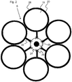
- Fig. 2 are a plurality of pressure vessel 20 via pressure vessel connections 22, which form both inlet and outlet of the respective pressure vessel 20 in the illustrated embodiment, connected to the centrally located sump 24 and together form the pressure storage system 30.
- the pressure vessel connections 22, each with a shut-off valve 26 are closed, so that individual pressure vessel 20, for example, for maintenance purposes, can be separated and brought to the surface.
- the sump 24 is arranged directly on the pump turbine unit 60.
- water is pumped out of the inner cavities 18 of the pressure vessels 20 into the surrounding sea 1 by means of a pump 16 (not shown) arranged in the pump turbine unit 60.
- the pump 16 sucks the water from the pump sump 24 and pumps the water through a water outlet 35 (not shown) directly into the surrounding sea 1.
- the inner cavities 18 of the artificial pressure vessel 20, in the example shown six inner cavities 18 of six pressure vessels 20th form one of the two reservoirs of the pumped storage power plant (the one with the lower potential energy).
- the fact that the pump 16 has to pump the water against the hydrostatic pressure PT prevailing in the water depth T causes a large amount of electrical energy consumed and converted into potential energy, as illustrated by the following examples.
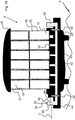
- Fig. 3 shows the embodiment of the Fig. 2 in a side view, wherein the cylindrical shape of the pressure vessel 20 and the central arrangement of the pump turbine element 60 is further illustrated.
- the pressure vessels 20 are connected in the embodiment shown by means of pressure vessel connections 22 to the central pump turbine element 60.
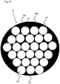
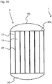
- Fig. 4 shows an alternative embodiment of the accumulator system with an integrated accumulator complex 20a.
- a plurality of internal pressure vessel elements 19 form a common accumulator volume 20a and are interconnected at one end of the integrated pressure accumulator complex 20a. In a standing position this end is the bottom of the integrated accumulator complex, which thus already forms the sump 24 of the accumulator complex, at which the water of the pressure vessel elements 19 can flow together.
- the pressure vessel elements 19 are formed from tubes, for example steel tubes or fiber concrete tubes, which are arranged standing next to each other. The wall 28 is then potted around the pipes so that the cavities and the area directed outwards to the sea water 1 are filled.
- the material thickness of the tubes is either chosen so that this is sufficient, the pressure of the outside To withstand water column, so that the wall 28 secures the pipes for purposes of statics against falling over and additionally complains the structure for sinking on the seabed 8. Otherwise, the material thickness of the pressure vessel elements 19 may also be selected to be thinner, so that the wall 28 of the integrated pressure accumulator complex 20a at the same time also withstands the pressure of the externally applied water column.
- Fig. 5 shows one to Fig. 4 similar embodiment of the pressure vessel 20 as an integrated pressure accumulator complex 20a, wherein the volume enclosed by the wall 28 is optimally utilized by the selection of various suitable pipe diameters of the individual inner pressure vessel elements 19. Possibly.
- the smaller cavities shown in the exterior of the integrated pressure accumulator complex 20a are also capable of being weighted with a ballast.
- Fig. 6 11 shows a side view of an integrated pressure accumulator complex 20a having a plurality of pressure vessel elements 19 and a wall 28 enclosing the pressure vessel elements 19.
- the integrated pressure accumulator complex 20a has a bottom 24 of the accumulator complex at the bottom and is connected via a pressure vessel connection 22 to a central pump turbine unit 60 (see FIG Fig. 7 ) hydraulically connected.
- the pressure vessel connection 22 is thus also water inlet and outlet of the integrated pressure accumulator complex 20a and may also be connected to further pressure vessels 20 (not shown).
- the integrated pressure accumulator complex 20a no mechanically moving parts or components of the power electronics for power generation or power destruction.
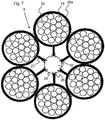
- Fig. 7 shows a schematic plan view of an underwater pumped storage power plant 6 with a central pumping turbine unit 60 and thus connected via pressure vessel connections 22 integral accumulator complexes 20a, each with a plurality of pressure vessel elements 19.
- the integral accumulator complexes 20a in this embodiment have no moving parts, since both the pump 16 as Also, the turbine 36 and shut-off valves 26 are integrated on or in the pump turbine unit 60.
- the shut-off valves 26 can separate the integral accumulator complexes 20a from the central pump turbine unit 60 in the event of an error or in the event of maintenance.
- the pump turbine unit 60 forms at the pump 16 also the hydrostatically lowest point, the sump 24, to which the water flows independently following the gravity.
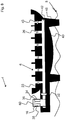
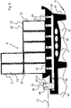
- Fig. 8 shows a further embodiment of the modular pumped storage power plant 6, wherein a bottom body 40 forms the base for receiving other components of the pumped storage power plant 6 and for its attachment or anchoring to the seabed 8.
- the bottom body 40 has in its interior side channels 43 for connecting the pressure accumulator 20 (see FIG. 9 ) with a main channel 42, which in turn is connected in the embodiment shown both with the turbine 16 and with the pump 36.
- the main channel 42 forms both the inlet from the turbine 16 to the pressure accumulators 20 and the flow from the pressure accumulators 20 to the pump 16, so that only one channel and thus possibly only one opening in the conversion of each pressure vessel is needed.
- a shut-off valve 26 is installed in each side channel 43, so that each of the Connection couplings 23 of the side channels 43 mounted pressure vessel 20 can be shut off and separated, for example, for maintenance purposes from the bottom body 40.
- the check valves 26 in the side channels 43 of the bottom body 40 allow to use a universal bottom piece in which, if only a smaller accumulator volume is needed, individual couplings 23 remain unused so that the bottom members are mass produced yet adapted to the particular application can be.
- the bottom body 40 has on its underside feet 46 which stand up for fixing the bottom body 40 on the seabed 8 or are sunk in the seabed 8 when the bottom body 40 rests on the seabed 8.
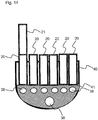
- Fig. 9 1 shows an embodiment of the pumped storage power plant 6 with bottom body 40, pump turbine unit 60, and a plurality of pressure vessels 20 mounted to couplings 23 of the floor body 40 which form a common modular accumulator volume and are supplied by the common pumping turbine unit 60 for filling and removal.
- a plurality of pump turbine units 60 be mounted on a bottom body 40 in order to increase the efficiency and the power output.
- an inlet / outlet valve 32 and the shut-off valves 26 of the side channels 43 are opened and the water flows through a water inlet 34 from the surrounding sea with the hydrostatic pressure PT corresponding to the water depth T.
- the recovered electrical energy is fed through the power line 12 in the general power grid.
- multiple water inlets 34 with valves 32 and turbines 36 may be present.
- the inner cavities 18 may be interspersed with struts or a supporting structure (not shown).
- the cross struts can fulfill a dual function, namely on the one hand to stabilize the pressure vessel 20 and on the other hand to generate turbulence in the flowing through the generator 36 in the inner cavity 18 water to prevent resonant vibrations in the pressure vessel 20.
- the pressure vessel 20 consists of a tubular concrete wall 28 with a connection coupling 23 at the bottom and possibly a further connection coupling 23 at the top, so that the pressure vessel 20 with the bottom body 40 and further pressure vessel 21 to the Pressure vessels 20 can be coupled.
- the wall thickness of the pressure vessel 20 and the bottom body 40 is selected as a function of the water depth T, in which the pumped storage power plant 6 is sunk and depending on the necessary mass so that it can still be sunk.
- the turbines 36 and the pumps 16 are disposed directly on the bottom body 40, for example, directly on the main channel 42 or on a boom 44 of the bottom body 40. In the embodiment shown are pump 16, turbine 36 and water inlet and outlet ports 34, 26 in one Pumpturbinenmaschine 60 integrated.
- the water is passed only over a short distance, namely only through the inlet or outlet opening 34, 26.
- the pumped storage power plant 6 therefore requires only electrical lines 4, 12 from the sea surface to the seabed 8, but not tubes or pipes for the transport of water. Possibly. can even meet an electrical line as power supply and -abtechnisch. It is also advantageous that the pressure difference is not greatly dependent on the level within the pressure vessel 20 due to the large water depth, so that the standing power is independent of the level is substantially constant.
- the bottom body 40 has in its wall 28 cavities 38, which are filled with bulk material, eg sand, to balance the mass of the pumped storage power plant 6.
- the pumped storage power plant 6, or its components bottom body 40 and pressure vessel 20, is preferably initially balanced so that it just floats when it is completely empty, so it can with a ship be transported to the place where it is to be sunk. Subsequently, at the sinking point of the bottom body 40 and / or the pressure vessel 20 with ballast water is weighted so far that the pumped storage power plant 6 sinks.
- the bottom body 40 can be sunk and the pressure vessels 20 are mounted on the bottom 8 to the bottom body 40 or the pressure vessels 20 are already attached to the connection couplings 23 of the bottom body 40 on the water surface and then the entire pumped storage power plant 6 is sunk.
- the amount of water used as ballast water is only the weighting and is not pumped out during normal operation, ie when storing and recovering the electrical energy so that the pumped storage power plant 6 in normal operation always has a greater mass than the displaced water and thus remains on the seabed 8.
- the ballast water can also be filled into the separate cavities 38.
- ballast water can be pumped out, so that the pumped storage power plant 6 reappears or at least so light that, for example, with the rope 52, which is marked at the sea surface with a buoy 54 ( please refer FIG. 1 ), can be caught up.
- the unfinished pressure vessel should be during the production so far protrude from the water that even in a storm, a full running of his inner cavity 18 is not possible.
- the thickness of the wall 28 of the pressure vessel 20 must once withstand the extremely large hydrostatic water pressure and also give the pressure vessel 20 such a high weight that the pumped storage power plant 6 sinks with at least almost empty inner cavity 18 on the seabed 8.
- reinforced concrete can be considered as wall material. The statics is carried out so that the pressure vessel 20 can withstand without damage higher pressures than on the seabed 8 are present.
- valves 26, 32, turbines 36, pumps 16, channels 42, 43 and / or electrical lines, etc. integrated, and the pressure vessel 20 are provided with connection couplings 23 so that they later their Function for many decades.
- the control and control electronics are also located directly on the bottom body 40 and is sunk with.
- Fig. 10 shows a side view of an integrated accumulator complex with several internal pressure vessel elements 19, as with FIGS. 4 and 5 was presented.
- the pressure vessel elements 19 are hydraulically connected to each other via a bottom body 40 and form a common pressure storage volume.
- a lid 46 is attached to the top.
- a pump turbine unit 60 is arranged, so that not separately for each of the pressure vessel elements 19 a pump and / or a turbine is to be used, but in an advantageous manner Way the pressure vessel elements 19 share the common infrastructure to pump (s) 16, turbine (s) 36 and the electrical power supply.
- the integrated accumulator complex with a plurality of pressure vessel elements 19 is thus an independent underwater pumped storage power plant 6.
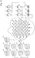
- FIG. 11 is a power grid 48 having a plurality of interconnected consumers 14 and a plurality of interconnected Windkraftanmaschine 2 and photovoltaic systems 3 shown, which form the primary power plants.
- the primary electric power generated by the primary power plants 2, 3 is by means of a plurality of pumped storage power plants 6 according to Fig. 2 to 4 cached.
- the many pumped storage power plants 6 are networked on the seabed 8 only by means of electric underwater lines 50 and provide if necessary, the recovered electrical energy over the existing part of the power supply network 48 to the consumer 14th
- FIGS. 12 to 14 a preferred manufacturing process is presented in which with reference to Fig. 12 First, a raw form of the bottom body 40 is made in a dock or harbor. It is made in such a way that it always floats straight and then towed somewhere in the sea for sinking and is sunk with some ballast on the seabed. If necessary, the dock in the harbor can be used as shuttering of the floor element 40.
- Fig. 13 are in the bottom body 40 already laid connecting pipes to the turbine and the pump, which take over the function of the previously described main channel 42 and the side channels 43 integrally in the bottom body 40.
- a soil weight or a filling compound 41 is filled in the bottom body 40, so poured in, for example, a concrete mass. The filling material can easily envelop the main and side channels 42, 43.
- the bottom body 40 may still be in the harbor or dock used for manufacturing, or may already be on the high seas.
- the pressure vessel 20, 21 are placed in the harbor by container crane on the bottom body 40 and anchored.
- Fig. 15 shows a further embodiment of the underwater pumped storage power plant. It's different from the one with Fig. 9 shown embodiment in that a second pump turbine block 62 is disposed on the bottom body 40, which can increase the power production, for example, in parallel operation and / or increases the reliability.
- the bottom body in this embodiment comprises two inlet / outlet valves, which are located in front of the respective pump turbine block 60, 62.
- the pressure vessels 20 are designed as simple tubes which are connected to each other and at the upper end of a common cover 46 have, for example, also just poured from concrete.
- the pressure vessels 20 are designed as spherical pressure vessels 20 and have simple pressure vessel connections 22.
- the pressure vessels are simply bolted together.
Landscapes
- Engineering & Computer Science (AREA)
- Chemical & Material Sciences (AREA)
- Combustion & Propulsion (AREA)
- Mechanical Engineering (AREA)
- General Engineering & Computer Science (AREA)
- Power Engineering (AREA)
- Life Sciences & Earth Sciences (AREA)
- Sustainable Development (AREA)
- Sustainable Energy (AREA)
- Other Liquid Machine Or Engine Such As Wave Power Use (AREA)
- Wind Motors (AREA)
Applications Claiming Priority (2)
| Application Number | Priority Date | Filing Date | Title |
|---|---|---|---|
| DE102011118206A DE102011118206A1 (de) | 2011-11-11 | 2011-11-11 | Pumpspeicherkraftwerk |
| PCT/EP2012/072357 WO2013068577A1 (de) | 2011-11-11 | 2012-11-12 | Pumpspeicherkraftwerk |
Publications (2)
| Publication Number | Publication Date |
|---|---|
| EP2776705A1 EP2776705A1 (de) | 2014-09-17 |
| EP2776705B1 true EP2776705B1 (de) | 2017-01-04 |
Family
ID=47221359
Family Applications (1)
| Application Number | Title | Priority Date | Filing Date |
|---|---|---|---|
| EP12790493.6A Active EP2776705B1 (de) | 2011-11-11 | 2012-11-12 | Pumpspeicherkraftwerk |
Country Status (5)
| Country | Link |
|---|---|
| US (1) | US9797366B2 (https=) |
| EP (1) | EP2776705B1 (https=) |
| JP (3) | JP5964979B2 (https=) |
| DE (1) | DE102011118206A1 (https=) |
| WO (1) | WO2013068577A1 (https=) |
Families Citing this family (32)
| Publication number | Priority date | Publication date | Assignee | Title |
|---|---|---|---|---|
| DE102013019776B3 (de) * | 2013-11-21 | 2015-01-29 | Gerhard Luther | Tiefschacht-Pumpspeicherkraftwerk (TS.PSKW) |
| DE102013020984A1 (de) * | 2013-12-12 | 2015-06-18 | Heinz Siemast | Stahlhohlkörpersysteme als Pumpspeicherwerk |
| DE102014000811A1 (de) | 2014-01-22 | 2014-05-08 | Rainer L.M. Klopp | Hochleistungs-Pumpspeicherkraftwerk |
| FR3036887B1 (fr) * | 2015-06-01 | 2017-07-14 | Segula Eng & Consulting | Dispositif et procede de conversion d'energie et de stockage d'energie d'origine electrique, sous forme d'air comprime |
| US20160248230A1 (en) * | 2016-04-28 | 2016-08-25 | Solar Turbines Incorporated | Modular power plant assembly |
| US20180100480A1 (en) * | 2016-10-07 | 2018-04-12 | Littoral Power Systems Inc. | Pumped storage hydropower system |
| CN106594926A (zh) * | 2016-11-08 | 2017-04-26 | 广西大学 | 基于排水抗浮基础的地源热泵系统 |
| CA3104836A1 (en) | 2017-03-21 | 2018-09-27 | Strong Force Iot Portfolio 2016, Llc | Systems and methods for shipyard manufactured and ocean delivered nuclear platform |
| GB2566037B (en) | 2017-08-30 | 2020-07-01 | Subsea 7 Norway As | Subsea energy storage |
| DE102018000481A1 (de) * | 2018-01-23 | 2019-07-25 | Bernd Finkbeiner | Micro - pumpspeicherwerk |
| EP3768966B1 (en) | 2018-03-23 | 2022-10-19 | Hans Gude Gudesen | Underwater energy storage system |
| GB2578451A (en) * | 2018-10-26 | 2020-05-13 | Subsea 7 Norway As | Generating electrical power underwater |
| EP3976955B1 (de) | 2019-05-31 | 2023-09-20 | thesum GmbH | Mikro-pumpspeicherkraftwerk |
| DE102019118726B4 (de) | 2019-07-10 | 2021-04-01 | Gerhard Luther | Verfahren zur vorläufigen Nutzung eines zumindest teilweise errichteten unteren Reservoirs für ein Unterwasser-Pumpspeicherkraftwerk |
| DE102019118725A1 (de) * | 2019-07-10 | 2021-01-14 | Gerhard Luther | Verfahren zur Errichtung eines Pumpspeicherkraftwerks in einer Bodenvertiefung, insbesondere in einer Tagebaugrube |
| DE102020002609A1 (de) | 2020-04-30 | 2021-11-04 | Gerhard Luther | Unterwasser-PSKW im Tagebau-Restsee |
| DE102020111844A1 (de) * | 2020-04-30 | 2021-11-04 | Horst Schmidt-Böcking | Modulares Unterwasser-Pumpspeicherkraftwerk-Reservoir |
| JP7484525B2 (ja) * | 2020-07-20 | 2024-05-16 | 株式会社大林組 | 蓄電システム |
| WO2022036000A1 (en) | 2020-08-12 | 2022-02-17 | Riahmedia Inc. Dba Marine Kinetic Energy | Systems and methods for harnessing marine hydrokinetic energy |
| DE102020005091B4 (de) | 2020-08-19 | 2022-07-28 | Michael T. Witt | Hochdruck-Pumpspeicherkaftwerk-System |
| WO2022192386A1 (en) * | 2021-03-09 | 2022-09-15 | American Exchanger Services, Inc. | Energy storage using spherical pressure vessel assembly |
| US12085053B2 (en) | 2021-06-22 | 2024-09-10 | Riahmedia Inc. | Systems and methods for power distribution and harnessing of marine hydrokinetic energy |
| US12234797B2 (en) | 2021-12-03 | 2025-02-25 | Powers8 TECH INC. | Smart controlling systems for energy storage |
| US12180919B2 (en) | 2021-12-03 | 2024-12-31 | Power8 Tech. Inc. | Power tunnel |
| US12355238B2 (en) | 2021-12-03 | 2025-07-08 | Power8 Tech. Inc. | Energy storage systems and methods using heterogeneous pressure media and interactive actuation module |
| KR102794376B1 (ko) | 2021-12-03 | 2025-04-09 | 파워8 테크 인코포레이티드 | 이종 압력 매체 및 양방향 작동 모듈을 사용한 에너지 저장 시스템 및 방법 |
| US12253285B2 (en) | 2021-12-03 | 2025-03-18 | Power8 Tech. Inc. | Geothermal energy storage and conversion systems and methods |
| EP4198297B1 (en) | 2021-12-20 | 2026-03-04 | Sulzer Management AG | Energy storage system |
| CN114530946B (zh) * | 2022-02-10 | 2024-10-18 | 中国电建集团华东勘测设计研究院有限公司 | 一种无缝衔接的交替式液控压缩空气储能系统及方法 |
| US12270369B2 (en) | 2022-05-31 | 2025-04-08 | Sulzer Management Ag | Energy storage system |
| TW202424404A (zh) | 2022-09-13 | 2024-06-16 | 美商能源8科技公司 | 聚光太陽能儲存系統及方法 |
| CN116227238B (zh) * | 2023-05-08 | 2023-07-14 | 国网安徽省电力有限公司经济技术研究院 | 一种抽水蓄能电站运行监测管理系统 |
Family Cites Families (22)
| Publication number | Priority date | Publication date | Assignee | Title |
|---|---|---|---|---|
| US3939356A (en) * | 1974-07-24 | 1976-02-17 | General Public Utilities Corporation | Hydro-air storage electrical generation system |
| US3992881A (en) * | 1975-08-25 | 1976-11-23 | Scherrer William A | Apparatus to generate high pressure air from water |
| GB2032009B (en) * | 1978-10-06 | 1983-03-02 | Grueb R | Apparatus for generating power from hydrostatic pressure |
| DE2843675C3 (de) * | 1978-10-06 | 1982-02-25 | Grüb, Rainer, Ing.(grad.), 7800 Freiburg | Vorrichtung zur Stromerzeugung mittels eines Windrades |
| GB2069618A (en) * | 1980-02-15 | 1981-08-26 | Energy Kinematics Inc | Method of, and apparatus for, utilising the kinetic energy associated with a hydraulic head |
| JPH0715170B2 (ja) * | 1989-04-25 | 1995-02-22 | 鹿島建設株式会社 | 滑動免震式海洋構造物の施工方法 |
| JP3084039B2 (ja) * | 1990-04-12 | 2000-09-04 | 東京電力株式会社 | 発電装置 |
| JP2755778B2 (ja) * | 1990-04-19 | 1998-05-25 | 三菱重工業株式会社 | 深海電力貯蔵プラント |
| JPH04140322A (ja) * | 1990-09-28 | 1992-05-14 | Kajima Corp | 変位抑制装置を有する重力着底式海洋構造物 |
| JPH09317622A (ja) | 1996-05-31 | 1997-12-09 | Mitsubishi Heavy Ind Ltd | 深海電力貯蔵システム |
| JPH1037840A (ja) | 1996-07-22 | 1998-02-13 | Mitsubishi Heavy Ind Ltd | 海中電力貯蔵システム |
| KR20080084797A (ko) * | 2006-01-04 | 2008-09-19 | 다니엘 파르브 | 바다의 파도 에너지를 전력으로 변환 |
| US7281371B1 (en) * | 2006-08-23 | 2007-10-16 | Ebo Group, Inc. | Compressed air pumped hydro energy storage and distribution system |
| US7795748B2 (en) * | 2007-11-30 | 2010-09-14 | Deangeles Steven J | System and process for generating hydroelectric power |
| WO2009111861A1 (en) | 2008-03-13 | 2009-09-17 | Parker V Martin | Submerged generation and storage system (subgenstor) |
| US7911073B2 (en) * | 2008-10-08 | 2011-03-22 | Todd Smith | System and method for a hydro-hydraulic gravitational generator |
| JP2010159695A (ja) | 2009-01-08 | 2010-07-22 | Taiyo Plant Kk | 波エネルギー利用装置および該波エネルギー利用装置を使用した波エネルギー利用プラント |
| BRPI1008151B1 (pt) | 2010-01-05 | 2021-01-12 | Horton Wison Deepwater, Inc. | método para implementar um recipiente de armazenamento de gás abaixo da superfície da água e sistema para armazenar um gás submarino |
| EP2345809A1 (en) * | 2010-01-19 | 2011-07-20 | Janne Aaltonen | Generating hydroenergy |
| US8698338B2 (en) | 2010-03-08 | 2014-04-15 | Massachusetts Institute Of Technology | Offshore energy harvesting, storage, and power generation system |
| US8997475B2 (en) * | 2011-01-10 | 2015-04-07 | General Compression, Inc. | Compressor and expander device with pressure vessel divider baffle and piston |
| DE102011013329A1 (de) | 2011-03-08 | 2012-09-13 | Roentdek-Handels Gmbh | Pumpspeicherkraftwerk |
-
2011
- 2011-11-11 DE DE102011118206A patent/DE102011118206A1/de not_active Ceased
-
2012
- 2012-11-12 WO PCT/EP2012/072357 patent/WO2013068577A1/de not_active Ceased
- 2012-11-12 JP JP2014540499A patent/JP5964979B2/ja active Active
- 2012-11-12 US US14/357,328 patent/US9797366B2/en active Active
- 2012-11-12 EP EP12790493.6A patent/EP2776705B1/de active Active
-
2016
- 2016-06-28 JP JP2016127139A patent/JP2016169742A/ja active Pending
-
2018
- 2018-05-30 JP JP2018102971A patent/JP6781199B2/ja active Active
Also Published As
| Publication number | Publication date |
|---|---|
| JP2016169742A (ja) | 2016-09-23 |
| DE102011118206A1 (de) | 2013-05-16 |
| JP5964979B2 (ja) | 2016-08-03 |
| JP2015504498A (ja) | 2015-02-12 |
| WO2013068577A1 (de) | 2013-05-16 |
| US9797366B2 (en) | 2017-10-24 |
| US20150361948A1 (en) | 2015-12-17 |
| JP2018132068A (ja) | 2018-08-23 |
| EP2776705A1 (de) | 2014-09-17 |
| JP6781199B2 (ja) | 2020-11-04 |
Similar Documents
| Publication | Publication Date | Title |
|---|---|---|
| EP2776705B1 (de) | Pumpspeicherkraftwerk | |
| EP2683933B1 (de) | Pumpspeicherkraftwerk | |
| EP2681445B1 (de) | Hydraulischer energiespeicher | |
| DE112013002285B4 (de) | Off-Shore-Pumpspeicher-Kraftwerk | |
| WO2021005016A1 (de) | Verfahren zur errichtung eines pumpspeicherkraftwerks in einer bodenvertiefung, insbesondere in einer tagebaugrube | |
| EP3683438B1 (de) | Pumpspeicherwerk in einem gewässer und verfahren zum betrieb | |
| CH708605A2 (de) | Pumpwasserdruck-Luftpolster-Energiespeicherung mit einstellbarem über die Druckluft regulierbarem konstantem Wasserdruck für den Turbinenantrieb. | |
| DE102019118726B4 (de) | Verfahren zur vorläufigen Nutzung eines zumindest teilweise errichteten unteren Reservoirs für ein Unterwasser-Pumpspeicherkraftwerk | |
| WO2014072415A1 (de) | Pumpspeicher-wasserkraftwerk und energieerzeugungs- und speichersystem mit einem solchen kraftwerk | |
| DE102012011491A1 (de) | Unterwasser-Druckluft-Energiespeicher mit volumenvariablem Druckspeichergefäß | |
| DE102014000811A1 (de) | Hochleistungs-Pumpspeicherkraftwerk | |
| EP2725143B1 (de) | Pumpspeicherwerk zur Energiespeicherung | |
| DE102006059233A1 (de) | Verfahren zur wechselweisen Ein- und Ausspeicherung von Energie sowie Speichervorrichtung hierfür | |
| EP1890032A2 (de) | Schwimmender Wellenenergiekonverter mit Verfahren zur Positionierung | |
| DE102021004099A1 (de) | Pumpspeicherkraftwerk mit einem von einer Ringstaumauer umschlossenen Speicherbecken | |
| DE102020002609A9 (de) | Unterwasser-PSKW im Tagebau-Restsee | |
| DE102008009453A1 (de) | Wasserkraftwerk, mehrstufig, unter Nutzung von Ebbe und Flut, Verfahren und Technik | |
| DE102013020984A1 (de) | Stahlhohlkörpersysteme als Pumpspeicherwerk | |
| AT523139A1 (de) | Verfahren zur Energiegewinnung und Speicherung | |
| WO2012167783A2 (de) | Tankspeicherkraftwerk und verfahren zur herstellung eines tankspeicherkraftwerks | |
| DE102019003203B4 (de) | Pumpspeicherwerk | |
| WO2023174549A1 (de) | Pumpspeicherkraftwerk | |
| DE102004052183A1 (de) | Schwimmeinheit zur elektrischen Stromerzeugung | |
| DE102021100873A1 (de) | Hydromechanische Energiespeicher- und Energieumwandlungsvorrichtung | |
| DE2931176A1 (de) | Verfahren zur erzeugung von elektrischem strom auch unterhalb des meeresspiegels und vorrichtung zur durchfuehrung des verfahrens. |
Legal Events
| Date | Code | Title | Description |
|---|---|---|---|
| PUAI | Public reference made under article 153(3) epc to a published international application that has entered the european phase |
Free format text: ORIGINAL CODE: 0009012 |
|
| 17P | Request for examination filed |
Effective date: 20140411 |
|
| AK | Designated contracting states |
Kind code of ref document: A1 Designated state(s): AL AT BE BG CH CY CZ DE DK EE ES FI FR GB GR HR HU IE IS IT LI LT LU LV MC MK MT NL NO PL PT RO RS SE SI SK SM TR |
|
| DAX | Request for extension of the european patent (deleted) | ||
| 17Q | First examination report despatched |
Effective date: 20150414 |
|
| GRAP | Despatch of communication of intention to grant a patent |
Free format text: ORIGINAL CODE: EPIDOSNIGR1 |
|
| RIC1 | Information provided on ipc code assigned before grant |
Ipc: F03B 13/06 20060101ALI20160614BHEP Ipc: F03D 9/14 20160101ALI20160614BHEP Ipc: F03B 3/10 20060101AFI20160614BHEP Ipc: F03D 9/10 20160101ALI20160614BHEP |
|
| INTG | Intention to grant announced |
Effective date: 20160713 |
|
| GRAS | Grant fee paid |
Free format text: ORIGINAL CODE: EPIDOSNIGR3 |
|
| GRAA | (expected) grant |
Free format text: ORIGINAL CODE: 0009210 |
|
| AK | Designated contracting states |
Kind code of ref document: B1 Designated state(s): AL AT BE BG CH CY CZ DE DK EE ES FI FR GB GR HR HU IE IS IT LI LT LU LV MC MK MT NL NO PL PT RO RS SE SI SK SM TR |
|
| REG | Reference to a national code |
Ref country code: GB Ref legal event code: FG4D Free format text: NOT ENGLISH |
|
| REG | Reference to a national code |
Ref country code: CH Ref legal event code: EP |
|
| REG | Reference to a national code |
Ref country code: AT Ref legal event code: REF Ref document number: 859494 Country of ref document: AT Kind code of ref document: T Effective date: 20170115 |
|
| REG | Reference to a national code |
Ref country code: IE Ref legal event code: FG4D Free format text: LANGUAGE OF EP DOCUMENT: GERMAN |
|
| REG | Reference to a national code |
Ref country code: DE Ref legal event code: R096 Ref document number: 502012009238 Country of ref document: DE |
|
| REG | Reference to a national code |
Ref country code: LT Ref legal event code: MG4D Ref country code: NL Ref legal event code: MP Effective date: 20170104 |
|
| REG | Reference to a national code |
Ref country code: NO Ref legal event code: T2 Effective date: 20170104 |
|
| PG25 | Lapsed in a contracting state [announced via postgrant information from national office to epo] |
Ref country code: NL Free format text: LAPSE BECAUSE OF FAILURE TO SUBMIT A TRANSLATION OF THE DESCRIPTION OR TO PAY THE FEE WITHIN THE PRESCRIBED TIME-LIMIT Effective date: 20170104 |
|
| PG25 | Lapsed in a contracting state [announced via postgrant information from national office to epo] |
Ref country code: LT Free format text: LAPSE BECAUSE OF FAILURE TO SUBMIT A TRANSLATION OF THE DESCRIPTION OR TO PAY THE FEE WITHIN THE PRESCRIBED TIME-LIMIT Effective date: 20170104 Ref country code: FI Free format text: LAPSE BECAUSE OF FAILURE TO SUBMIT A TRANSLATION OF THE DESCRIPTION OR TO PAY THE FEE WITHIN THE PRESCRIBED TIME-LIMIT Effective date: 20170104 Ref country code: GR Free format text: LAPSE BECAUSE OF FAILURE TO SUBMIT A TRANSLATION OF THE DESCRIPTION OR TO PAY THE FEE WITHIN THE PRESCRIBED TIME-LIMIT Effective date: 20170405 Ref country code: HR Free format text: LAPSE BECAUSE OF FAILURE TO SUBMIT A TRANSLATION OF THE DESCRIPTION OR TO PAY THE FEE WITHIN THE PRESCRIBED TIME-LIMIT Effective date: 20170104 Ref country code: IS Free format text: LAPSE BECAUSE OF FAILURE TO SUBMIT A TRANSLATION OF THE DESCRIPTION OR TO PAY THE FEE WITHIN THE PRESCRIBED TIME-LIMIT Effective date: 20170504 |
|
| PG25 | Lapsed in a contracting state [announced via postgrant information from national office to epo] |
Ref country code: PT Free format text: LAPSE BECAUSE OF FAILURE TO SUBMIT A TRANSLATION OF THE DESCRIPTION OR TO PAY THE FEE WITHIN THE PRESCRIBED TIME-LIMIT Effective date: 20170504 Ref country code: LV Free format text: LAPSE BECAUSE OF FAILURE TO SUBMIT A TRANSLATION OF THE DESCRIPTION OR TO PAY THE FEE WITHIN THE PRESCRIBED TIME-LIMIT Effective date: 20170104 Ref country code: ES Free format text: LAPSE BECAUSE OF FAILURE TO SUBMIT A TRANSLATION OF THE DESCRIPTION OR TO PAY THE FEE WITHIN THE PRESCRIBED TIME-LIMIT Effective date: 20170104 Ref country code: PL Free format text: LAPSE BECAUSE OF FAILURE TO SUBMIT A TRANSLATION OF THE DESCRIPTION OR TO PAY THE FEE WITHIN THE PRESCRIBED TIME-LIMIT Effective date: 20170104 Ref country code: SE Free format text: LAPSE BECAUSE OF FAILURE TO SUBMIT A TRANSLATION OF THE DESCRIPTION OR TO PAY THE FEE WITHIN THE PRESCRIBED TIME-LIMIT Effective date: 20170104 Ref country code: RS Free format text: LAPSE BECAUSE OF FAILURE TO SUBMIT A TRANSLATION OF THE DESCRIPTION OR TO PAY THE FEE WITHIN THE PRESCRIBED TIME-LIMIT Effective date: 20170104 Ref country code: BG Free format text: LAPSE BECAUSE OF FAILURE TO SUBMIT A TRANSLATION OF THE DESCRIPTION OR TO PAY THE FEE WITHIN THE PRESCRIBED TIME-LIMIT Effective date: 20170404 |
|
| REG | Reference to a national code |
Ref country code: DE Ref legal event code: R097 Ref document number: 502012009238 Country of ref document: DE |
|
| PG25 | Lapsed in a contracting state [announced via postgrant information from national office to epo] |
Ref country code: RO Free format text: LAPSE BECAUSE OF FAILURE TO SUBMIT A TRANSLATION OF THE DESCRIPTION OR TO PAY THE FEE WITHIN THE PRESCRIBED TIME-LIMIT Effective date: 20170104 Ref country code: SK Free format text: LAPSE BECAUSE OF FAILURE TO SUBMIT A TRANSLATION OF THE DESCRIPTION OR TO PAY THE FEE WITHIN THE PRESCRIBED TIME-LIMIT Effective date: 20170104 Ref country code: CZ Free format text: LAPSE BECAUSE OF FAILURE TO SUBMIT A TRANSLATION OF THE DESCRIPTION OR TO PAY THE FEE WITHIN THE PRESCRIBED TIME-LIMIT Effective date: 20170104 Ref country code: EE Free format text: LAPSE BECAUSE OF FAILURE TO SUBMIT A TRANSLATION OF THE DESCRIPTION OR TO PAY THE FEE WITHIN THE PRESCRIBED TIME-LIMIT Effective date: 20170104 Ref country code: IT Free format text: LAPSE BECAUSE OF FAILURE TO SUBMIT A TRANSLATION OF THE DESCRIPTION OR TO PAY THE FEE WITHIN THE PRESCRIBED TIME-LIMIT Effective date: 20170104 |
|
| PLBE | No opposition filed within time limit |
Free format text: ORIGINAL CODE: 0009261 |
|
| STAA | Information on the status of an ep patent application or granted ep patent |
Free format text: STATUS: NO OPPOSITION FILED WITHIN TIME LIMIT |
|
| REG | Reference to a national code |
Ref country code: FR Ref legal event code: PLFP Year of fee payment: 6 |
|
| PG25 | Lapsed in a contracting state [announced via postgrant information from national office to epo] |
Ref country code: DK Free format text: LAPSE BECAUSE OF FAILURE TO SUBMIT A TRANSLATION OF THE DESCRIPTION OR TO PAY THE FEE WITHIN THE PRESCRIBED TIME-LIMIT Effective date: 20170104 Ref country code: SM Free format text: LAPSE BECAUSE OF FAILURE TO SUBMIT A TRANSLATION OF THE DESCRIPTION OR TO PAY THE FEE WITHIN THE PRESCRIBED TIME-LIMIT Effective date: 20170104 |
|
| 26N | No opposition filed |
Effective date: 20171005 |
|
| PG25 | Lapsed in a contracting state [announced via postgrant information from national office to epo] |
Ref country code: SI Free format text: LAPSE BECAUSE OF FAILURE TO SUBMIT A TRANSLATION OF THE DESCRIPTION OR TO PAY THE FEE WITHIN THE PRESCRIBED TIME-LIMIT Effective date: 20170104 |
|
| PG25 | Lapsed in a contracting state [announced via postgrant information from national office to epo] |
Ref country code: MC Free format text: LAPSE BECAUSE OF FAILURE TO SUBMIT A TRANSLATION OF THE DESCRIPTION OR TO PAY THE FEE WITHIN THE PRESCRIBED TIME-LIMIT Effective date: 20170104 |
|
| PG25 | Lapsed in a contracting state [announced via postgrant information from national office to epo] |
Ref country code: LI Free format text: LAPSE BECAUSE OF NON-PAYMENT OF DUE FEES Effective date: 20171130 Ref country code: CH Free format text: LAPSE BECAUSE OF NON-PAYMENT OF DUE FEES Effective date: 20171130 |
|
| PG25 | Lapsed in a contracting state [announced via postgrant information from national office to epo] |
Ref country code: LU Free format text: LAPSE BECAUSE OF NON-PAYMENT OF DUE FEES Effective date: 20171112 |
|
| PG25 | Lapsed in a contracting state [announced via postgrant information from national office to epo] |
Ref country code: MT Free format text: LAPSE BECAUSE OF FAILURE TO SUBMIT A TRANSLATION OF THE DESCRIPTION OR TO PAY THE FEE WITHIN THE PRESCRIBED TIME-LIMIT Effective date: 20170104 |
|
| REG | Reference to a national code |
Ref country code: AT Ref legal event code: MM01 Ref document number: 859494 Country of ref document: AT Kind code of ref document: T Effective date: 20171112 |
|
| PG25 | Lapsed in a contracting state [announced via postgrant information from national office to epo] |
Ref country code: AT Free format text: LAPSE BECAUSE OF NON-PAYMENT OF DUE FEES Effective date: 20171112 |
|
| PG25 | Lapsed in a contracting state [announced via postgrant information from national office to epo] |
Ref country code: HU Free format text: LAPSE BECAUSE OF FAILURE TO SUBMIT A TRANSLATION OF THE DESCRIPTION OR TO PAY THE FEE WITHIN THE PRESCRIBED TIME-LIMIT; INVALID AB INITIO Effective date: 20121112 |
|
| PG25 | Lapsed in a contracting state [announced via postgrant information from national office to epo] |
Ref country code: CY Free format text: LAPSE BECAUSE OF NON-PAYMENT OF DUE FEES Effective date: 20170104 |
|
| PG25 | Lapsed in a contracting state [announced via postgrant information from national office to epo] |
Ref country code: MK Free format text: LAPSE BECAUSE OF FAILURE TO SUBMIT A TRANSLATION OF THE DESCRIPTION OR TO PAY THE FEE WITHIN THE PRESCRIBED TIME-LIMIT Effective date: 20170104 |
|
| PG25 | Lapsed in a contracting state [announced via postgrant information from national office to epo] |
Ref country code: TR Free format text: LAPSE BECAUSE OF FAILURE TO SUBMIT A TRANSLATION OF THE DESCRIPTION OR TO PAY THE FEE WITHIN THE PRESCRIBED TIME-LIMIT Effective date: 20170104 |
|
| PG25 | Lapsed in a contracting state [announced via postgrant information from national office to epo] |
Ref country code: AL Free format text: LAPSE BECAUSE OF FAILURE TO SUBMIT A TRANSLATION OF THE DESCRIPTION OR TO PAY THE FEE WITHIN THE PRESCRIBED TIME-LIMIT Effective date: 20170104 |
|
| REG | Reference to a national code |
Ref country code: DE Ref legal event code: R084 Ref document number: 502012009238 Country of ref document: DE |
|
| REG | Reference to a national code |
Ref country code: GB Ref legal event code: 746 Effective date: 20211229 |
|
| P01 | Opt-out of the competence of the unified patent court (upc) registered |
Effective date: 20230426 |
|
| PGFP | Annual fee paid to national office [announced via postgrant information from national office to epo] |
Ref country code: DE Payment date: 20251125 Year of fee payment: 14 |
|
| PGFP | Annual fee paid to national office [announced via postgrant information from national office to epo] |
Ref country code: GB Payment date: 20251120 Year of fee payment: 14 |
|
| PGFP | Annual fee paid to national office [announced via postgrant information from national office to epo] |
Ref country code: NO Payment date: 20251118 Year of fee payment: 14 |
|
| PGFP | Annual fee paid to national office [announced via postgrant information from national office to epo] |
Ref country code: FR Payment date: 20251120 Year of fee payment: 14 |
|
| PGFP | Annual fee paid to national office [announced via postgrant information from national office to epo] |
Ref country code: BE Payment date: 20251118 Year of fee payment: 14 |
|
| PGFP | Annual fee paid to national office [announced via postgrant information from national office to epo] |
Ref country code: IE Payment date: 20251120 Year of fee payment: 14 |