EP2776705B1 - Pumped-storage power plant - Google Patents
Pumped-storage power plant Download PDFInfo
- Publication number
- EP2776705B1 EP2776705B1 EP12790493.6A EP12790493A EP2776705B1 EP 2776705 B1 EP2776705 B1 EP 2776705B1 EP 12790493 A EP12790493 A EP 12790493A EP 2776705 B1 EP2776705 B1 EP 2776705B1
- Authority
- EP
- European Patent Office
- Prior art keywords
- water
- power plant
- pressure
- storage power
- pumped storage
- Prior art date
- Legal status (The legal status is an assumption and is not a legal conclusion. Google has not performed a legal analysis and makes no representation as to the accuracy of the status listed.)
- Active
Links
- 238000003860 storage Methods 0.000 title claims description 157
- XLYOFNOQVPJJNP-UHFFFAOYSA-N water Substances O XLYOFNOQVPJJNP-UHFFFAOYSA-N 0.000 claims description 196
- 238000005381 potential energy Methods 0.000 claims description 19
- 230000002706 hydrostatic effect Effects 0.000 claims description 17
- 230000008878 coupling Effects 0.000 claims description 15
- 238000010168 coupling process Methods 0.000 claims description 15
- 238000005859 coupling reaction Methods 0.000 claims description 15
- 238000005086 pumping Methods 0.000 claims description 13
- 238000012423 maintenance Methods 0.000 claims description 10
- 239000013590 bulk material Substances 0.000 claims description 9
- 238000013461 design Methods 0.000 claims description 9
- 239000000463 material Substances 0.000 claims description 9
- 238000009434 installation Methods 0.000 claims description 7
- 238000000034 method Methods 0.000 claims description 7
- 230000002441 reversible effect Effects 0.000 claims description 7
- 238000004519 manufacturing process Methods 0.000 claims description 6
- 238000007667 floating Methods 0.000 claims description 5
- 238000007789 sealing Methods 0.000 claims description 5
- 238000004140 cleaning Methods 0.000 claims description 4
- 238000010616 electrical installation Methods 0.000 claims description 2
- 239000000945 filler Substances 0.000 claims 3
- 230000002787 reinforcement Effects 0.000 claims 1
- 239000004567 concrete Substances 0.000 description 9
- 238000004146 energy storage Methods 0.000 description 9
- 238000010248 power generation Methods 0.000 description 6
- 230000005611 electricity Effects 0.000 description 5
- 230000006870 function Effects 0.000 description 5
- 239000002689 soil Substances 0.000 description 5
- 229910000831 Steel Inorganic materials 0.000 description 4
- 238000010276 construction Methods 0.000 description 4
- 239000000835 fiber Substances 0.000 description 4
- 239000013535 sea water Substances 0.000 description 4
- 239000010959 steel Substances 0.000 description 4
- 238000004873 anchoring Methods 0.000 description 3
- 150000001875 compounds Chemical class 0.000 description 3
- 230000006378 damage Effects 0.000 description 3
- 230000005484 gravity Effects 0.000 description 3
- OMBVEVHRIQULKW-DNQXCXABSA-M (3r,5r)-7-[3-(4-fluorophenyl)-8-oxo-7-phenyl-1-propan-2-yl-5,6-dihydro-4h-pyrrolo[2,3-c]azepin-2-yl]-3,5-dihydroxyheptanoate Chemical compound O=C1C=2N(C(C)C)C(CC[C@@H](O)C[C@@H](O)CC([O-])=O)=C(C=3C=CC(F)=CC=3)C=2CCCN1C1=CC=CC=C1 OMBVEVHRIQULKW-DNQXCXABSA-M 0.000 description 2
- 101100313164 Caenorhabditis elegans sea-1 gene Proteins 0.000 description 2
- 230000008901 benefit Effects 0.000 description 2
- 238000004364 calculation method Methods 0.000 description 2
- 229940126540 compound 41 Drugs 0.000 description 2
- 238000011161 development Methods 0.000 description 2
- 230000018109 developmental process Effects 0.000 description 2
- 238000006073 displacement reaction Methods 0.000 description 2
- 238000009826 distribution Methods 0.000 description 2
- 230000006855 networking Effects 0.000 description 2
- 230000000149 penetrating effect Effects 0.000 description 2
- 230000008569 process Effects 0.000 description 2
- 238000011084 recovery Methods 0.000 description 2
- 230000009467 reduction Effects 0.000 description 2
- 230000001172 regenerating effect Effects 0.000 description 2
- 239000011150 reinforced concrete Substances 0.000 description 2
- 239000004576 sand Substances 0.000 description 2
- 230000003068 static effect Effects 0.000 description 2
- UDQTXCHQKHIQMH-KYGLGHNPSA-N (3ar,5s,6s,7r,7ar)-5-(difluoromethyl)-2-(ethylamino)-5,6,7,7a-tetrahydro-3ah-pyrano[3,2-d][1,3]thiazole-6,7-diol Chemical compound S1C(NCC)=N[C@H]2[C@@H]1O[C@H](C(F)F)[C@@H](O)[C@@H]2O UDQTXCHQKHIQMH-KYGLGHNPSA-N 0.000 description 1
- 101100420946 Caenorhabditis elegans sea-2 gene Proteins 0.000 description 1
- 208000026139 Memory disease Diseases 0.000 description 1
- 241000826860 Trapezium Species 0.000 description 1
- 238000009825 accumulation Methods 0.000 description 1
- 238000005273 aeration Methods 0.000 description 1
- 238000013459 approach Methods 0.000 description 1
- 238000009750 centrifugal casting Methods 0.000 description 1
- 238000006243 chemical reaction Methods 0.000 description 1
- 239000002131 composite material Substances 0.000 description 1
- 229940125936 compound 42 Drugs 0.000 description 1
- 230000007423 decrease Effects 0.000 description 1
- 230000001419 dependent effect Effects 0.000 description 1
- 238000007599 discharging Methods 0.000 description 1
- 230000009977 dual effect Effects 0.000 description 1
- 238000005868 electrolysis reaction Methods 0.000 description 1
- VJJPUSNTGOMMGY-MRVIYFEKSA-N etoposide Chemical compound COC1=C(O)C(OC)=CC([C@@H]2C3=CC=4OCOC=4C=C3[C@@H](O[C@H]3[C@@H]([C@@H](O)[C@@H]4O[C@H](C)OC[C@H]4O3)O)[C@@H]3[C@@H]2C(OC3)=O)=C1 VJJPUSNTGOMMGY-MRVIYFEKSA-N 0.000 description 1
- 239000011210 fiber-reinforced concrete Substances 0.000 description 1
- 238000003306 harvesting Methods 0.000 description 1
- 230000010354 integration Effects 0.000 description 1
- 230000006984 memory degeneration Effects 0.000 description 1
- 238000005065 mining Methods 0.000 description 1
- 239000000203 mixture Substances 0.000 description 1
- 230000005855 radiation Effects 0.000 description 1
- 230000008439 repair process Effects 0.000 description 1
- 239000013049 sediment Substances 0.000 description 1
- 238000009416 shuttering Methods 0.000 description 1
- 239000000126 substance Substances 0.000 description 1
- 238000011144 upstream manufacturing Methods 0.000 description 1
Images


Classifications
-
- F—MECHANICAL ENGINEERING; LIGHTING; HEATING; WEAPONS; BLASTING
- F03—MACHINES OR ENGINES FOR LIQUIDS; WIND, SPRING, OR WEIGHT MOTORS; PRODUCING MECHANICAL POWER OR A REACTIVE PROPULSIVE THRUST, NOT OTHERWISE PROVIDED FOR
- F03B—MACHINES OR ENGINES FOR LIQUIDS
- F03B13/00—Adaptations of machines or engines for special use; Combinations of machines or engines with driving or driven apparatus; Power stations or aggregates
- F03B13/10—Submerged units incorporating electric generators or motors
-
- F—MECHANICAL ENGINEERING; LIGHTING; HEATING; WEAPONS; BLASTING
- F03—MACHINES OR ENGINES FOR LIQUIDS; WIND, SPRING, OR WEIGHT MOTORS; PRODUCING MECHANICAL POWER OR A REACTIVE PROPULSIVE THRUST, NOT OTHERWISE PROVIDED FOR
- F03B—MACHINES OR ENGINES FOR LIQUIDS
- F03B13/00—Adaptations of machines or engines for special use; Combinations of machines or engines with driving or driven apparatus; Power stations or aggregates
- F03B13/06—Stations or aggregates of water-storage type, e.g. comprising a turbine and a pump
-
- F—MECHANICAL ENGINEERING; LIGHTING; HEATING; WEAPONS; BLASTING
- F03—MACHINES OR ENGINES FOR LIQUIDS; WIND, SPRING, OR WEIGHT MOTORS; PRODUCING MECHANICAL POWER OR A REACTIVE PROPULSIVE THRUST, NOT OTHERWISE PROVIDED FOR
- F03B—MACHINES OR ENGINES FOR LIQUIDS
- F03B3/00—Machines or engines of reaction type; Parts or details peculiar thereto
- F03B3/10—Machines or engines of reaction type; Parts or details peculiar thereto characterised by having means for functioning alternatively as pumps or turbines
-
- F—MECHANICAL ENGINEERING; LIGHTING; HEATING; WEAPONS; BLASTING
- F03—MACHINES OR ENGINES FOR LIQUIDS; WIND, SPRING, OR WEIGHT MOTORS; PRODUCING MECHANICAL POWER OR A REACTIVE PROPULSIVE THRUST, NOT OTHERWISE PROVIDED FOR
- F03D—WIND MOTORS
- F03D9/00—Adaptations of wind motors for special use; Combinations of wind motors with apparatus driven thereby; Wind motors specially adapted for installation in particular locations
- F03D9/10—Combinations of wind motors with apparatus storing energy
- F03D9/13—Combinations of wind motors with apparatus storing energy storing gravitational potential energy
- F03D9/14—Combinations of wind motors with apparatus storing energy storing gravitational potential energy using liquids
-
- F—MECHANICAL ENGINEERING; LIGHTING; HEATING; WEAPONS; BLASTING
- F03—MACHINES OR ENGINES FOR LIQUIDS; WIND, SPRING, OR WEIGHT MOTORS; PRODUCING MECHANICAL POWER OR A REACTIVE PROPULSIVE THRUST, NOT OTHERWISE PROVIDED FOR
- F03D—WIND MOTORS
- F03D9/00—Adaptations of wind motors for special use; Combinations of wind motors with apparatus driven thereby; Wind motors specially adapted for installation in particular locations
- F03D9/20—Wind motors characterised by the driven apparatus
- F03D9/25—Wind motors characterised by the driven apparatus the apparatus being an electrical generator
-
- F—MECHANICAL ENGINEERING; LIGHTING; HEATING; WEAPONS; BLASTING
- F03—MACHINES OR ENGINES FOR LIQUIDS; WIND, SPRING, OR WEIGHT MOTORS; PRODUCING MECHANICAL POWER OR A REACTIVE PROPULSIVE THRUST, NOT OTHERWISE PROVIDED FOR
- F03D—WIND MOTORS
- F03D9/00—Adaptations of wind motors for special use; Combinations of wind motors with apparatus driven thereby; Wind motors specially adapted for installation in particular locations
- F03D9/007—Adaptations of wind motors for special use; Combinations of wind motors with apparatus driven thereby; Wind motors specially adapted for installation in particular locations the wind motor being combined with means for converting solar radiation into useful energy
-
- H—ELECTRICITY
- H02—GENERATION; CONVERSION OR DISTRIBUTION OF ELECTRIC POWER
- H02S—GENERATION OF ELECTRIC POWER BY CONVERSION OF INFRARED RADIATION, VISIBLE LIGHT OR ULTRAVIOLET LIGHT, e.g. USING PHOTOVOLTAIC [PV] MODULES
- H02S10/00—PV power plants; Combinations of PV energy systems with other systems for the generation of electric power
- H02S10/10—PV power plants; Combinations of PV energy systems with other systems for the generation of electric power including a supplementary source of electric power, e.g. hybrid diesel-PV energy systems
- H02S10/12—Hybrid wind-PV energy systems
-
- Y—GENERAL TAGGING OF NEW TECHNOLOGICAL DEVELOPMENTS; GENERAL TAGGING OF CROSS-SECTIONAL TECHNOLOGIES SPANNING OVER SEVERAL SECTIONS OF THE IPC; TECHNICAL SUBJECTS COVERED BY FORMER USPC CROSS-REFERENCE ART COLLECTIONS [XRACs] AND DIGESTS
- Y02—TECHNOLOGIES OR APPLICATIONS FOR MITIGATION OR ADAPTATION AGAINST CLIMATE CHANGE
- Y02E—REDUCTION OF GREENHOUSE GAS [GHG] EMISSIONS, RELATED TO ENERGY GENERATION, TRANSMISSION OR DISTRIBUTION
- Y02E10/00—Energy generation through renewable energy sources
- Y02E10/20—Hydro energy
-
- Y—GENERAL TAGGING OF NEW TECHNOLOGICAL DEVELOPMENTS; GENERAL TAGGING OF CROSS-SECTIONAL TECHNOLOGIES SPANNING OVER SEVERAL SECTIONS OF THE IPC; TECHNICAL SUBJECTS COVERED BY FORMER USPC CROSS-REFERENCE ART COLLECTIONS [XRACs] AND DIGESTS
- Y02—TECHNOLOGIES OR APPLICATIONS FOR MITIGATION OR ADAPTATION AGAINST CLIMATE CHANGE
- Y02E—REDUCTION OF GREENHOUSE GAS [GHG] EMISSIONS, RELATED TO ENERGY GENERATION, TRANSMISSION OR DISTRIBUTION
- Y02E10/00—Energy generation through renewable energy sources
- Y02E10/30—Energy from the sea, e.g. using wave energy or salinity gradient
-
- Y—GENERAL TAGGING OF NEW TECHNOLOGICAL DEVELOPMENTS; GENERAL TAGGING OF CROSS-SECTIONAL TECHNOLOGIES SPANNING OVER SEVERAL SECTIONS OF THE IPC; TECHNICAL SUBJECTS COVERED BY FORMER USPC CROSS-REFERENCE ART COLLECTIONS [XRACs] AND DIGESTS
- Y02—TECHNOLOGIES OR APPLICATIONS FOR MITIGATION OR ADAPTATION AGAINST CLIMATE CHANGE
- Y02E—REDUCTION OF GREENHOUSE GAS [GHG] EMISSIONS, RELATED TO ENERGY GENERATION, TRANSMISSION OR DISTRIBUTION
- Y02E10/00—Energy generation through renewable energy sources
- Y02E10/50—Photovoltaic [PV] energy
-
- Y—GENERAL TAGGING OF NEW TECHNOLOGICAL DEVELOPMENTS; GENERAL TAGGING OF CROSS-SECTIONAL TECHNOLOGIES SPANNING OVER SEVERAL SECTIONS OF THE IPC; TECHNICAL SUBJECTS COVERED BY FORMER USPC CROSS-REFERENCE ART COLLECTIONS [XRACs] AND DIGESTS
- Y02—TECHNOLOGIES OR APPLICATIONS FOR MITIGATION OR ADAPTATION AGAINST CLIMATE CHANGE
- Y02E—REDUCTION OF GREENHOUSE GAS [GHG] EMISSIONS, RELATED TO ENERGY GENERATION, TRANSMISSION OR DISTRIBUTION
- Y02E10/00—Energy generation through renewable energy sources
- Y02E10/70—Wind energy
- Y02E10/72—Wind turbines with rotation axis in wind direction
-
- Y—GENERAL TAGGING OF NEW TECHNOLOGICAL DEVELOPMENTS; GENERAL TAGGING OF CROSS-SECTIONAL TECHNOLOGIES SPANNING OVER SEVERAL SECTIONS OF THE IPC; TECHNICAL SUBJECTS COVERED BY FORMER USPC CROSS-REFERENCE ART COLLECTIONS [XRACs] AND DIGESTS
- Y02—TECHNOLOGIES OR APPLICATIONS FOR MITIGATION OR ADAPTATION AGAINST CLIMATE CHANGE
- Y02E—REDUCTION OF GREENHOUSE GAS [GHG] EMISSIONS, RELATED TO ENERGY GENERATION, TRANSMISSION OR DISTRIBUTION
- Y02E60/00—Enabling technologies; Technologies with a potential or indirect contribution to GHG emissions mitigation
- Y02E60/16—Mechanical energy storage, e.g. flywheels or pressurised fluids
-
- Y—GENERAL TAGGING OF NEW TECHNOLOGICAL DEVELOPMENTS; GENERAL TAGGING OF CROSS-SECTIONAL TECHNOLOGIES SPANNING OVER SEVERAL SECTIONS OF THE IPC; TECHNICAL SUBJECTS COVERED BY FORMER USPC CROSS-REFERENCE ART COLLECTIONS [XRACs] AND DIGESTS
- Y02—TECHNOLOGIES OR APPLICATIONS FOR MITIGATION OR ADAPTATION AGAINST CLIMATE CHANGE
- Y02E—REDUCTION OF GREENHOUSE GAS [GHG] EMISSIONS, RELATED TO ENERGY GENERATION, TRANSMISSION OR DISTRIBUTION
- Y02E70/00—Other energy conversion or management systems reducing GHG emissions
- Y02E70/30—Systems combining energy storage with energy generation of non-fossil origin
-
- Y—GENERAL TAGGING OF NEW TECHNOLOGICAL DEVELOPMENTS; GENERAL TAGGING OF CROSS-SECTIONAL TECHNOLOGIES SPANNING OVER SEVERAL SECTIONS OF THE IPC; TECHNICAL SUBJECTS COVERED BY FORMER USPC CROSS-REFERENCE ART COLLECTIONS [XRACs] AND DIGESTS
- Y02—TECHNOLOGIES OR APPLICATIONS FOR MITIGATION OR ADAPTATION AGAINST CLIMATE CHANGE
- Y02P—CLIMATE CHANGE MITIGATION TECHNOLOGIES IN THE PRODUCTION OR PROCESSING OF GOODS
- Y02P70/00—Climate change mitigation technologies in the production process for final industrial or consumer products
- Y02P70/50—Manufacturing or production processes characterised by the final manufactured product
-
- Y—GENERAL TAGGING OF NEW TECHNOLOGICAL DEVELOPMENTS; GENERAL TAGGING OF CROSS-SECTIONAL TECHNOLOGIES SPANNING OVER SEVERAL SECTIONS OF THE IPC; TECHNICAL SUBJECTS COVERED BY FORMER USPC CROSS-REFERENCE ART COLLECTIONS [XRACs] AND DIGESTS
- Y02—TECHNOLOGIES OR APPLICATIONS FOR MITIGATION OR ADAPTATION AGAINST CLIMATE CHANGE
- Y02P—CLIMATE CHANGE MITIGATION TECHNOLOGIES IN THE PRODUCTION OR PROCESSING OF GOODS
- Y02P80/00—Climate change mitigation technologies for sector-wide applications
- Y02P80/10—Efficient use of energy, e.g. using compressed air or pressurized fluid as energy carrier
Definitions
- the invention relates to a pumped storage power plant for the temporary reversible storage of energy, in particular temporally fluctuating available energy from wind turbines and / or photovoltaic systems, a power grid with a pumped storage power plant and a method for reversible caching of electrical energy from primary energy plants.
- Wind force and wind direction are subject but climatic and natural fluctuations, the wind can also come to a standstill regularly.
- An industrial society can only use wind power as a reliable source of energy if it is continuously available.
- German patent application 10 2011 013 329.1 shows a pumped storage power plant with a pressure vessel for sinking on the seabed.
- the WO 2011/112561 shows an "Offshore Energy Harvesting, Storage and Power Generation System" with energy storage and power generation units that are anchored to the seabed.
- the WO 2009/111861 discloses another pumped storage power plant according to the prior art.
- the invention uses the basic idea to use the sea as the upper reservoir or water reservoir of a pumped storage power plant. As a lower storage tank or water reservoir are lowered to the seabed pressure vessel.
- the lower water reservoir (the one with the lower potential energy) is therefore an artificially created space, in particular a cavity, which is formed by the pressure vessel.
- an underwater pumped storage power plant for the temporary reversible caching of electrical energy from other power plants, in particular temporally fluctuating power-generating power plants, e.g. Wind turbines or photovoltaic systems, provided.
- this pumped storage power plant also uses a first and a second water reservoir, wherein the water in the second water reservoir has a higher potential energy than in the first water reservoir.
- water is pumped from the first water reservoir into the second water reservoir, and to recover the electrical energy, the water from the second water reservoir is returned to the first water reservoir, with a generator recovering the potential energy deposited during "pump up" transformed into electrical energy.
- a generator recovering the potential energy deposited during "pump up" transformed into electrical energy.
- For storing and recovering the electrical energy all that matters is the difference in the potential energy of a quantity of water between the two water reservoirs. In a conventional pumped storage power plant this is defined by the height difference between the two basins.
- the first water reservoir with the lower potential energy is now formed by an accumulator system of artificial, water-filled pressure vessels, which is sunk at great depth to the seabed.
- the Pressure accumulator system is constructed so pressure resistant that it is dimensionally stable in the desired depth of the sea against the hydrostatic water pressure when it is pumped out.
- the second water reservoir with the higher potential energy is formed by the sea itself, which surrounds the pressure vessel. If water is now allowed to flow into the pressure accumulator system which has sunk into a water depth T, the potential energy which corresponds to the height difference to the sea surface, ie the water depth T, becomes free. If you then pump the water back from the accumulator system against the hydrostatic pressure PT in the water depth T in the surrounding sea, you have to spend electrical energy corresponding to the water column on the pressure accumulator system in the water depth T lastet and can thus store them; of course reduced by the otherwise usual power losses.
- the atmospheric pressure has to be added to the hydrostatic pressure of the water column. Quantitatively, however, this does not play a role in the great sea depths that are primarily aimed at here; however, for use in a shallow lake, the additional bar of atmospheric pressure, which corresponds to an additional depth of 10 m, should be included in the calculation.
- At least one water vapor pressure remains in the interior of the pressure accumulator system.
- the water vapor pressure in the interior of the pressure storage system is of the order of approximately 100 mbar or more than 100 mbar.
- the accumulator system of the underwater pumped storage power plant has to store the water at least two water-filled pressure vessel, which form a common accumulator volume.
- the pressure vessels may, for example, be coupled together or fixedly connectable, so that a modular pressure accumulator system is formed.
- easily assembled modules are used as pressure vessel, such as cylindrical or tubular or polyhedral or cube-shaped pressure vessels, which ensure good volume utilization, if several of these pressure vessels are placed adjacent.
- the pressure vessels preferably have no moving parts. This means that no mechanical or electrical power components are installed in or on the pressure vessel used for power generation or power destruction (pump, turbine).
- the pressure vessels of the pressure accumulator system are connected to one another via a sump.
- the sump forms the lowest or at least one of the deepest points of the accumulator system, so that the water always collects in the sump, for example by simple utilization of gravity.
- the pressure accumulator system has for discharging the water to a arranged on the sump water outlet with a pump disposed directly on the water outlet.
- the pump With the pump, the water is pumped from the accumulator system directly into the surrounding sea against the hydrostatic pressure corresponding to the water depth PT, the pump converts electrical energy into the potential energy corresponding to the displaced water column.
- the design of the pressure accumulator system can thus be designed such that the pump is arranged in the region of the sump and prevailing in the underwater pumped storage power plant water column plus.
- the vapor pressure generates a water column upstream of equivalent about 15 meters of water at the pump.
- This form is particularly advantageous because it is currently commercial large-scale pumps can be used.
- it can be dispensed with aeration of the pressure vessel at the present at least 15 meters when applying a water column pre-pressure on the pump.
- the underwater pumped storage power plant also has a water inlet with a generator arranged directly on the water inlet.
- a common generator is used for the at least two or all pressure vessels, so that the common generator in the power generation operation via the water inlet fills the at least two pressure vessels comprised by the pressure storage system, preferably evenly.
- the generator converts the potential energy of the previously displaced water column again into corresponding electrical energy.
- the accumulator system further includes valves at the inlet and outlet to close them when not just stored energy, or recovered. The pumping and inflow of the water is therefore only a short path in the closed up to the water inlet and outlet pressure accumulator system.
- the pressure accumulator system is sunk at a depth of, for example, 2000 m below the sea surface, this corresponds to a pumped storage power plant in which the second water reservoir is 2000 m above the first water reservoir, which is already an unusually large difference in height for conventional pumped storage power plants.
- the potential difference built up only by the pressure differences is overcome.
- one of the two storage tanks or defined water reservoirs is completely “saved", since the surrounding sea itself forms the second water reservoir (with the higher potential energy).
- the first water reservoir is formed by the interior of the pressure accumulator system in the form of particularly modularly coupled pressure vessels or pressure tanks.
- the pressure tanks form a sealed water storage volume, namely the water storage volume or reservoir with the lower potential energy compared to the surrounding sea.
- the accumulator volume can be formed in a modular manner, such that large numbers of such pressure vessels are sunk on the seabed and coupled together to reach a sufficiently large water storage volume and thus the desired energy storage capacity without occupying the above-ground landscape.
- these thus use the common pump (s) and common generator (s), so that the pressure vessels form a common pressure storage volume and several pumps and / or generators can be saved.
- such a network of subsea pumped storage power plants accordingly comprises a plurality of pressure accumulator systems located on the seabed, which are electrically connected to each other on the seabed with a network of electrical lines. Networking with water pipes between each equipped with its own pump and generator accumulator systems is not necessary.
- an accumulator system has many advantages. For one thing, that's the way to go provide modular buildable pumped storage power plant, which has a size adapted to the purpose and location and thus causes lower costs. Furthermore, the selection and construction of suitable pressure vessels is simplified because on-site (the pressure vessel is a building with considerable weight when filled) and structurally optimal pressure vessel can be used and beyond the pressure accumulator volume can be adapted to the performance of suitable pump and turbine units , Accordingly, several pressure vessels can be connected hydraulically to form an accumulator system and the filling and emptying takes place only at a single point. Of course, the hydraulic connections must be such as to allow unimpeded inflow and outflow of the water.
- connection of the pressure vessels with the sump preferably has at least one shut-off valve for separating at least one of the pressure vessels from the pressure storage system, so that a single pressure vessel can be separated from the rest of the pressure storage system for maintenance purposes or in the case of leakages.
- the modularity of the underwater pumped storage power plant can be further enhanced by providing a pumping turbine unit which accommodates, in particular, the water inlet, the water outlet, the common pump and the generator as well as the electrical installation necessary for connection to the electrical lines.
- the pump turbine unit can be decoupled in particular from the other components, such as the pressure storage system of the underwater pumped storage power plant.
- the disconnectable pump turbine unit can thus be brought separately, for example for maintenance purposes to the water surface.
- the accumulator system should have a volume that allows significant energy storage, the accumulator volume should therefore be at least 100 or 1000 cubic meters, but may be many times, possibly several orders of magnitude larger. Even volumes in the range of one million cubic meters or more are conceivable. The larger the individual pressure vessels, the lower the required number.
- large industrial cylinder tubes or elementary spherical tanks can be used as a pressure vessel.
- a spherical tank with a diameter of 100 meters has a volume of about 500,000 cubic meters. With 50 cubic meters of water flowing through the turbines per second, this pumped-storage power plant delivers approximately 1 gigawatt of power for about 3 hours at 2000 meters of water.
- this power can be correspondingly increased or even greater storage capacity can be achieved.
- the storage of regeneratively generated energy is hereby possible in large quantities and without appreciable losses.
- the pressure vessel made of steel and / or concrete, in particular fiber concrete, ie have a appropriate three-dimensional closed outer wall, for example made of steel or fiber concrete.
- a possible design of the pressure vessel has, for example, an inner structure for support against the water pressure, wherein the inner structure should not hinder the outflow of water in the pressure vessel towards the swamp.
- the pressure vessel is built so massive or weighted that it has a mass in the pumped state in normal operation, which is slightly larger than the mass of displaced from the pressure vessel water, so that the pressure vessel in the pumped state in normal operation in the sea sinks down, so that the anchoring effort on the seabed is limited. Possibly.
- the pressure vessel can even lie on the seabed even without substantial anchorage, if it is heavy enough in any state of filling in normal operation. Nevertheless, it should not be ruled out that the pressure vessel is slightly lighter than the displaced water and the pressure vessel is anchored to the seabed.
- the pressure vessels of the pressure accumulator system have separate cavities, for example in the wall, wherein bulk material can be filled into the cavities as ballast material.
- the mass of the accumulator system can be adjusted afterwards with a view to complaining it so that it sinks to the bottom of the sea.
- the ballast material can be natural bulk material in a cost-effective manner, for example sand, gravel, silt or the like, the mass of which can additionally be increased on site with water introduced into the bulk material in order to even more accurately balance out the mass on site.
- ballast water By introducing ballast water into the bulk material, the mass can be increased so far that the pumped storage power plant sinks, but it can also be filled with ballast water separate cavities, so that the ballast water can be pumped out again easier to the whole pumped storage power or even individual components of the Pumped storage power plant to catch up again.
- the total ballast is in any case dimensioned so that it keeps the pumped storage power plant in normal operation on the seabed.
- the weight distribution for example, the arrangement of the ballast can be asymmetrical, so that the individual pressure vessel of the accumulator system or the entire underwater pumped storage power plant under water has a defined orientation with bottom and top, which possibly facilitates the arrangement of the terminals.
- the defined orientation of the pressure vessel. or the pumped storage power plant can also be achieved in that cavities are not filled with ballast, so that the air therein generates buoyancy.
- the pressure vessel may have a water displacement of more than 50,000 m 3 , preferably more than 100,000 m 3 and particularly preferably more than 500,000 m 3 .
- the pressure vessel can have a buoyant curb weight of up to 500,000 tons, so that a Below the buoyant curb weight corresponds to a buoyancy body, but as soon as the maximum buoyant curb weight is exceeded, the pressure vessel decreases.
- the pressure vessel preferably has a cylindrical shape.
- the inner volume can be adjusted with constant diameter by the length of the cylinder, which may be structurally simpler than to produce a spherical shape with a large diameter.
- the cylinder is provided at its upper end with an upper end piece, for example in the form of a lid, so that the upper end is sealed against penetrating into the pressure vessel seawater.
- the lower end (sump) may also be provided with a lid to form a closed volume.
- the pressure vessel comprises a connection coupling.
- connection coupling two pressure vessels equipped with it can be releasably coupled to each other, so that the accumulator volume can be modularly constructed.
- the connection coupling is preferably equipped self-sealing and can be arranged in a cylindrical pressure vessel, for example in the lid, so that a plurality of pressure vessels can be coupled upright one above the other on the seabed.
- the pressure vessel may also consist of a plurality of juxtaposed and interconnected tubular segments.
- the segments welded together, glued or potted pipe sections whose wall thickness is chosen so that the water pressure on the seabed does not deform the pressure vessel.
- pipe segments of 10 meters in length can be transported individually to the installation site and connected there at sea to pipes of, for example, 100 meters in length, which are provided with lids and anchored upright on the seabed.
- the tube segments may each have their own cover and are coupled to each other via self-sealing connection couplings, so that also a common pressure storage volume is formed.
- an integrated pressure accumulation complex is formed from closely spaced, upstanding tubes, particularly steel tubes, fiber reinforced concrete tubes or other composite materials.
- the cavities formed between the tubes can be filled to stabilize the accumulator complex and for weighting the pressure accumulator system with a filling compound.
- the filling compound may be concrete, bulk material or a plastic compound or a combination of the mentioned.
- the pressure vessel or the integrated pressure accumulator complex has an upper end piece for closing the pressure vessel or the plurality of pressure vessels of the integrated pressure-accumulator complex and for sealing against penetrating seawater into the pressure vessel.
- the pressure vessels of the pressure accumulator system are coupled to a base body or connected to this, wherein the bottom body can accommodate the pressure vessel and the other components of the pumped storage power plant, ie in particular the pump and the generator in a modular manner.
- the connection of the pressure vessel with the common pump is formed by an integral channel in the interior of the bottom body, so that the pressure vessels are connected to each other via the bottom body, so that after assembly of the pressure vessel to the bottom body a common pressure vessel space from the connected pressure vessels on the Bod emotions arises.
- the pump and the common generator are preferably arranged in a pump turbine unit, and particularly preferably the pump turbine unit can also be decoupled from the bottom body in a modular manner.
- the highly modular design of the underwater pumped storage power plant with a bottom body, a decoupled pump turbine unit and decoupled pressure vessels allows easy adjustment of the components to the power storage requirements and a reduction in the cost of installation and maintenance of the power plant. For example, it can be assumed that the components of the pump turbine unit have a shorter shelf life than the pressure vessels or the bottom body.
- the bottom body is further preferably designed such that the advantageous for the pump water column is provided to generate the pumping pressure in the bottom body itself.
- the integral channel in the interior of the bottom body can be shaped accordingly or have a sufficiently large length that the water column is already reached in the integral channel. This can the volume in the pressure vessel completely or predominantly utilized, so in particular emptied.
- the bottom body preferably has feet for stable and secure support of the soil body on the seabed. Depending on the selected design of the soil body and the composition of the seabed, 2, 3 or more feet can be advantageous.
- the pressure vessels and / or the bottom body are equipped with the self-sealing connection couplings, it is possible to detachably connect the pressure vessels to the bottom body and / or directly to further pressure vessels.
- the pump turbine unit may be equipped with a connection coupling, so that they can be decoupled from the bottom body and brought separately to the surface for maintenance purposes. This simplifies the modular design and possibly provided expansion or reduction of the accumulator volume.
- the body or pumping turbine unit may comprise redundant pumps and valves and / or a cleaning device for automatically cleaning the water inlets and outlets.
- the bottom body may also have separate cavities, for example in the wall, wherein bulk material can be filled into the cavities as ballast material.
- the pressure vessel has an additional water storage area that is not used for energy storage in normal operation, which can be pumped down to reduce the mass of the storage reservoir so that it can be made up from the seabed to the sea surface.
- This additional water storage area can either be created by the fact that the main cavity is not completely emptied during normal operation, but it can also be one or more separate cavities, possibly in the container wall, for this purpose be present.
- the pressure vessel which forms the water storage volume with the lower potential energy, can therefore be lowered to the seabed and brought back to the surface of the water.
- maintenance or repair work can be performed on the surface regularly.
- the pressure vessel has the shape of a cylinder or a polyhedron.
- the pressure vessel may also be in the form of a ball or a torus of a self-contained ring of pressure-resistant tubes, possibly formed with curved end surfaces.
- a torus has the advantage that it can not roll on the seabed.
- the integrated accumulator complex also conveniently has the shape of a cylinder or a polyhedron. Structurally, in particular for obtaining a low center of gravity of the accumulator system, or for Stiffening of anchoring points, may also be useful other form such as an upright trapezium for the integrated pressure accumulator complex.
- the design is chosen so that a fiber concrete and / or a centrifugal casting process for producing the pressure vessel and / or the integrated pressure accumulator complex can be applied.
- the water inlet and outlet may be separate or combined.
- the pump and generator are preferably designed as a common pump turbine.
- a common valve at the combined water inlet and outlet will suffice, thereby reducing the number of valves, and nonetheless a plurality of pump turbines may be present.
- FIG. 1 The basic structure of the electrical networking of the pumped storage power plant 6 is first shown schematically as an overview. Electrical energy is generated symbolically by means of a specific electric power plant, in this example a wind power plant 2.
- the wind power plant 2 is connected to the pumped storage power plant 6 by a power line 4 in order to conduct the electrical energy from the primary power plant to the pumped storage power 6.
- the pumped storage power plant 6 is located in a water depth T, which may be several hundred to several thousand meters, depending on the existing geographical conditions, on the seabed 8.
- the pumped storage power plant 6 is further connected to a power line 12 to a consumer 14 to the electrical energy to lead the pumped storage power plant 6 to the consumer.
- the illustrated wind power station 2 can represent a large number of wind power plants and other regenerative fluctuating power plants such as photovoltaic systems, etc. can be used.
- the consumer 14 is representative of a plurality of consumers connected to the existing part of the general power supply network into which the recovered electrical energy from the pumped storage power plant 6 is fed when the demand exceeds the power provided by the primary power plants.
- the illustrated power lines 4 and 12 are representative of the connection to the general power grid with its integration of power sources and power sinks.
- the pumped storage power plant 6 is connected in the example shown via a rope 52 with a buoy 54, so that the pumped storage power plant 6 can be easily tracked on the water surface and possibly brought with the rope 52 to the surface.
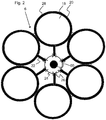
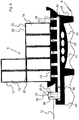
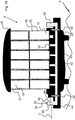
- Fig. 2 are a plurality of pressure vessel 20 via pressure vessel connections 22, which form both inlet and outlet of the respective pressure vessel 20 in the illustrated embodiment, connected to the centrally located sump 24 and together form the pressure storage system 30.
- the pressure vessel connections 22, each with a shut-off valve 26 are closed, so that individual pressure vessel 20, for example, for maintenance purposes, can be separated and brought to the surface.
- the sump 24 is arranged directly on the pump turbine unit 60.
- water is pumped out of the inner cavities 18 of the pressure vessels 20 into the surrounding sea 1 by means of a pump 16 (not shown) arranged in the pump turbine unit 60.
- the pump 16 sucks the water from the pump sump 24 and pumps the water through a water outlet 35 (not shown) directly into the surrounding sea 1.
- the inner cavities 18 of the artificial pressure vessel 20, in the example shown six inner cavities 18 of six pressure vessels 20th form one of the two reservoirs of the pumped storage power plant (the one with the lower potential energy).
- the fact that the pump 16 has to pump the water against the hydrostatic pressure PT prevailing in the water depth T causes a large amount of electrical energy consumed and converted into potential energy, as illustrated by the following examples.
- Fig. 3 shows the embodiment of the Fig. 2 in a side view, wherein the cylindrical shape of the pressure vessel 20 and the central arrangement of the pump turbine element 60 is further illustrated.
- the pressure vessels 20 are connected in the embodiment shown by means of pressure vessel connections 22 to the central pump turbine element 60.
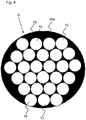
- Fig. 4 shows an alternative embodiment of the accumulator system with an integrated accumulator complex 20a.
- a plurality of internal pressure vessel elements 19 form a common accumulator volume 20a and are interconnected at one end of the integrated pressure accumulator complex 20a. In a standing position this end is the bottom of the integrated accumulator complex, which thus already forms the sump 24 of the accumulator complex, at which the water of the pressure vessel elements 19 can flow together.
- the pressure vessel elements 19 are formed from tubes, for example steel tubes or fiber concrete tubes, which are arranged standing next to each other. The wall 28 is then potted around the pipes so that the cavities and the area directed outwards to the sea water 1 are filled.
- the material thickness of the tubes is either chosen so that this is sufficient, the pressure of the outside To withstand water column, so that the wall 28 secures the pipes for purposes of statics against falling over and additionally complains the structure for sinking on the seabed 8. Otherwise, the material thickness of the pressure vessel elements 19 may also be selected to be thinner, so that the wall 28 of the integrated pressure accumulator complex 20a at the same time also withstands the pressure of the externally applied water column.
- Fig. 5 shows one to Fig. 4 similar embodiment of the pressure vessel 20 as an integrated pressure accumulator complex 20a, wherein the volume enclosed by the wall 28 is optimally utilized by the selection of various suitable pipe diameters of the individual inner pressure vessel elements 19. Possibly.
- the smaller cavities shown in the exterior of the integrated pressure accumulator complex 20a are also capable of being weighted with a ballast.
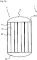
- Fig. 6 11 shows a side view of an integrated pressure accumulator complex 20a having a plurality of pressure vessel elements 19 and a wall 28 enclosing the pressure vessel elements 19.
- the integrated pressure accumulator complex 20a has a bottom 24 of the accumulator complex at the bottom and is connected via a pressure vessel connection 22 to a central pump turbine unit 60 (see FIG Fig. 7 ) hydraulically connected.
- the pressure vessel connection 22 is thus also water inlet and outlet of the integrated pressure accumulator complex 20a and may also be connected to further pressure vessels 20 (not shown).
- the integrated pressure accumulator complex 20a no mechanically moving parts or components of the power electronics for power generation or power destruction.
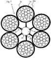
- Fig. 7 shows a schematic plan view of an underwater pumped storage power plant 6 with a central pumping turbine unit 60 and thus connected via pressure vessel connections 22 integral accumulator complexes 20a, each with a plurality of pressure vessel elements 19.
- the integral accumulator complexes 20a in this embodiment have no moving parts, since both the pump 16 as Also, the turbine 36 and shut-off valves 26 are integrated on or in the pump turbine unit 60.
- the shut-off valves 26 can separate the integral accumulator complexes 20a from the central pump turbine unit 60 in the event of an error or in the event of maintenance.
- the pump turbine unit 60 forms at the pump 16 also the hydrostatically lowest point, the sump 24, to which the water flows independently following the gravity.
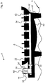
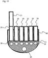
- Fig. 8 shows a further embodiment of the modular pumped storage power plant 6, wherein a bottom body 40 forms the base for receiving other components of the pumped storage power plant 6 and for its attachment or anchoring to the seabed 8.
- the bottom body 40 has in its interior side channels 43 for connecting the pressure accumulator 20 (see FIG. 9 ) with a main channel 42, which in turn is connected in the embodiment shown both with the turbine 16 and with the pump 36.
- the main channel 42 forms both the inlet from the turbine 16 to the pressure accumulators 20 and the flow from the pressure accumulators 20 to the pump 16, so that only one channel and thus possibly only one opening in the conversion of each pressure vessel is needed.
- a shut-off valve 26 is installed in each side channel 43, so that each of the Connection couplings 23 of the side channels 43 mounted pressure vessel 20 can be shut off and separated, for example, for maintenance purposes from the bottom body 40.
- the check valves 26 in the side channels 43 of the bottom body 40 allow to use a universal bottom piece in which, if only a smaller accumulator volume is needed, individual couplings 23 remain unused so that the bottom members are mass produced yet adapted to the particular application can be.
- the bottom body 40 has on its underside feet 46 which stand up for fixing the bottom body 40 on the seabed 8 or are sunk in the seabed 8 when the bottom body 40 rests on the seabed 8.
- Fig. 9 1 shows an embodiment of the pumped storage power plant 6 with bottom body 40, pump turbine unit 60, and a plurality of pressure vessels 20 mounted to couplings 23 of the floor body 40 which form a common modular accumulator volume and are supplied by the common pumping turbine unit 60 for filling and removal.
- a plurality of pump turbine units 60 be mounted on a bottom body 40 in order to increase the efficiency and the power output.
- an inlet / outlet valve 32 and the shut-off valves 26 of the side channels 43 are opened and the water flows through a water inlet 34 from the surrounding sea with the hydrostatic pressure PT corresponding to the water depth T.
- the recovered electrical energy is fed through the power line 12 in the general power grid.
- multiple water inlets 34 with valves 32 and turbines 36 may be present.
- the inner cavities 18 may be interspersed with struts or a supporting structure (not shown).
- the cross struts can fulfill a dual function, namely on the one hand to stabilize the pressure vessel 20 and on the other hand to generate turbulence in the flowing through the generator 36 in the inner cavity 18 water to prevent resonant vibrations in the pressure vessel 20.
- the pressure vessel 20 consists of a tubular concrete wall 28 with a connection coupling 23 at the bottom and possibly a further connection coupling 23 at the top, so that the pressure vessel 20 with the bottom body 40 and further pressure vessel 21 to the Pressure vessels 20 can be coupled.
- the wall thickness of the pressure vessel 20 and the bottom body 40 is selected as a function of the water depth T, in which the pumped storage power plant 6 is sunk and depending on the necessary mass so that it can still be sunk.
- the turbines 36 and the pumps 16 are disposed directly on the bottom body 40, for example, directly on the main channel 42 or on a boom 44 of the bottom body 40. In the embodiment shown are pump 16, turbine 36 and water inlet and outlet ports 34, 26 in one Pumpturbinenmaschine 60 integrated.
- the water is passed only over a short distance, namely only through the inlet or outlet opening 34, 26.
- the pumped storage power plant 6 therefore requires only electrical lines 4, 12 from the sea surface to the seabed 8, but not tubes or pipes for the transport of water. Possibly. can even meet an electrical line as power supply and -abtechnisch. It is also advantageous that the pressure difference is not greatly dependent on the level within the pressure vessel 20 due to the large water depth, so that the standing power is independent of the level is substantially constant.
- the bottom body 40 has in its wall 28 cavities 38, which are filled with bulk material, eg sand, to balance the mass of the pumped storage power plant 6.
- the pumped storage power plant 6, or its components bottom body 40 and pressure vessel 20, is preferably initially balanced so that it just floats when it is completely empty, so it can with a ship be transported to the place where it is to be sunk. Subsequently, at the sinking point of the bottom body 40 and / or the pressure vessel 20 with ballast water is weighted so far that the pumped storage power plant 6 sinks.
- the bottom body 40 can be sunk and the pressure vessels 20 are mounted on the bottom 8 to the bottom body 40 or the pressure vessels 20 are already attached to the connection couplings 23 of the bottom body 40 on the water surface and then the entire pumped storage power plant 6 is sunk.
- the amount of water used as ballast water is only the weighting and is not pumped out during normal operation, ie when storing and recovering the electrical energy so that the pumped storage power plant 6 in normal operation always has a greater mass than the displaced water and thus remains on the seabed 8.
- the ballast water can also be filled into the separate cavities 38.
- ballast water can be pumped out, so that the pumped storage power plant 6 reappears or at least so light that, for example, with the rope 52, which is marked at the sea surface with a buoy 54 ( please refer FIG. 1 ), can be caught up.
- the unfinished pressure vessel should be during the production so far protrude from the water that even in a storm, a full running of his inner cavity 18 is not possible.
- the thickness of the wall 28 of the pressure vessel 20 must once withstand the extremely large hydrostatic water pressure and also give the pressure vessel 20 such a high weight that the pumped storage power plant 6 sinks with at least almost empty inner cavity 18 on the seabed 8.
- reinforced concrete can be considered as wall material. The statics is carried out so that the pressure vessel 20 can withstand without damage higher pressures than on the seabed 8 are present.
- valves 26, 32, turbines 36, pumps 16, channels 42, 43 and / or electrical lines, etc. integrated, and the pressure vessel 20 are provided with connection couplings 23 so that they later their Function for many decades.
- the control and control electronics are also located directly on the bottom body 40 and is sunk with.
- Fig. 10 shows a side view of an integrated accumulator complex with several internal pressure vessel elements 19, as with FIGS. 4 and 5 was presented.
- the pressure vessel elements 19 are hydraulically connected to each other via a bottom body 40 and form a common pressure storage volume.
- a lid 46 is attached to the top.
- a pump turbine unit 60 is arranged, so that not separately for each of the pressure vessel elements 19 a pump and / or a turbine is to be used, but in an advantageous manner Way the pressure vessel elements 19 share the common infrastructure to pump (s) 16, turbine (s) 36 and the electrical power supply.
- the integrated accumulator complex with a plurality of pressure vessel elements 19 is thus an independent underwater pumped storage power plant 6.
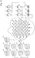
- FIG. 11 is a power grid 48 having a plurality of interconnected consumers 14 and a plurality of interconnected Windkraftanmaschine 2 and photovoltaic systems 3 shown, which form the primary power plants.
- the primary electric power generated by the primary power plants 2, 3 is by means of a plurality of pumped storage power plants 6 according to Fig. 2 to 4 cached.
- the many pumped storage power plants 6 are networked on the seabed 8 only by means of electric underwater lines 50 and provide if necessary, the recovered electrical energy over the existing part of the power supply network 48 to the consumer 14th
- FIGS. 12 to 14 a preferred manufacturing process is presented in which with reference to Fig. 12 First, a raw form of the bottom body 40 is made in a dock or harbor. It is made in such a way that it always floats straight and then towed somewhere in the sea for sinking and is sunk with some ballast on the seabed. If necessary, the dock in the harbor can be used as shuttering of the floor element 40.
- Fig. 13 are in the bottom body 40 already laid connecting pipes to the turbine and the pump, which take over the function of the previously described main channel 42 and the side channels 43 integrally in the bottom body 40.
- a soil weight or a filling compound 41 is filled in the bottom body 40, so poured in, for example, a concrete mass. The filling material can easily envelop the main and side channels 42, 43.
- the bottom body 40 may still be in the harbor or dock used for manufacturing, or may already be on the high seas.
- the pressure vessel 20, 21 are placed in the harbor by container crane on the bottom body 40 and anchored.
- Fig. 15 shows a further embodiment of the underwater pumped storage power plant. It's different from the one with Fig. 9 shown embodiment in that a second pump turbine block 62 is disposed on the bottom body 40, which can increase the power production, for example, in parallel operation and / or increases the reliability.
- the bottom body in this embodiment comprises two inlet / outlet valves, which are located in front of the respective pump turbine block 60, 62.
- the pressure vessels 20 are designed as simple tubes which are connected to each other and at the upper end of a common cover 46 have, for example, also just poured from concrete.
- the pressure vessels 20 are designed as spherical pressure vessels 20 and have simple pressure vessel connections 22.
- the pressure vessels are simply bolted together.
Description
Die Erfindung betrifft ein Pumpspeicherkraftwerk zum temporären reversiblen Speichern von Energie, insbesondere von zeitlich schwankend zur Verfügung stehender Energie aus Windkraftanlagen und/oder Photovoltaikanlagen, ein Stromversorgungsnetz mit einem Pumpspeicherkraftwerk sowie ein Verfahren zum reversiblen Zwischenspeichern von elektrischer Energie aus Primärenergiekraftwerken.The invention relates to a pumped storage power plant for the temporary reversible storage of energy, in particular temporally fluctuating available energy from wind turbines and / or photovoltaic systems, a power grid with a pumped storage power plant and a method for reversible caching of electrical energy from primary energy plants.
Als Folge der über die Erdoberfläche ungleichmäßig verteilten Sonneneinstrahlung entsteht eine bekannte Temperaturverteilung zwischen den Tropen und Subtropen auf der einen Seite und den Polarbereichen auf der anderen Seite. Dieses Energiegefälle ist ursächlich für die bekannten auf der Erde vorherrschenden Großwindsysteme, die einen Großteil der von der Erdoberfläche absorbierten Strahlungsenergie in Form von Wind im Falle der nördlichen Halbkugel u.a. nach Europa, Atlantik, Nordsee etc. transportieren.As a result of unevenly distributed solar radiation over the earth's surface, there is a known temperature distribution between the tropics and subtropics on one side and the polar regions on the other side. This energy gradient is responsible for the known large wind systems prevailing on earth, which absorb most of the radiant energy absorbed by the earth's surface in the form of wind in the case of the northern hemisphere and others. transport to Europe, Atlantic, North Sea etc.
Schon seit vielen Jahrhunderten nutzt der Mensch die Kraft des Windes, die im Mittel pro Quadratmeter Fläche einer Energieleistung von etwa 1 Kilowatt entspricht. Diese Energie kann mit Hilfe moderner Windkraftanlagen auch in Form von elektrischer Energie umgewandelt und vielfältig genutzt werden.For many centuries humans have been using the power of the wind, which corresponds on average to an energy output of about 1 kilowatt per square meter. This energy can be converted with the help of modern wind turbines in the form of electrical energy and used in many ways.
Windstärke und Windrichtung unterliegen dabei aber klimatischen und natürlichen Schwankungen, wobei der Wind auch regelmäßig zum Erliegen kommen kann. Eine industrielle Gesellschaft kann aber die Windkraft nur dann als verlässliche Energiequelle verwenden, wenn sie kontinuierlich zur Verfügung steht.Wind force and wind direction are subject but climatic and natural fluctuations, the wind can also come to a standstill regularly. An industrial society can only use wind power as a reliable source of energy if it is continuously available.
Eine Möglichkeit, eine kontinuierlichere Abgabe der elektrischen Energie an ein Stromversorgungsnetz o.ä. zu erreichen ist es, wenn man einen Teil der so erzeugten elektrischen Energie in ausreichendem Maße über den Zeitraum von zumindest Stunden, ggf. Tagen zwischenspeichern kann. Die Energie aus dem Zwischenspeicher kann dann bei einer Flaute in das Stromversorgungsnetz eingespeist werden, so dass eine kontinuierliche Abgabe gewährleistet ist. Gleiches gilt für elektrische Energie aus Photovoltaikanlagen.One way, a more continuous delivery of electrical energy to a power grid or similar. it is possible to achieve sufficient storage of a portion of the electrical energy generated over the period of at least hours, if necessary days. The energy from the buffer can then be fed in a doldrums in the power grid, so that a continuous delivery is guaranteed. The same applies to electrical energy from photovoltaic systems.
Gelingt eine solche Speicherung in großem Maßstab, so könnten diese regenerativen Energiequellen besser zur Grundlastdeckung eingesetzt werden und eines Tages möglicherweise fossile Energieerzeugung und Kernenergie vollständig ersetzen.If such storage is successful on a large scale, then these regenerative energy sources could be better used for base load coverage and could one day possibly completely replace fossil energy generation and nuclear energy.
Traditionelle Direktspeicher für Elektrizität, wie Akkumulatoren, können nur vergleichsweise geringe Energiemengen speichern, weisen hohe Speicherverluste auf und sind außerdem sehr teuer und daher im großen Stil wirtschaftlich nicht verwendbar. Die heute häufig diskutierten chemischen Speicherverfahren (z.B. Elektrolyse von Wasser) und Druckluftspeicher haben schon aufgrund der Wärmeverluste eine relativ schlechte Effizienz in der Wiedergewinnung der so gespeicherten Energie. Eine Nutzungseffizienz in der Größenordnung von etwa 30% sind für diese Speicherarten bereits gute Werte.Traditional direct storage for electricity, such as batteries, can store only comparatively small amounts of energy, have high memory losses and are also very expensive and therefore not economically viable on a large scale. The chemical storage methods (eg electrolysis of water) and compressed air storage, which are frequently discussed today, have already started due to the Heat losses a relatively poor efficiency in the recovery of the stored energy. Usage efficiency of the order of about 30% is already good for these types of storage.
Daher verbleiben nach heutigem Stand der Technik nur Wasser-Pumpspeicherkraftwerke (PSKW) um effizient und in großem Maße elektrische Energie zu speichern. Diese können eine Wiedergewinnungseffizienz der gespeicherten Energie von etwa 80% erreichen. Bei diesen Anlagen pumpt man Wasser - zumeist an künstlichen Stauseen - in Zeiten des Stromüberflusses aus einem unteren Speicherbecken in ein oberes Speicherbecken. Je größer die Speicherbecken und je größer der Höhenunterschied ist, desto mehr Energie kann man speichern. Bei Strombedarf lässt man das so hochgepumpte Wasser durch Turbinen wieder zurück in den unteren Speicher fließen. Dabei wird die Differenz der potentiellen Energie des Wassers in elektrische Energie umgewandelt. Die Leistung W ergibt sich aus dem Produkt aus Höhenunterschied h zwischen beiden Speicherbecken und der Wasserdurchflussmenge M. Es gilt (bei einer Dichte des Wassers von 1000 kg/m3) die einfache Formel:
![]()
![]()
![]()
![]()
Der Bedarf an solchen Pumpspeicherkraftwerken übersteigt jedoch das typischerweise vorhandene Potential und vor allem für die Offshore gewonnene Windenergie werden ortsnahe Energiespeicher gebraucht. Diese Kapazitäten auszubauen, ist daher eine wichtige volkswirtschaftliche Aufgabe (siehe z.B. Energie-Forschungszentrum Niedersachsen, Goslar, http://www.efzn.de). Als mögliche Ausbaukapazitäten werden zurzeit die Errichtung neuer Pumpspeicherkraftwerke in Gebirgen und in alten Bergwerken diskutiert. Die Nutzung von unterirdischen Bergwerksanlagen erfordert einen großen überirdischen Wasserspeicher. Dessen Errichtung scheitert oft an vorhandener Wohnbebauung oder anderer gegebener Nutzung. Außerdem sind die vorhandenen Volumina in Bergwerksanlagen klein und über lange unterirdische Strecken verteilt, so dass leistungsfähige Kraftwerke nur schwierig zu realisieren sind. Die Speicherung erfordert ferner teilweise lange Stromtransportwege und einen schmerzhaften Eingriff in den Naturhaushalt. Grundsätzlich ist die Verfügbarkeit von geeigneten Standorten für derartige Pumpspeicherkraftwerke weltweit begrenzt.However, the demand for such pumped storage power plants exceeds the typically existing potential, and especially for offshore wind energy, local energy storage systems are needed. To expand these capacities is therefore an important economic task (see eg Energy Research Center Niedersachsen, Goslar, http://www.efzn.de). Possible construction capacities are currently being discussed for the construction of new pumped storage power plants in mountains and in old mines. The use of underground mines requires a large underground water reservoir. Its establishment often fails due to existing residential development or other given use. In addition, the existing volumes in mining plants are small and distributed over long underground routes, so that efficient power plants are difficult to implement. The storage also requires sometimes long Stromtransportwege and a painful intervention in the natural environment. Basically, the availability of suitable locations for such pumped storage power plants worldwide is limited.
Daher wird hier ein völlig anderer, auf den ersten Blick vielleicht unrealistisch erscheinender Ansatz für neue Pumpspeicherkraftwerke vorgestellt.Therefore, a completely different, at first glance perhaps unrealistic approach for new pumped storage power plants is presented.
Die deutsche Patentanmeldung
Die
Die
Es ist eine Aufgabe der Erfindung ein neuartiges Pumpspeicherkraftwerk bereit zu stellen, welches durch einen modularen Aufbau nahezu beliebig skalierbar ist und eine enorme Speicherkapazität zur Verfügung stellen kann, ohne die vorhandene Landschaft zu belasten.It is an object of the invention to provide a novel pumped storage power plant, which is almost arbitrarily scalable by a modular design and can provide an enormous storage capacity without burdening the existing landscape.
Die Aufgabe der Erfindung wird durch den Gegenstand der unabhängigen Ansprüche gelöst. Vorteilhafte Weiterbildungen der Erfindung sind in den Unteransprüchen definiert.The object of the invention is solved by the subject matter of the independent claims. Advantageous developments of the invention are defined in the subclaims.
Die Erfindung nutzt den Grundgedanken, das Meer als oberes Speicherbecken oder Wasserreservoir eines Pumpspeicherkraftwerkes zu nutzen. Als unteres Speicherbecken oder Wasserreservoir dienen auf den Meeresboden abgesenkte Druckbehälter. Das untere Wasserreservoir (dasjenige mit der niedrigeren potentiellen Energie) ist demnach ein künstlich erschaffener Raum, insbesondere ein Hohlraum, der von dem Druckbehälter gebildet wird.The invention uses the basic idea to use the sea as the upper reservoir or water reservoir of a pumped storage power plant. As a lower storage tank or water reservoir are lowered to the seabed pressure vessel. The lower water reservoir (the one with the lower potential energy) is therefore an artificially created space, in particular a cavity, which is formed by the pressure vessel.
Erfindungsgemäß wird ein Unterwasser-Pumpspeicherkraftwerk zum temporären reversiblen Zwischenspeichern von elektrischer Energie aus anderen Kraftwerken, insbesondere zeitlich schwankend stromerzeugenden Kraftwerken, z.B. Windkraftanlagen oder Photovoltaikanlagen, bereit gestellt. Wie jedes Pumpspeicherkraftwerk benutzt auch dieses Pumpspeicherkraftwerk ein erstes und zweites Wasserreservoir, wobei das Wasser in dem zweiten Wasserreservoir eine höhere potentielle Energie aufweist als in dem ersten Wasserreservoir. Zum temporären reversiblen Speichern der elektrischen Energie wird Wasser von dem ersten Wasserreservoir in das zweite Wasserreservoir gepumpt und zum Wiedergewinnen der elektrischen Energie lässt man das Wasser aus dem zweiten Wasserreservoir in das erste Wasserreservoir zurückfließen, wobei ein Generator die beim "Hochpumpen" deponierte potentielle Energie wieder in elektrische Energie verwandelt. Zum Speichern und Wiedergewinnen der elektrischen Energie kommt es lediglich auf die Differenz der potentiellen Energie einer Wassermenge zwischen den beiden Wasserreservoiren an. Bei einem herkömmlichen Pumpspeicherkraftwerk wird diese durch die Höhendifferenz zwischen den beiden Becken definiert.According to the invention, an underwater pumped storage power plant for the temporary reversible caching of electrical energy from other power plants, in particular temporally fluctuating power-generating power plants, e.g. Wind turbines or photovoltaic systems, provided. Like any pumped storage power plant, this pumped storage power plant also uses a first and a second water reservoir, wherein the water in the second water reservoir has a higher potential energy than in the first water reservoir. For temporarily reversibly storing the electrical energy, water is pumped from the first water reservoir into the second water reservoir, and to recover the electrical energy, the water from the second water reservoir is returned to the first water reservoir, with a generator recovering the potential energy deposited during "pump up" transformed into electrical energy. For storing and recovering the electrical energy, all that matters is the difference in the potential energy of a quantity of water between the two water reservoirs. In a conventional pumped storage power plant this is defined by the height difference between the two basins.
Bei der vorliegenden Erfindung wird nun das erste Wasserreservoir mit der niedrigeren potentiellen Energie durch ein Druckspeichersystem aus künstlichen, mit Wasser befüllbaren Druckbehältern gebildet, welches in großer Tiefe auf den Meeresgrund versenkt wird. Das Druckspeichersystem ist dabei derart druckfest gebaut, dass es in der erwünschten Meerestiefe formstabil gegen den hydrostatischen Wasserdruck ist, wenn es leergepumpt wird.In the present invention, the first water reservoir with the lower potential energy is now formed by an accumulator system of artificial, water-filled pressure vessels, which is sunk at great depth to the seabed. The Pressure accumulator system is constructed so pressure resistant that it is dimensionally stable in the desired depth of the sea against the hydrostatic water pressure when it is pumped out.
Das zweite Wasserreservoir mit der höheren potentiellen Energie wird durch das Meer selbst gebildet, welches den Druckbehälter umgibt. Wenn man nun Wasser in das in einer Wassertiefe T versenkte Druckspeichersystem einströmen lässt, wird diejenige potentielle Energie frei, welche der Höhendifferenz zur Meeresoberfläche, also der Wassertiefe T entspricht. Pumpt man anschließend das Wasser wieder aus dem Druckspeichersystem gegen den hydrostatischen Druck PT in der Wassertiefe T in das umgebende Meer, muss man elektrische Energie entsprechend der Wassersäule die auf dem Druckspeichersystem in der Wassertiefe T lastet aufwenden und kann diese somit speichern; selbstverständlich vermindert um die sonst auch üblichen Verlustleistungen.The second water reservoir with the higher potential energy is formed by the sea itself, which surrounds the pressure vessel. If water is now allowed to flow into the pressure accumulator system which has sunk into a water depth T, the potential energy which corresponds to the height difference to the sea surface, ie the water depth T, becomes free. If you then pump the water back from the accumulator system against the hydrostatic pressure PT in the water depth T in the surrounding sea, you have to spend electrical energy corresponding to the water column on the pressure accumulator system in the water depth T lastet and can thus store them; of course reduced by the otherwise usual power losses.
Da das Wasser aus dem Druckspeichersystem ohne nachströmende atmosphärische Luft herausgepumpt wird, und daher ein nur durch den Partialdruck des Wasserdampfes begrenztes Vakuum entsteht, muss streng genommen der atmosphärische Luftdruck noch zum hydrostatischen Druck der Wassersäule hinzuaddiert werden. Quantitativ spielt dies jedoch bei den hier vornehmlich anvisierten großen Meerestiefen keine Rolle; bei einer Anwendung in einem See mit geringer Tiefe sollte man das zusätzliche Bar des Atmosphärendruck, welches einer zusätzlichen Tiefe von 10 m entspricht, jedoch in die Berechnung einbeziehen.Since the water is pumped out of the accumulator system without inflowing atmospheric air, and therefore creates a limited only by the partial pressure of the water vapor vacuum, strictly speaking, the atmospheric pressure has to be added to the hydrostatic pressure of the water column. Quantitatively, however, this does not play a role in the great sea depths that are primarily aimed at here; however, for use in a shallow lake, the additional bar of atmospheric pressure, which corresponds to an additional depth of 10 m, should be included in the calculation.
Mit anderen Worten verbleibt im Inneren des Druckspeichersystems zumindest ein Wasserdampfdruck. Der Wasserdampfdruck im Inneren des Druckspeichersystems ist in der Größenordnung von zirka 100 mbar oder mehr als 100 mbar.In other words, at least one water vapor pressure remains in the interior of the pressure accumulator system. The water vapor pressure in the interior of the pressure storage system is of the order of approximately 100 mbar or more than 100 mbar.
Das Druckspeichersystem des Unterwasser-Pumpspeicherkraftwerks weist zum Speichern des Wassers zumindest zwei mit Wasser befüllbare Druckbehälter auf, welche ein gemeinsames Druckspeichervolumen bilden. Die Druckbehälter können beispielsweise miteinander koppelbar oder fest verbindbar sein, so dass ein modular aufgebautes Druckspeichersystem gebildet ist. Vorzugsweise werden als Druckbehälter leicht zusammensetzbare Module verwendet, wie beispielsweise zylinder- bzw. rohrförmige oder polyeder- bzw. würfelförmige Druckbehälter, die eine gute Volumenausnutzung gewährleisten, wenn mehrere dieser Druckbehälter benachbart aufgestellt werden.The accumulator system of the underwater pumped storage power plant has to store the water at least two water-filled pressure vessel, which form a common accumulator volume. The pressure vessels may, for example, be coupled together or fixedly connectable, so that a modular pressure accumulator system is formed. Preferably, easily assembled modules are used as pressure vessel, such as cylindrical or tubular or polyhedral or cube-shaped pressure vessels, which ensure good volume utilization, if several of these pressure vessels are placed adjacent.
Die Druckbehälter weisen bevorzugt keine beweglichen Teile auf. Das bedeutet, dass keine mechanischen bzw.
elektrischen Leistungskomponenten in oder an dem Druckbehälter installiert sind, die zur Stromerzeugung oder Stromvernichtung verwendet werden (Pumpe, Turbine).The pressure vessels preferably have no moving parts. This means that no mechanical or
electrical power components are installed in or on the pressure vessel used for power generation or power destruction (pump, turbine).
Erfindungsgemäß sind die Druckbehälter des Druckspeichersystems über einen Sumpf miteinander verbunden. Der Sumpf bildet den tiefsten oder zumindest einen der tiefsten Punkte des Druckspeichersystems, so dass sich das Wasser, beispielsweise durch einfache Ausnutzung der Schwerkraft, stets im Sumpf sammelt.According to the invention, the pressure vessels of the pressure accumulator system are connected to one another via a sump. The sump forms the lowest or at least one of the deepest points of the accumulator system, so that the water always collects in the sump, for example by simple utilization of gravity.
Das Druckspeichersystem weist zum Ausströmenlassen des Wassers einen an dem Sumpf angeordneten Wasserauslass mit einer unmittelbar an dem Wasserauslass angeordneten Pumpe auf. Mit der Pumpe wird das Wasser aus dem Druckspeichersystem unmittelbar in das umgebende Meer gegen den der Wassertiefe entsprechenden hydrostatischen Druck PT gepumpt, wobei die Pumpe elektrische Energie in die der verdrängten Wassersäule entsprechende potentielle Energie umwandelt.The pressure accumulator system has for discharging the water to a arranged on the sump water outlet with a pump disposed directly on the water outlet. With the pump, the water is pumped from the accumulator system directly into the surrounding sea against the hydrostatic pressure corresponding to the water depth PT, the pump converts electrical energy into the potential energy corresponding to the displaced water column.
Bei dem Auspumpvorgang des Wassers aus dem Druckspeichersystem ist zur Vermeidung von Kavitationsvorgängen an der Pumpe ein an der Pumpe anliegender Rest-Vordruck im Druckspeichersystem vorteilhaft. So zeigen Berechnungen, dass ohne nachströmende atmosphärische Luft, oder ein anderes Gas, eine an der Pumpe anliegende Wassersäule von 15 Metern ausreicht, um die Kavitation zu verringern oder sogar zu vermeiden. Demgemäß ist es von Vorteil, diese Größe in die Bauform des Druckspeichersystems bzw. in die Anbringung des Wasserballasts einfließen zu lassen. Ggf. ist es aus diesem Grund auch vorteilhaft, jeden Druckbehälter mit einer Vorpumpe auszurüsten, die für die Pumpe einen Vordruck erzeugt.In the pumping out of the water from the accumulator system to avoid cavitation processes on the pump an applied to the pump residual pre-pressure in the accumulator system is advantageous. Thus, calculations show that, without any inflowing atmospheric air or any other gas, a 15-meter water column attached to the pump is sufficient to reduce or even prevent cavitation. Accordingly, it is advantageous to incorporate this size in the design of the accumulator system or in the attachment of the water ballast. Possibly. For this reason, it is also advantageous to equip each pressure vessel with a forepump, which generates a pre-pressure for the pump.
Die Bauform des Druckspeichersystems kann also derart ausgeführt sein, dass die Pumpe im Bereich des Sumpfes angeordnet wird und die in dem Unterwasser-Pumpspeicherkraftwerk herrschende Wassersäule zzgl. des Dampfdrucks einen Wassersäulenvordruck von äquivalent zirka 15 Metern Wassersäule an der Pumpe erzeugt. Dieser Vordruck ist besonders vorteilhaft, da hierdurch derzeit handelsübliche großtechnische Pumpen eingesetzt werden können. Darüber hinaus kann beim Anliegen eines Wassersäulenvordruck an der Pumpe von derzeit mindestens 15 Metern auf eine Belüftung des Druckbehälters verzichtet werden.The design of the pressure accumulator system can thus be designed such that the pump is arranged in the region of the sump and prevailing in the underwater pumped storage power plant water column plus. The vapor pressure generates a water column upstream of equivalent about 15 meters of water at the pump. This form is particularly advantageous because it is currently commercial large-scale pumps can be used. In addition, it can be dispensed with aeration of the pressure vessel at the present at least 15 meters when applying a water column pre-pressure on the pump.
Das Unterwasser-Pumpspeicherkraftwerk weist ferner einen Wassereinlass mit einem unmittelbar an dem Wassereinlass angeordneten Generator auf. Vorzugsweise wird ein gemeinsamer Generator für die zumindest zwei bzw. alle Druckbehälter verwendet, so dass der gemeinsame Generator im Stromerzeugungsbetrieb über den Wassereinlass die von dem Druckspeichersystem umfassten zumindest zwei Druckbehälter füllt, vorzugsweise gleichmäßig. Beim Einströmenlassen des Wassers unmittelbar aus dem umgebenden Meer mit dem der Wassertiefe entsprechenden hydrostatischen Druck in das Druckspeichersystem wandelt der Generator die potentielle Energie der zuvor verdrängten Wassersäule wieder in entsprechende elektrische Energie um. Das Druckspeichersystem weist ferner Ventile am Einlass und Auslass auf, um diese zu verschließen, wenn nicht gerade Energie gespeichert, beziehungsweise zurück gewonnen wird. Das Auspumpen und Einströmen des Wassers erfolgt demnach lediglich auf kurzem Weg in das bis auf den Wassereinlass und Wasserauslass geschlossene Druckspeichersystem.The underwater pumped storage power plant also has a water inlet with a generator arranged directly on the water inlet. Preferably, a common generator is used for the at least two or all pressure vessels, so that the common generator in the power generation operation via the water inlet fills the at least two pressure vessels comprised by the pressure storage system, preferably evenly. When flowing the water directly from the surrounding sea with the hydrostatic pressure corresponding to the depth of water in the accumulator system, the generator converts the potential energy of the previously displaced water column again into corresponding electrical energy. The accumulator system further includes valves at the inlet and outlet to close them when not just stored energy, or recovered. The pumping and inflow of the water is therefore only a short path in the closed up to the water inlet and outlet pressure accumulator system.
Wenn man demnach das Druckspeichersystem in einer Tiefe von z.B. 2000 m unter der Meeresoberfläche versenkt, entspricht dies einem Pumpspeicherkraftwerk, bei welchem das zweite Wasserreservoir 2000 m oberhalb des ersten Wasserreservoirs liegt, was für übliche Pumpspeicherkraftwerke bereits ein außergewöhnlich großer Höhenunterschied ist. Verblüffenderweise benötigt man trotzdem keine langen Rohre um das zum Speichern der elektrischen Energie verwendete Wasser über eine Strecke von 2000 m (bei ungleich 90° Steigung sogar noch mehr) zu transportieren. Es genügt nämlich, das Wasser vom Inneren des Druckspeichersystems lediglich nach außen in das umgebende Meer zu pumpen, was nur eine Strecke von einigen wenigen Metern bedeutet und entsprechend wieder zurückströmen zu lassen. Bereits auf dieser kurzen Pumpstrecke wird die nur durch die Druckunterschiede aufgebaute Potentialdifferenz überwunden. Die von der Gravitation verursachte Potentialdifferenz wird nämlich ohne Überwindung dieser Wegstrecke allein durch die in der Wassertiefe T auf dem Druckbehälter lastende Wassersäule aufgebracht. Es werden daher weder Rohre zum Transport von Wasser noch Luftleitungen zwischen dem Druckbehälter und der Meeresoberfläche benötigt. Man nutzt einfach die Potentialdifferenz der Meerestiefe in Relation zum Innendruck des Druckspeichersystems, wobei nicht ausgeschlossen sein soll, dass das Pumpspeicherkraftwerk in einem tiefen Binnensee versenkt wird. Man benötigt daher lediglich elektrische Leitungen zum Transport der elektrischen Energie von der Meersoberfläche zu dem Druckspeichersystem und zurück.Accordingly, if the pressure accumulator system is sunk at a depth of, for example, 2000 m below the sea surface, this corresponds to a pumped storage power plant in which the second water reservoir is 2000 m above the first water reservoir, which is already an unusually large difference in height for conventional pumped storage power plants. Surprisingly, you still do not need long tubes to transport the water used to store the electrical energy over a distance of 2000 m (even more than 90 ° slope). Suffice it to pump the water from the interior of the accumulator system only to the outside in the surrounding sea, which means only a distance of a few meters and to let flow back accordingly. Already on this short pumping section, the potential difference built up only by the pressure differences is overcome. The potential difference caused by the gravitation is applied without overcoming this distance alone by the pressure acting in the water depth T on the pressure vessel water column. Therefore, neither pipes for transporting water nor air ducts between the pressure vessel and the sea surface are required. One simply uses the potential difference of the sea depth in relation to the internal pressure of the accumulator system, which should not be ruled out that the pumped storage power plant is sunk in a deep lake. Therefore, it only requires electrical lines to transport the electrical energy from the sea surface to the accumulator system and back.
Mit der Erfindung wird darüber hinaus eines der zwei Speicherbecken oder definierten Wasserreservoire völlig "eingespart", da das umgebende Meer selbst das zweite Wasserreservoir (mit der höheren potentiellen Energie) bildet. Das erste Wasserreservoir wird von dem Innenraum des Druckspeichersystems in Form von insbesondere modular koppelbaren Druckbehältern oder Drucktanks gebildet. Somit bilden die Drucktanks ein abgeschlossenes Wasser-Speichervolumen, nämlich dasjenige Wasser-Speichervolumen oder Wasserreservoir mit der niedrigeren potentiellen Energie gegenüber dem umgebenden Meer. Dadurch werden lange Wasserrohre, die bei herkömmlichen Pumpspeicherkraftwerken die Höhendifferenz überbrücken müssen, eingespart. Dies vereinfacht nicht nur den Aufbau, sondern es werden auch Reibungsverluste beim Transport des Wassers reduziert, wodurch der Wirkungsgrad erhöht werden kann. Ferner kann das Druckspeichervolumen derart modular gebildet sein, dass derartige Druckbehälter in großer Zahl auf dem Meeresgrund versenkt werden und miteinander gekoppelt werden, um ein hinreichend großes Wasser-Speichervolumen und damit die erwünschte Energie-Speicherkapazität zu erreichen ohne die oberirdisch nutzbare Landschaft zu belegen. Bei einer Vielzahl von Druckbehältern verwenden diese somit die gemeinsame(n) Pumpe(n) und gemeinsame(n) Generator(en), so dass die Druckbehälter ein gemeinsames Druckspeichervolumen bilden und mehrere Pumpen und/oder Generatoren eingespart werden können.With the invention, moreover, one of the two storage tanks or defined water reservoirs is completely "saved", since the surrounding sea itself forms the second water reservoir (with the higher potential energy). The first water reservoir is formed by the interior of the pressure accumulator system in the form of particularly modularly coupled pressure vessels or pressure tanks. Thus, the pressure tanks form a sealed water storage volume, namely the water storage volume or reservoir with the lower potential energy compared to the surrounding sea. As a result, long water pipes, which need to bridge the height difference in conventional pumped storage power plants, saved. This not only simplifies the construction, but it also reduces friction losses during transport of the water, whereby the efficiency can be increased. Furthermore, the accumulator volume can be formed in a modular manner, such that large numbers of such pressure vessels are sunk on the seabed and coupled together to reach a sufficiently large water storage volume and thus the desired energy storage capacity without occupying the above-ground landscape. With a plurality of pressure vessels, these thus use the common pump (s) and common generator (s), so that the pressure vessels form a common pressure storage volume and several pumps and / or generators can be saved.
Es kann auch eine Vielzahl solcher Pumpspeicherkraftwerke auf dem Meeresboden installiert sein. Vorzugsweise umfasst ein solches Netz aus Unterwasser-Pumpspeicherkraftwerken demnach eine Mehrzahl von auf dem Meeresgrund befindlichen Druckspeichersystemen, welche auf dem Meeresgrund mit einem Netzwerk aus elektrischen Leitungen elektrisch miteinander verbunden sind. Eine Vernetzung mit Wasserrohren zwischen den jeweils mit eigener Pumpe und Generator ausgestatteten Druckspeichersystemen ist nicht notwendig.It can also be a variety of such pumped storage power plants installed on the seabed. Preferably, such a network of subsea pumped storage power plants accordingly comprises a plurality of pressure accumulator systems located on the seabed, which are electrically connected to each other on the seabed with a network of electrical lines. Networking with water pipes between each equipped with its own pump and generator accumulator systems is not necessary.
Die Installation eines Druckspeichersystems weist vielfältige Vorzüge auf. Zum Einen lässt sich so ein modular aufbaubares Pumpspeicherkraftwerk bereitstellen, welches eine an den Verwendungszweck und Einsatzort angepasste Größe aufweist und somit geringere Kosten verursacht. Des Weiteren ist die Auswahl und Konstruktion von geeigneten Druckbehältern vereinfacht, da bauseitig (der Druckbehälter ist ein Bauwerk mit im gefüllten Zustand erheblichem Eigengewicht) und konstruktiv optimale Druckbehälter verwendet werden können und darüber hinaus das Druckspeichervolumen an die Leistungsfähigkeit geeigneter Pump- und Turbinenaggregate angepasst werden kann. Mehrere Druckbehälter lassen sich demnach hydraulisch zu einem Druckspeichersystem zusammenschalten und die Befüllung und Entleerung erfolgt nur an einem einzigen Punkt. Natürlich müssen die hydraulischen Verbindungen so beschaffen sein, dass ein unbehindertes Zu- und Abfließen des Wassers ermöglicht wird.The installation of an accumulator system has many advantages. For one thing, that's the way to go provide modular buildable pumped storage power plant, which has a size adapted to the purpose and location and thus causes lower costs. Furthermore, the selection and construction of suitable pressure vessels is simplified because on-site (the pressure vessel is a building with considerable weight when filled) and structurally optimal pressure vessel can be used and beyond the pressure accumulator volume can be adapted to the performance of suitable pump and turbine units , Accordingly, several pressure vessels can be connected hydraulically to form an accumulator system and the filling and emptying takes place only at a single point. Of course, the hydraulic connections must be such as to allow unimpeded inflow and outflow of the water.
Vorzugsweise weist die Verbindung der Druckbehälter mit dem Sumpf zumindest ein Absperrventil zum Trennen zumindest eines der Druckbehälter vom Druckspeichersystem auf, so dass auch ein einzelner Druckbehälter für Wartungszwecke oder bei Leckagen vom übrigen Druckspeichersystem getrennt werden kann.The connection of the pressure vessels with the sump preferably has at least one shut-off valve for separating at least one of the pressure vessels from the pressure storage system, so that a single pressure vessel can be separated from the rest of the pressure storage system for maintenance purposes or in the case of leakages.
Die Modularität des Unterwasser-Pumpspeicherkraftwerks kann dadurch weiter gesteigert werden, dass eine Pumpturbineneinheit vorgesehen wird, die insbesondere den Wassereinlass, den Wasserauslass, die gemeinsame Pumpe und den Generator sowie die zur Verbindung mit den elektrischen Leitungen nötige Elektroinstallation beherbergt.The modularity of the underwater pumped storage power plant can be further enhanced by providing a pumping turbine unit which accommodates, in particular, the water inlet, the water outlet, the common pump and the generator as well as the electrical installation necessary for connection to the electrical lines.
Die Pumpturbineneinheit ist insbesondere von den übrigen Komponenten, wie beispielsweise dem Druckspeichersystem des Unterwasser-Pumpspeicherkraftwerks, abkoppelbar. Die abkoppelbare Pumpturbineneinheit kann somit getrennt beispielsweise zu Wartungszwecken zur Wasseroberfläche geholt werden.
Das Druckspeichersystem sollte ein Volumen aufweisen, welches eine signifikante Energiespeicherung ermöglicht, das Druckspeichervolumen sollte daher mindestens 100 oder 1000 Kubikmeter betragen, kann aber um ein Vielfaches, ggf. mehrere Größenordnungen größer sein. Es sind sogar Volumina im Bereich von einer Million Kubikmeter oder mehr denkbar. Je größer die einzelnen Druckbehälter sind, umso geringer ist die benötigte Anzahl.The pump turbine unit can be decoupled in particular from the other components, such as the pressure storage system of the underwater pumped storage power plant. The disconnectable pump turbine unit can thus be brought separately, for example for maintenance purposes to the water surface.
The accumulator system should have a volume that allows significant energy storage, the accumulator volume should therefore be at least 100 or 1000 cubic meters, but may be many times, possibly several orders of magnitude larger. Even volumes in the range of one million cubic meters or more are conceivable. The larger the individual pressure vessels, the lower the required number.
Beispielsweise können große industriell gefertigte Zylinderrohre oder auch elementare Kugeltanks als Druckbehälter verwendet werden. Ein Kugeltank mit 100 Metern Durchmesser hat ein Volumen von etwa 500.000 Kubikmeter. Lässt man 50 Kubikmeter Wasser pro Sekunde durch die Turbinen strömen, dann liefert dieses Pumpspeicherkraftwerk bei 2000 m Wassertiefe eine Leistung von etwa 1 Gigawatt für eine Zeitdauer von etwa 3 Stunden. Durch die Verbindung von mehreren solcher Zylinderrohre oder elementaren Kugeltanks zu einem Druckspeichersystem kann entweder diese Leistung entsprechend erhöht oder eine noch größere Speicherkapazität erreicht werden. Die Speicherung von regenerativ erzeugter Energie ist hiermit in großen Mengen und ohne nennenswerte Verluste möglich.For example, large industrial cylinder tubes or elementary spherical tanks can be used as a pressure vessel. A spherical tank with a diameter of 100 meters has a volume of about 500,000 cubic meters. With 50 cubic meters of water flowing through the turbines per second, this pumped-storage power plant delivers approximately 1 gigawatt of power for about 3 hours at 2000 meters of water. By connecting a plurality of such cylinder tubes or elementary ball tanks to a pressure accumulator system, either this power can be correspondingly increased or even greater storage capacity can be achieved. The storage of regeneratively generated energy is hereby possible in large quantities and without appreciable losses.
Zweckmäßigerweise bestehen die Druckbehälter aus Stahl und/oder Beton, insbesondere Faserbeton, d.h. weisen eine entsprechende dreidimensional geschlossene Außenwandung z.B. aus Stahl- oder Faserbeton auf. Hiermit lässt sich ein hinreichend druckfester Druckbehälter bzw. Hohlkörper bauen. Eine mögliche Bauform des Druckbehälters weist beispielsweise ein inneres Tragwerk zur Stützung gegen den Wasserdruck auf, wobei das innere Tragwerk nicht den Abfluss des Wassers in dem Druckbehälter hin zum Sumpf behindern sollte.Conveniently, the pressure vessel made of steel and / or concrete, in particular fiber concrete, ie have a appropriate three-dimensional closed outer wall, for example made of steel or fiber concrete. This makes it possible to build a sufficiently pressure-resistant pressure vessel or hollow body. A possible design of the pressure vessel has, for example, an inner structure for support against the water pressure, wherein the inner structure should not hinder the outflow of water in the pressure vessel towards the swamp.
Vorzugsweise wird der Druckbehälter so massiv gebaut bzw. beschwert, dass er im ausgepumpten Zustand im Normalbetrieb eine Masse hat, die etwas größer ist, als die Masse des von dem Druckbehälter verdrängten Wassers, so dass der Druckbehälter auch im ausgepumpten Zustand im Normalbetrieb im Meer nach unten sinkt, so dass sich der Verankerungsaufwand auf dem Meeresgrund in Grenzen hält. Ggf. kann der Druckbehälter sogar ohne wesentliche Verankerung einfach auf dem Meeresgrund liegen, wenn er in jedem Füllzustand im Normalbetrieb schwer genug ist. Dennoch soll nicht ausgeschlossen sein, dass der Druckbehälter geringfügig leichter als das verdrängte Wasser ist und der Druckbehälter am Meeresgrund verankert wird.Preferably, the pressure vessel is built so massive or weighted that it has a mass in the pumped state in normal operation, which is slightly larger than the mass of displaced from the pressure vessel water, so that the pressure vessel in the pumped state in normal operation in the sea sinks down, so that the anchoring effort on the seabed is limited. Possibly. The pressure vessel can even lie on the seabed even without substantial anchorage, if it is heavy enough in any state of filling in normal operation. Nevertheless, it should not be ruled out that the pressure vessel is slightly lighter than the displaced water and the pressure vessel is anchored to the seabed.
In vorteilhafter Weise weisen die Druckbehälter des Druckspeichersystems separate Hohlräume auf, z.B. in der Umwandung, wobei Schüttgut als Beschwerungsmaterial in die Hohlräume eingefüllt werden kann. Hiermit kann die Masse des Druckspeichersystems im Nachhinein noch angepasst werden, um sie so zu beschweren, dass sie auf den Meeresgrund sinken. Besonders vorteilhaft ist es aber, die Hohlräume mit dem Schüttgut zunächst so auszutarieren, dass das Druckspeichersystem und/oder der Bodenkörper gerade noch schwimmt und dann vor Ort auf dem Meer zusätzliches Ballastwasser einzufüllen. Das Beschwerungsmaterial kann in kostengünstiger Weise natürliches Schüttgut sein, z.B. Sand, Kies, Schlick oder Ähnliches, dessen Masse vor Ort mit in das Schüttgut eingebrachtem Wasser zusätzlich vergrößert werden kann, um die Masse vor Ort noch genauer auszutarieren. Durch das Einbringen von Ballastwasser in das Schüttgut kann die Masse soweit erhöht werden, dass das Pumpspeicherkraftwerk versinkt, es können aber auch separate Hohlräume mit Ballastwasser gefüllt werden, damit das Ballastwasser einfacher wieder herausgepumpt werden kann, um das ganze Pumpspeicherkraft oder auch nur einzelne Komponenten des Pumpspeicherkraftwerks wieder aufzuholen. Der Gesamt-Ballast ist jedenfalls so bemessen, dass er das Pumpspeicherkraftwerk im Normalbetrieb auf dem Meeresgrund hält. Die Gewichtsverteilung, z.B. die Anordnung des Ballasts kann asymmetrisch sein, damit der einzelne Druckbehälter des Druckspeichersystems bzw. das ganze Unterwasser-Pumpspeicherkraftwerk unter Wasser eine definierte Orientierung mit Unter- und Oberseite aufweist, was ggf. die Anordnung der Anschlüsse erleichtert. Die definierte Orientierung des Druckbehälters. bzw. des Pumpspeicherkraftwerks kann auch dadurch erreicht werden, dass Hohlräume nicht mit Ballast gefüllt werden, so dass die darin befindliche Luft Auftrieb erzeugt.Advantageously, the pressure vessels of the pressure accumulator system have separate cavities, for example in the wall, wherein bulk material can be filled into the cavities as ballast material. With this, the mass of the accumulator system can be adjusted afterwards with a view to complaining it so that it sinks to the bottom of the sea. However, it is particularly advantageous to first align the cavities with the bulk material in such a way that the pressure accumulator system and / or the bottom body are straight still floats and then fill in additional on-site ballast water. The ballast material can be natural bulk material in a cost-effective manner, for example sand, gravel, silt or the like, the mass of which can additionally be increased on site with water introduced into the bulk material in order to even more accurately balance out the mass on site. By introducing ballast water into the bulk material, the mass can be increased so far that the pumped storage power plant sinks, but it can also be filled with ballast water separate cavities, so that the ballast water can be pumped out again easier to the whole pumped storage power or even individual components of the Pumped storage power plant to catch up again. The total ballast is in any case dimensioned so that it keeps the pumped storage power plant in normal operation on the seabed. The weight distribution, for example, the arrangement of the ballast can be asymmetrical, so that the individual pressure vessel of the accumulator system or the entire underwater pumped storage power plant under water has a defined orientation with bottom and top, which possibly facilitates the arrangement of the terminals. The defined orientation of the pressure vessel. or the pumped storage power plant can also be achieved in that cavities are not filled with ballast, so that the air therein generates buoyancy.
Beispielsweise kann der Druckbehälter eine Wasserverdrängung von mehr als 50.000 m3, bevorzugt mehr als 100.000 m3 und besonders bevorzugt mehr als 500.000 m3 aufweisen. Bei einer Wasserverdrängung von 500.000 m3 kann der Druckbehälter ein schwimmfähiges Leergewicht von maximal 500.000 Tonnen aufweisen, so dass eine Unterschreitung des schwimmfähigen Leergewichts einem Auftriebskörper entspricht, sobald aber das maximal schwimmfähige Leergewicht überschritten wird, sinkt der Druckbehälter.For example, the pressure vessel may have a water displacement of more than 50,000 m 3 , preferably more than 100,000 m 3 and particularly preferably more than 500,000 m 3 . With a water displacement of 500,000 m 3 , the pressure vessel can have a buoyant curb weight of up to 500,000 tons, so that a Below the buoyant curb weight corresponds to a buoyancy body, but as soon as the maximum buoyant curb weight is exceeded, the pressure vessel decreases.
Der Druckbehälter hat vorzugsweise eine zylindrische Form. Bei einer zylindrischen Form kann das Innenvolumen bei gleichbleibendem Durchmesser durch die Länge des Zylinders eingestellt werden, was konstruktiv ggf. einfacher ist, als eine Kugelform mit großem Durchmesser herzustellen. Der Zylinder ist an seinem oberen Ende mit einem oberen Abschlussstück beispielsweise in Form eines Deckels versehen, so dass das obere Ende gegen in den Druckbehälter eindringendes Meerwasser abgedichtet ist. Das untere Ende (Sumpf) kann ebenfalls mit einem Deckel versehen sein, um ein geschlossenes Volumen zu bilden.The pressure vessel preferably has a cylindrical shape. In a cylindrical shape, the inner volume can be adjusted with constant diameter by the length of the cylinder, which may be structurally simpler than to produce a spherical shape with a large diameter. The cylinder is provided at its upper end with an upper end piece, for example in the form of a lid, so that the upper end is sealed against penetrating into the pressure vessel seawater. The lower end (sump) may also be provided with a lid to form a closed volume.
Besonders bevorzugt umfasst der Druckbehälter eine Anschlusskupplung. Mittels der Anschlusskupplung können zwei damit ausgerüstete Druckbehälter miteinander lösbar gekoppelt werden, so dass das Druckspeichervolumen modular aufbaubar ist. Die Anschlusskupplung ist vorzugsweise selbstdichtend ausgerüstet und kann bei einem zylindrischen Druckbehälter beispielsweise in dem Deckel angeordnet sein, so dass mehrere Druckbehälter aufrecht stehend übereinander auf dem Meeresboden angekuppelt werden können.Particularly preferably, the pressure vessel comprises a connection coupling. By means of the connection coupling two pressure vessels equipped with it can be releasably coupled to each other, so that the accumulator volume can be modularly constructed. The connection coupling is preferably equipped self-sealing and can be arranged in a cylindrical pressure vessel, for example in the lid, so that a plurality of pressure vessels can be coupled upright one above the other on the seabed.
Der Druckbehälter kann auch aus einer Mehrzahl von aneinandergereihten und miteinander verbundenen rohrförmigen Segmenten bestehen. In einem einfachen Fall sind die Segmente miteinander verschweißte, verklebte oder vergossene Rohrstücke, deren Wandstärke so gewählt wird, dass der Wasserdruck am Meeresgrund den Druckbehälter nicht verformt. So können beispielsweise Rohrsegmente von je 10 Metern Länge einzeln zum Installationsort transportiert werden und dort auf See miteinander zu Rohren von beispielsweise 100 Metern Länge verbunden werden, welche mit Deckeln versehen und aufrecht auf dem Meeresgrund verankert werden. Die Rohrsegmente können auch jeweils eigene Deckel aufweisen und miteinander über selbstdichtende Anschlusskupplungen angekuppelt werden, so dass ebenfalls ein gemeinsames Druckspeichervolumen gebildet wird.The pressure vessel may also consist of a plurality of juxtaposed and interconnected tubular segments. In a simple case, the segments welded together, glued or potted pipe sections whose wall thickness is chosen so that the water pressure on the seabed does not deform the pressure vessel. For example, pipe segments of 10 meters in length can be transported individually to the installation site and connected there at sea to pipes of, for example, 100 meters in length, which are provided with lids and anchored upright on the seabed. The tube segments may each have their own cover and are coupled to each other via self-sealing connection couplings, so that also a common pressure storage volume is formed.
In einer besonders bevorzugten Ausführungsform wird ein integrierter Druckspeicherkomplex aus eng benachbarten, aufrecht stehenden Rohren, insbesondere Stahlrohre, Rohre aus Faserbeton oder anderen Verbundwerkstoffen, gebildet. Die zwischen den Rohren gebildeten Hohlräume können zur Stabilisierung des Druckspeicherkomplexes und zur Beschwerung des Druckspeichersystems mit einer Füllmasse verfüllt werden. Die Füllmasse kann dabei Beton, Schüttgut oder eine Kunststoffmasse oder eine Kombination der genannten sein.In a particularly preferred embodiment, an integrated pressure accumulation complex is formed from closely spaced, upstanding tubes, particularly steel tubes, fiber reinforced concrete tubes or other composite materials. The cavities formed between the tubes can be filled to stabilize the accumulator complex and for weighting the pressure accumulator system with a filling compound. The filling compound may be concrete, bulk material or a plastic compound or a combination of the mentioned.
Der Druckbehälter oder der integrierte Druckspeicherkomplex weist in einer Ausführungsform ein oberes Abschlussstück zum Verschließen des Druckbehälters bzw. der mehreren Druckbehälter des integrierten Druckspeicherkomplexes und zum Abdichten gegen eindringendes Meerwasser in den Druckbehälter auf.In one embodiment, the pressure vessel or the integrated pressure accumulator complex has an upper end piece for closing the pressure vessel or the plurality of pressure vessels of the integrated pressure-accumulator complex and for sealing against penetrating seawater into the pressure vessel.
Erfindungsgemäß sind die Druckbehälter des Druckspeichersystems an einen Bodenkörper angekoppelt bzw. mit diesem verbunden, wobei der Bodenkörper die Druckbehälter sowie die weiteren Komponenten des Pumpspeicherkraftwerks, also insbesondere die Pumpe und den Generator, in modularer Weise aufnehmen kann. Hierbei ist die Verbindung der Druckbehälter mit der gemeinsamen Pumpe durch einen integralen Kanal im Inneren des Bodenkörpers gebildet, so dass die Druckbehälter über den Bodenkörper miteinander verbunden sind, so dass nach der Montage der Druckbehälter an dem Bodenkörper ein gemeinsamer Druckbehälterraum aus den verbundenen Druckbehältern über den Bodenkörper entsteht. Bevorzugt sind hierbei die Pumpe und der gemeinsame Generator in einer Pumpturbineneinheit angeordnet, und besonders bevorzugt ist die Pumpturbineneinheit auch modular von dem Bodenkörper abkoppelbar. Der hochmodulare Aufbau des Unterwasser-Pumpspeicherkraftwerks mit einem Bodenkörper, einer abkoppelbaren Pumpturbineneinheit sowie abkoppelbaren Druckbehältern ermöglicht eine einfache Anpassung der Komponenten an die an die Stromspeicherung gestellten Anforderungen sowie eine Reduzierung der Kosten bei Installation und Wartung des Kraftwerks. Beispielsweise ist davon auszugehen, dass die Komponenten der Pumpturbineneinheit eine kürzere Haltbarkeit aufweisen als die Druckbehälter oder der Bodenkörper.According to the invention, the pressure vessels of the pressure accumulator system are coupled to a base body or connected to this, wherein the bottom body can accommodate the pressure vessel and the other components of the pumped storage power plant, ie in particular the pump and the generator in a modular manner. Here, the connection of the pressure vessel with the common pump is formed by an integral channel in the interior of the bottom body, so that the pressure vessels are connected to each other via the bottom body, so that after assembly of the pressure vessel to the bottom body a common pressure vessel space from the connected pressure vessels on the Bodkörper arises. In this case, the pump and the common generator are preferably arranged in a pump turbine unit, and particularly preferably the pump turbine unit can also be decoupled from the bottom body in a modular manner. The highly modular design of the underwater pumped storage power plant with a bottom body, a decoupled pump turbine unit and decoupled pressure vessels allows easy adjustment of the components to the power storage requirements and a reduction in the cost of installation and maintenance of the power plant. For example, it can be assumed that the components of the pump turbine unit have a shorter shelf life than the pressure vessels or the bottom body.
Der Bodenkörper ist ferner bevorzugt derart ausgeführt, dass die für die Pumpe vorteilhafte Wassersäule zur Erzeugung des Pumpvordrucks im Bodenkörper selbst bereitgestellt wird. Hierfür kann besonders der integrale Kanal im Inneren des Bodenkörpers entsprechend geformt bzw. eine genügend große Länge aufweisen, dass die Wassersäule bereits in dem integralen Kanal erreicht wird. Dadurch kann das Volumen im Druckbehälter vollständig oder überwiegend ausgenutzt, also insbesondere entleert werden.The bottom body is further preferably designed such that the advantageous for the pump water column is provided to generate the pumping pressure in the bottom body itself. For this purpose, in particular the integral channel in the interior of the bottom body can be shaped accordingly or have a sufficiently large length that the water column is already reached in the integral channel. This can the volume in the pressure vessel completely or predominantly utilized, so in particular emptied.
Der Bodenkörper weist vorzugsweise Füße zur stabilen und sicheren Auflage des Bodenkörpers auf dem Meeresgrund auf. Je nach gewählter Bauform des Bodenkörpers und der Zusammensetzung des Meeresbodens können 2, 3 oder mehr Füße vorteilhaft sein.The bottom body preferably has feet for stable and secure support of the soil body on the seabed. Depending on the selected design of the soil body and the composition of the seabed, 2, 3 or more feet can be advantageous.
Werden die Druckbehälter und/oder der Bodenkörper mit den selbstdichtenden Anschlusskupplungen ausgerüstet, so ist es möglich, die Druckbehälter lösbar mit dem Bodenkörper und/oder unmittelbar mit weiteren Druckbehältern zu verbinden. Auch die Pumpturbineneinheit kann mit einer Anschlusskupplung ausgerüstet sein, so dass sie vom Bodenkörper abgekoppelt und zu Wartungszwecken getrennt an die Oberfläche geholt werden kann. Dies vereinfacht den modularen Aufbau und eine ggf. vorgesehene Erweiterung oder Verkleinerung des Druckspeichervolumens.If the pressure vessels and / or the bottom body are equipped with the self-sealing connection couplings, it is possible to detachably connect the pressure vessels to the bottom body and / or directly to further pressure vessels. Also, the pump turbine unit may be equipped with a connection coupling, so that they can be decoupled from the bottom body and brought separately to the surface for maintenance purposes. This simplifies the modular design and possibly provided expansion or reduction of the accumulator volume.
Zur Erhöhung der Zuverlässigkeit des Unterwasser-Pumpspeicherkraftwerks kann der Bodenkörper oder die Pumpturbineneinheit redundante Pumpen und Ventile und/oder eine Reinigungseinrichtung zur automatischen Reinigung der Wassereinlässe und Wasserauslässe umfassen.To increase the reliability of the subsea pumped storage power plant, the body or pumping turbine unit may comprise redundant pumps and valves and / or a cleaning device for automatically cleaning the water inlets and outlets.
Auch der Bodenkörper kann separate Hohlräume aufweisen, z.B. in der Umwandung, wobei Schüttgut als Beschwerungsmaterial in die Hohlräume eingefüllt werden kann.The bottom body may also have separate cavities, for example in the wall, wherein bulk material can be filled into the cavities as ballast material.
Gemäß einer bevorzugten Ausführungsform der Erfindung weist der Druckbehälter einen im Normalbetrieb nicht zum Energiespeichern verwendeten zusätzlichen Wasserspeicherbereich auf, welcher leergepumpt werden kann, um die Masse des Speicherreservoirs derart zu verkleinern, dass es vom Meeresgrund an die Meeresoberfläche aufgeholt werden kann. Dieser zusätzliche Wasserspeicherbereich kann entweder dadurch geschaffen werden, dass die Hauptkavität im Normalbetrieb nicht vollständig leergepumpt wird, es können aber auch ein oder mehrere separate Hohlräume, ggf. in der Behälterwandung, hierfür vorhanden sein. Somit kann durch das Leerpumpen des zusätzlichen Wasserspeicherbereichs die Masse des Druckbehälter und/oder des Bodenkörpers soweit reduziert werden, dass der Druckbehälter von selbst auftaucht oder zumindest mit einem Seil aufgeholt werden kann. Der Druckbehälter, der das Wasser-Speichervolumen mit der niedrigeren potentiellen Energie bildet, ist demnach auf den Meeresgrund absenkbar und wieder zur Wasseroberfläche aufholbar. In vorteilhafter Weise können somit regelmäßig Wartungs- oder Reparaturarbeiten an der Oberfläche durchgeführt werden.According to a preferred embodiment of the invention, the pressure vessel has an additional water storage area that is not used for energy storage in normal operation, which can be pumped down to reduce the mass of the storage reservoir so that it can be made up from the seabed to the sea surface. This additional water storage area can either be created by the fact that the main cavity is not completely emptied during normal operation, but it can also be one or more separate cavities, possibly in the container wall, for this purpose be present. Thus, by emptying the additional water storage area the mass of the pressure vessel and / or the bottom body can be reduced so far that the pressure vessel emerges by itself or can be at least caught up with a rope. The pressure vessel, which forms the water storage volume with the lower potential energy, can therefore be lowered to the seabed and brought back to the surface of the water. Advantageously, thus maintenance or repair work can be performed on the surface regularly.
Zweckmäßig hat der Druckbehälter die Form eines Zylinders oder eines Polyeders. Der Druckbehälter kann jedoch auch in Form einer Kugel oder eines Torus aus einem in sich selbst geschlossenen Ring aus druckfesten Rohren, ggf. mit gewölbten Endflächen ausgebildet sein. Ein Torus hat den Vorteil, dass er auf dem Meeresgrund nicht wegrollen kann. Der integrierte Druckspeicherkomplex hat ebenfalls zweckmäßigerweise die Form eines Zylinders oder eines Polyeders. Bautechnisch, insbesondere zur Erlangung eines tiefen Schwerpunkts des Druckspeichersystems, oder zur Aussteifung von Verankerungspunkten, kann auch eine andere Form wie ein aufrecht stehendes Trapez für den integrierten Druckspeicherkomplex zweckmäßig sein. Besonders bevorzugt ist die Bauform so gewählt, dass ein Faserbeton und/oder ein Schleudergussverfahren zur Herstellung der Druckbehälter und/oder des integrierten Druckspeicherkomplexes angewendet werden kann.Suitably, the pressure vessel has the shape of a cylinder or a polyhedron. However, the pressure vessel may also be in the form of a ball or a torus of a self-contained ring of pressure-resistant tubes, possibly formed with curved end surfaces. A torus has the advantage that it can not roll on the seabed. The integrated accumulator complex also conveniently has the shape of a cylinder or a polyhedron. Structurally, in particular for obtaining a low center of gravity of the accumulator system, or for Stiffening of anchoring points, may also be useful other form such as an upright trapezium for the integrated pressure accumulator complex. Particularly preferably, the design is chosen so that a fiber concrete and / or a centrifugal casting process for producing the pressure vessel and / or the integrated pressure accumulator complex can be applied.
Der Wassereinlass und Wasserauslass können getrennt oder kombiniert ausgebildet sein. In letzterem Fall sind Pumpe und Generator vorzugsweise als eine gemeinsame Pumpturbine ausgebildet. In diesem Fall genügt ggf. ein gemeinsames Ventil am kombinierten Wassereinlass und Wasserauslass, wodurch die Anzahl der Ventile reduziert wird, wobei nichtsdestotrotz eine Mehrzahl an Pumpturbinen vorhanden sein kann.The water inlet and outlet may be separate or combined. In the latter case, the pump and generator are preferably designed as a common pump turbine. In this case, if necessary, a common valve at the combined water inlet and outlet will suffice, thereby reducing the number of valves, and nonetheless a plurality of pump turbines may be present.
Mit dem erfindungsgemäßen Unterwasser-Pumpspeicherkraftwerk kann somit ein Stromversorgungsnetz geschaffen werden, welches Folgendes umfasst:
- Eine Vielzahl von Primärenergiekraftwerken, die zeitlich schwankend elektrische Energie erzeugen, insbesondere Windkraft- und/oder Photovoltaikanlagen,
- ein oder mehrere erfindungsgemäße Unterwasser-Pumpspeicherkraftwerke,
- eine Vielzahl von Verbrauchsstellen für elektrische Energie und
- ein elektrisches Leitungsnetz, welches die Verbrauchsstellen, die Unterwasser-Pumpspeicherkraftwerke und die Primärenergiekraftwerke miteinander verbindet, so dass die von den Primärenergiekraftwerken erzeugte elektrische Energie zu Zeiten eines Energieüberschusses aus den Kraftwerken von den Unterwasser-Pumpspeicherkraftwerken reversibel zwischengespeichert und zu Zeiten hohen Bedarfs an elektrischer Energie zurückgewonnen und die zurückgewonnene elektrische Energie zu den Verbrauchsstellen geleitet werden kann.
- A large number of primary energy power plants that generate fluctuating electrical energy over time, in particular wind power and / or photovoltaic systems,
- one or more underwater pumped storage power plants according to the invention,
- a variety of consumption points for electrical energy and
- an electrical line network, which connects the consumption points, the underwater pumped storage power plants and the primary energy power plants with each other, so that the electric energy generated by the primary energy plants at times of excess energy the power plants reversibly cached by the underwater pumped storage power plants and recovered at times of high demand for electrical energy and the recovered electrical energy can be passed to the consumption points.
Im Folgenden wird die Erfindung anhand von Ausführungsbeispielen und unter Bezugnahme auf die Figuren näher erläutert, wobei gleiche und ähnliche Elemente teilweise mit gleichen Bezugszeichen versehen sind und die Merkmale der verschiedenen Ausführungsbeispiele miteinander kombiniert werden können.In the following the invention will be explained in more detail by means of embodiments and with reference to the figures, wherein the same and similar elements are partially provided with the same reference numerals and the features of the various embodiments can be combined.
Es zeigen:
- Fig. 1
- eine schematische Darstellung eines erfindungsgemäßen Unterwasser-Pumpspeicherkraftwerks mit Windkraftanlage und Verbraucher,
- Fig. 2
- eine schematische Darstellung einer Ausführungsform des Unterwasser-Pumpspeicherkraftwerks mit mehreren Druckbehältern,
- Fig. 3
- eine Seitenansicht der mit
Fig. 2 gezeigten Ausführungsform des Unterwasser-Pumpspeicherkraftwerks - Fig. 4
- eine schematische Darstellung einer Ausführungsform des integralen Druckspeicherkomplexes,
- Fig. 5
- eine schematische Darstellung einer weiteren Ausführungsform des integralen Druckspeicherkomplexes
- Fig. 6
- die Seitenansicht eines integralen Druckspeicherkomplexes mit Druckbehälterverbindung,
- Fig. 7
- eine Ausführungsform des Pumpspeicherkraftwerks mit mehreren integralen Druckspeicherkomplexen,
- Fig. 8
- eine schematische Darstellung einer weiteren Ausführungsform des Unterwasser-Pumpspeicherkraftwerks mit einem Bodenkörper und einer Pumpturbineneinheit,
- Fig. 9
- eine schematische Darstellung des Unterwasser-Pumpspeicherkraftwerks aus
Fig. 8 mit angekoppelten Druckbehältern, - Fig. 10
- eine schematische Darstellung einer Ausführungsform des integralen Druckspeicherkomplexes,
- Fig. 11
- eine schematische Darstellung einer weiteren Ausführungsform des integralen Druckspeicherkomplexes,
- Fig. 12
- eine schematische Darstellung eines Rohbaus eines Bodenkörpers,
- Fig. 13
- der in
Fig. 12 gezeigte Bodenkörper mit Füllmasse und vorbereiteten Hohlräumen, - Fig. 14
- der in
Fig. 13 gezeigte Bodenkörper mit zusätzlichen Druckbehältern, - Fig. 15
- eine schematische Darstellung einer weiteren Ausführungsform des Unterwasser-Pumpspeicherkraftwerks mit zwei Pumpturbineneinheiten,
- Fig. 16
- eine schematische Darstellung noch einer weiteren Ausführungsform des Unterwasser-Pumpspeicherkraftwerks mit runden Druckbehältern.
- Fig. 1
- a schematic representation of an underwater pumped storage power plant according to the invention with wind turbine and consumer,
- Fig. 2
- a schematic representation of an embodiment of the underwater pumped storage power plant with multiple pressure vessels,
- Fig. 3
- a side view of the
Fig. 2 shown embodiment of the underwater pumped storage power plant - Fig. 4
- a schematic representation of an embodiment of the integral accumulator complex,
- Fig. 5
- a schematic representation of another embodiment of the integral accumulator complex
- Fig. 6
- the side view of an integral accumulator complex with pressure vessel connection,
- Fig. 7
- an embodiment of the pumped storage power plant with multiple integral accumulator complexes,
- Fig. 8
- 1 is a schematic representation of another embodiment of the underwater pumped storage power plant with a bottom body and a pump turbine unit,
- Fig. 9
- a schematic representation of the underwater pumped storage power plant
Fig. 8 with coupled pressure vessels, - Fig. 10
- a schematic representation of an embodiment of the integral accumulator complex,
- Fig. 11
- a schematic representation of another embodiment of the integral accumulator complex,
- Fig. 12
- a schematic representation of a shell of a soil body,
- Fig. 13
- the in
Fig. 12 shown soil body with filling material and prepared cavities, - Fig. 14
- the in
Fig. 13 shown bottom body with additional pressure vessels, - Fig. 15
- a schematic representation of another embodiment of the underwater pumped storage power plant with two pump turbine units,
- Fig. 16
- a schematic representation of yet another embodiment of the underwater pumped storage power plant with round pressure vessels.
Bezug nehmend auf
Es ist ersichtlich, dass das dargestellte Windkraftwerk 2 stellvertretend für eine Vielzahl von Windkraftwerken stehen kann und auch andere regenerative fluktuierende Kraftwerke wie Photovoltaik-Anlagen etc. zum Einsatz kommen können. Ferner steht der Verbraucher 14 stellvertretend für eine Vielzahl von Verbrauchern, die an den vorhandenen Teil des allgemeinen Stromversorgungsnetzes angeschlossen sind, in welches die zurückgewonnene elektrische Energie aus dem Pumpspeicherkraftwerk 6 eingespeist wird, wenn der Bedarf die von den Primärkraftwerken bereit gestellte Leistung übersteigt. Die eingezeichneten Stromleitungen 4 und 12 stehen stellvertretend für die Anbindung an das allgemeine Stromversorgungsnetz mit seiner Einbindung von Stromquellen und Stromsenken.It can be seen that the illustrated
Das Pumpspeicherkraftwerk 6 ist im gezeigten Beispiel über ein Tau 52 mit einer Schwimmboje 54 verbunden, so dass das Pumpspeicherkraftwerk 6 bereits auf der Wasseroberfläche einfach aufgespürt und ggf. mit dem Tau 52 an die Oberfläche geholt werden kann.The pumped
Bezug nehmend auf ![]()
![]()
In einem Beispiel mit einem Volumen V = 10.000 m3, einer Wassertiefe T = 2000 m und einem Druckbehälter 20 in Kugelform und einem Kavitätsdurchmesser von 28 m kann elektrische Energie E von etwa E = 58.000 kWh = 58 MWh gespeichert werden. Das bedeutet, dass eine Leistung von etwa 10 Megawatt über einen Zeitraum von 6 Stunden abgegeben werden kann. Bei einem täglichen Zyklus des Wiederaufladens des Pumpspeichers durch Wind- oder Photovoltaikstrom, d.h. tägliches Befüllen und Auspumpen des Speichervolumens V ergibt sich pro Jahr eine gespeicherte Energiemenge von etwa 20.000 MWh.In an example with a volume V = 10,000 m 3 , a water depth T = 2000 m and a
Es erscheint allerdings möglich, sogar noch größere Druckbehälter 20 zu bauen. Bei einem kugelförmigen Druckbehälter 20 mit einem Durchmesser von 280 m ergibt sich etwa ein Volumen V = 10.000.000 m3. Bei einer wiederum angenommenen Versenktiefe T = 2.000 m kann etwa eine Energiemenge E = 58.000 MWh gespeichert werden. Dies entspricht einer Leitung von etwa 5 Gigawatt über eine Zeitdauer von etwa 12 Stunden. D.h. mit einer solchen Druck-Speicherkugel 20 könnte die Energiemenge, die etwa 1000 Windkraftanlagen 2 einer Leistung von jeweils 6 Megawatt über einen Zeitraum von fast 10 Stunden erzeugen, gespeichert werden. Bei einem täglichen Zyklus des Wiederaufladens des Speichers durch Windenergie, d.h. tägliches Befüllen und Auspumpen des Speichervolumens ergibt sich pro Jahr eine gespeicherte Energiemenge von etwa 20.000 GWh.However, it seems possible to build even
Anschlusskupplungen 23 der Seitenkanäle 43 montierten Druckbehälter 20 abgesperrt und beispielsweise für Wartungszwecke vom Bodenkörper 40 getrennt werden können. Auch ermöglichen die Absperrventile 26 in den Seitenkanälen 43 des Bodenkörpers 40, ein universelles Bodenstück zu verwenden, bei welchem, falls nur ein geringeres Druckspeichervolumen benötigt wird, einzelne Anschlusskupplungen 23 ungenutzt bleiben, so dass die Bodenkörper in Großserie hergestellt und dennoch an den jeweiligen Einsatzbereich angepasst werden können.
Der Bodenkörper 40 weist an seiner Unterseite Füße 46 auf, die zur Fixierung des Bodenkörpers 40 auf dem Meeresboden 8 aufstehen oder in dem Meeresboden 8 versenkt sind, wenn der Bodenkörper 40 auf dem Meeresboden 8 aufliegt.The
Zum Wiedergewinnen der in den leergepumpten Druckbehältern 20 des Pumpspeicherkraftwerks 6 gespeicherten Energie sind ein Zu-/Ablaufventil 32 sowie die Absperrventile 26 der Seitenkanäle 43 geöffnet und das Wasser strömt durch einen Wassereinlass 34 aus dem umgebenden Meer mit dem der Wassertiefe T entsprechenden hydrostatischen Druck PT durch die Turbine 36 in die inneren Kavitäten 18 der Druckbehälter 20 und somit in das gemeinsame Pumpspeichervolumen, wobei die beim Auspumpen gespeicherte Energie abzüglich der üblichen Leistungsverluste wieder gewonnen werden kann. Die wieder gewonnene elektrische Energie wird durch die Stromleitung 12 in das allgemeine Stromversorgungsnetz eingespeist. Um die Leistung zu erhöhen, können mehrere Wassereinlässe 34 mit Ventilen 32 und Turbinen 36 vorhanden sein. Um Schwingungen der Druckbehälter aufgrund des großen Wasserflusses zu vermeiden, können die inneren Kavitäten 18 mit Streben bzw. einem Tragwerk durchsetzt sein (nicht dargestellt). Die Querstreben können dabei eine Doppelfunktion erfüllen, nämlich einerseits den Druckbehälter 20 zu stabilisieren und andererseits Turbulenzen in dem durch den Generator 36 in die innere Kavität 18 einströmenden Wasser zu erzeugen, um Resonanzschwingungen im Druckbehälter 20 zu verhindern.To recover the energy stored in the empty pumped
Der Druckbehälter 20 besteht aus einer rohrförmigen Betonwandung 28 mit einer Anschlusskupplung 23 an der Unterseite und ggf. einer weiteren Anschlusskupplung 23 an der Oberseite, so dass die Druckbehälter 20 mit dem Bodenkörper 40 und weitere Druckbehälter 21 an den Druckbehältern 20 gekoppelt werden können. Die Wandstärke der Druckbehälter 20 und des Bodenkörpers 40 wird in Abhängigkeit der Wassertiefe T gewählt, in welche das Pumpspeicherkraftwerk 6 versenkt wird und in Abhängigkeit der notwendigen Masse, damit es noch versenkt werden kann. Die Turbinen 36 und die Pumpen 16 sind unmittelbar an dem Bodenkörper 40 angeordnet, z.B. unmittelbar an dem Hauptkanal 42 oder auf einem Ausleger 44 des Bodenkörpers 40. In der gezeigten Ausführungsform sind Pumpe 16, Turbine 36 sowie Wasserein- und Auslassöffnung 34, 26 in einer Pumpturbineneinheit 60 integriert angeordnet. Zum Speichern und Wiedergewinnen der elektrischen Energie wird das Wasser lediglich über eine kurze Distanz, nämlich lediglich durch die Ein- bzw. Auslassöffnung 34, 26 geleitet. Das Pumpspeicherkraftwerk 6 benötigt demnach lediglich elektrische Leitungen 4, 12 von der Meeresoberfläche auf den Meeresgrund 8, nicht jedoch Rohre oder Leitungen zum Transport von Wasser. Ggf. kann sogar eine elektrische Leitung als Stromzuleitung und -ableitung genügen. Weiter vorteilhaft ist, dass die Druckdifferenz aufgrund der großen Wassertiefe nicht stark vom Füllstand innerhalb des Druckbehälters 20 abhängig ist, so dass die bereit stehende Leistung unabhängig vom Füllstand im Wesentlichen konstant ist.The
Der Bodenkörper 40 weist in seiner Wandung 28 Hohlräume 38 auf, welche mit Schüttgut, z.B. Sand gefüllt sind, um die Masse des Pumpspeicherkraftwerks 6 auszutarieren. Das Pumpspeicherkraftwerk 6, bzw. dessen Komponenten Bodenkörper 40 und Druckbehälter 20, wird vorzugsweise zunächst so austariert, dass es gerade noch schwimmt, wenn es vollständig leergepumpt ist, so kann es mit einem Schiff an die Stelle transportiert werden, an der es versenkt werden soll. Anschließend wird an der Versenkstelle des Bodenkörpers 40 und/oder der Druckbehälter 20 mit Ballastwasser soweit beschwert, dass das Pumpspeicherkraftwerk 6 versinkt. Es kann beispielsweise zunächst der Bodenkörper 40 versenkt werden und die Druckbehälter 20 werden am Meeresboden 8 an den Bodenkörper 40 montiert oder die Druckbehälter 20 werden bereits an der Wasseroberfläche an den Anschlusskupplungen 23 des Bodenkörpers 40 angebracht und anschließend das gesamte Pumpspeicherkraftwerk 6 versenkt. Die als Ballastwasser verwendete Wassermenge dient lediglich der Beschwerung und wird im Normalbetrieb, d.h. beim Speichern und Wiedergewinnen der elektrischen Energie, nicht herausgepumpt, damit das Pumpspeicherkraftwerk 6 im Normalbetrieb immer eine größere Masse als das verdrängte Wasser besitzt und somit auf dem Meeresgrund 8 liegen bleibt. Das Ballastwasser kann aber auch in die separaten Hohlräume 38 gefüllt werden. Z.B. für Wartungsarbeiten kann das zusätzliche, im Normalbetrieb nicht zum Energiespeichern vorgesehene Ballastwasser aber herausgepumpt werden, so dass das Pumpspeicherkraftwerk 6 wieder auftaucht oder zumindest so leicht wird, dass es z.B. mit dem Seil 52, welches an der Meeresoberfläche mit einer Schwimmboje 54 markiert ist (siehe
Wegen des immens großen Gewichtes des Bodenkörpers 40 sowie der Druckbehälter 20 bietet es sich an, diese schwimmend im Wasser zu bauen, z.B. in schwimmendem Zustand abschnittsweise sukzessive aus Stahlbeton zu gießen. Dabei sollte der unfertige Druckbehälter während der Herstellung soweit aus dem Wasser ragen, dass auch bei einem Sturm ein Volllaufen seines Innenhohlraums 18 nicht möglich ist. Die Dicke der Wandung 28 des Druckbehälters 20 muss einmal den extrem großen hydrostatischen Wasserdruck aushalten und zudem dem Druckbehälter 20 ein so hohes Eigengewicht geben, dass das Pumpspeicherkraftwerk 6 mit zumindest nahezu leerem Innenhohlraum 18 auf den Meeresboden 8 absinkt. Als Wandmaterial kommt z.B. Stahlbeton in Frage. Die Statik wird so ausgeführt, dass der Druckbehälter 20 ohne Beschädigung höhere Drücke aushalten kann, als auf dem Meeresgrund 8 vorhanden sind. In den Bodenkörper 40 werden alle System-relevanten Komponenten wie Ventile 26, 32, Turbinen 36, Pumpen 16, Kanäle 42, 43 und/oder elektrische Leitungen usw. integriert, und die Druckbehälter 20 werden mit Anschlusskupplungen 23 versehen, so dass sie später ihre Funktion auf viele Jahrzehnte erfüllen können. Die Kontroll- und Steuerelektronik ist ebenfalls unmittelbar an dem Bodenkörper 40 angeordnet und wird mit versenkt.Because of the immense weight of the
Bezug nehmend auf
Mit den
Mit Bezug auf
In der in
Es ist dem Fachmann ersichtlich, dass die vorstehend beschriebenen Ausführungsformen beispielhaft zu verstehen sind, und die Erfindung nicht auf: diese beschränkt ist, sondern in vielfältiger Weise variiert werden kann, ohne die Erfindung zu verlassen.It will be apparent to those skilled in the art that the above-described embodiments are to be understood by way of example, and the invention is not limited thereto, but can be varied in many ways without departing from the invention.
- 11
- Umgebendes MeerSurrounding sea
- 22
- WindkraftwerkWind power plant
- 33
- Photovoltaikanlagephotovoltaic system
- 44
- Stromleitungpower line
- 66
- Pumpspeicherkraftwerkpumped storage power plant
- 88th
- Meeresgrundseabed
- 1212
- Stromleitungpower line
- 1414
- Verbraucherconsumer
- 1616
- Pumpepump
- 1818
- Innere KavitätInner cavity
- 1919
- Inneres DruckbehälterelementInner pressure vessel element
- 2020
- Druckbehälterpressure vessel
- 20a20a
- Integrierter DruckspeicherkomplexIntegrated accumulator complex
- 2121
- Weiterer DruckbehälterFurther pressure vessel
- 2222
- DruckbehälterverbindungPressure vessel connection
- 2323
- Anschlusskupplungconnection coupling
- 2424
- Sumpfswamp
- 2626
- Absperrventilshut-off valve
- 2828
- Umwandungwalling
- 3030
- DruckspeichersystemAccumulator system
- 3232
- Zu-/AblaufventilInlet / outlet valve
- 3434
- Wassereinlasswater inlet
- 3535
- Wasserauslasswater outlet
- 3636
- Turbineturbine
- 3838
- Hohlraumcavity
- 4040
- Bodenkörpersediment
- 4141
- Füllmassefilling compound
- 4242
- Hauptkanalmain channel
- 4343
- Seitenkanalside channel
- 4444
- Auslegerboom
- 4646
- Deckelcover
- 4848
- StromversorgungsnetzPower supply network
- 5050
- elektrische Unterwasserleitungenelectric underwater pipes
- 5252
- Taudew
- 5454
- Schwimmbojefloating buoy
- 6060
- PumpturbineneinheitPump-turbine unit
- 6262
- Zweite PumpturbineneinheitSecond pump turbine unit
Claims (14)
- Underwater pumped storage power plant (6) for temporary reversible storage of electrical energy from other power plants, such as wind power stations (2) and/or photovoltaic systems (3), comprising:an accumulator system with a modular design, having at least two pressure vessels (20) that can be filled with water and that constitute a common accumulator volume,a water outlet (35) to allow water to flow out of the accumulator system directly into the surrounding ocean (1) against the hydrostatic water pressure (PT) corresponding to the water depth (T),a pump (16) located at the water outlet (35) to pump water out of the accumulator system into the surrounding ocean, wherein the pump (16) converts electrical energy into the potential energy corresponding to the displaced water column when pumping the water out against the hydrostatic water pressure (PT) of the surrounding ocean (1),a water inlet (34) to allow water to flow into the accumulator system directly from the surrounding ocean (1) with the hydrostatic water pressure (PT) corresponding to the water depth,a common generator (36) located at the water inlet (34), wherein the common generator (36) converts the potential energy of the previously displaced water column back into electrical energy when the water flows in with the hydrostatic water pressure (PT) corresponding to the water depth (T),a base body (40) for accommodating the pressure vessels (20), the pump (16) and the generator (36),electric lines (12) to transport the electrical energy from the ocean surface to the underwater pumped storage power plant (6) and back,wherein the pressure vessels (20) are pressure resistant such that they can be pumped empty by means of the pump (16) and be resistant to deformation from the hydrostatic water pressure (PT) at the ocean floor (8),wherein the pressure vessels are connected to one another by a sump (24), the sump constituting the lowest or at least one of the lowest points of the accumulator system,wherein the water outlet (35) is located at the sump, andwherein the pressure vessels (20) and/or the base body (40) are designed such, that in an emptied state are lighter than water and thus can float on the ocean surface so that these components can be brought to the installation site while floating and can be sunk at the installation site.
- Underwater pumped storage power plant according to the preceding claim,wherein the connection of the pressure vessels (20) to the sump (24) has at least one shutoff valve (26) for disconnecting at least one of the pressure vessels (20) from the accumulator system.
- Underwater pumped storage power plant according to one of the preceding claims, further comprisingat least one pump-turbine unit (60) that is capable of being decoupled from the accumulator system, which unit accommodates at least the water inlet (34), the water outlet (35), the common pump (16) and the generator (36), as well as the electrical installation, so that the pump-turbine unit (60) can be brought separately to the ocean surface for maintenance purposes.
- Underwater pumped storage power plant according to one of the preceding claims,wherein the pump (16) is a common pump,wherein the common pump and the common generator (36) form a reversible pump-turbine, and wherein the pump-turbine is located at a combined water inlet and water outlet (34, 35).
- Underwater pumped storage power plant according to one of the preceding claims,wherein the common accumulator volume comprises a plurality of cylindrical pressure vessels (20) lined up in a row and connected to one another and/orwherein the pressure vessels (20) are pipe sections, and wherein the wall thickness of the pipe sections is chosen to be sufficiently great that the pipe sections withstand the water pressure at the ocean floor (8).
- Underwater pumped storage power plant according to one of the preceding claims, wherein the pressure vessels (20) are internal pressure vessel elements (19), and wherein an integrated accumulator complex (20a) is made of closely packed pressure vessel elements (19) in the form of pipes, and the hollow spaces between the pipes are filled with a filler in order to stabilize the integrated accumulator complex and to weight the accumulator system with a filler mass.
- Underwater pumped storage power plant according to one of the preceding claims,wherein the base body (40) connects the accommodated pressure vessels (20) to the pump (16) through an integral main passage (42) in the interior of the base body (40) so that the pressure vessels (20) are connected to one another through the base body (40), and the pressure vessels (20) form a common pressure vessel volume connected through the base body.
- Underwater pumped storage power plant according to the preceding claim,wherein the base body (40) has feet (46) for stable and secure support of the base body on the ocean floor (8) and/orwherein the pressure vessels (20) and/or the base body (40) have self-sealing connection couplings (23) for detachably connecting the pressure vessels (20) to the base body (40) and/or directly to additional pressure vessels (21).
- Underwater pumped storage power plant according to one of claims 3 through 8,wherein the base body (40) or the decoupleable pump-turbine unit (60) includes redundant pumps and valves and/or a cleaning system for automatic cleaning of the water inlets and water outlets (34, 35).
- Underwater pumped storage power plant according to one of the preceding claims,wherein the pressure vessels (20) and/or the base body (40) have hollow spaces (38) for filling with weighting material and/orwherein the pressure vessels (20) and/or the base body (40) have an internal supporting framework for additional reinforcement.
- Power supply network comprising:a plurality of primary power plants that produce fluctuating electrical energy over time, such as wind power stations (2) and/or photovoltaic systems (3),at least one underwater pumped storage power plant (6) according to one of the preceding claims,a plurality of consumers (14) of electrical energy,a network of electric lines (12, 50) that connects the consumers, the at least one underwater pumped storage power plant, and the primary power plants with one another so that when there is an energy surplus from the primary power plants, the electrical energy generated by the primary power plants is temporarily reversibly stored by the at least one underwater pumped storage power plant, and at times of high demand, electrical energy is recovered, and the recovered electrical energy can be supplied to the consumers.
- Method for temporary reversible storage of electrical energy from primary power plants, such as wind power stations (2) and/or photovoltaic systems (3), having an underwater pumped storage power plant (6) with at least two artificial pressure vessels (20) that can be filled with water and that have been sunk to the ocean floor, and wherein the pressure vessels are connected to one another by a sump (24), the sump constituting the lowest or at least one of the lowest points of the accumulator system,wherein the pressure vessels (20) are pressure-resistant such that they can be pumped empty and be resistant to deformation from the hydrostatic water pressure (PT) at the ocean floor (8),wherein, to store the electrical energy, water is pumped out of the underwater pumped storage power plant (6) directly into the surrounding ocean with the hydrostatic water pressure (PT) corresponding to the water depth, wherein electrical energy is converted into potential energy corresponding to the water column at the water depth (T),wherein the water outlet (35) is located at the sump (24), andwherein, to recover the electrical energy, water flows directly from the surrounding ocean with the hydrostatic water pressure (PT) corresponding to the water depth (T) into the underwater pumped storage power plant (6), which converts the potential energy corresponding to the hydrostatic water pressure (PT) of the water column at the water depth into electrical energy by means of a generator (36),wherein, by means of electrical lines (12), the electrical energy is conducted from the ocean surface down to the underwater pumped storage power plant (6) for temporary reversible storage and is conducted back to the ocean surface again from the underwater pumped storage power plant (6) for consumption,further comprising a base body (40) for accommodating the at least two pressure vessels (20), the pump (16) and the generator (36),wherein the pressure vessels (20) and/or the base body (40) are designed such, that in an emptied state are lighter than water and thus can float on the ocean surface so that these components can be brought to the installation site while floating and can be sunk at the installation site.
- Method according to the preceding claim,wherein the underwater pumped storage power plant (6) is initially tared so that its mass is less than the mass of the displaced water so that the underwater pumped storage power plant (6) initially floats, and the mass of the underwater pumped storage power plant (6) is increased at the site where it is to be sunk by pouring bulk material and/or ballast water into the base body (40) and/or the pressure vessels (20) such that the mass of the underwater pumped storage power plant (6) becomes greater than the mass of the displaced water, and the underwater pumped storage power plant (6) sinks and comes to rest on the ocean floor (8).
- Method for manufacturing an underwater pumped storage power plant according to one of the Claims 1 through 10, comprising the steps:manufacturing an unfinished shell of the base body (40) in a dock or a harbor,pouring in a filler (41) into the base body (40), placing, in the dock or harbor, pressure vessels (20) onto the base body (40),wherein the base body (40) is manufactured such, that it always barely floats, wherein the mass of the underwater pumped storage power plant can be increased such, that the mass of the underwater pumped storage power plant becomes greater than the mass of the displaced water and that the underwater pumped storage power plant sinks and comes to rest at the ocean floor (8).
Applications Claiming Priority (2)
| Application Number | Priority Date | Filing Date | Title |
|---|---|---|---|
| DE102011118206A DE102011118206A1 (en) | 2011-11-11 | 2011-11-11 | pumped storage power plant |
| PCT/EP2012/072357 WO2013068577A1 (en) | 2011-11-11 | 2012-11-12 | Pumped-storage power plant |
Publications (2)
| Publication Number | Publication Date |
|---|---|
| EP2776705A1 EP2776705A1 (en) | 2014-09-17 |
| EP2776705B1 true EP2776705B1 (en) | 2017-01-04 |
Family
ID=47221359
Family Applications (1)
| Application Number | Title | Priority Date | Filing Date |
|---|---|---|---|
| EP12790493.6A Active EP2776705B1 (en) | 2011-11-11 | 2012-11-12 | Pumped-storage power plant |
Country Status (5)
| Country | Link |
|---|---|
| US (1) | US9797366B2 (en) |
| EP (1) | EP2776705B1 (en) |
| JP (3) | JP5964979B2 (en) |
| DE (1) | DE102011118206A1 (en) |
| WO (1) | WO2013068577A1 (en) |
Families Citing this family (23)
| Publication number | Priority date | Publication date | Assignee | Title |
|---|---|---|---|---|
| DE102013019776B3 (en) * | 2013-11-21 | 2015-01-29 | Gerhard Luther | Deep shaft pumped storage power plant (TS.PSKW) |
| DE102013020984A1 (en) * | 2013-12-12 | 2015-06-18 | Heinz Siemast | Steel hollow body systems as a pumped storage plant |
| DE102014000811A1 (en) | 2014-01-22 | 2014-05-08 | Rainer L.M. Klopp | High speed pump-storage power plant for storage of electric power, installed at e.g. large lake, has open mining pit that is divided into upper and lower storage regions by vertical concrete dam according to hydraulic flow |
| FR3036887B1 (en) * | 2015-06-01 | 2017-07-14 | Segula Eng & Consulting | DEVICE AND METHOD FOR ENERGY CONVERSION AND ENERGY STORAGE OF ELECTRIC ORIGIN, IN THE FORM OF COMPRESSED AIR |
| US20160248230A1 (en) * | 2016-04-28 | 2016-08-25 | Solar Turbines Incorporated | Modular power plant assembly |
| US20180100480A1 (en) * | 2016-10-07 | 2018-04-12 | Littoral Power Systems Inc. | Pumped storage hydropower system |
| CN106594926A (en) * | 2016-11-08 | 2017-04-26 | 广西大学 | Ground-source heat pump system based on draining anti-floating base |
| CA3104836A1 (en) | 2017-03-21 | 2018-09-27 | Strong Force Iot Portfolio 2016, Llc | Systems and methods for shipyard manufactured and ocean delivered nuclear platform |
| GB2566037B (en) * | 2017-08-30 | 2020-07-01 | Subsea 7 Norway As | Subsea energy storage |
| DE102018000481A1 (en) * | 2018-01-23 | 2019-07-25 | Bernd Finkbeiner | MICRO - PUMP STORAGE |
| WO2019182458A1 (en) | 2018-03-23 | 2019-09-26 | Hans Gude Gudesen | Underwater energy storage system |
| GB2578451A (en) | 2018-10-26 | 2020-05-13 | Subsea 7 Norway As | Generating electrical power underwater |
| WO2020239237A1 (en) | 2019-05-31 | 2020-12-03 | Thesum Gmbh I.Gr. | Micro pumped-storage power plant |
| DE102019118726B4 (en) | 2019-07-10 | 2021-04-01 | Gerhard Luther | Method for the provisional use of an at least partially constructed lower reservoir for an underwater pumped storage power plant |
| DE102019118725A1 (en) | 2019-07-10 | 2021-01-14 | Gerhard Luther | Method for the construction of a pumped storage power plant in a depression in the ground, in particular in an open pit |
| DE102020111844A1 (en) * | 2020-04-30 | 2021-11-04 | Horst Schmidt-Böcking | Modular subsea pumped storage power plant reservoir |
| DE102020002609A1 (en) | 2020-04-30 | 2021-11-04 | Gerhard Luther | Underwater PSKW in the opencast mine residual lake |
| DE102020005091B4 (en) | 2020-08-19 | 2022-07-28 | Michael T. Witt | High pressure pumped storage power plant system |
| US20220290818A1 (en) * | 2021-03-09 | 2022-09-15 | American Exchanger Services, Inc. | Energy Storage Using Spherical Pressure Vessel Assembly |
| US11870253B2 (en) | 2021-12-03 | 2024-01-09 | Power8 Tech Inc. | Energy storage systems and methods using heterogeneous pressure media and interactive actuation module |
| EP4198297A1 (en) | 2021-12-20 | 2023-06-21 | Sulzer Management AG | Energy storage system |
| US20230383718A1 (en) | 2022-05-31 | 2023-11-30 | Sulzer Management Ag | Energy storage system |
| CN116227238B (en) * | 2023-05-08 | 2023-07-14 | 国网安徽省电力有限公司经济技术研究院 | Operation monitoring management system of pumped storage power station |
Family Cites Families (22)
| Publication number | Priority date | Publication date | Assignee | Title |
|---|---|---|---|---|
| US3939356A (en) * | 1974-07-24 | 1976-02-17 | General Public Utilities Corporation | Hydro-air storage electrical generation system |
| US3992881A (en) * | 1975-08-25 | 1976-11-23 | Scherrer William A | Apparatus to generate high pressure air from water |
| GB2032009B (en) * | 1978-10-06 | 1983-03-02 | Grueb R | Apparatus for generating power from hydrostatic pressure |
| DE2843675C3 (en) * | 1978-10-06 | 1982-02-25 | Grüb, Rainer, Ing.(grad.), 7800 Freiburg | Device for generating electricity by means of a wind turbine |
| GB2069618A (en) * | 1980-02-15 | 1981-08-26 | Energy Kinematics Inc | Method of, and apparatus for, utilising the kinetic energy associated with a hydraulic head |
| JPH0715170B2 (en) * | 1989-04-25 | 1995-02-22 | 鹿島建設株式会社 | Construction method of sliding seismic isolation type offshore structure |
| JP3084039B2 (en) * | 1990-04-12 | 2000-09-04 | 東京電力株式会社 | Power generator |
| JP2755778B2 (en) * | 1990-04-19 | 1998-05-25 | 三菱重工業株式会社 | Deep sea power storage plant |
| JPH04140322A (en) * | 1990-09-28 | 1992-05-14 | Kajima Corp | Gravity bottom-landing type marine structure with displacement controller |
| JPH09317622A (en) * | 1996-05-31 | 1997-12-09 | Mitsubishi Heavy Ind Ltd | Deep sea electric power storage system |
| JPH1037840A (en) * | 1996-07-22 | 1998-02-13 | Mitsubishi Heavy Ind Ltd | Marine electric power storing system |
| AU2007203953A1 (en) * | 2006-01-04 | 2007-07-12 | Daniel Farb | Conversion of ocean wave energy into electrical power |
| US7281371B1 (en) * | 2006-08-23 | 2007-10-16 | Ebo Group, Inc. | Compressed air pumped hydro energy storage and distribution system |
| US7795748B2 (en) * | 2007-11-30 | 2010-09-14 | Deangeles Steven J | System and process for generating hydroelectric power |
| WO2009111861A1 (en) | 2008-03-13 | 2009-09-17 | Parker V Martin | Submerged generation and storage system (subgenstor) |
| US7911073B2 (en) * | 2008-10-08 | 2011-03-22 | Todd Smith | System and method for a hydro-hydraulic gravitational generator |
| JP2010159695A (en) | 2009-01-08 | 2010-07-22 | Taiyo Plant Kk | Wave energy utilizing device and wave energy utilizing plant using the wave energy utilizing device |
| WO2011084164A1 (en) | 2010-01-05 | 2011-07-14 | Horton Wison Deepwater, Inc. | Systems and methods for subsea gas storage installation and removal |
| EP2345809A1 (en) * | 2010-01-19 | 2011-07-20 | Janne Aaltonen | Generating hydroenergy |
| US8698338B2 (en) | 2010-03-08 | 2014-04-15 | Massachusetts Institute Of Technology | Offshore energy harvesting, storage, and power generation system |
| WO2012096938A2 (en) * | 2011-01-10 | 2012-07-19 | General Compression, Inc. | Compressor and/or expander device |
| DE102011013329A1 (en) | 2011-03-08 | 2012-09-13 | Roentdek-Handels Gmbh | pumped storage power plant |
-
2011
- 2011-11-11 DE DE102011118206A patent/DE102011118206A1/en not_active Ceased
-
2012
- 2012-11-12 US US14/357,328 patent/US9797366B2/en active Active
- 2012-11-12 EP EP12790493.6A patent/EP2776705B1/en active Active
- 2012-11-12 JP JP2014540499A patent/JP5964979B2/en active Active
- 2012-11-12 WO PCT/EP2012/072357 patent/WO2013068577A1/en active Application Filing
-
2016
- 2016-06-28 JP JP2016127139A patent/JP2016169742A/en active Pending
-
2018
- 2018-05-30 JP JP2018102971A patent/JP6781199B2/en active Active
Also Published As
| Publication number | Publication date |
|---|---|
| JP2018132068A (en) | 2018-08-23 |
| WO2013068577A1 (en) | 2013-05-16 |
| JP6781199B2 (en) | 2020-11-04 |
| DE102011118206A1 (en) | 2013-05-16 |
| US9797366B2 (en) | 2017-10-24 |
| EP2776705A1 (en) | 2014-09-17 |
| JP2016169742A (en) | 2016-09-23 |
| JP2015504498A (en) | 2015-02-12 |
| JP5964979B2 (en) | 2016-08-03 |
| US20150361948A1 (en) | 2015-12-17 |
Similar Documents
| Publication | Publication Date | Title |
|---|---|---|
| EP2776705B1 (en) | Pumped-storage power plant | |
| EP2683933B1 (en) | Pumped-storage power plant | |
| EP3997329B1 (en) | Method for constructing a pumped storage power plant in a ground depression, in particular in an open-cast mine | |
| EP2681445B1 (en) | Hydraulic energy store | |
| DE112013002285B4 (en) | Off-shore pumped storage power plant | |
| CH708605A2 (en) | Pump water pressure Air Cushion energy storage with adjustable via the compressed air Controlled constant water pressure for the turbine drive. | |
| DE102019118726B4 (en) | Method for the provisional use of an at least partially constructed lower reservoir for an underwater pumped storage power plant | |
| WO2014072415A1 (en) | Pumped storage water power plant, and energy generation and storage system having a power plant of this type | |
| DE102014000811A1 (en) | High speed pump-storage power plant for storage of electric power, installed at e.g. large lake, has open mining pit that is divided into upper and lower storage regions by vertical concrete dam according to hydraulic flow | |
| DE102012011491A1 (en) | Underwater-compressed air-energy storage for storage of energy and for its regenerative recovery in power supply networks, has closed pressure receptacle for accommodating and storage of compressed air or such gaseous medium | |
| EP3683438B1 (en) | Pump storage unit in a body of water and method of operation | |
| DE102021004099A1 (en) | Pumped storage power plant with a storage basin enclosed by a circular dam | |
| EP2725143B1 (en) | Pump storage device for energy storage | |
| DE102020002609A9 (en) | Underwater PSKW in the opencast mine residual lake | |
| DE102013020984A1 (en) | Steel hollow body systems as a pumped storage plant | |
| DE102008009453A1 (en) | Hydroelectric power station for generating electricity from sea, has pipes and water tank, whose volumes are measured such that station is permanently supplied with water and operated during eddy and flood tides and in intermediate time | |
| DE102006039144A1 (en) | Floating wave energy converter | |
| DE102019003203B4 (en) | Pumped storage plant | |
| WO2012167783A2 (en) | Tank based storage power plant and method for producing a tank based storage power plant | |
| WO2023174549A1 (en) | Pumped-storage power plant | |
| DE102021100873A1 (en) | Hydromechanical energy storage and conversion device | |
| DE102004052183A1 (en) | Floating unit for electrical energy production from ocean waves comprises two different floats that are built together in an especial way | |
| AT523139A1 (en) | Process for energy generation and storage | |
| DE2931176A1 (en) | Water-driven electricity generator - is positioned in sea or lake to direct water via turbine to empty geological cavity | |
| DE202006002346U1 (en) | Sea water power plant for use in e.g. coastal region, has withdrawal structure and intake tower, which are fixed on sea bed with or without pre-casted fastening flanges, and steel pipeline provided in its outer part by shell |
Legal Events
| Date | Code | Title | Description |
|---|---|---|---|
| PUAI | Public reference made under article 153(3) epc to a published international application that has entered the european phase |
Free format text: ORIGINAL CODE: 0009012 |
|
| 17P | Request for examination filed |
Effective date: 20140411 |
|
| AK | Designated contracting states |
Kind code of ref document: A1 Designated state(s): AL AT BE BG CH CY CZ DE DK EE ES FI FR GB GR HR HU IE IS IT LI LT LU LV MC MK MT NL NO PL PT RO RS SE SI SK SM TR |
|
| DAX | Request for extension of the european patent (deleted) | ||
| 17Q | First examination report despatched |
Effective date: 20150414 |
|
| GRAP | Despatch of communication of intention to grant a patent |
Free format text: ORIGINAL CODE: EPIDOSNIGR1 |
|
| RIC1 | Information provided on ipc code assigned before grant |
Ipc: F03B 13/06 20060101ALI20160614BHEP Ipc: F03D 9/14 20160101ALI20160614BHEP Ipc: F03B 3/10 20060101AFI20160614BHEP Ipc: F03D 9/10 20160101ALI20160614BHEP |
|
| INTG | Intention to grant announced |
Effective date: 20160713 |
|
| GRAS | Grant fee paid |
Free format text: ORIGINAL CODE: EPIDOSNIGR3 |
|
| GRAA | (expected) grant |
Free format text: ORIGINAL CODE: 0009210 |
|
| AK | Designated contracting states |
Kind code of ref document: B1 Designated state(s): AL AT BE BG CH CY CZ DE DK EE ES FI FR GB GR HR HU IE IS IT LI LT LU LV MC MK MT NL NO PL PT RO RS SE SI SK SM TR |
|
| REG | Reference to a national code |
Ref country code: GB Ref legal event code: FG4D Free format text: NOT ENGLISH |
|
| REG | Reference to a national code |
Ref country code: CH Ref legal event code: EP |
|
| REG | Reference to a national code |
Ref country code: AT Ref legal event code: REF Ref document number: 859494 Country of ref document: AT Kind code of ref document: T Effective date: 20170115 |
|
| REG | Reference to a national code |
Ref country code: IE Ref legal event code: FG4D Free format text: LANGUAGE OF EP DOCUMENT: GERMAN |
|
| REG | Reference to a national code |
Ref country code: DE Ref legal event code: R096 Ref document number: 502012009238 Country of ref document: DE |
|
| REG | Reference to a national code |
Ref country code: LT Ref legal event code: MG4D Ref country code: NL Ref legal event code: MP Effective date: 20170104 |
|
| REG | Reference to a national code |
Ref country code: NO Ref legal event code: T2 Effective date: 20170104 |
|
| PG25 | Lapsed in a contracting state [announced via postgrant information from national office to epo] |
Ref country code: NL Free format text: LAPSE BECAUSE OF FAILURE TO SUBMIT A TRANSLATION OF THE DESCRIPTION OR TO PAY THE FEE WITHIN THE PRESCRIBED TIME-LIMIT Effective date: 20170104 |
|
| PG25 | Lapsed in a contracting state [announced via postgrant information from national office to epo] |
Ref country code: LT Free format text: LAPSE BECAUSE OF FAILURE TO SUBMIT A TRANSLATION OF THE DESCRIPTION OR TO PAY THE FEE WITHIN THE PRESCRIBED TIME-LIMIT Effective date: 20170104 Ref country code: FI Free format text: LAPSE BECAUSE OF FAILURE TO SUBMIT A TRANSLATION OF THE DESCRIPTION OR TO PAY THE FEE WITHIN THE PRESCRIBED TIME-LIMIT Effective date: 20170104 Ref country code: GR Free format text: LAPSE BECAUSE OF FAILURE TO SUBMIT A TRANSLATION OF THE DESCRIPTION OR TO PAY THE FEE WITHIN THE PRESCRIBED TIME-LIMIT Effective date: 20170405 Ref country code: HR Free format text: LAPSE BECAUSE OF FAILURE TO SUBMIT A TRANSLATION OF THE DESCRIPTION OR TO PAY THE FEE WITHIN THE PRESCRIBED TIME-LIMIT Effective date: 20170104 Ref country code: IS Free format text: LAPSE BECAUSE OF FAILURE TO SUBMIT A TRANSLATION OF THE DESCRIPTION OR TO PAY THE FEE WITHIN THE PRESCRIBED TIME-LIMIT Effective date: 20170504 |
|
| PG25 | Lapsed in a contracting state [announced via postgrant information from national office to epo] |
Ref country code: PT Free format text: LAPSE BECAUSE OF FAILURE TO SUBMIT A TRANSLATION OF THE DESCRIPTION OR TO PAY THE FEE WITHIN THE PRESCRIBED TIME-LIMIT Effective date: 20170504 Ref country code: LV Free format text: LAPSE BECAUSE OF FAILURE TO SUBMIT A TRANSLATION OF THE DESCRIPTION OR TO PAY THE FEE WITHIN THE PRESCRIBED TIME-LIMIT Effective date: 20170104 Ref country code: ES Free format text: LAPSE BECAUSE OF FAILURE TO SUBMIT A TRANSLATION OF THE DESCRIPTION OR TO PAY THE FEE WITHIN THE PRESCRIBED TIME-LIMIT Effective date: 20170104 Ref country code: PL Free format text: LAPSE BECAUSE OF FAILURE TO SUBMIT A TRANSLATION OF THE DESCRIPTION OR TO PAY THE FEE WITHIN THE PRESCRIBED TIME-LIMIT Effective date: 20170104 Ref country code: SE Free format text: LAPSE BECAUSE OF FAILURE TO SUBMIT A TRANSLATION OF THE DESCRIPTION OR TO PAY THE FEE WITHIN THE PRESCRIBED TIME-LIMIT Effective date: 20170104 Ref country code: RS Free format text: LAPSE BECAUSE OF FAILURE TO SUBMIT A TRANSLATION OF THE DESCRIPTION OR TO PAY THE FEE WITHIN THE PRESCRIBED TIME-LIMIT Effective date: 20170104 Ref country code: BG Free format text: LAPSE BECAUSE OF FAILURE TO SUBMIT A TRANSLATION OF THE DESCRIPTION OR TO PAY THE FEE WITHIN THE PRESCRIBED TIME-LIMIT Effective date: 20170404 |
|
| REG | Reference to a national code |
Ref country code: DE Ref legal event code: R097 Ref document number: 502012009238 Country of ref document: DE |
|
| PG25 | Lapsed in a contracting state [announced via postgrant information from national office to epo] |
Ref country code: RO Free format text: LAPSE BECAUSE OF FAILURE TO SUBMIT A TRANSLATION OF THE DESCRIPTION OR TO PAY THE FEE WITHIN THE PRESCRIBED TIME-LIMIT Effective date: 20170104 Ref country code: SK Free format text: LAPSE BECAUSE OF FAILURE TO SUBMIT A TRANSLATION OF THE DESCRIPTION OR TO PAY THE FEE WITHIN THE PRESCRIBED TIME-LIMIT Effective date: 20170104 Ref country code: CZ Free format text: LAPSE BECAUSE OF FAILURE TO SUBMIT A TRANSLATION OF THE DESCRIPTION OR TO PAY THE FEE WITHIN THE PRESCRIBED TIME-LIMIT Effective date: 20170104 Ref country code: EE Free format text: LAPSE BECAUSE OF FAILURE TO SUBMIT A TRANSLATION OF THE DESCRIPTION OR TO PAY THE FEE WITHIN THE PRESCRIBED TIME-LIMIT Effective date: 20170104 Ref country code: IT Free format text: LAPSE BECAUSE OF FAILURE TO SUBMIT A TRANSLATION OF THE DESCRIPTION OR TO PAY THE FEE WITHIN THE PRESCRIBED TIME-LIMIT Effective date: 20170104 |
|
| PLBE | No opposition filed within time limit |
Free format text: ORIGINAL CODE: 0009261 |
|
| STAA | Information on the status of an ep patent application or granted ep patent |
Free format text: STATUS: NO OPPOSITION FILED WITHIN TIME LIMIT |
|
| REG | Reference to a national code |
Ref country code: FR Ref legal event code: PLFP Year of fee payment: 6 |
|
| PG25 | Lapsed in a contracting state [announced via postgrant information from national office to epo] |
Ref country code: DK Free format text: LAPSE BECAUSE OF FAILURE TO SUBMIT A TRANSLATION OF THE DESCRIPTION OR TO PAY THE FEE WITHIN THE PRESCRIBED TIME-LIMIT Effective date: 20170104 Ref country code: SM Free format text: LAPSE BECAUSE OF FAILURE TO SUBMIT A TRANSLATION OF THE DESCRIPTION OR TO PAY THE FEE WITHIN THE PRESCRIBED TIME-LIMIT Effective date: 20170104 |
|
| 26N | No opposition filed |
Effective date: 20171005 |
|
| PG25 | Lapsed in a contracting state [announced via postgrant information from national office to epo] |
Ref country code: SI Free format text: LAPSE BECAUSE OF FAILURE TO SUBMIT A TRANSLATION OF THE DESCRIPTION OR TO PAY THE FEE WITHIN THE PRESCRIBED TIME-LIMIT Effective date: 20170104 |
|
| PG25 | Lapsed in a contracting state [announced via postgrant information from national office to epo] |
Ref country code: MC Free format text: LAPSE BECAUSE OF FAILURE TO SUBMIT A TRANSLATION OF THE DESCRIPTION OR TO PAY THE FEE WITHIN THE PRESCRIBED TIME-LIMIT Effective date: 20170104 |
|
| PG25 | Lapsed in a contracting state [announced via postgrant information from national office to epo] |
Ref country code: LI Free format text: LAPSE BECAUSE OF NON-PAYMENT OF DUE FEES Effective date: 20171130 Ref country code: CH Free format text: LAPSE BECAUSE OF NON-PAYMENT OF DUE FEES Effective date: 20171130 |
|
| PG25 | Lapsed in a contracting state [announced via postgrant information from national office to epo] |
Ref country code: LU Free format text: LAPSE BECAUSE OF NON-PAYMENT OF DUE FEES Effective date: 20171112 |
|
| PG25 | Lapsed in a contracting state [announced via postgrant information from national office to epo] |
Ref country code: MT Free format text: LAPSE BECAUSE OF FAILURE TO SUBMIT A TRANSLATION OF THE DESCRIPTION OR TO PAY THE FEE WITHIN THE PRESCRIBED TIME-LIMIT Effective date: 20170104 |
|
| REG | Reference to a national code |
Ref country code: AT Ref legal event code: MM01 Ref document number: 859494 Country of ref document: AT Kind code of ref document: T Effective date: 20171112 |
|
| PG25 | Lapsed in a contracting state [announced via postgrant information from national office to epo] |
Ref country code: AT Free format text: LAPSE BECAUSE OF NON-PAYMENT OF DUE FEES Effective date: 20171112 |
|
| PG25 | Lapsed in a contracting state [announced via postgrant information from national office to epo] |
Ref country code: HU Free format text: LAPSE BECAUSE OF FAILURE TO SUBMIT A TRANSLATION OF THE DESCRIPTION OR TO PAY THE FEE WITHIN THE PRESCRIBED TIME-LIMIT; INVALID AB INITIO Effective date: 20121112 |
|
| PG25 | Lapsed in a contracting state [announced via postgrant information from national office to epo] |
Ref country code: CY Free format text: LAPSE BECAUSE OF NON-PAYMENT OF DUE FEES Effective date: 20170104 |
|
| PG25 | Lapsed in a contracting state [announced via postgrant information from national office to epo] |
Ref country code: MK Free format text: LAPSE BECAUSE OF FAILURE TO SUBMIT A TRANSLATION OF THE DESCRIPTION OR TO PAY THE FEE WITHIN THE PRESCRIBED TIME-LIMIT Effective date: 20170104 |
|
| PG25 | Lapsed in a contracting state [announced via postgrant information from national office to epo] |
Ref country code: TR Free format text: LAPSE BECAUSE OF FAILURE TO SUBMIT A TRANSLATION OF THE DESCRIPTION OR TO PAY THE FEE WITHIN THE PRESCRIBED TIME-LIMIT Effective date: 20170104 |
|
| PG25 | Lapsed in a contracting state [announced via postgrant information from national office to epo] |
Ref country code: AL Free format text: LAPSE BECAUSE OF FAILURE TO SUBMIT A TRANSLATION OF THE DESCRIPTION OR TO PAY THE FEE WITHIN THE PRESCRIBED TIME-LIMIT Effective date: 20170104 |
|
| REG | Reference to a national code |
Ref country code: DE Ref legal event code: R084 Ref document number: 502012009238 Country of ref document: DE |
|
| REG | Reference to a national code |
Ref country code: GB Ref legal event code: 746 Effective date: 20211229 |
|
| PGFP | Annual fee paid to national office [announced via postgrant information from national office to epo] |
Ref country code: BE Payment date: 20221118 Year of fee payment: 11 |
|
| P01 | Opt-out of the competence of the unified patent court (upc) registered |
Effective date: 20230426 |
|
| PGFP | Annual fee paid to national office [announced via postgrant information from national office to epo] |
Ref country code: GB Payment date: 20231123 Year of fee payment: 12 |
|
| PGFP | Annual fee paid to national office [announced via postgrant information from national office to epo] |
Ref country code: NO Payment date: 20231121 Year of fee payment: 12 Ref country code: IE Payment date: 20231117 Year of fee payment: 12 Ref country code: FR Payment date: 20231122 Year of fee payment: 12 Ref country code: DE Payment date: 20231124 Year of fee payment: 12 |
|
| PGFP | Annual fee paid to national office [announced via postgrant information from national office to epo] |
Ref country code: BE Payment date: 20231121 Year of fee payment: 12 |