EP2775569A1 - Verbinder und Verwendung - Google Patents
Verbinder und Verwendung Download PDFInfo
- Publication number
- EP2775569A1 EP2775569A1 EP14000771.7A EP14000771A EP2775569A1 EP 2775569 A1 EP2775569 A1 EP 2775569A1 EP 14000771 A EP14000771 A EP 14000771A EP 2775569 A1 EP2775569 A1 EP 2775569A1
- Authority
- EP
- European Patent Office
- Prior art keywords
- connector
- contact element
- contact
- complementary
- housing
- Prior art date
- Legal status (The legal status is an assumption and is not a legal conclusion. Google has not performed a legal analysis and makes no representation as to the accuracy of the status listed.)
- Granted
Links
Images




Classifications
-
- H—ELECTRICITY
- H01—ELECTRIC ELEMENTS
- H01R—ELECTRICALLY-CONDUCTIVE CONNECTIONS; STRUCTURAL ASSOCIATIONS OF A PLURALITY OF MUTUALLY-INSULATED ELECTRICAL CONNECTING ELEMENTS; COUPLING DEVICES; CURRENT COLLECTORS
- H01R13/00—Details of coupling devices of the kinds covered by groups H01R12/70 or H01R24/00 - H01R33/00
- H01R13/44—Means for preventing access to live contacts
- H01R13/447—Shutter or cover plate
- H01R13/453—Shutter or cover plate opened by engagement of counterpart
- H01R13/4538—Covers sliding or withdrawing in the direction of engagement
-
- H—ELECTRICITY
- H01—ELECTRIC ELEMENTS
- H01R—ELECTRICALLY-CONDUCTIVE CONNECTIONS; STRUCTURAL ASSOCIATIONS OF A PLURALITY OF MUTUALLY-INSULATED ELECTRICAL CONNECTING ELEMENTS; COUPLING DEVICES; CURRENT COLLECTORS
- H01R13/00—Details of coupling devices of the kinds covered by groups H01R12/70 or H01R24/00 - H01R33/00
- H01R13/46—Bases; Cases
- H01R13/52—Dustproof, splashproof, drip-proof, waterproof, or flameproof cases
- H01R13/521—Sealing between contact members and housing, e.g. sealing insert
Definitions
- the invention relates to a connector and a use of the connector.
- the contact element receiving opening is closed in the initial position by the closing element, so that the contact elements advantageously in the initial position from external influences and from contact are protected.
- the closing element can be converted in a simple manner by a displacement along the insertion direction E from the initial position into a contacting position, in which the contact elements can be contacted by associated complementary contact elements.
- the connector comprises a connector housing, which is preferably made of an electrically non-conductive material.
- the connector housing may be made of a polymer, such as polyamide.
- the connector housing may be formed in one piece, two parts, three parts or more parts.
- the connector housing may be designed to be arranged and fastened in an opening of a housing wall of an electrical device.
- the connector housing may be formed substantially cylindrical or rotationally symmetrical to be passed in a bore through the housing wall.
- the connector housing, the opening in the housing wall fluid-tight manner, in particular moisture-tight and / or dust-tight.
- the term fluid-tight or dust-tight relates in particular to a seal which meets the requirements of the IP67 or IP64 standard.
- a fluid is understood to mean both a gas, a liquid and a mixture thereof.
- a contact element receptacle is formed, which is separated from the outer or the environment of the connector by the connector housing.
- the contact element receptacle is accessible only through the at least one contact element receiving opening.
- the contact element receiving opening is arranged on the side of the connector, to which a complementary connector can be attached to the connector or attached. In the event that the connector is attached to a housing wall, the contact element receiving opening is arranged on the operator side of the housing wall.
- At least one electrical contact element is arranged in the contact element receptacle and fastened in at least one contact element bearing region.
- Contact element associated contact element storage area is formed in an edge region of the contact element receiving opening.
- the edge region of the contact element receiving opening may be a region of the connector housing or be formed integrally with the connector housing. Alternatively, the edge region of the contact element receiving opening may be a separate part of the connector which is connected to the connector housing. Since the contact element bearing region is formed on the edge of the contact element receiving opening facing the contact element receptacle, a contact element which is mounted or fastened in the contact element bearing region can extend from the contact element bearing region into the contact element receptacle, in particular along the insertion direction E.
- a contact element bearing region can be designed, for example, as a recess or blind hole, into which an associated contact element can be inserted at least in regions in order to be clamped, glued, welded, cast or otherwise fastened in the contact element bearing region.
- Each contact element storage area can be assigned exactly one of the at least one contact element.
- the edge region of each of the at least one contact element receiving opening may have exactly one, two, three, four, five, or more associated contact element bearing areas.
- the connector may have exactly one contact element receiving opening or two, three, four, five, six or more contact element receiving openings.
- the connector has a closing element, which is arranged at least partially in the contact element receptacle.
- the closing element is displaceable relative to the connector housing and thus relative to the contact element receiving opening along the insertion direction E.
- the closing element is in particular only linearly or translationally displaceable and thus can not be rotated, rotated or pivoted in particular.
- the closing element closes the at least one contact element receiving opening.
- the initial position is characterized in that the connector in the initial position is not electrically and / or with a complementary connector is mechanically contacted.
- the initial position of the connector or the closing element is a stable state or a stable position, in which the connector or the closing element remains or returns when no external force, for example by the complementary connector, acts on the connector or the closing element , In the initial position, in particular, the closing element closes all the contact element receiving openings simultaneously.
- closing is understood to mean that the closing element closes off or seals the at least one contact element receiving opening in a manner that is safe to touch, dustproof, moisture-proof and / or gas-tight.
- the contact element receptacle is separated in the initial position by the closing element from the outside or the environment of the connector so that a user can not touch the contact elements located in the contact element receiving that no dust with a particle size smaller than 1 mm, preferably smaller than 0.1 mm and in particular less than 0.01 mm can penetrate into the contact element receptacle that no moisture in the sense of a liquid, such as water, and / or a gas, for example, water vapor, from the outside of the connector can penetrate into the contact element receptacle.
- a liquid such as water
- a gas for example, water vapor
- the closing element can preferably also be formed from a rigid polymer.
- the closing element may alternatively be formed of a material which is softer than the material of the connector housing, for example of an elastomer.
- the closing element can be transferred by a displacement along the insertion direction E from the initial position to the contacting position.
- a force along the insertion direction E must be applied to the closing element in order to move the closing element along the insertion direction E.
- This force can be applied to the closing element, for example, by the complementary connector.
- At least one complementary contact element of the complementary connector may coincide with or after the displacement of the closure element from the initial position into the contacting position along the insertion direction E are introduced by an associated of the at least one contact element receiving opening in the contact element receptacle to electrically contact the associated contact element in the contact element receiving.
- the closing element is only displaced from the initial position into the contacting position when the complementary connector is arranged on the connector and contacted therewith.
- the connector is finger-safe, dustproof, liquid-tight and / or gas-tight, so that more advantageously the contact elements of the connector or the interior of a housing or device, in the event that the connector is arranged in a housing wall , is protected against the ingress of moisture, dust and similar harmful influences.
- the contact element bearing region along a thickness direction H which is oriented perpendicular to the insertion direction E, formed thicker than the contact element mounted thereon.
- the contact element is spaced along the thickness direction H from the associated contact element receiving opening, the material between the contact element and the contact element receiving opening consisting of an electrical insulator which forms the edge region of the contact element receiving opening.
- a first end region of the contact element is surrounded by the material of the edge region of the contact element receiving opening or is firmly welded or fused into it.
- this first end region of the contact element can be securely held or fixed in a predetermined position.
- a predetermined distance between the contact element and the associated contact element receiving opening can be maintained in a simple manner.
- the contact element at other points or Areas can be fixed.
- the contact element may have a second end region, which is opposite or opposite the first end region, and which is fixed at least in regions by a second contact element bearing region.
- the contact element bearing region can be formed, for example, as a recess or blind hole, into which or into which the first end region of the contact element is at least partially inserted in order to be glued, cast, welded, clamped or fused into it.
- the at least one contact element may be provided in the manufacture of the connector in an injection mold in which the connector housing including the contact element bearing portion is formed by injection molding with a thermoplastic.
- the contact element can be enveloped and encapsulated at least regionally, in particular with its first end region, by the thermoplastic during the injection-molding process.
- the contact element bearing region comprises an elastomer layer or is formed from an elastomer.
- an elastomer may be softer than the substantially rigid connector housing.
- the term "softer” here describes that the modulus of elasticity and / or the modulus of shear of the elastomer is smaller than the elastic modulus and / or the shear modulus of the connector housing.
- a thermoplastic elastomer TPE
- elastomers have an improved sealing effect against fluids or against dust, as the rigid material of the connector housing.
- the connector housing is at least in the initial state in the area formed bearing surface between the connector housing and the closing element made of an elastomer.
- the closing element is formed at least in the region of the support surface formed in the initial state between the connector housing and the closing element of an elastomer.
- an improved sealing action of the closure member can be achieved to prevent moisture and / or dust from entering the contactor receptacle from the environment of the connector.
- a small contact pressure between the closing element and the connector housing is sufficient to keep the bearing surface between the closing element and the connector housing moistureproof and / or dustproof.
- a tightness of the contact element receptacle or of the connector with the requirements of the IP67 standard can be achieved in a simple manner.
- the closing element is held by a biasing element in the initial state.
- the biasing element can apply a pressing force against the closing element against the insertion direction E, so that a predetermined contact pressure between the closing element and the connector housing is maintained.
- the bearing surface on which the closing element mechanically contacts the connector housing is subjected to a predetermined contact pressure, so that the penetration of dust particles, for example having a size smaller than 1 mm, preferably less than about 100 .mu.m, in particular less than about 10 .mu.m, and / or the penetration of liquids, such as water, and / or the penetration of gases, such as water vapor, is inhibited or prevented.
- the biasing member may comprise at least one resilient member which is resiliently deformable by the application of an external force along the insertion direction E, so that the biasing member returns to its original shape or position due to its resilience when the external force is no longer effective.
- This can in a simple way the Closing element, which is connected to the biasing element, are displaced or displaced counter to the insertion direction E, to close the at least one contact element receiving opening.
- resilient includes in particular a substantially elastic deformability of the biasing element.
- the biasing element may comprise a spring, in particular a spiral spring or a leaf spring, a resilient foam or another resilient deformable element.
- the closing element is displaceable along the insertion direction E into the contact element receptacle of the connector along the insertion direction E by the at least partially insertion of the complementary connector along the insertion direction E.
- the closing element can protrude at least partially through at least one contact element receiving opening of the connector opposite to the insertion direction E, so that the complementary connector preferably first mechanically contacts the closing element of the connector in order to displace it along the insertion direction E into the contact element receptacle.
- the closure member is first actuated or displaced by the placement of a complementary connector such that the connector is in the initial position until the complementary connector is located, in which the connector or contact element receptacle of the connector is fluid tight and / or dustproof is closed by the outer or the environment of the connector.
- the closing element has at least one continuous contact through-opening, through which an associated contact element is performed.
- the contact feed-through opening and the contact element extend substantially along the insertion direction E so that the contact element is displaced relative to the closing element at the transition of the connector from the initial position to the contacting position.
- the at least one contact element can be passed through the continuous contact feedthrough opening of the closing element or the contact element can be encompassed by the closing element. This can advantageously be achieved that the closing element is not displaced along a direction perpendicular to the insertion direction E, otherwise a mechanical contact between the at least one contact element and the wall of the associated continuous contact passage opening would inhibit a further displacement perpendicular to the insertion direction E.
- the contact feed-through opening may in particular be formed as a through hole through the closing element.
- the connector has a latching device which can be latched by inserting the complementary connector along the insertion direction with a complementary latching device.
- the connector can be locked to the complementary connector.
- the connector or complementary does not form a bayonet or screw closure to mechanically secure the complementary connector to the connector.
- the complementary connector locks with the latch of the connector, inadvertent removal of the complementary connector from the connector is precluded. Release of the complementary connector from the connector can not occur until a predetermined withdrawal force is applied to the complementary connector to release the complementary connector from the connector.
- a peel force greater than about 5 N, preferably greater than about 10 N, more preferably greater than about 50 N may be necessary to release the complementary connector from the connector.
- the connection or release of the complementary connector with or from the connector can be done with one hand, so that the user further advantageously has the second hand free to perform other activities.
- the complementary connector has a complementary thread.
- the thread of the connector is screwed to the complementary thread of the complementary connector.
- the connector may have a part of a bayonet lock instead of the thread.
- the complementary connector has a complementary part of a bayonet lock.
- the part of the bayonet lock of the connector is connectable to the complementary part of the bayonet lock of the complementary connector.
- the connector may also have a part of a clip closure instead of the thread.
- the complementary connector has a complementary part of a clip closure.
- the part of the buckle closure of the connector is connectable to the complementary part of the buckle closure of the complementary connector.
- One aspect of the invention relates to the use of a connector according to the invention as a housing connector, wherein the connector is arranged fluid-tight in an opening of a housing wall.
- the connector as a housing connector improved sealing of the housing against moisture and / or dust particles can be achieved.
- moisture and / or dust particles can not get into the interior of the housing via the connector, even if the connector is not contacted with a complementary connector.
- an embodiment of the connector can be used which can be electrically contacted by simply plugging the complementary connector along the insertion direction E onto the connector. In other words, the connector does not have a bayonet closure or screw cap to mechanically contact or secure the complementary connector to the connector.
- the complementary connector is latched with a latching device of the connector, so that accidental removal of the complementary connector from the connector, which is attached to the housing, can be avoided.
- Releasing the complementary connector from the connector may advantageously occur only when a predetermined peel force is applied to the complementary connector to release the complementary connector from the connector.
- a pull-out force of greater than about 5 N, preferably greater than about 10 N, more preferably greater than about 50 N, may be necessary to release the mating connector from the connector.
- the connection or release of the complementary connector with or from the connector can be done with one hand, so that the user further advantageously has the second hand free to perform other activities.
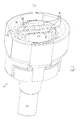
- FIG. 1 shows a perspective view of a connector 1, which is mounted in a housing wall 3 of a device.
- a connector housing 11 of the connector 3 penetrates a substantially congruent to the connector housing 11 opening 5 in the housing 3 of the device.
- the connector 1 can be fastened to the housing wall 3 by at least one fastening means 7, for example at least one screw 7.
- the gap between the connector housing 11 and the housing wall opening 5 can be closed in a fluid-tight and / or dust-tight manner by means of a sealant (not shown).
- the Indian FIG. 1 shown connector 1 is in an initial position, in which closes a closing element 13 at least one contact element receiving opening 15 such that in the interior of the connector 1 arranged contact elements (not shown) are not accessible.
- the closing element 13 preferably closes the at least one contact element receiving opening 15 in a fluid-tight and / or dust-tight manner.
- the fluid-tightness or dust-tightness meets the requirements of the IP64 or IP67 standards.
- the connector housing 11 may include a plurality of contact member receiving openings 15, for example, 2, 3, 4 or more contact member receiving openings 15 separated from each other by a land 11a.
- the at least one web 11a may be formed in particular substantially rectilinear.
- the web 11 a is integrally formed with the connector housing 11.
- FIG. 1 shows a preferred embodiment wherein a plurality of lands 11a are oriented substantially parallel to one another to space a plurality of contact element receiving openings 15 from one another.
- the connector 1 is designed to have a complementary connector (in FIG. 2 shown) along an insertion direction E record.
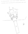
- FIG. 2 shows a perspective view of the complementary connector 9, which is designed at least partially introduced into the interior of the connector 1 along the insertion direction E and contacted with the connector 1.
- the complementary connector 9 has a plurality of complementary contact elements 17 which are adapted to be inserted along the insertion direction E into an associated contact element receiving opening 15 of the connector 1 in order to provide inside the connector 1 an associated contact element (shown in FIGS FIGS. 4 to 8 shown) to contact electrically.
- the complementary contact elements are each arranged on an associated support body 19, which together with the complementary contact elements 17 form-congruent is formed in each case one associated contact element receiving opening 15, so that each of the support body 19 at least partially along the insertion direction E in the associated contact element receiving opening 15 is inserted.
- the support bodies are rigid relative to the complementary contact elements 17 and formed of an electrically non-conductive material.
- the end faces 19a of the support bodies 19 first mechanically contact the closing element 13, which closes off the at least one contact element receiving opening 15.
- a further insertion or displacement of the complementary connector 9 along the insertion direction E causes a pressing force along the insertion direction E to be applied to the closing element 13 via the mechanically rigid support bodies 19 so that the closing element 13 is displaced linearly along the insertion direction E Release contact element receiving openings 15.
- the support bodies 19 and the complementary contact elements 17 disposed thereon are then inserted together through an associated contact element receiving opening 15 in the interior of the connector 1 until the complementary connector 9 and the connector 1 have reached a contacting position in which the complementary connector electrically or mechanically the connector 1 is contacted.
- FIG. 3 shows the complementary connector 9 and the connector 1 in the contacting position.
- the complementary connector 9 may preferably be the part of the connector 1 protruding from the housing wall 3 (in FIG FIG. 1 shown) substantially completely enclose.
- the complementary connector 9 may in particular have a connector receptacle 23 into which the connector 1 can be received, at least in regions, counter to the insertion direction E.
- the wall of the connector receptacle 23 may be formed congruent with a peripheral surface 11 b of the connector housing 11, wherein the wall of the connector receptacle 23 in the contacting position in particular with the peripheral surface 11 b of the connector housing 11 in positive engagement or friction can be reached.
- a predetermined withdrawal force against the insertion direction E must be applied to the complementary connector 9 in order to solve this against the insertion direction E of the connector 1.
- the connection between the wall of the connector receptacle 23 and the peripheral surface 11 b of the connector housing 11 is formed fluid-tight or dust-tight.
- a seal such as an O-ring or a sealing lip may be provided, which is resilient or elastic, to a possibly existing gap between the wall of the connector receptacle 23 and the peripheral surface 11 b of the connector housing 11 against a fluid and / or to seal against dust particles.
- This seal preferably meets the requirements of the IP64 or IP67 standards.
- the peripheral surface 11 b of the connector housing 11 may be formed substantially circular, wherein preferably a chamfer 11 c may be provided so that the complementary connector 9, which has a corresponding complementary chamfer 23 a, can be arranged in only one orientation on the connector 1 , As a result, advantageously contacting the correct associated contact elements of the connector 1 with the associated complementary contact elements 17 of the complementary connector 9 is ensured.
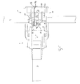
- FIG. 4 shows a sectional view through the connector 1 and the complementary connector 9 separated therefrom in the initial position.
- the connector 1 is arranged in a housing wall opening 5 of a housing wall 3 of an electrical device and secured therein.
- the connector 1 closes the housing wall opening 5 fluid-tight and / or dust-tight.
- the closing member 13 closes the contact member receiving holes 15 of the connector 1 in a fluid-tight and / or dust-proof manner and the connector 1 has no other openings on the user-side side 3a of the housing wall 3 besides the contact member receiving holes 15, the use of the connector 1 as a housing connector allows the Close housing wall opening 5, an improved tightness of the housing against moisture and / or dust particles. This is especially true in the case when no complementary connector 9 is connected to the connector 1.
- the connector 1 includes a contact member receptacle 25 formed in the connector housing 11.
- the contact element receptacle 25 is accessible from the outside through the at least one contact element receiving opening 15, provided that the at least one contact element receiving opening 15 is not closed by the closing element 13.
- At least one electrical contact element 27 is arranged.
- the at least one contact element 27 is mounted or fastened with an end region 27a in a first contact element bearing region 29a.
- the first contact element bearing region is formed in a web 11a of the connector housing 11, wherein the web 11a forms an edge region of the contact element receiving opening 15, which faces the contact element receptacle 25.
- the at least one contact element 27 is mounted with a second end region 27b in a second contact element bearing region 29b.
- the second contact element bearing region can in particular be formed as a continuous bore in the connector housing 11 through which the contact element 27 protrudes.
- one end or tip of the contact element 27 or of the second end region 27b can project through the connector housing 11 in order to be electrically contactable with another element.
- the contact element 27 may in particular be cast or glued in with the second contact element bearing region 29b.
- the at least one second contact element bearing region 29b, to which the at least one contact element 27 is attached, may preferably be formed as a cover 11d or formed in or on a cover 11d, the cover 11d being detachably formed from the remaining connector housing 11 is.
- the at least one contact element 27 is arranged in advance in the second contact element bearing region 29b of the cover 11d and then fixed to then arrange the cover 11d together with the at least one contact element 27 on the connector housing 11, wherein the at least one contact element 27 in the contact element receptacle 25th is introduced so that the first end portion 27a of the contact element 27 is stored in the first contact element bearing portion 29a.
- the first end portion 27a of the at least one contact element 27 is merely inserted into the first contact element bearing region 29a.
- the first contact element bearing region 29a is formed as a blind hole.
- the cover 11d may be attached to the remaining connector housing 11 by means of at least one fastening element 11e, for example at least one screw 11e.
- the closing element 13 is received in a linearly displaceable or displaceable manner along the insertion direction E.
- a closing element 13 is provided precisely, which simultaneously opens or closes the four contact element receiving openings 15 of the connector 1.
- the closing element 13 is displaceable in particular only linearly or translationally within the contact element receptacle 25 relative to the connector housing 11 and can thus in particular not be rotated, rotated or pivoted.
- the contact element receptacle 25 is closed or sealed fluid-tight and / or dust-tight.
- the closing member 13 separates the contact member receptacle 25 (the inside of the connector 1) from the outside of the connector 1 so that no fluid or dust can enter the contact member receptacle 25 from outside through the contact member receiving holes 15. Furthermore, the contact elements 27 are protected from external access by the Contact element receiving openings 15 protected. In other words, the contact elements 27 are arranged in the initial position of the connector 1 in a contact-proof manner in the contact element receptacle 25.
- the closing element 13 may have, for each contact element 27, an associated contact feed-through opening 31 which extends along the insertion direction E. Through the contact passage opening 31 can pass through an associated contact element 27. In particular, the closing element can be moved relative to the contact elements 27 during the displacement along the insertion direction. Like in the FIG. 4 As shown, the at least one contact passing opening 31 of the closing member 13 is arranged in the initial position of the connector 1 in the vicinity of the first end portion 27a of the contact member. By pressing or displacing the closing element 13 along the insertion direction E, the contact feed opening 31 shifts in the direction of the second end region 27b of the contact element 27. Preferably, the contact feedthrough opening 31 is formed with a diameter which ensures mechanical contact between the closing element 13 and the contact element 27 prevented.
- the closing element 13 is formed of an electrically non-conductive material, so that two different contact elements 27 can not be electrically connected by means of the closing element 13.
- the closing element 13 is mechanically biased so that it remains in the initial position without external force.
- the connector may include a biasing element 33 (in FIG FIG. 6 shown), which exerts a force against the insertion direction E on the closing element 13, so that the closing element 13 is pressed against a bearing surface 35 of the connector housing 11.
- the closing element 13 may have a projection 13a which protrudes at least partially through at least one of the at least one contact element receiving openings 15 of the connector 1 in the initial position counter to the insertion direction E.
- a complementary connector 9 may preferably first mechanically contact the closing element 13, in particular in the region of the projection 13a, in order to displace the closing element 13 along the insertion direction E into the contact element receptacle 25.
- the locking element 13 is actuated or displaced merely by the positioning of the complementary connector 9, so that the connector 1 remains in the initial position until the complementary connector 9 is arranged.
- the supporting bodies 19 of the complementary connector 9 can also mechanically contact the closing element 13 and thus apply a force to the closing element 13, which acts along the insertion direction E, so that the closing element 13 is displaced along the insertion direction E. becomes.
- the support bodies 19 are at least partially received by the contact element receiving openings 15 into the contact element receptacle 25, wherein the complementary contact elements 17 are also inserted through the associated contact element receiving openings 15 in the contact element receptacle 25 to electrically contact with the associated contact elements 27 of the connector 1.
- FIG. 5 shows a sectional view through the connector 1 and the complementary connector 9 in the contacting position.
- the FIG. 6 shows a detailed sectional view through the in the FIG. 5 shown connector 1.
- the complementary contact elements 17 are resiliently deformable, so that the complementary contact elements are resiliently displaceable during insertion into the connector 1 along a displacement direction V which is oriented perpendicular to the insertion direction E.
- V which is oriented perpendicular to the insertion direction E.
- the first contact member support portion 29a or the land 11a including the first contact member support portion 29a is made thicker along a thickness direction H oriented perpendicular to the insertion direction E than the contact member 27 mounted in the first contact member support portion 29a the insertion of the complementary connector 9 into the connector 1 becomes each of the complementary contact elements 17, which is inserted along the insertion direction E through the associated contact element receiving opening 15, first mechanically contact the web 11a, so that each complementary contact element 17 at least partially along during the insertion due to the rigidity of the web 11a and the Needlesselementlager Jardins 29a Displacement direction V or along the thickness direction H deformed or displaced.
- the complementary contact elements 17 are bent in such a way that the web 11a or the first contact element bearing region 29a is arranged in the region of a recess 17b of the complementary contact element 17 by further insertion of the contact elements 17 along the insertion direction into the connector 1, one further along the insertion direction E arranged projection 17a of the complementary contact element 17 engages behind the web 11a and the first contact element bearing portion 29a along the thickness direction H and thus can electrically contact the associated contact element 27.
- a pressing force can be applied by the complementary contact element 17, in particular in the region of the projection 17a, to the contact element 27, thereby advantageously minimizing the electrical contact resistance between the complementary contact element 17 and the contact element 27 becomes.
- FIG. 6 shows a coil spring 33 as a preferred biasing element, which is held in a biasing element receiving 13b of the closing element 13.
- the coil spring 33 is supported on the one hand on the closing element 13 and on the other hand on the connector housing 11 and the lid 11 d.
- a mechanical bias is applied to the closing element 13, so that it is pressed counter to the insertion direction E against a bearing surface 35 of the connector housing.
- the connector housing 11 can at least in Area formed in the initial state support surface 35 between the connector housing 11 and the closing element 13 may be formed of an elastomer.
- the end face 13b of the closing element which is pressed in the initial state against the connector housing 11, may be provided with an elastomer layer.
- FIG. 7 shows a perspective view of another embodiment of the connector 1 and the FIG. 8 a sectional view through the in FIG. 7 shown connector 1 and the separate connector 9 separate therefrom FIGS. 7 and 8th embodiment shown correspond substantially to the elements which with reference to the FIGS. 1 to 6 are described, and are therefore denoted by the same reference numerals.
- the connector 1 has a latching means 39 which is adapted to engage with a complementary latching means 41 of the complementary connector 9 when the complementary connector 9 is placed along the insertion direction E on the connector 1.
- the complementary connector 9 can latch with the connector 1 such that release of the complementary connector 9 is made possible either by exceeding a predetermined withdrawal force against the insertion direction E or by actuating an unlocking device.
- the latching device 39 may have a first flank, which is inclined relative to the insertion direction E by an angle ⁇ of about 10 to about 40 °, in particular by about 30 °, so that the complementary latching device 41 when arranging the complementary connector 9 to the connector 1, that is, by a displacement of the latching device 41 along the insertion direction E, along a displacement direction V, which is oriented perpendicular to the insertion direction E, is displaced.
- the at least one latching device 39 has a second flank 39b, which faces the insertion direction E is inclined by an angle ⁇ of about 40 ° to about 60 °, so that the complementary latching device 41 deformed during further displacement along the insertion direction E along the second flank 39b due to the resilience of the complementary latching device 41 against the displacement direction V or is shifted and the locking device 39 engages behind and locked it.
- the edge steepness of the first flank 39a is preferably smaller than the flank steepness of the second flank 39b of the latching device 39, it may be easier or less effort to plug on the complementary connector 9 than pulling off the complementary connector 9.
- the choice of the inclination angle of the first flank or the second edge determines the force to be applied when attaching the complementary connector or when removing the complementary connector. 9
Landscapes
- Connector Housings Or Holding Contact Members (AREA)
Abstract
- ein Verbindergehäuse (11), wobei das Verbindergehäuse (11) eine Kontaktelementaufnahme (25) und zumindest eine Kontaktelementaufnahmeöffnung (15) aufweist,
- zumindest ein elektrisches Kontaktelement (27), welches in der Kontaktelementaufnahme (25) angeordnet ist und welches in zumindest einem Kontaktelementlagerbereich (29a) gelagert ist, wobei der Kontaktelementlagerbereich (29a) in einem der Kontaktelementaufnahme (25) zugewandten Randbereich des Verbindergehäuses (11) um die Kontaktelementaufnahmeöffnung (15) ausgebildet ist, und wobei zumindest ein komplementäres Kontaktelement (17) zumindest bereichsweise entlang einer Einführrichtung (E) durch die Kontaktelementaufnahmeöffnung (15) in die Kontaktelementaufnahme (25) einführbar ist, wodurch ein elektrischer Kontakt zwischen dem zumindest einen Kontaktelement (27) und dem zumindest einen komplementären Kontaktelement (17) herstellbar ist;
- ein Verschließelement (13), welches zumindest bereichsweise in der Kontaktelementaufnahme (25) relativ zum Verbindergehäuse (11) entlang der Einführrichtung (E) verschiebbar angeordnet ist und in einer Initialposition die zumindest eine Kontaktelementaufnahmeöffnung (15) verschließt
sowie eine Verwendung.
Description
- Die Erfindung betrifft einen Verbinder und eine Verwendung des Verbinders.
- In vielen Bereichen der Technik werden elektrische Verbinder benötigt, welche eine feuchtigkeitsdichte und/oder staubdichte Verbindung ermöglichen. Beispielsweise muß bei elektrischen Geräten, die im Feld, in chemischen oder medizinischen Laboratorien, in der Industrie und generell in staubigen und/oder feuchten Umgebungen genutzt werden, verhindert werden, daß Feuchtigkeit und/oder Staub in das Gehäuse des elektrischen Gerätes eindringt. Die elektrischen Geräte werden in der Regel mit Hilfe von Kabeln mit weiteren elektrischen Einrichtungen verbunden. Dazu ist es in den vorgenannten Einsatzgebieten notwendig, auch diese elektrischen Verbindungen feuchtigkeitsdicht und/oder staubdicht auszuführen, um einen sicheren Betrieb zu ermöglichen. Feuchtigkeitsdichte Verbinder sind im allgemeinen bekannt. Beispielsweise sind Verbinder bekannt, welche miteinander verschraubt werden oder mittels eines Bajonettverschlusses miteinander verbunden werden, wobei zumindest ein Dichtring bzw. O-Ring dazu dient, Feuchtigkeit und/oder Staub von den elektrischen Kontakten der miteinander verbundenen Verbinder fernzuhalten.
- Beiden Arten von Verbindern ist gemein, daß das Stecken bzw. die Montage des komplementären Verbinders mit dem Verbinder eine erhöhte Aufmerksamkeit erfordert, um das Schließen des Bajonettverschlusses bzw. der Verschraubung korrekt durchzuführen, und daß der Verbinder durch eine Abdeckung vor dem Eindringen von Staub und Feuchtigkeit geschützt werden muß, wenn der Verbinder nicht mit einem komplementären Verbinder verbunden ist.
- Es ist daher eine Aufgabe, einen Verbinder und eine Verwendung des Verbinders bereitzustellen, um eine vereinfachte Montage bzw. elektrische Verbindung zu ermöglichen.
- Diese Aufgabe wird durch einen Verbinder mit den Merkmalen des Anspruchs 1 und eine Verwendung des Verbinders mit den Merkmalen des Anspruchs 10 gelöst. Bevorzugte Ausführungsformen sind Gegenstand der abhängigen Ansprüche.
- Ein Aspekt der Erfindung betrifft einen Verbinder, der aufweist:
- ein Verbindergehäuse, wobei das Verbindergehäuse eine Kontaktelementaufnahme und zumindest eine Kontaktelementaufnahmeöffnung aufweist,
- zumindest ein elektrisches Kontaktelement, welches in der Kontaktelementaufnahme angeordnet ist und welches in zumindest einem Kontaktelementlagerbereich gelagert ist, wobei der Kontaktelementlagerbereich in einem der Kontaktelementaufnahme zugewandten Randbereich des Verbindergehäuses um die Kontaktelementaufnahmeöffnung ausgebildet ist, und wobei zumindest ein komplementäres Kontaktelement zumindest bereichsweise entlang einer Einführrichtung E durch die Kontaktelementaufnahmeöffnung in die Kontaktelementaufnahme einführbar ist, wodurch ein elektrischer Kontakt zwischen dem zumindest einen Kontaktelement und dem zumindest einen, zugeordneten komplementären Kontaktelement herstellbar ist;
- ein Verschließelement, welches zumindest bereichsweise in der Kontaktelementaufnahme relativ zum Verbindergehäuse entlang der Einführrichtung E verschiebbar angeordnet ist und in einer Initialposition die zumindest eine Kontaktelementaufnahmeöffnung verschließt.
- Vorteilhafterweise wird die Kontaktelementaufnahmeöffnung in der Initialposition durch das Verschließelement verschlossen, so daß die Kontaktelemente vorteilhafterweise in der Initialposition vor äußeren Einflüssen und vor Berührung geschützt sind. Weiter vorteilhafterweise kann das Verschließelement in einfacher Weise durch eine Verlagerung entlang der Einführrichtung E von der Initialposition in eine Kontaktierungsposition überführt werden, in welcher die Kontaktelemente durch zugeordnete komplementäre Kontaktelemente kontaktierbar sind.
- Der Verbinder umfaßt ein Verbindergehäuse, welches bevorzugt aus einem elektrisch nicht leitenden Material besteht. Beispielsweise kann das Verbindergehäuse aus einem Polymer bestehen, beispielsweise aus Polyamid. Das Verbindergehäuse kann einteilig, zweiteilig, dreiteilig oder mehrteilig ausgebildet sein. Insbesondere kann das Verbindergehäuse ausgelegt sein, in einer Öffnung einer Gehäusewandung eines elektrischen Gerätes angeordnet und befestigt zu sein. Bevorzugt kann das Verbindergehäuse im wesentlichen zylindrisch bzw. rotationssymmetrisch ausgebildet sein, um in einer Bohrung durch die Gehäusewandung hindurchgeführt zu werden. Weiter bevorzugt kann das Verbindergehäuse die Öffnung in der Gehäusewandung fluiddicht abschließen, insbesondere feuchtigkeitsdicht und/oder staubdicht abschließen. Der Begriff fluiddicht bzw. staubdicht betrifft insbesondere eine Abdichtung, welche die Anforderungen der Norm IP67 oder IP64 erfüllt. Unter einem Fluid wird sowohl ein Gas, eine Flüssigkeit sowie ein Gemisch davon verstanden.
- In dem Verbindergehäuse ist eine Kontaktelementaufnahme ausgebildet, welche durch das Verbindergehäuse von dem äußeren bzw. der Umgebung des Verbinders getrennt ist. Bevorzugt ist die Kontaktelementaufnahme lediglich durch die zumindest eine Kontaktelementaufnahmeöffnung zugänglich. Die Kontaktelementaufnahmeöffnung ist dabei an der Seite des Verbinders angeordnet, an welche ein komplementärer Verbinder an den Verbinder angeordnet bzw. befestigt werden kann. Für den Fall, daß der Verbinder an einer Gehäusewandung befestigt ist, ist die Kontaktelementaufnahmeöffnung auf der bedienerseitigen Seite der Gehäusewandung angeordnet.
- In der Kontaktelementaufnahme ist zumindest ein elektrisches Kontaktelement angeordnet und in zumindest einem Kontaktelementlagerbereich befestigt. Der dem
- Kontaktelement zugeordnete Kontaktelementlagerbereich ist in einem Randbereich der Kontaktelementaufnahmeöffnung ausgebildet. Der Randbereich der Kontaktelementaufnahmeöffnung kann dabei ein Bereich des Verbindergehäuses sein bzw. einstückig mit dem Verbindergehäuse ausgebildet sein. Alternativ kann der Randbereich der Kontaktelementaufnahmeöffnung ein separates Teil des Verbinders sein, welches mit dem Verbindergehäuse verbunden ist. Da der Kontaktelementlagerbereich an dem der Kontaktelementaufnahme zugewandten Randbereich der Kontaktelementaufnahmeöffnung ausgebildet ist, kann sich ein Kontaktelement, welches in dem Kontaktelementlagerbereich gelagert bzw. befestigt ist, ausgehend von dem Kontaktelementlagerbereich in die Kontaktelementaufnahme, insbesondere entlang der Einführrichtung E, erstrecken. Ein Kontaktelementlagerbereich kann beispielsweise als Ausnehmung bzw. Sackloch ausgebildet sein, in welche(s) ein zugeordnetes Kontaktelement zumindest bereichsweise einführbar ist, um in dem Kontaktelementlagerbereich festgeklemmt, geklebt, verschweißt, vergossen oder anderweitig befestigt zu sein.
- Jedem Kontaktelementlagerbereich kann genau eines des zumindest einen Kontaktelements zugeordnet werden. Der Randbereich jeder der zumindest einen Kontaktelementaufnahmeöffnung kann genau ein, zwei, drei, vier, fünf, oder mehr zugeordnete Kontaktelementlagerbereiche aufweisen. Insbesondere kann der Verbinder genau eine Kontaktelementaufnahmeöffnung aufweisen oder zwei, drei, vier, fünf, sechs oder mehr Kontaktelementeaufnahmeöffnungen.
- Der Verbinder weist ein Verschließelement auf, welches zumindest bereichweise in der Kontaktelementaufnahme angeordnet ist. Das Verschließelement ist relativ zum Verbindergehäuse und damit relativ zur Kontaktelementaufnahmeöffnung entlang der Einführrichtung E verschiebbar. Mit anderen Worten ist das Verschließelement insbesondere lediglich linear bzw. translatorisch verlagerbar und kann somit insbesondere nicht gedreht, rotiert bzw. verschwenkt werden. In der Initialposition verschließt das Verschließelement die zumindest eine Kontaktelementaufnahmeöffnung. Die Initialposition ist dadurch ausgezeichnet, daß der Verbinder in der Initialposition nicht mit einem komplementären Verbinder elektrisch und/oder mechanisch kontaktiert ist. Vielmehr ist die Initialposition des Verbinders bzw. des Verschließelements ein stabiler Zustand bzw. eine stabile Position, in welche der Verbinder bzw. das Verschließelement verharrt oder zurückkehrt, wenn keine äußere Kraft, beispielsweise durch den komplementären Verbinder, auf den Verbinder bzw. das Verschließelement einwirkt. In der Initialposition verschließt das Verschließelement insbesondere alle Kontaktelementaufnahmeöffnungen gleichzeitig. Unter dem Begriff "Verschließen" wird im Sinne der Anmeldung verstanden, daß das Verschließelement die zumindest eine Kontaktelementaufnahmeöffnung berührungssicher, staubdicht, feuchtigkeitsdicht und/oder gasdicht verschließt bzw. versiegelt. Mit anderen Worten ist die Kontaktelementaufnahme in der Initialposition durch das Verschließelement derart vom Äußeren bzw. der Umgebung des Verbinders getrennt, daß ein Benutzer die in der Kontaktelementaufnahme befindlichen Kontaktelemente nicht berühren kann, daß kein Staub mit einer Korngröße kleiner als 1 mm, bevorzugt kleiner als 0,1 mm und insbesondere kleiner als 0,01 mm in die Kontaktelementaufnahme eindringen kann, daß keine Feuchtigkeit im Sinne einer Flüssigkeit, beispielsweise Wasser, und/oder ein Gas, beispielsweise auch Wasserdampf, vom Äußeren des Verbinders in die Kontaktelementaufnahme eindringen kann.
- Das Verschließelement kann bevorzugt ebenfalls aus einem starren Polymer ausgebildet sein. Das Verschließelement kann alternativ auch aus einem Material ausgebildet sein, welches weicher ist, als das Material des Verbindergehäuses, beispielsweise aus einem Elastomer.
- Das Verschließelement kann durch ein Verschieben entlang der Einführrichtung E von der Initialposition in die Kontaktierungsposition überführt werden. Dazu muß eine Kraft entlang der Einführrichtung E an das Verschließelement angelegt werden, um das Verschließelement entlang der Einführrichtung E zu verschieben. Diese Kraft kann beispielsweise durch den komplementären Verbinder an das Verschließelement angelegt werden. Zeitgleich mit oder nach dem Verschieben des Verschließelements von der Initialposition in die Kontaktierungsposition kann zumindest ein komplementäres Kontaktelement des komplementären Verbinders entlang der Einführrichtung E durch eine Zugeordnete der zumindest einen Kontaktelementaufnahmeöffnung in die Kontaktelementaufnahme eingeführt werden, um das zugeordnete Kontaktelement in der Kontaktelementaufnahme elektrisch zu kontaktieren. Vorteilhafterweise wird das Verschließelement erst dann von der Initialposition in die Kontaktierungsposition verlagert, wenn der komplementäre Verbinder an den Verbinder angeordnet und damit kontaktiert wird. Somit wird vorteilhafterweise erreicht, daß der Verbinder berührungssicher, staubdicht, flüssigkeitsdicht und/oder gasdicht abgeschlossen ist, so daß weiter vorteilhafterweise die Kontaktelemente des Verbinders bzw. das Innere eines Gehäuses bzw. Gerätes, für den Fall, daß der Verbinder in einer Gehäusewandung angeordnet ist, vor dem Eindringen von Feuchtigkeit, Staub und ähnlichen schädlichen Einflüssen geschützt ist bzw. sind.
- Vorzugsweise ist der Kontaktelementlagerbereich entlang einer Dickenrichtung H, welche senkrecht zur Einführrichtung E orientiert ist, dicker ausgebildet, als das daran gelagerte Kontaktelement. Mit anderen Worten ist das Kontaktelement entlang der Dickenrichtung H von der zugeordneten Kontaktelementaufnahmeöffnung beabstandet, angeordnet, wobei das Material zwischen dem Kontaktelement und der Kontaktelementaufnahmeöffnung aus einem elektrischen Isolator besteht, welcher den Randbereich der Kontaktelementaufnahmeöffnung ausbildet. Diese geometrische Anordnung hat den Effekt, daß ein komplementäres Kontaktelement, welches entlang der Einführrichtung E in die Kontaktelementaufnahmeöffnung eingeführt wird, entlang der Dickenrichtung H, d.h. senkrecht zur Einführrichtung E, verformt bzw. verlagert werden muß, um das zugeordnete Kontaktelement in der Kontaktelementaufnahme elektrisch zu kontaktieren. Insbesondere ist ein erster Endbereich des Kontaktelements von dem Material des Randbereichs der Kontaktelementaufnahmeöffnung umgeben bzw. umschlossen bzw. fest darin eingeschweißt bzw. eingeschmolzen. Dadurch kann dieser erste Endbereich des Kontaktelements sicher in einer vorbestimmten Position gehalten bzw. fixiert werden. Insbesondere kann in einfacher Weise ein vorbestimmter Abstand zwischen dem Kontaktelement und der zugeordneten Kontaktelementaufnahmeöffnung eingehalten werden. Es versteht sich, daß das Kontaktelement auch an weiteren Punkten bzw. Bereichen fixiert werden kann. Beispielsweise kann das Kontaktelement einen zweiten Endbereich aufweisen, welcher dem ersten Endbereich gegenüberliegt bzw. entgegengesetzt ist, und welcher zumindest bereichsweise durch einen zweiten Kontaktelementlagerbereich fixiert wird.
- Der Kontaktelementlagerbereich kann beispielsweise als Ausnehmung bzw. Sackloch ausgebildet sein, in welche bzw. in welches der erste Endbereich des Kontaktelements zumindest bereichsweise eingeführt ist, um damit verklebt, vergossen, verschweißt, verklemmt oder darin eingeschmolzen zu sein. Insbesondere kann das zumindest eine Kontaktelement bei der Herstellung des Verbinders in einer Spritzgußform bereitgestellt werden, in welcher das Verbindergehäuse einschließlich des Kontaktelementlagerbereichs durch Spritzgießen mit einem Thermoplasten ausgebildet wird. Dadurch kann das Kontaktelement zumindest bereichsweise, insbesondere mit seinem ersten Endbereich von dem Thermoplasten während des Spitzgießens umfangen und eingegossen werden.
- Vorzugsweise weist der Kontaktelementlagerbereich eine Elastomerschicht auf oder ist aus einem Elastomer ausgebildet. Vorteilhafterweise kann ein Elastomer weicher sein, als das im wesentlichen starre Verbindergehäuse. Der Begriff "weicher" beschreibt dabei, daß das Elastizitätsmodul und/oder das Schermodul des Elastomers kleiner ist, als das Elastizitätsmodul und/oder das Schermodul des Verbindergehäuses. Als Elastomer kann zweckmäßigerweise ein thermoplastisches Elastomer (TPE) verwendet werden, wodurch sich die Elastomerschicht, welche den starren Teil des Kontaktelementlagerbereichs zumindest bereichsweise bedeckt, bzw. der Kontaktelementlagerbereich, falls dieser aus dem Elastomer ausgebildet ist, in einfacher Weise, beispielsweise durch Spritzgießen, ausbilden lassen kann. Weiter vorteilhafterweise weisen Elastomere eine verbesserte Dichtwirkung gegenüber Fluiden bzw. gegenüber Staub auf, als das starre Material des Verbindergehäuses.
- Vorzugsweise ist das Verbindergehäuse zumindest im Bereich der im Initialzustand ausgebildeten Auflagefläche zwischen dem Verbindergehäuse und dem Verschließelement aus einem Elastomer ausgebildet. Alternativ oder zusätzlich ist das Verschließelement zumindest im Bereich der im Initialzustand ausgebildeten Auflagefläche zwischen dem Verbindergehäuse und dem Verschließelement aus einem Elastomer ausgebildet. Vorteilhafterweise kann durch das Anordnen eines Elastomers an der Auflagefläche zwischen dem Verbindergehäuse und dem Verschließelement eine verbesserte Dichtwirkung des Verschließelementes erreicht werden, um das Eindringen von Feuchtigkeit und/oder Staub aus der Umgebung des Verbinders in die Kontaktelementaufnahme zu verhindern. Insbesondere genügt schon ein geringer Anpreßdruck zwischen dem Verschließelement und dem Verbindergehäuse, um die Auflagefläche zwischen dem Verschließelement und dem Verbindergehäuse feuchtigkeitsdicht und/oder staubdicht zu halten. Insbesondere kann in einfacher Weise eine Dichtigkeit der Kontaktelementaufnahme bzw. des Verbinders mit den Anforderungen der Norm IP67 erreicht werden.
- Vorzugsweise ist das Verschließelement durch ein Vorspannungselement im Initialzustand gehalten. Mit anderen Worten kann das Vorspannungselement eine Andruckkraft auf das Verschließelement entgegen der Einführrichtung E anlegen, so daß ein vorbestimmter Anpreßdruck zwischen dem Verschließelement und dem Verbindergehäuse aufrechterhalten wird. Dadurch wird die Auflagefläche, an welcher das Verschließelement das Verbindergehäuse mechanisch kontaktiert mit einem vorbestimmten Anpreßdruck beaufschlagt, so daß das Eindringen von Staubpartikeln, beispielsweise mit einer Größe kleiner als 1 mm, bevorzugt kleiner als etwa 100 µm, insbesondere kleiner als etwa 10 µm, und/oder das Eindringen von Flüssigkeiten, wie beispielsweise Wasser, und/oder das Eindringen von Gasen, wie beispielsweise Wasserdampf, gehemmt bzw. verhindert wird.
- Das Vorspannungselement kann zumindest ein rückstellfähiges Element umfassen, welches durch das Anlegen einer äußeren Kraft entlang der Einführrichtung E rückstellfähig verformbar ist, so daß das Vorspannungselement aufgrund seiner Rückstellfähigkeit in seine ursprüngliche Form bzw. Position zurückkehrt, wenn die äußere Kraft nicht mehr wirkt. Dadurch kann in einfacher Weise das Verschließelement, welches mit dem Vorspannungselement verbunden ist, entgegen der Einführrichtung E verlagert bzw. verschoben werden, um die zumindest eine Kontaktelementaufnahmeöffnung zu verschließen. Der Begriff "rückstellfähig" umfaßt insbesondere eine im wesentlichen elastische Verformbarkeit des Vorspannungselements. Beispielsweise kann das Vorspannungselement eine Feder, insbesondere eine Spiralfeder oder eine Blattfeder, einen rückstellfähigen Schaumstoff oder ein sonstiges rückstellfähiges verformbares Element aufweisen.
- Vorzugsweise ist das Verschließelement durch das zumindest bereichsweise Einführen des komplementären Verbinders entlang der Einführrichtung E in die Kontaktelementaufnahme des Verbinders entlang der Einführrichtung E verlagerbar. Insbesondere kann das Verschließelement zumindest bereichsweise durch zumindest eine der zumindest einen Kontaktelementaufnahmeöffnung des Verbinders entgegen der Einführrichtung E hervorragen, so daß der komplementäre Verbinder bevorzugt zuerst das Verschließelement des Verbinders mechanisch kontaktiert, um dieses entlang der Einführrichtung E in die Kontaktelementaufnahme hinein zu verlagern. Vorteilhafterweise wird das Verschließelement erst durch das Anordnen bzw. Kontaktieren eines komplementären Verbinders betätigt bzw. verlagert, so daß sich der Verbinder bis zum Anordnen des komplementären Verbinders in der Initialposition befindet, in weicher der Verbinder bzw. die Kontaktelementaufnahme des Verbinders fluiddicht und/oder staubdicht vom äußeren bzw. der Umgebung des Verbinders verschlossen ist.
- Vorzugsweise weist das Verschließelement zumindest eine durchgehende Kontaktdurchführöffnung auf, durch welche ein zugeordnetes Kontaktelement durchgeführt ist. Insbesondere erstrecken sich die Kontaktdurchführöffnung und das Kontaktelement im wesentlichen entlang der Einführrichtung E so daß das Kontaktelement beim Übergang des Verbinders von der Initialposition in die Kontaktierungsposition relativ zum Verschließelement verlagert wird. Um diese relative Verlagerung zu ermöglichen, kann das zumindest eine Kontaktelement durch die durchgehende Kontaktdurchführöffnung des Verschließelements hindurchgeführt sein bzw. kann das Kontaktelement durch das Verschließelement umfangen sein. Dadurch kann vorteilhafterweise erreicht werden, daß das Verschließelement nicht entlang einer Richtung senkrecht zur Einführrichtung E verlagerbar ist, da sonst ein mechanischer Kontakt zwischen dem zumindest einen Kontaktelement und der Wandung der zugeordneten durchgehenden Kontaktdurchführöffnung eine weitere Verlagerung senkrecht zur Einführrichtung E hemmen würde. Die Kontaktdurchführöffnung kann insbesondere als durchgehende Bohrung durch das Verschließelement ausgebildet sein.
- Vorzugsweise weist der Verbinder eine Rasteinrichtung auf, die durch das Einführen de komplementären Verbinders entlang der Einführrichtung mit einer komplementären Rasteinrichtung verrastbar ist.
- Vorteilhafterweise kann durch ein bloßes Aufstecken des komplementären Verbinders entlang der Einführrichtung E der Verbinder mit dem komplementären Verbinder verrastet werden. Mit anderen Worten bilden der Verbinder bzw. der komplementäre keinen Bajonettverschluß oder Schraubverschluß aus, um den komplementären Verbinder mechanisch an dem Verbinder zu befestigen.
- Wenn der komplementäre Verbinder mit der Rasteinrichtung des Verbinders verrastet, ist ein versehentliches Abziehen des komplementären Verbinders vom Verbinder ausgeschlossen. Ein Lösen des komplementären Verbinders von dem Verbinder kann erst erfolgen, wenn eine vorbestimmte Abzugskraft an dem komplementären Verbinder angelegt wird, um den komplementären Verbinder von dem Verbinder zu lösen bzw. abzuziehen. Insbesondere kann eine Abzugskraft von mehr als etwa 5 N, bevorzugt mehr als etwa 10 N, weiter bevorzugt von mehr als etwa 50 N notwendig sein, um den komplementären Verbinder von dem Verbinder zu lösen. Besonders vorteilhafterweise kann das Verbinden bzw. Lösen des komplementären Verbinders mit bzw. von dem Verbinder einhändig erfolgen, so daß der Benutzer weiter vorteilhafterweise die zweite Hand frei hat, um weitere Tätigkeiten durchzuführen.
- In alternativen Ausführungsbeispielen, d.h. anstelle einer Rasteinrichtung, weist der
- Verbinder ein Gewinde auf. Vorteilhafterweise weist der komplementäre Verbinder ein komplementäres Gewinde auf. Vorzugsweise ist das Gewinde des Verbinders mit dem komplementären Gewinde des komplementären Verbinders verschraubbar. Wenn das Gewinde des Verbinders mit dem komplementären Gewinde des komplementären Verbinders verschraubt ist, ergibt sich der Vorteil, daß ein versehentliches Abziehen des komplementären Verbinders von dem Verbinder ausgeschlossen ist.
- Alternativ kann der Verbinder anstelle des Gewindes auch einen Teil eines Bajonettverschlußes aufweisen. Vorteilhafterweise weist der komplementäre Verbinder einen komplementären Teil eines Bajonettverschlußes auf. Vorzugsweise ist der Teil des Bajonettverschlußes des Verbinders mit dem komplementären Teil des Bajonettverschlußes des komplementären Verbinders verbindbar. Wenn der Teil des Bajonettverschlußes des Verbinders mit dem komplementären Teil des Bajonettverschlußes des komplementären Verbinders verbunden ist, ergibt sich der Vorteil, daß ein versehentliches Abziehen des komplementären Verbinders von dem Verbinder ausgeschlossen ist.
- Alternativ kann der Verbinder anstelle des Gewindes auch einen Teil eines Bügelverschlußes aufweisen. Vorteilhafterweise weist der komplementäre Verbinder einen komplementären Teil eines Bügelverschlußes auf. Vorzugsweise ist der Teil des Bügelverschlußes des Verbinders mit dem komplementären Teil des Bügelverschlußes des komplementären Verbinders verbindbar. Wenn der Teil des Bügelverschluß des Verbinders mit dem komplementären Teil des Bügelverschluß des komplementären Verbinders verbunden ist, ergibt sich der Vorteil, daß ein versehentliches Abziehen des komplementären Verbinders von dem Verbinder ausgeschlossen ist.
- Ein Aspekt der Erfindung betrifft die Verwendung eines erfindungsgemäßen Verbinders als Gehäuseverbinder, wobei der Verbinder fluiddicht in einer Öffnung einer Gehäusewandung angeordnet wird.
- Vorteilhafterweise kann durch die Verwendung des Verbinders als Gehäuseverbinder eine verbesserte Dichtheit des Gehäuses gegenüber Feuchtigkeit und/oder Staubpartikeln erreicht werden. Insbesondere können Feuchtigkeit und/oder Staubpartikel nicht über den Verbinder in das Innere des Gehäuses gelangen, auch wenn der Verbinder nicht mit einem komplementären Verbinder kontaktiert ist. Dabei ist es weiter vorteilhafterweise nicht notwendig, eine Verbinderabdeckung bereitzustellen und bei Nichtnutzung des Verbinders auf diesen aufzusetzen, um den Verbinder bzw. das Gehäuse fluiddicht und/oder staubdicht abzuschließen. Insbesondere kann eine Ausführungsform des Verbinders verwendet werden, welche durch bloßes Aufstecken des komplementären Verbinders entlang der Einführrichtung E auf den Verbinder elektrisch kontaktiert werden kann. Mit anderen Worten weist der Verbinder keinen Bajonettverschluß oder Schraubverschluß auf, um den komplementären Verbinder mechanisch mit dem Verbinder zu kontaktieren bzw. daran zu befestigen. Vielmehr ist es vorteilhaft, wenn der komplementäre Verbinder mit einer Rasteinrichtung des Verbinders verrastet, so daß ein versehentliches Abziehen des komplementären Verbinders vom Verbinder, welcher an dem Gehäuse befestigt ist, vermieden werden kann. Ein Lösen des komplementären Verbinders von dem Verbinder kann vorteilhafterweise erst erfolgen, wenn eine vorbestimmte Abzugskraft an dem komplementären Verbinder angelegt wird, um den komplementären Verbinder von dem Verbinder zu lösen bzw. abzuziehen. Insbesondere kann eine Auszugskraft von mehr als etwa 5 N, bevorzugt mehr als etwa 10 N, weiter bevorzugt von mehr als etwa 50 N notwendig sein, um den komplementären Verbinder von dem Verbinder zu lösen. Besonders vorteilhafterweise kann das Verbinden bzw. Lösen des komplementären Verbinders mit bzw. von dem Verbinder einhändig erfolgen, so daß der Benutzer weiter vorteilhafterweise die zweite Hand frei hat, um weitere Tätigkeiten durchzuführen.
- Nachfolgend werden bevorzugte Ausführungsformen der vorliegenden Erfindung anhand der beigefügten Zeichnungen beispielhaft erläutert, wobei einzelne Merkmale losgelöst voneinander beliebig zu neuen Ausführungsformen kombiniert werden können. Es zeigt:
- Figur 1:
- eine perspektivische Ansicht eines Verbinders, der in einer Gehäusewandung montiert ist, in einer Initialposition;
- Figur 2:
- eine perspektivische Ansicht eines komplementären Verbinders;
- Figur 3:
- eine perspektivische Ansicht einer Anordnung des Verbinders und dem damit kontaktierten komplementäre Verbinder;
- Figur 4:
- eine Schnittansicht durch den Verbinder und den davon getrennten komplementären Verbinder in der Initialposition;
- Figur 5:
- eine Schnittansicht durch den Verbinder in der Kontaktierungsposition und den damit kontaktierten komplementären Verbinder;
- Figur 6:
- eine detaillierte Schnittansicht durch den in
Figur 5 gezeigten Verbinder; - Figur 7:
- eine perspektivische Ansicht einer weiteren Ausführungsform des Verbinders;
- Figur 8:
- eine Schnittansicht durch den in
Figur 7 gezeigten Verbinder und den davon getrennten komplementären Verbinder. - Die
Figur 1 zeigt eine perspektivische Ansicht eines Verbinders 1, der in einer Gehäusewandung 3 eines Gerätes montiert ist. Dabei durchdringt ein Verbindergehäuse 11 des Verbinders 3 eine im wesentlichen zum Verbindergehäuse 11 formkongruente Öffnung 5 in der Gehäusewandung 3 des Gerätes. Der Verbinder 1 kann durch zumindest ein Befestigungsmittel 7, beispielsweise zumindest einer Schraube 7, an der Gehäusewandung 3 befestigt sein. Der Spalt zwischen dem Verbindergehäuse 11 und der Gehäusewandungsöffnung 5 kann mittels eines Dichtmittels (nicht gezeigt) fluiddicht und/oder staubdicht verschlossen sein. - Der in der
Figur 1 gezeigte Verbinder 1 befindet sich in einer Initialposition, in welcher ein Verschließelement 13 zumindest eine Kontaktelementaufnahmeöffnung 15 derart verschließt, daß im Inneren des Verbinders 1 angeordnete Kontaktelemente (nicht gezeigt) nicht zugänglich sind. Bevorzugt verschließt das Verschließelement 13 die zumindest eine Kontaktelementaufnahmeöffnung 15 fluiddicht und/oder staubdicht. Insbesondere genügt die Fluiddichtigkeit bzw. Staubdichtigkeit den Anforderungen der Normen IP64 oder IP67. - Wie in
Figur 1 gezeigt, kann das Verbindergehäuse 11 eine Vielzahl von Kontaktelementaufnahmeöffnungen 15, beispielsweise 2, 3, 4 oder mehr Kontaktelementaufnahmeöffnungen 15, aufweisen, welche voneinander durch einen Steg 11a getrennt sind. Der zumindest eine Steg 11a kann insbesondere im wesentlichen geradlinig ausgebildet sein. Bevorzugt ist der Steg 11 a einstückig mit dem Verbindergehäuse 11 ausgebildet. DieFigur 1 zeigt eine bevorzugte Ausführungsform, wobei eine Vielzahl von Stegen 11a im wesentlichen parallel zueinander orientiert sind, um eine Vielzahl von Kontaktelementaufnahmeöffnungen 15 voneinander zu beabstanden. - Der Verbinder 1 ist ausgelegt, einen komplementären Verbinder (in
Figur 2 gezeigt) entlang einer Einführrichtung E aufzunehmen. - Die
Figur 2 zeigt eine perspektivische Ansicht des komplementären Verbinders 9, welcher ausgelegt ist zumindest bereichsweise in das Innere des Verbinders 1 entlang der Einführrichtung E eingeführt und mit dem Verbinder 1 kontaktiert zu werden. - Der komplementäre Verbinder 9 weist eine Vielzahl von komplementären Kontaktelementen 17 auf, welche ausgelegt sind entlang der Einführrichtung E in eine zugeordnete Kontaktelementaufnahmeöffnung 15 des Verbinders 1 eingeführt zu werden, um im Inneren des Verbinders 1 ein zugeordnetes Kontaktelement (in den
Figuren 4 bis 8 gezeigt) elektrisch zu kontaktieren. Die komplementären Kontaktelemente sind jeweils an einem zugeordneten Stützkörper 19 angeordnet, welcher zusammen mit dem komplementären Kontaktelementen 17 formkongruent zu jeweils einer zugeordneten Kontaktelementaufnahmeöffnung 15 ausgebildet ist, so daß jeder der Stützkörper 19 zumindest bereichsweise entlang der Einführrichtung E in die zugeordnete Kontaktelementaufnahmeöffnung 15 einführbar ist. Die Stützkörper sind relativ zu den komplementären Kontaktelementen 17 starr und aus einem elektrisch nicht leitenden Material ausgebildet. Beim Einführen des komplementären Verbinders 9 in den Verbinder 1 kontaktieren die Stirnflächen 19a der Stützkörper 19 zunächst mechanisch das Verschließelement 13, welches die zumindest eine Kontaktelementaufnahmeöffnung 15 verschließt. Über die mechanisch starren Stützkörper 19 kann durch ein weiteres Einführen bzw. Verlagern des komplementären Verbinders 9 entlang der Einführrichtung E eine Andruckkraft entlang der Einführrichtung E an das Verschließelement 13 angelegt werden, so daß das Verschließelement 13 entlang der Einführrichtung E linear verlagert wird, um die Kontaktelementaufnahmeöffnungen 15 freizugeben. Die Stützkörper 19 und die daran angeordneten komplementären Kontaktelemente 17 werden dann gemeinsam durch eine zugeordnete Kontaktelementaufnahmeöffnung 15 in das Innere des Verbinders 1 eingeführt, bis der komplementäre Verbinder 9 und der Verbinder 1 eine Kontaktierungsposition erreicht haben, in welcher der komplementäre Verbinder elektrisch bzw. mechanisch mit dem Verbinder 1 kontaktiert ist. - Die
Figur 3 zeigt den komplementären Verbinder 9 und den Verbinder 1 in der Kontaktierungsposition. Mittels eines Anschlußkabels 21, welches an dem komplementären Verbinder 9 angebracht ist, kann das Gerät elektrisch mit weiteren Geräten verbunden werden. In der Kontaktierungsposition kann der komplementäre Verbinder 9 bevorzugt den aus der Gehäusewandung 3 vorstehenden Teil des Verbinders 1 (inFigur 1 gezeigt) im wesentlichen vollständig umschließen. Dazu kann der komplementäre Verbinder 9 insbesondere eine Verbinderaufnahme 23 aufweisen, in welche der Verbinder 1 zumindest bereichsweise entgegen der Einführrichtung E aufnehmbar ist. Die Wandung der Verbinderaufnahme 23 kann formkongruent zu einer Umfangsfläche 11 b des Verbindergehäuses 11 ausgebildet sein, wobei die Wandung der Verbinderaufnahme 23 in der Kontaktierungsposition insbesondere mit der Umfangsfläche 11 b des Verbindergehäuses 11 in Formschluß bzw. Reibschluß gelangt sein kann. Durch diesen Formschluß bzw. Reibschluß kann erreicht werden, daß eine vorbestimmte Abzugskraft entgegen der Einführrichtung E an den komplementären Verbinder 9 angelegt werden muß, um diesen entgegen der Einführrichtung E von dem Verbinder 1 zu lösen. Besonders bevorzugt ist die Verbindung zwischen der Wandung der Verbinderaufnahme 23 und der Umfangsfläche 11 b des Verbindergehäuses 11 fluiddicht bzw. staubdicht ausgebildet. Dazu kann insbesondere eine Dichtung, wie beispielsweise ein O-Ring oder eine Dichtlippe vorgesehen sein, welche rückstellfähig bzw. elastisch ausgebildet ist, um einen möglicherweise vorhandenen Spalt zwischen der Wandung der Verbinderaufnahme 23 und der Umfangsfläche 11 b des Verbindergehäuses 11 gegenüber einem Fluid und/oder gegenüber Staubpartikeln abzudichten. Diese Abdichtung erfüllt bevorzugt die Anforderungen der Normen IP64 oder IP67. - Die Umfangsfläche 11 b des Verbindergehäuses 11 kann im wesentlichen kreisförmig ausgebildet sein, wobei bevorzugt eine Fase 11 c vorgesehen sein kann, so daß der komplementäre Verbinder 9, welcher eine entsprechende komplementäre Fase 23a aufweist, in lediglich einer Orientierung an dem Verbinder 1 angeordnet werden kann. Dadurch ist vorteilhafterweise das Kontaktieren der richtigen zugeordneten Kontaktelemente des Verbinders 1 mit den zugehörigen komplementären Kontaktelementen 17 des komplementären Verbinders 9 gewährleistet.
-
Figur 4 zeigt eine Schnittansicht durch den Verbinder 1 und den davon getrennten komplementären Verbinder 9 in der Initialposition. Der Verbinder 1 ist in einer Gehäusewandungsöffnung 5 einer Gehäusewandung 3 eines elektrischen Gerätes angeordnet und darin befestigt. Dabei verschließt der Verbinder 1 die Gehäusewandungsöffnung 5 fluiddicht und/oder staubdicht. Da in der Initialposition das Verschließelement 13 die Kontaktelementaufnahmeöffnungen 15 des Verbinders 1 fluiddicht und/oder staubdicht verschließt und der Verbinder 1 neben den Kontaktelementaufnahmeöffnungen 15 keine weiteren Öffnungen auf der benutzerseitigen Seite 3a der Gehäusewandung 3 aufweist, ermöglicht die Verwendung des Verbinders 1 als Gehäuseverbinder, um die Gehäusewandungsöffnung 5 zu verschließen, eine verbesserte Dichtheit des Gehäuses gegenüber Feuchtigkeit und/oder Staubpartikeln. Dies gilt insbesondere für den Fall, wenn kein komplementärer Verbinder 9 an dem Verbinder 1 angeschlossen ist. - Der Verbinder 1 umfaßt eine Kontaktelementaufnahme 25, welche im Verbindergehäuse 11 ausgebildet ist. Die Kontaktelementaufnahme 25 ist durch die zumindest eine Kontaktelementaufnahmeöffnung 15 von außen zugänglich, sofern die zumindest eine Kontaktelementaufnahmeöffnung 15 nicht durch das Verschließelement 13 verschlossen ist.
- In der Kontaktelementaufnahme 25 ist zumindest ein elektrisches Kontaktelement 27 angeordnet. Das zumindest eine Kontaktelement 27 ist mit einem Endbereich 27a in einem ersten Kontaktelementlagerbereich 29a gelagert bzw. darin befestigt. In der in
Figur 4 gezeigten Ausführungsform ist der erste Kontaktelementlagerbereich in einem Steg 11a des Verbindergehäuses 11 ausgebildet, wobei der Steg 11a einen Randbereich der Kontaktelementaufnahmeöffnung 15 ausbildet, welche der Kontaktelementaufnahme 25 zugewandt ist. Das zumindest eine Kontaktelement 27 ist mit einem zweiten Endbereich 27b in einem zweiten Kontaktelementlagerbereich 29b gelagert. Der zweite Kontaktelementlagerbereich kann insbesondere als eine durchgängige Bohrung in dem Verbindergehäuse 11 ausgebildet sein durch welche das Kontaktelement 27 hindurchragt. Insbesondere kann eine Ende bzw. eine Spitze des Kontaktelements 27 bzw. des zweiten Endbereichs 27b durch das Verbindergehäuse 11 hindurchragen, um elektrisch mit einem weiteren Element kontaktierbar zu sein. Das Kontaktelement 27 kann insbesondere mit dem zweiten Kontaktelementlagerbereich 29b vergossen bzw. darin eingeklebt sein. Der zumindest eine zweite Kontaktelementlagerbereich 29b, an welchem das zumindest eine Kontaktelement 27 befestigt ist, kann bevorzugt als ein Deckel 11 d ausgebildet sein bzw. in oder an einem Deckel 11 d ausgebildet sein, wobei der Deckel 11 d von dem restlichen Verbindergehäuse 11 lösbar ausgebildet ist. Durch den Deckel 11 d kann insbesondere eine weitere Öffnung verschlossen sein, durch welche die Kontaktelementaufnahme 25 zugänglich ist. Zum Ausbilden des Verbinders 1 kann insbesondere das zumindest eine Kontaktelement 27 im voraus im zweiten Kontaktelementlagerbereich 29b des Deckels 11d angeordnet bzw. darin befestigt werden, um dann den Deckel 11d zusammen mit dem zumindest einen Kontaktelement 27 an dem Verbindergehäuse 11 anzuordnen, wobei das zumindest eine Kontaktelement 27 in die Kontaktelementaufnahme 25 derart eingeführt wird, das der erste Endbereich 27a des Kontaktelements 27 in dem ersten Kontaktelementlagerbereich 29a gelagert wird. Bevorzugt wird der erste Endbereich 27a des zumindest einen Kontaktelements 27 lediglich in den ersten Kontaktelementlagerbereich 29a eingeschoben. Weiter bevorzugt ist der erste Kontaktelementlagerbereich 29a als ein Sackloch ausgebildet. Der Deckel 11 d kann beispielsweise mittels zumindest einem Befestigungselement 11 e, beispielsweise zumindest einer Schraube 11e an dem restlichen Verbindergehäuse 11 befestigt sein. - In der Kontaktelementaufnahme 25 ist das Verschließelement 13 entlang der Einführrichtung E linear verschiebbar bzw. verlagerbar aufgenommen. In der in
Figur 4 gezeigten bevorzugten Ausführungsform des Verbinders 1 ist genau ein Verschließelement 13 vorgesehen, welches die vier Kontaktelementaufnahmeöffnungen 15 des Verbinders 1 gleichzeitig öffnet bzw. schließt. Das Verschließelement 13 ist insbesondere lediglich linear bzw. translatorisch innerhalb der Kontaktelementaufnahme 25 relativ zum Verbindergehäuse 11 verschiebbar und kann somit insbesondere nicht gedreht, rotiert bzw. geschwenkt werden. In der inFigur 4 gezeigten Initialposition verschließt das Verschließelement 13 die Kontaktelementaufnahmeöffnungen 15. Durch das Verschließen der Kontaktelementaufnahmeöffnungen 15 des Verbinders 1 durch das Verschließelement 13 ist die Kontaktelementaufnahme 25 fluiddicht und/oder staubdicht verschlossen bzw. versiegelt. Mit anderen Worten trennt das Verschließelement 13 die Kontaktelementaufnahme 25 (das Innere des Verbinders 1) vom Äußeren des Verbinders 1 derart, daß kein Fluid bzw. kein Staub in die Kontaktelementaufnahme 25 von außen durch die Kontaktelementaufnahmeöffnungen 15 eindringen kann. Des Weiteren sind die Kontaktelemente 27 vor einem Zugriff von außen durch die Kontaktelementaufnahmeöffnungen 15 geschützt. Mit anderen Worten sind die Kontaktelemente 27 in der Initialposition des Verbinders 1 berührungssicher in der Kontaktelementaufnahme 25 angeordnet. - Das Verschließelement 13 kann zu jedem Kontaktelement 27 eine zugeordnete Kontaktdurchführöffnung 31 aufweisen, welche sich entlang der Einführrichtung E erstreckt. Durch die Kontaktdurchführöffnung 31 kann ein zugeordnetes Kontaktelement 27 durchgreifen. Insbesondere kann das Verschließelement beim Verlagern entlang der Einführrichtung relativ zu dem Kontaktelementen 27 bewegt werden. Wie in der
Figur 4 gezeigt, ist die zumindest eine Kontaktdurchführöffnung 31 des Verschließelementes 13 in der Initialposition des Verbinders 1 in der Nähe des ersten Endbereichs 27a des Kontaktelements angeordnet. Durch ein Betätigen bzw. Verlagern des Verschließelementes 13 entlang der Einführrichtung E verschiebt sich die Kontaktdurchführöffnung 31 in Richtung des zweiten Endbereichs 27b des Kontaktelements 27. Bevorzugt ist die Kontaktdurchführöffnung 31 mit einem Durchmesser ausgebildet, der einen mechanischen Kontakt zwischen dem Verschließelement 13 und dem Kontaktelement 27 verhindert. Zweckmäßigerweise ist das Verschließelement 13 aus einem elektrisch nicht leitfähigen Material ausgebildet, so daß zwei verschiedene Kontaktelemente 27 nicht mittels des Verschließelementes 13 elektrisch verbunden werden können. Das Verschließelement 13 wird mechanisch derart vorgespannt, daß es ohne äußere Krafteinwirkung in der Initialposition verharrt. Dazu kann der Verbinder ein Vorspannungselement 33 (inFigur 6 gezeigt) aufweisen, welches eine Kraft entgegen der Einführrichtung E auf das Verschließelement 13 ausübt, so daß das Verschließelement 13 gegen eine Auflagefläche 35 des Verbindergehäuses 11 gepreßt wird. - Das Verschließelement 13 kann einen Vorsprung 13a aufweisen, welcher zumindest bereichsweise durch zumindest eine der zumindest einen Kontaktelementaufnahmeöffnungen 15 des Verbinders 1 in der Initialposition entgegen der Einführrichtung E hervorragt.
- Ein komplementärer Verbinder 9 kann bevorzugt zuerst das Verschließelement 13 insbesondere im Bereich des Vorsprungs 13a, mechanisch kontaktiert, um das Verschließelement 13 entlang der Einführrichtung E in die Kontaktelementaufnahme 25 hinein zu verlagern. Vorteilhafterweise wird das Verschließelement 13 lediglich durch das Anordnen des komplementären Verbinders 9 betätigt bzw. verlagert, so daß der Verbinder 1 bis zu Anordnen des komplementären Verbinders 9 in der Initialposition verbleibt. Durch das Anordnen des komplementären Verbinders 9 können auch die Stützkörper 19 des komplementären Verbinders 9 mit dem Verschließelements 13 mechanisch kontaktieren und somit eine Kraft auf das Verschließelement 13, welche entlang der Einführrichtung E wirkt, anlegen, so daß das Verschließelement 13 entlang der Einführrichtung E verlagert wird. Dabei werden die Stützkörper 19 zumindest bereichsweise durch die Kontaktelementaufnahmeöffnungen 15 hindurch in die Kontaktelementaufnahme 25 aufgenommen, wobei die komplementären Kontaktelemente 17 ebenfalls durch die zugeordneten Kontaktelementaufnahmeöffnungen 15 in die Kontaktelementaufnahme 25 eingeführt werden, um mit den zugeordneten Kontaktelementen 27 des Verbinders 1 elektrisch zu kontaktieren.
- Die
Figur 5 zeigt eine Schnittansicht durch den Verbinder 1 und den komplementären Verbinder 9 in der Kontaktierungsposition. DieFigur 6 zeigt eine detaillierte Schnittansicht durch den in derFigur 5 gezeigten Verbinder 1. - Wie insbesondere in der
Figur 6 gezeigt, sind die komplementären Kontaktelemente 17 rückstellfähig verformbar ausgebildet, so daß die komplementären Kontaktelemente während des Einführens in den Verbinder 1 entlang einer Verlagerungsrichtung V, welche senkrecht zur Einführrichtung E orientiert ist, rückstellfähig verlagerbar sind. Wie in derFigur 6 gezeigt, ist der erste Kontaktelementlagerbereich 29a bzw. der Steg 11a, welche dem ersten Kontaktelementlagerbereich 29a umfassen, entlang einer Dickenrichtung H, welche senkrecht zur Einführrichtung E orientiert ist, dicker bzw. mächtiger ausgebildet, als das im ersten Kontaktelementlagerbereich 29a gelagerte Kontaktelement 27. Während des Einführens des komplementären Verbinders 9 in den Verbinder 1 wird jedes der komplementären Kontaktelemente 17, welches entlang der Einführrichtung E durch die zugeordnete Kontaktelementaufnahmeöffnung 15 eingeführt wird, zunächst den Steg 11a mechanisch kontaktieren, so daß jedes komplementäre Kontaktelement 17 während des Einführens aufgrund der Starrheit des Stegs 11a bzw. des Kontaktselementlagerbereichs 29a zumindest bereichsweise entlang der Verlagerungsrichtung V bzw. entlang der Dickenrichtung H verformt bzw. verlagert wird. Die komplementären Kontaktelemente 17 sind derart gebogen, daß durch das weitere Einführen der Kontaktelemente 17 entlang der Einführrichtung in den Verbinder 1 der Steg 11a bzw. der erste Kontaktelementlagerbereich 29a im Bereich eines Rücksprungs 17b des komplementären Kontaktelements 17 angeordnet ist, wobei ein weiter entlang der Einführrichtung E angeordneter Vorsprung 17a des komplementären Kontaktelements 17 den Steg 11a bzw. den ersten Kontaktelementlagerbereich 29a entlang der Dickenrichtung H hintergreift und somit das zugeordnete Kontaktelement 27 elektrisch kontaktieren kann. Insbesondere kann aufgrund der rückstellfähigen bzw. elastischen Verformbarkeit des komplementären Kontaktelements 17 eine Andruckkraft durch das komplementäre Kontaktelement 17, insbesondere im Bereich des Vorsprungs 17a, auf das Kontaktelement 27 angelegt werden, wodurch vorteilhafterweise der elektrische Übergangswiderstand zwischen dem komplementären Kontaktelement 17 und dem Kontaktelement 27 minimiert wird. Vorteilhafterweise ist es somit nicht möglich durch das bloße Einführen eines geraden Gegenstandes oder Kontakts in die Kontaktelementaufnahmeöffnung 15 eines der Kontaktelemente 27 elektrisch zu kontaktieren. Dadurch wird vorteilhafterweise ein erhöhter Berührungsschutz der Kontaktelemente 27 erreicht. -
Figur 6 zeigt eine Spiralfeder 33 als bevorzugtes Vorspannungselement, welche in einer Vorspannungselementaufnahme 13b des Verschließelements 13 gehalten ist. Die Spiralfeder 33 stützt sich zum einen an dem Verschließelement 13 und zum anderen an dem Verbindergehäuse 11 bzw. dem Deckel 11 d ab. Dadurch wird eine mechanische Vorspannung an das Verschließelement 13 angelegt, so daß dieses entgegen der Einführrichtung E gegen eine Auflagefläche 35 des Verbindergehäuses gepreßt wird. Das Verbindergehäuse 11 kann zumindest im Bereich der im Initialzustand ausgebildeten Auflagefläche 35 zwischen dem Verbindergehäuse 11 und dem Verschließelement 13 aus einem Elastomer ausgebildet sein. Beispielsweise kann eine Schicht 37 aus einem Elastomer an dem Verbindergehäuse 11 bzw. an den Stegen 11a, insbesondere im Bereich des ersten Kontaktelementlagerbereichs 29a angeordnet bzw. ausgebildet sein, so daß das Verschließelement 13 gegen die Elastomerschicht 37 gepreßt wird, wodurch sich eine verbesserte Dichtwirkung des Verschießelements erzielen läßt. Es versteht sich, daß alternativ oder zusätzlich die Stirnfläche 13b des Verschließelements, welche im Initialzustand gegen das Verbindergehäuse 11 gepreßt wird, mit einer Elastomerschicht versehen sein kann. - Die
Figur 7 zeigt eine perspektivische Ansicht einer weiteren Ausführungsform des Verbinders 1 und dieFigur 8 eine Schnittansicht durch den inFigur 7 gezeigten Verbinder 1 und den davon getrennten komplementären Verbinder 9. Die einzelnen Elemente der in denFiguren 7 und8 gezeigten Ausführungsform entsprechen im wesentlichen den Elementen, welche mit Bezug auf dieFiguren 1 bis 6 beschrieben sind, und sind daher mit den gleichen Bezugszeichen gekennzeichnet. Zusätzlich weist der Verbinder 1 eine Rasteinrichtung 39 auf, welche ausgelegt ist mit einer komplementären Rasteinrichtung 41 des komplementären Verbinders 9 in Eingriff zu gelangen, wenn der komplementäre Verbinder 9 entlang der Einführrichtung E an dem Verbinder 1 angeordnet wird. Durch die Rasteinrichtung kann der komplementäre Verbinder 9 mit dem Verbinder 1 derart verrasten, daß ein Lösen des komplementären Verbinders 9 entweder durch Überschreiten einer vorbestimmten Abzugskraft entgegen der Einführrichtung E oder durch Betätigen einer Entriegelungsvorrichtung ermöglicht wird. Die Rasteinrichtung 39 kann eine erste Flanke aufweisen, welche gegenüber der Einführrichtung E um einen Winkel α von etwa 10 bis etwa 40°, insbesondere um etwa 30°, geneigt ist, so daß die komplementäre Rasteinrichtung 41 beim Anordnen des komplementären Verbinders 9 an den Verbinder 1, das heißt durch eine Verlagerung der Rasteinrichtung 41 entlang der Einführrichtung E, entlang einer Verlagerungsrichtung V, welche senkrecht zur Einführrichtung E orientiert ist, verlagert wird. Weiter weist die zumindest eine Rasteinrichtung 39 eine zweite Flanke 39b auf, welche gegenüber der Einführrichtung E um einen Winkel β von etwa 40° bis etwa 60° geneigt ist, so daß die komplementäre Rasteinrichtung 41 beim weiteren Verlagern entlang der Einführrichtung E entlang der zweiten Flanke 39b aufgrund der Rückstellfähigkeit der komplementären Rasteinrichtung 41 entgegen der Verlagerungsrichtung V verformt bzw. verlagert wird und die Rasteinrichtung 39 hintergreift und damit verrastet. Da die Flankensteilheit der ersten Flanke 39a bevorzugt kleiner ist als die Flankensteilheit der zweiten Flanke 39b der Rasteinrichtung 39 kann ein Aufstecken des komplementären Verbinders 9 vorzugsweise leichter bzw. mit geringerem Kraftaufwand erfolgen als ein Abziehen des komplementären Verbinders 9. Die Wahl der Neigungswinkel der ersten Flanke bzw. der zweiten Flanke bestimmt dabei die aufzuwendende Kraft beim Aufstecken des komplementären Verbinders bzw. beim Abziehen des komplementären Verbinders 9. -
- 1
- Verbinder
- 3
- Gehäusewandung
- 5
- Gehäusewandungsöffnung der Gehäusewandung 3
- 7
- Befestigungsmittel
- 9
- komplementärer Verbinder
- 11
- Verbindergehäuse
- 11a
- Steg des Verbindergehäuses 11
- 11b
- Umfangsfläche des Verbindergehäuses 11
- 11c
- Fase
- 11d
- Deckel
- 11e
- Befestigungsmittel
- 13
- Verschließelement
- 13a
- Vorsprung
- 13b
- Vorspannungselementaufnahme
- 15
- Kontaktelementaufnahmeöffnung
- 17
- komplementäre Kontaktelemente
- 19
- Stützkörper
- 19a
- Stirnfläche des Stützkörpers 19
- 21
- Anschlußkabel
- 23
- Verbinderaufnahme
- 23a
- komplementäre Fase
- 25
- Kontaktelementaufnahme
- 27
- elektrisches Kontaktelement
- 27a
- erster Endbereich des elektrischen Kontaktelements 27
- 27b
- zweiter Endbereich des elektrischen Kontaktelements 27
- 29a
- erster Kontaktelementlagerbereich
- 29b
- zweiter Kontaktelementlagerbereich
- 31
- Kontaktdurchführöffnung
- 33
- Vorspannungselement
- 35
- Auflagefläche
- 37
- Elastomerschicht
- 39
- Rasteinrichtung
- 41
- komplementäre Rasteinrichtung
- E
- Einführrichtung
- H
- Dickenrichtung
- V
- Verlagerungsrichtung
Claims (10)
- Verbinder (1) aufweisend:- ein Verbindergehäuse (11), wobei das Verbindergehäuse (11) eine Kontaktelementaufnahme (25) und zumindest eine Kontaktelementaufnahmeöffnung (15) aufweist,- zumindest ein elektrisches Kontaktelement (27), welches in der Kontaktelementaufnahme (25) angeordnet ist und welches in zumindest einem Kontaktelementlagerbereich (29a) gelagert ist, wobei der Kontaktelementlagerbereich (29a) in einem der Kontaktelementaufnahme (25) zugewandten Randbereich des Verbindergehäuses (11) um die Kontaktelementaufnahmeöffnung (15) ausgebildet ist, und wobei zumindest ein komplementäres Kontaktelement (17) zumindest bereichsweise entlang einer Einführrichtung (E) durch die Kontaktelementaufnahmeöffnung (15) in die Kontaktelementaufnahme (25) einführbar ist, wodurch ein elektrischer Kontakt zwischen dem zumindest einen Kontaktelement (27) und dem zumindest einen komplementären Kontaktelement (17) herstellbar ist;- ein Verschließelement (13), welches zumindest bereichsweise in der Kontaktelementaufnahme (25) relativ zum Verbindergehäuse (11) entlang der Einführrichtung (E) verschiebbar angeordnet ist und in einer Initialposition die zumindest eine Kontaktelementaufnahmeöffnung (15) verschließt.
- Verbinder (1) gemäß Anspruch 1, wobei der Kontaktelementlagerbereich (29a) entlang einer Dickenrichtung (H), welche senkrecht zur Einführrichtung (E) orientiert ist, dicker ausgebildet ist, als das daran gelagerte Kontaktelement (27).
- Verbinder (1) gemäß Anspruch 1 oder 2, wobei der Kontaktelementlagerbereich (29a) aus einem Elastomer ausgebildet ist oder eine Elastomerschicht (35) aufweist.
- Verbinder (1) gemäß einem der vorigen Ansprüche, wobei das Verbindergehäuse (11) und/oder das Verschließelement (13) zumindest im Bereich der im Initialzustand ausgebildeten Auflagefläche zwischen dem Verbindergehäuse (11) und dem Verschließelement (13) aus einem Elastomer ausgebildet ist oder sind.
- Verbinder (1) gemäß einem der vorigen Ansprüche, wobei das Verschließelement (13) durch ein Vorspannungselement (33) im Initialzustand gehalten ist.
- Verbinder (1) gemäß einem der vorigen Ansprüche, wobei das Verschließelement (13) durch das zumindest bereichsweise Einführen eines komplementären Verbinders (9) entlang der Einführrichtung (E) in die Kontaktelementaufnahme (25) des Verbinders (1) entlang der Einführrichtung (E) verlagerbar ist.
- Verbinder (1) gemäß einem der vorigen Ansprüche, wobei das Verschließelement (13) zumindest bereichsweise entgegen der Einführrichtung (E) aus der Kontaktelementaufnahmeöffnung (15) vorragt.
- Verbinder (1) gemäß einem der vorigen Ansprüche, wobei das Verschließelement (13) zumindest eine durchgehende Kontaktdurchführöffnung (31) aufweist, durch welche ein zugeordnetes des zumindest einen Kontaktelements (27) durchgeführt ist.
- Verbinder (1) gemäß einem der vorigen Ansprüche, wobei der Verbinder eine Rasteinrichtung (39) aufweist, die durch das Einführen der komplementären Verbinders (9) entlang der Einführrichtung (E) mit einer komplementären Rasteinrichtung (41) verrastbar ist.
- Verwendung eines Verbinders (1) gemäß einem der vorigen Ansprüche als Gehäuseverbinder, wobei der Verbinder (1) fluiddicht in einer Gehäusewandungsöffnung (5) einer Gehäusewandung (3) angeordnet wird.
Applications Claiming Priority (1)
| Application Number | Priority Date | Filing Date | Title |
|---|---|---|---|
| DE201310003685 DE102013003685B4 (de) | 2013-03-04 | 2013-03-04 | Verbinder und Verwendung |
Publications (2)
| Publication Number | Publication Date |
|---|---|
| EP2775569A1 true EP2775569A1 (de) | 2014-09-10 |
| EP2775569B1 EP2775569B1 (de) | 2020-04-15 |
Family
ID=50235872
Family Applications (1)
| Application Number | Title | Priority Date | Filing Date |
|---|---|---|---|
| EP14000771.7A Active EP2775569B1 (de) | 2013-03-04 | 2014-03-04 | Verbinder und Verwendung |
Country Status (2)
| Country | Link |
|---|---|
| EP (1) | EP2775569B1 (de) |
| DE (1) | DE102013003685B4 (de) |
Citations (4)
| Publication number | Priority date | Publication date | Assignee | Title |
|---|---|---|---|---|
| DE19809801A1 (de) * | 1998-03-09 | 1999-09-16 | Kromberg & Schubert | Elektrische Kontaktvorrichtung, insbesondere für Fahrzeuge |
| FR2884363A1 (fr) * | 2005-04-11 | 2006-10-13 | Valeo Electronique Sys Liaison | Connecteur electrique |
| US20070212918A1 (en) * | 2006-03-10 | 2007-09-13 | Edwin Gruebel | Socket/plug coupling unit |
| US20100240231A1 (en) * | 2009-03-19 | 2010-09-23 | Fujitsu Limited | Connector and device including the same |
Family Cites Families (3)
| Publication number | Priority date | Publication date | Assignee | Title |
|---|---|---|---|---|
| DE10142196A1 (de) * | 2001-08-29 | 2003-03-20 | Harting Automotive Gmbh & Co | Buchse für eine schmutzgeschützte Steckverbindung sowie Steckverbindung |
| JP4181895B2 (ja) * | 2003-02-25 | 2008-11-19 | 日本圧着端子製造株式会社 | リセプタクル |
| DE202009004604U1 (de) * | 2009-03-06 | 2009-06-10 | Franz Binder Gmbh + Co. Elektrische Bauelemente Kg | Steckverbinder |
-
2013
- 2013-03-04 DE DE201310003685 patent/DE102013003685B4/de active Active
-
2014
- 2014-03-04 EP EP14000771.7A patent/EP2775569B1/de active Active
Patent Citations (4)
| Publication number | Priority date | Publication date | Assignee | Title |
|---|---|---|---|---|
| DE19809801A1 (de) * | 1998-03-09 | 1999-09-16 | Kromberg & Schubert | Elektrische Kontaktvorrichtung, insbesondere für Fahrzeuge |
| FR2884363A1 (fr) * | 2005-04-11 | 2006-10-13 | Valeo Electronique Sys Liaison | Connecteur electrique |
| US20070212918A1 (en) * | 2006-03-10 | 2007-09-13 | Edwin Gruebel | Socket/plug coupling unit |
| US20100240231A1 (en) * | 2009-03-19 | 2010-09-23 | Fujitsu Limited | Connector and device including the same |
Also Published As
| Publication number | Publication date |
|---|---|
| EP2775569B1 (de) | 2020-04-15 |
| DE102013003685B4 (de) | 2015-04-23 |
| DE102013003685A1 (de) | 2014-09-04 |
Similar Documents
| Publication | Publication Date | Title |
|---|---|---|
| WO2015150048A1 (de) | Connector position assurance (cpa) und steckverbinderanordnung mit einer cpa | |
| EP3057183B1 (de) | Gedichteter Stecker | |
| DE1098565B (de) | Elektrische loesbare Steckvorrichtung fuer elektrische Durchfuehrungen | |
| DE102004030666A1 (de) | Gehäuse zur Aufnahme elektrischer und/oder elektronischer Bauteile | |
| EP2249448A2 (de) | Kabeldurchführung | |
| DE202014103822U1 (de) | Verschlusskappe für ein Sensorgehäuse und Sensorset | |
| DE112017005162B4 (de) | Durchgangsverbinderanordnung | |
| DE102010013446A1 (de) | Steckerelement mit Verriegelungsabdichtung | |
| DE102008047145B3 (de) | Vorrichtung zum Verschließen und zum Öffnen einer Steckverbinder-Durchführung | |
| DE102015203489A1 (de) | Elektrischer Steckverbinder mit Kabelklemmeinrichtung | |
| EP2551978B1 (de) | Vorrichtung zur Durchführung einer elektrischen Leitung durch ein Gehäuse | |
| EP3871295A1 (de) | Elektrischer Stecker, elektrisches Gerät, elektrische Steckverbindung und Verfahren zur Herstellung eines elektrischen Geräts | |
| DE102015102696B3 (de) | Abgedichtetes Gehäuse zur Aufnahme eines elektronischen Bauelements, insbesondere eines Relais, Bauelement mit einem derartigen Gehäuse sowie Verfahren zu dessen Erzeugung | |
| DE102016217456B3 (de) | Anordnung für einen elektrischen Steckverbinder sowie Steckverbinder mit einem Kontaktgehäuse, Umgehäuse und Sicherungselement | |
| DE19942921C2 (de) | Steckverbinder, insbesondere Winkelsteckverbinder | |
| DE4433617C2 (de) | Elektrisches Steckverbindungsteil | |
| EP0818853A2 (de) | Zündpillen-Steckverbindung | |
| DE19846576C2 (de) | Plombierbare Verschließeinrichtung | |
| DE102013003685B4 (de) | Verbinder und Verwendung | |
| DE102019206287B4 (de) | Verschließvorrichtung | |
| DE69306620T2 (de) | Steckdose und elektrische Kupplungsvorrichtung | |
| DE4224155C2 (de) | Elektrische Steckverbinderanordnung | |
| DE102007037283B4 (de) | Kontaktsystem mit einer Kabelaufnahmevorrichtung und mit einem Kabel | |
| LU102227B1 (de) | Steckdose mit einem Aktuator zur Führung eines Verriegelungselements | |
| EP3895254B1 (de) | Steckverbinderteil zur kontaktierung in mehreren raumrichtungen |
Legal Events
| Date | Code | Title | Description |
|---|---|---|---|
| PUAI | Public reference made under article 153(3) epc to a published international application that has entered the european phase |
Free format text: ORIGINAL CODE: 0009012 |
|
| 17P | Request for examination filed |
Effective date: 20140304 |
|
| AK | Designated contracting states |
Kind code of ref document: A1 Designated state(s): AL AT BE BG CH CY CZ DE DK EE ES FI FR GB GR HR HU IE IS IT LI LT LU LV MC MK MT NL NO PL PT RO RS SE SI SK SM TR |
|
| AX | Request for extension of the european patent |
Extension state: BA ME |
|
| R17P | Request for examination filed (corrected) |
Effective date: 20150305 |
|
| RBV | Designated contracting states (corrected) |
Designated state(s): AL AT BE BG CH CY CZ DE DK EE ES FI FR GB GR HR HU IE IS IT LI LT LU LV MC MK MT NL NO PL PT RO RS SE SI SK SM TR |
|
| STAA | Information on the status of an ep patent application or granted ep patent |
Free format text: STATUS: EXAMINATION IS IN PROGRESS |
|
| 17Q | First examination report despatched |
Effective date: 20170721 |
|
| GRAP | Despatch of communication of intention to grant a patent |
Free format text: ORIGINAL CODE: EPIDOSNIGR1 |
|
| STAA | Information on the status of an ep patent application or granted ep patent |
Free format text: STATUS: GRANT OF PATENT IS INTENDED |
|
| INTG | Intention to grant announced |
Effective date: 20191127 |
|
| GRAS | Grant fee paid |
Free format text: ORIGINAL CODE: EPIDOSNIGR3 |
|
| GRAA | (expected) grant |
Free format text: ORIGINAL CODE: 0009210 |
|
| STAA | Information on the status of an ep patent application or granted ep patent |
Free format text: STATUS: THE PATENT HAS BEEN GRANTED |
|
| AK | Designated contracting states |
Kind code of ref document: B1 Designated state(s): AL AT BE BG CH CY CZ DE DK EE ES FI FR GB GR HR HU IE IS IT LI LT LU LV MC MK MT NL NO PL PT RO RS SE SI SK SM TR |
|
| REG | Reference to a national code |
Ref country code: CH Ref legal event code: EP |
|
| REG | Reference to a national code |
Ref country code: DE Ref legal event code: R096 Ref document number: 502014013964 Country of ref document: DE |
|
| REG | Reference to a national code |
Ref country code: IE Ref legal event code: FG4D Free format text: LANGUAGE OF EP DOCUMENT: GERMAN |
|
| REG | Reference to a national code |
Ref country code: AT Ref legal event code: REF Ref document number: 1258386 Country of ref document: AT Kind code of ref document: T Effective date: 20200515 |
|
| REG | Reference to a national code |
Ref country code: NL Ref legal event code: MP Effective date: 20200415 |
|
| REG | Reference to a national code |
Ref country code: LT Ref legal event code: MG4D |
|
| PG25 | Lapsed in a contracting state [announced via postgrant information from national office to epo] |
Ref country code: FI Free format text: LAPSE BECAUSE OF FAILURE TO SUBMIT A TRANSLATION OF THE DESCRIPTION OR TO PAY THE FEE WITHIN THE PRESCRIBED TIME-LIMIT Effective date: 20200415 Ref country code: NO Free format text: LAPSE BECAUSE OF FAILURE TO SUBMIT A TRANSLATION OF THE DESCRIPTION OR TO PAY THE FEE WITHIN THE PRESCRIBED TIME-LIMIT Effective date: 20200715 Ref country code: GR Free format text: LAPSE BECAUSE OF FAILURE TO SUBMIT A TRANSLATION OF THE DESCRIPTION OR TO PAY THE FEE WITHIN THE PRESCRIBED TIME-LIMIT Effective date: 20200716 Ref country code: SE Free format text: LAPSE BECAUSE OF FAILURE TO SUBMIT A TRANSLATION OF THE DESCRIPTION OR TO PAY THE FEE WITHIN THE PRESCRIBED TIME-LIMIT Effective date: 20200415 Ref country code: IS Free format text: LAPSE BECAUSE OF FAILURE TO SUBMIT A TRANSLATION OF THE DESCRIPTION OR TO PAY THE FEE WITHIN THE PRESCRIBED TIME-LIMIT Effective date: 20200815 Ref country code: LT Free format text: LAPSE BECAUSE OF FAILURE TO SUBMIT A TRANSLATION OF THE DESCRIPTION OR TO PAY THE FEE WITHIN THE PRESCRIBED TIME-LIMIT Effective date: 20200415 Ref country code: NL Free format text: LAPSE BECAUSE OF FAILURE TO SUBMIT A TRANSLATION OF THE DESCRIPTION OR TO PAY THE FEE WITHIN THE PRESCRIBED TIME-LIMIT Effective date: 20200415 Ref country code: PT Free format text: LAPSE BECAUSE OF FAILURE TO SUBMIT A TRANSLATION OF THE DESCRIPTION OR TO PAY THE FEE WITHIN THE PRESCRIBED TIME-LIMIT Effective date: 20200817 |
|
| PG25 | Lapsed in a contracting state [announced via postgrant information from national office to epo] |
Ref country code: BG Free format text: LAPSE BECAUSE OF FAILURE TO SUBMIT A TRANSLATION OF THE DESCRIPTION OR TO PAY THE FEE WITHIN THE PRESCRIBED TIME-LIMIT Effective date: 20200715 Ref country code: LV Free format text: LAPSE BECAUSE OF FAILURE TO SUBMIT A TRANSLATION OF THE DESCRIPTION OR TO PAY THE FEE WITHIN THE PRESCRIBED TIME-LIMIT Effective date: 20200415 Ref country code: RS Free format text: LAPSE BECAUSE OF FAILURE TO SUBMIT A TRANSLATION OF THE DESCRIPTION OR TO PAY THE FEE WITHIN THE PRESCRIBED TIME-LIMIT Effective date: 20200415 Ref country code: HR Free format text: LAPSE BECAUSE OF FAILURE TO SUBMIT A TRANSLATION OF THE DESCRIPTION OR TO PAY THE FEE WITHIN THE PRESCRIBED TIME-LIMIT Effective date: 20200415 |
|
| PG25 | Lapsed in a contracting state [announced via postgrant information from national office to epo] |
Ref country code: AL Free format text: LAPSE BECAUSE OF FAILURE TO SUBMIT A TRANSLATION OF THE DESCRIPTION OR TO PAY THE FEE WITHIN THE PRESCRIBED TIME-LIMIT Effective date: 20200415 |
|
| REG | Reference to a national code |
Ref country code: DE Ref legal event code: R097 Ref document number: 502014013964 Country of ref document: DE |
|
| PG25 | Lapsed in a contracting state [announced via postgrant information from national office to epo] |
Ref country code: DK Free format text: LAPSE BECAUSE OF FAILURE TO SUBMIT A TRANSLATION OF THE DESCRIPTION OR TO PAY THE FEE WITHIN THE PRESCRIBED TIME-LIMIT Effective date: 20200415 Ref country code: SM Free format text: LAPSE BECAUSE OF FAILURE TO SUBMIT A TRANSLATION OF THE DESCRIPTION OR TO PAY THE FEE WITHIN THE PRESCRIBED TIME-LIMIT Effective date: 20200415 Ref country code: EE Free format text: LAPSE BECAUSE OF FAILURE TO SUBMIT A TRANSLATION OF THE DESCRIPTION OR TO PAY THE FEE WITHIN THE PRESCRIBED TIME-LIMIT Effective date: 20200415 Ref country code: IT Free format text: LAPSE BECAUSE OF FAILURE TO SUBMIT A TRANSLATION OF THE DESCRIPTION OR TO PAY THE FEE WITHIN THE PRESCRIBED TIME-LIMIT Effective date: 20200415 Ref country code: ES Free format text: LAPSE BECAUSE OF FAILURE TO SUBMIT A TRANSLATION OF THE DESCRIPTION OR TO PAY THE FEE WITHIN THE PRESCRIBED TIME-LIMIT Effective date: 20200415 Ref country code: RO Free format text: LAPSE BECAUSE OF FAILURE TO SUBMIT A TRANSLATION OF THE DESCRIPTION OR TO PAY THE FEE WITHIN THE PRESCRIBED TIME-LIMIT Effective date: 20200415 Ref country code: CZ Free format text: LAPSE BECAUSE OF FAILURE TO SUBMIT A TRANSLATION OF THE DESCRIPTION OR TO PAY THE FEE WITHIN THE PRESCRIBED TIME-LIMIT Effective date: 20200415 |
|
| PLBE | No opposition filed within time limit |
Free format text: ORIGINAL CODE: 0009261 |
|
| STAA | Information on the status of an ep patent application or granted ep patent |
Free format text: STATUS: NO OPPOSITION FILED WITHIN TIME LIMIT |
|
| PG25 | Lapsed in a contracting state [announced via postgrant information from national office to epo] |
Ref country code: PL Free format text: LAPSE BECAUSE OF FAILURE TO SUBMIT A TRANSLATION OF THE DESCRIPTION OR TO PAY THE FEE WITHIN THE PRESCRIBED TIME-LIMIT Effective date: 20200415 Ref country code: SK Free format text: LAPSE BECAUSE OF FAILURE TO SUBMIT A TRANSLATION OF THE DESCRIPTION OR TO PAY THE FEE WITHIN THE PRESCRIBED TIME-LIMIT Effective date: 20200415 |
|
| 26N | No opposition filed |
Effective date: 20210118 |
|
| PG25 | Lapsed in a contracting state [announced via postgrant information from national office to epo] |
Ref country code: SI Free format text: LAPSE BECAUSE OF FAILURE TO SUBMIT A TRANSLATION OF THE DESCRIPTION OR TO PAY THE FEE WITHIN THE PRESCRIBED TIME-LIMIT Effective date: 20200415 |
|
| PG25 | Lapsed in a contracting state [announced via postgrant information from national office to epo] |
Ref country code: MC Free format text: LAPSE BECAUSE OF FAILURE TO SUBMIT A TRANSLATION OF THE DESCRIPTION OR TO PAY THE FEE WITHIN THE PRESCRIBED TIME-LIMIT Effective date: 20200415 |
|
| REG | Reference to a national code |
Ref country code: CH Ref legal event code: PL |
|
| REG | Reference to a national code |
Ref country code: BE Ref legal event code: MM Effective date: 20210331 |
|
| PG25 | Lapsed in a contracting state [announced via postgrant information from national office to epo] |
Ref country code: IE Free format text: LAPSE BECAUSE OF NON-PAYMENT OF DUE FEES Effective date: 20210304 Ref country code: CH Free format text: LAPSE BECAUSE OF NON-PAYMENT OF DUE FEES Effective date: 20210331 Ref country code: LU Free format text: LAPSE BECAUSE OF NON-PAYMENT OF DUE FEES Effective date: 20210304 Ref country code: LI Free format text: LAPSE BECAUSE OF NON-PAYMENT OF DUE FEES Effective date: 20210331 |
|
| REG | Reference to a national code |
Ref country code: AT Ref legal event code: MM01 Ref document number: 1258386 Country of ref document: AT Kind code of ref document: T Effective date: 20210304 |
|
| PG25 | Lapsed in a contracting state [announced via postgrant information from national office to epo] |
Ref country code: BE Free format text: LAPSE BECAUSE OF NON-PAYMENT OF DUE FEES Effective date: 20210331 |
|
| PG25 | Lapsed in a contracting state [announced via postgrant information from national office to epo] |
Ref country code: AT Free format text: LAPSE BECAUSE OF NON-PAYMENT OF DUE FEES Effective date: 20210304 |
|
| PG25 | Lapsed in a contracting state [announced via postgrant information from national office to epo] |
Ref country code: HU Free format text: LAPSE BECAUSE OF FAILURE TO SUBMIT A TRANSLATION OF THE DESCRIPTION OR TO PAY THE FEE WITHIN THE PRESCRIBED TIME-LIMIT; INVALID AB INITIO Effective date: 20140304 |
|
| PG25 | Lapsed in a contracting state [announced via postgrant information from national office to epo] |
Ref country code: CY Free format text: LAPSE BECAUSE OF FAILURE TO SUBMIT A TRANSLATION OF THE DESCRIPTION OR TO PAY THE FEE WITHIN THE PRESCRIBED TIME-LIMIT Effective date: 20200415 |
|
| PG25 | Lapsed in a contracting state [announced via postgrant information from national office to epo] |
Ref country code: MK Free format text: LAPSE BECAUSE OF FAILURE TO SUBMIT A TRANSLATION OF THE DESCRIPTION OR TO PAY THE FEE WITHIN THE PRESCRIBED TIME-LIMIT Effective date: 20200415 |
|
| PG25 | Lapsed in a contracting state [announced via postgrant information from national office to epo] |
Ref country code: TR Free format text: LAPSE BECAUSE OF FAILURE TO SUBMIT A TRANSLATION OF THE DESCRIPTION OR TO PAY THE FEE WITHIN THE PRESCRIBED TIME-LIMIT Effective date: 20200415 |
|
| PG25 | Lapsed in a contracting state [announced via postgrant information from national office to epo] |
Ref country code: MT Free format text: LAPSE BECAUSE OF FAILURE TO SUBMIT A TRANSLATION OF THE DESCRIPTION OR TO PAY THE FEE WITHIN THE PRESCRIBED TIME-LIMIT Effective date: 20200415 |
|
| PGFP | Annual fee paid to national office [announced via postgrant information from national office to epo] |
Ref country code: GB Payment date: 20260326 Year of fee payment: 13 |
|
| PGFP | Annual fee paid to national office [announced via postgrant information from national office to epo] |
Ref country code: DE Payment date: 20260326 Year of fee payment: 13 |
|
| PGFP | Annual fee paid to national office [announced via postgrant information from national office to epo] |
Ref country code: FR Payment date: 20260326 Year of fee payment: 13 |