EP2774847B1 - Abnehmbare Rotorschaufelspitze - Google Patents
Abnehmbare Rotorschaufelspitze Download PDFInfo
- Publication number
- EP2774847B1 EP2774847B1 EP13165390.9A EP13165390A EP2774847B1 EP 2774847 B1 EP2774847 B1 EP 2774847B1 EP 13165390 A EP13165390 A EP 13165390A EP 2774847 B1 EP2774847 B1 EP 2774847B1
- Authority
- EP
- European Patent Office
- Prior art keywords
- connector
- anchor
- root
- rotor blade
- axis
- Prior art date
- Legal status (The legal status is an assumption and is not a legal conclusion. Google has not performed a legal analysis and makes no representation as to the accuracy of the status listed.)
- Active
Links
Images


Classifications
-
- F—MECHANICAL ENGINEERING; LIGHTING; HEATING; WEAPONS; BLASTING
- F01—MACHINES OR ENGINES IN GENERAL; ENGINE PLANTS IN GENERAL; STEAM ENGINES
- F01D—NON-POSITIVE DISPLACEMENT MACHINES OR ENGINES, e.g. STEAM TURBINES
- F01D5/00—Blades; Blade-carrying members; Heating, heat-insulating, cooling or antivibration means on the blades or the members
- F01D5/12—Blades
- F01D5/14—Form or construction
- F01D5/147—Construction, i.e. structural features, e.g. of weight-saving hollow blades
-
- B—PERFORMING OPERATIONS; TRANSPORTING
- B64—AIRCRAFT; AVIATION; COSMONAUTICS
- B64C—AEROPLANES; HELICOPTERS
- B64C27/00—Rotorcraft; Rotors peculiar thereto
- B64C27/32—Rotors
- B64C27/46—Blades
- B64C27/463—Blade tips
-
- Y—GENERAL TAGGING OF NEW TECHNOLOGICAL DEVELOPMENTS; GENERAL TAGGING OF CROSS-SECTIONAL TECHNOLOGIES SPANNING OVER SEVERAL SECTIONS OF THE IPC; TECHNICAL SUBJECTS COVERED BY FORMER USPC CROSS-REFERENCE ART COLLECTIONS [XRACs] AND DIGESTS
- Y10—TECHNICAL SUBJECTS COVERED BY FORMER USPC
- Y10T—TECHNICAL SUBJECTS COVERED BY FORMER US CLASSIFICATION
- Y10T29/00—Metal working
- Y10T29/49—Method of mechanical manufacture
- Y10T29/49316—Impeller making
- Y10T29/49336—Blade making
- Y10T29/49337—Composite blade
Definitions
- Rotor blades such as, but not limited to, rotor blades for helicopters, may comprise tips configured to manage tip noise and/or to increase performance.
- a rotor blade tip may be damaged or otherwise may be undesirable for a selected application while a root of the same rotor blade may be acceptable for the selected application.
- DE638559 discloses a rotor blade comprising a wing that is subdivided into sections. The angle of the distal section of the wing is adjustable.
- the invention concerns a notor blade accodring to claim 1 and a method assembling a rotor blade according to claim 2.
- a rotor system comprising an axis of rotation and a rotor blade comprising a spanwise axis and configured for selective rotation about the axis of rotation, the rotor blade further comprising a root comprising an anchor, and a selectively removable tip comprising a connector configured to complement the anchor, wherein the root is at least partially disposed along the spanwise axis between the tip and the axis of rotation, and wherein having a connector surface configured to generally complement the anchor surface, and mating the connector surface to the anchor surface.
- a rotor system comprising an axis of rotation and a rotor blade comprising a spanwise axis and configured for selective rotation about the axis of rotation, the rotor blade further comprising a root comprising an anchor, and a selectively removable tip comprising a connector configured to complement the anchor, wherein the root is at least partially disposed along the spanwise axis between the tip and the axis of rotation, and wherein at least a portion of the connector is located along the spanwise axis between the axis of rotation and the anchor.
- a rotor blade tip such as, but not limited to, a tip of a helicopter rotor blade.
- a rotor blade tip such as, but not limited to, a tip of a helicopter rotor blade.
- a rotor blade tip it may be desirable to replace the tip while retaining the root of the rotor blade.
- systems and methods comprise providing a rotor blade with a selectively removable tip, wherein a substantial and/or primary centrifugal force generated by rotating the rotor blade about an axis of rotation is transferred between an anchor of a root of the rotor blade and a connector of the tip of the rotor blade.
- the centrifugal force may be transferred substantially directly between the anchor and the connector without substantially passing through and/or otherwise relying on a transfer path that comprises bolts.
- the transfer of the centrifugal force may be accomplished by locating at least a portion of the connector between the center of rotation and the anchor.
- an integrity of a connection between the root and the tip may be increased with an increase in the centrifugal force and/or increased rate of rotation of the rotor blade about the axis of rotation.
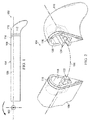
- the rotor system 100 generally comprises an axis of rotation 102 (see Figure 1 ) that may be associated with a rotating mast and/or hub and one or more rotor blades 104.
- the rotor blade 104 generally comprises a spanwise axis 106 that may generally extend along a length of the rotor blade 104 and may generally be associated with a centrifugal force generated in response to the rotor blade 104 being rotated about the axis of rotation 102.
- the rotor blade 104 further comprises a root 108 and a selectively removable tip 110 connected at a distal end of the root 108.
- a joint and/or mating interface 112 between the exteriors of the root 108 and tip 110 may be overlaid by a doubler patch 114 (see Figure 1 ) that may comprise directional fiber composite material adhered to slightly recessed shelves 116 (see Figure 2 ) of the root 108 and tip 110 so that the exterior surfaces of the root 108 and tip 110 may more closely behave at least one of structurally and aerodynamically as if the two were integrally formed.
- a doubler patch 114 may simply overlay outer surfaces of the root 108 and tip 110 without filling a shelf 116.
- the tip 110 may comprise an anhedral shape configured to reduce tip noise and/or to otherwise improve performance of the rotor blade 104.
- the rotor blade 104 further comprises a root cavity 118 and may comprise a tip cavity 120.
- the root cavity 118 may comprise a pocket or concavity formed in a distal end of the root 108.
- at least a portion of an anchor 122 may be disposed in the root cavity 118.
- the anchor 122 may comprise a substantially rigid component embedded, anchored, integrally formed with, adhered to, and/or otherwise substantially rigidly spatially retained relative to a remainder of the root 108 and/or relative to the boundaries of the root cavity 118.
- the anchor 122 may be referred to as a spar.
- the tip cavity 120 may comprise a pocket or concavity formed in a proximal end of the tip 110.
- at least a portion of a connector 124 may be disposed in the tip cavity 120.
- the connector 124 may comprise a substantially rigid component embedded, anchored, integrally formed with, adhered to, and/or otherwise at least partially substantially rigidly spatially retained relative to a remainder of the tip 110 and/or relative to the boundaries of the tip cavity 120.
- the connector 124 may be referred to as a spar extension.
- the rotor blade 104, root 108, tip 110, root cavity 118, tip cavity 120, anchor 122, and connector 124 may comprise a base set of generalized features and/or components upon which the additional details, features, and/or embodiments of Figures 3-8 may utilize and/or build upon.
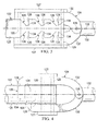
- the anchor 122 may generally comprise a cantilevered root rod 125 comprising teeth-shaped recesses 126.
- the recesses may comprise anchor surfaces 128 that lie generally normal to the spanwise axis 106.
- the connector 124 may generally comprise a cantilevered tip rod 130 to which one or more side jaws 132 are movably connected via a jaw pin 135.
- Side jaws 132 may comprise teeth 134 complementarily shaped to substantially fill the recesses 126 of root rod 125.
- any substantial centrifugal force tending to pull the tip 110 away from the root 108 may be transferred from the teeth 134 of the side jaws 132 to the anchor surfaces 128 of the recesses 126. Because the anchor surfaces 128 are generally normal to the spanwise axis 106, the side jaws 132 will not tend to open away from the root rod 125. In alternative embodiments, the anchor surfaces 128 may be acutely angled relative to the spanwise axis 106 which may cause the complementary teeth 134 to more securely engage the anchor surfaces 128 with an increase in centrifugal force. In some embodiments, the side jaws 132 may be biased toward each other about jaw pin 135 through the use of a spring and/or any other suitable mechanical biasing device.
- the side jaws 132 may be at least one of biased toward each other and/or spatially restrained relative to the root rod 125 by disposing a plug 127, spacer, shim, epoxy, and/or any other suitably stiff and/or expansive material between the side jaws 132 and adjacent interior walls of the root cavity 118 and/or tip cavity 120.
- interior walls of the root cavity 118 and/or tip cavity 120 may be angled to selectively cause a closing action of the side jaws 132 toward the root rod 125 as the connector 124 is inserted into the root cavity 118.
- the connector 124 may be inserted into the root cavity 118 through a distal end of the root cavity 118.
- the connector 124 may be placed into position relative to the root rod 125 before a top or bottom wall of the root cavity 118 is fully formed so that the connector 124 slides into place relative to the root rod 125 like a puzzle piece from above or below. After such placement, a remainder of the root cavity 118 and/or tip cavity 120 may be completed to form the rotor blade 104.
- a hoop stress component 129 may be applied generally at least partially circumferentially around at least a portion of each of the anchor 122 and the complementary connector 124 to maintain the connection between the anchor 122 and a complementary connector 124.
- the hoop stress component 129 may be installed in a relatively low load direction and may assist in ensuring a centrifugal force capacity of the system and may reduce fretting and/or cyclical and/or fatigue working of the connection. In some cases, the hoop stress component 129 may be configured to additionally extend around the plug 127. In some embodiments, the hoop stress component 129 may comprise epoxy, an elastic and/or elastomeric material, a metallic strap, a shrink wrap component, and/or any other suitable strap or loop configured to retain the system components relative to each other.
- the anchor 122 may generally comprise a cantilevered root rod 125 comprising box-shaped recesses 126.
- the recesses may comprise anchor surfaces 128 that lie generally normal to the spanwise axis 106.
- the connector 124 may generally comprise a cantilevered tip rod 130 to which one or more side jaws 132 are movably connected via a jaw pin 135.
- Side jaws 132 may comprise teeth 134 complementarily shaped to substantially fill the recesses 126 of root rod 125.
- any substantial centrifugal force tending to pull the tip 110 away from the root 108 may be transferred from the teeth 134 of the side jaws 132 to the anchor surfaces 128 of the recesses 126. Because the anchor surfaces 128 are generally normal to the spanwise axis 106, the side jaws 132 will not tend to open away from the root rod 125. In alternative embodiments, the anchor surfaces 128 may be acutely angled relative to the spanwise axis 106 which may cause the complementary teeth 134 to more securely engage the anchor surfaces 128 with an increase in centrifugal force. In some embodiments, the side jaws 132 may be biased toward each other about jaw pin 135 through the use of a spring and/or any other suitable mechanical biasing device.
- the side jaws 132 may be at least one of biased toward each other and/or spatially restrained relative to the root rod 125 by disposing a plug 127, spacer, shim, epoxy, and/or any other suitably stiff and/or expansive material between the side jaws 132 and adjacent interior walls of the root cavity 118 and/or tip cavity 120.
- interior walls of the root cavity 118 and/or tip cavity 120 may be angled to selectively cause a closing action of the side jaws 132 toward the root rod 125 as the connector 124 is inserted into the root cavity 118.
- the connector 124 may be inserted into the root cavity 118 through a distal end of the root cavity 118.
- the connector 124 may be placed into position relative to the root rod 125 before a top or bottom wall of the root cavity 118 is fully formed so that the connector 124 slides into place relative to the root rod 125 like a puzzle piece from above or below. After such placement, a remainder of the root cavity 118 and/or tip cavity 120 may be completed to form the rotor blade 104.
- the recesses 126 and associated teeth 134 may overlap each other spanwise and/or chordwise (transverse to spanwise) as viewed from above and/or spanwise and/or chordwise as viewed from a side so that recesses 126 and teeth 134 may be disposed at various locations on root rod 125 while preserving a needed cross-sectional area of material for transmitting centrifugal forces.
- the anchor 122 may generally comprise a cantilevered root rod 125 comprising a generally annular recess 126.
- the recess 126 may comprise a concave anchor surface 128 that generally faces open toward the axis of rotation 102.
- the connector 124 may generally comprise a cantilevered tip rod to which one or more side jaws 132 are movably connected via a jaw pin.
- Side jaws 132 may comprise teeth 134 complementarily shaped to substantially fill the recess 126 of root rod 125, including the concavity formed by the anchor surface 128.
- any substantial centrifugal force tending to pull the tip 110 away from the root 108 may be transferred from the teeth 134 of the side jaws 132 to the anchor surface 128 of the recess 126. Because the anchor surface 128 is concave and the teeth 134 are convex, at least on a distal side, the side jaws 132 will not tend to open away from the root rod 125.
- the anchor surfaces 128 may be acutely angled relative to the spanwise axis 106 which may cause the complementary teeth 134 to more securely engage the anchor surfaces 128 with an increase in centrifugal force.
- the side jaws 132 may be biased toward each other about a jaw pin through the use of a spring and/or any other suitable mechanical biasing device. Additionally and/or alternatively, the side jaws 132 may be at least one of biased toward each other and/or spatially restrained relative to the root rod 125 by disposing a plug 127, spacer, shim, epoxy, and/or any other suitably stiff and/or expansive material between the side jaws 132 and adjacent interior walls of the root cavity 118 and/or tip cavity 120. In some embodiments, interior walls of the root cavity 118 and/or tip cavity 120 may be angled to selectively cause a closing action of the side jaws 132 toward the root rod 125 as the connector 124 is inserted into the root cavity 118.
- the connector 124 may be inserted into the root cavity 118 through a distal end of the root cavity 118. However, in alternative embodiments, the connector 124 may be placed into position relative to the root rod 125 before a wall of the root cavity 118 is fully formed. After such placement, a remainder of the root cavity 118 and/or tip cavity 120 may be completed to form the rotor blade 104.
- an orthogonal top view of an anchor 122 and a complementary connector 124 are shown in an assembled state according to another embodiment of the disclosure.
- the anchor 122 is substantially similar to the anchor 122 of Figure 3 but for the shape of the recesses 126.
- the connector 124 is substantially similar to the connector 124 of Figure 3 but for the side jaws 132 not being substantially hinged. Instead, the teeth 134 are individually biased toward the recesses 126 of the anchor 122.
- Recesses 126' may generally comprise right triangle shapes so that anchor surfaces 128' are generally normal to spanwise axis 106. Teeth 134' may generally complement recesses 126' and be biased primarily in chordwise directions toward the associated recess 126'.
- Tooth 134" is substantially similar to tooth 134' except that tooth 134"" is rotationally biased rather than biased chordwise.
- Recesses 126" may generally comprise triangle shapes so that anchor surfaces 128" generally form acute angles relative to spanwise axis 106. Tooth 134" may generally complement recess 126" and be rotationally biased at a generally proximal side to bias the tooth 134" toward the recess 126".
- Recesses 126' may generally be box shaped so that anchor surfaces 128'" are generally normal to spanwise axis 106.
- Teeth 134'" may generally complement recess 126'” and be biased primarily in chordwise directions toward the associated recesses 126"'. In this embodiment, each anchor surface 128 is angled so that increases in centrifugal forces either do not degrade a connection between the root 108 and tip 110 or increase an integrity of the connection.
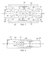
- FIG. 7 an orthogonal top view of an anchor 122 and a complementary connector 124 are shown in an assembled state according to another embodiment of the disclosure.
- the anchor 122 comprises a root rod 125 and the connector 124 comprises a tip rod 130.
- each of the root rod 125 and the tip rod 130 comprise recesses 126.
- side jaws 132 extend spanwise across the mating interface 112 and comprise teeth 134 on opposing spanwise sides of the side jaws 132 relative to the mating interface 112.
- side jaws 132 may be connected so at their top or bottom sides to generally form a C or U-shaped structure comprising the teeth 134.
- any substantial centrifugal force tending to pull the tip 110 away from the root 108 may be transferred from the recesses 126 associated with the tip rod 130 to the teeth 134 associated with the tip rod 130, from the teeth 134 associated with the tip rod 130 to the teeth associated with the root rod 125, and from the teeth 134 associated with the root rod 125 to the recesses 126 associated with the root rod 125. Because the anchor surfaces 128 are acutely angled relative to the spanwise axis 106 and the source of tension the side jaws 132 will not tend to move away from the root rod 125 and/or the tip rod 130.
- the side jaws 132 may be biased toward each other about a jaw pin through the use of a spring and/or any other suitable mechanical biasing device. Additionally and/or alternatively, the side jaws 132 may be at least one of biased toward each other and/or spatially restrained relative to the root rod 125 by disposing a plug 127, spacer, shim, epoxy, and/or any other suitably stiff and/or expansive material between the side jaws 132 and adjacent interior walls of the root cavity 118 and/or tip cavity 120. The side jaws 132 may be placed into position before a wall of the root cavity 118 and/or tip cavity 120 are fully formed. After such placement, a remainder of the root cavity 118 and/or tip cavity 120 may be completed to form the rotor blade 104.
- an orthogonal top view of an anchor 122 and a complementary connector 124 are shown in an assembled state according to another embodiment of the disclosure.
- the anchor 122 comprises an eccentric stud 150 and the connector 124 comprises a tension-torsion strap 152.
- the tension-torsion strap 152 may be placed around the eccentric stud 150 to provide a force path for centrifugal forces. In some cases, the tension-torsion strap 152 may not immediately be tightly mated against the eccentric stud 150. Accordingly, in some embodiments, the eccentric stud 150 may be rotated to tighten the eccentric stud 150 against the tension-torsion strap 152.
- the two may be spatially restrained relative to each other by disposing a plug 127, spacer, shim, epoxy, and/or any other suitably stiff and/or expansive material between interior of the tension-torsion strap 152 and the exterior of the eccentric stud 150. Further, additional plugs, spacers, shims, epoxy, and/or any other suitably stiff and/or expansive materials may be placed between the interior walls of the root cavity 118 and/or tip cavity 120 and the remainder of the tension-torsion strap 152 and/or eccentric stud 150.
- the rotor blade 104 comprises an access hole 900 formed in the root 108 that allows convenient access to at least one of the anchor 122 and the connector 124.
- a cover may be attached to the root 108 to cover the access hole 900 through the use of fasteners and/or fastener receivers 902.
- blade balancing weights 904 may also be accessible through the access hole 900.
- a tip may be removably connected to a root without utilizing one or more of a bolt, bonding a primary load path structure, a threaded connection between the tip and the root, and/or disposing elastomeric material between substantially rigid connection interfaces between the tip and the root.
- an anchor and a complementary connector may comprise undulating profiles and one or both of the anchor and the complementary connector may comprise elastic properties that allow insertion of the complementary connector into the anchor and may depend primarily on an interference fit and/or contact surface area dependent function for retaining the tip to the root during rotation of the rotor blade.
- R R l +k*(R u -R l ), wherein k is a variable ranging from 1 percent to 100 percent with a 1 percent increment, i.e., k is 1 percent, 2 percent, 3 percent, 4 percent, 5 percent, ..., 50 percent, 51 percent, 52 percent, ..., 95 percent, 96 percent, 97 percent, 98 percent, 99 percent, or 100 percent. Unless otherwise stated, the term "about” shall mean plus or minus 10 percent of the subsequent value.
- any numerical range defined by two R numbers as defined in the above is also specifically disclosed.
- Use of the term “optionally” with respect to any element of a claim means that the element is required, or alternatively, the element is not required, both alternatives being within the scope of the claim.
- Use of broader terms such as comprises, includes, and having should be understood to provide support for narrower terms such as consisting of, consisting essentially of, and comprised substantially of. Accordingly, the scope of protection is not limited by the description set out above but is defined by the claims that follow.
Landscapes
- Engineering & Computer Science (AREA)
- Mechanical Engineering (AREA)
- Aviation & Aerospace Engineering (AREA)
- Architecture (AREA)
- General Engineering & Computer Science (AREA)
- Turbine Rotor Nozzle Sealing (AREA)
Claims (15)
- Rotorblatt (104), umfassend:eine Spannweitenachse (106);einen Fuß (108), der einen Anker (122) mit einer Ankerfläche (128) umfasst, die zum Bilden mindestens eines normalen Winkels bezüglich der Spannweitenachse (106) und eines spitzen Winkels bezüglich der Spannweitenachse (106) konfiguriert ist; undeine selektiv entfernbare Spitze (110), die einen Verbinder (124) mit einer Verbinderfläche umfasst, die so konfiguriert ist, dass sie komplementär zur Ankerfläche (128) ist; dadurch gekennzeichnet, dass der Anker (122) und der Verbinder (124) so konfiguriert sind, dass Zusammenfügen der Ankerfläche (128) und der Verbinderfläche mindestens einen Teil sowohl des Ankers (122) als auch des Verbinders (124) in einen Fußhohlraum (118) des Fußes (108) anordnet.
- Verfahren zum Zusammenbau eines Rotorblatts (104), umfassend:Bereitstellen eines Fußes (108) entlang einer Spannweitenachse (106) und eines Ankers (122) mit einer Ankerfläche (128), die zum Bilden mindestens eines normalen Winkels bezüglich der Spannweitenachse (106) und eines spitzen Winkels bezüglich der Spannweitenachse (106) konfiguriert ist;Bereitstellen einer selektiv entfernbaren Spitze (110), die einen Verbinder (124) mit einer Verbinderfläche umfasst, die so konfiguriert ist, dass sie allgemein komplementär zur Ankerfläche (128) ist; undZusammenfügen der Verbinderfläche mit der Ankerfläche (128);wobei der Anker (122) und der Verbinder (124) so konfiguriert sind, dass Zusammenfügen der Ankerfläche (128) und der Verbinderfläche mindestens einen Teil sowohl des Ankers (122) als auch des Verbinders (124) in einen Fußhohlraum (118) des Fußes (108) anordnet.
- Rotorsystem (100), umfassend:eine Drehachse (102); undein Rotorblatt (104) nach Anspruch 1, wobei das Blatt (104) zur selektiven Drehung um die Drehachse (102) konfiguriert ist,wobei der Fuß (108) zumindest teilweise entlang der Spannweitenachse (106) zwischen der Spitze (110) und der Drehachse (102) angeordnet ist und mindestens ein Teil des Verbinders (124) entlang der Spannweitenachse (106) zwischen der Drehachse (102) und dem Anker (122) positioniert ist.
- Rotorblatt (104) nach Anspruch 1, wobei der Fuß (108) eine freitragende Fußstange (125) umfasst.
- Rotorblatt (104) nach Anspruch 1 oder Rotorblatt nach Anspruch 4, wobei eine Aussparung (126) des Ankers (122) die Ankerfläche (128) umfasst.
- Rotorblatt (104) nach Anspruch 5, wobei die Aussparung (126) eine allgemein dreieckige Gestalt oder eine allgemein rechteckige Gestalt umfasst.
- Rotorblatt (104) nach einem vorhergehenden Rotorblattanspruch, wobei der Verbinder (124) ein Paar einander gegenüberliegender Backen (132) umfasst.
- Rotorblatt (104) nach Anspruch 1 oder Rotorblatt (104) nach einem der Ansprüche 4 bis 7, wobei der Verbinder (124) einen Zahn (134) umfasst, der die Verbinderfläche umfasst, und wobei der Zahn (134) zu einer Aussparung (126) der Fußstange (125) vorgespannt ist.
- Rotorblatt (104) nach Anspruch 1 oder Rotorblatt (104) nach einem der Ansprüche 4 bis 7, wobei der Verbinder (124) ein Torsions-Spannungs-Band (152) und/oder einen Zahn (134) umfasst.
- Verfahren nach Anspruch 2, wobei mindestens ein Teil des Verbinders (124) vor dem Zusammenfügen in den Fußhohlraum (118) eingeführt wird.
- Verfahren nach Anspruch 2, wobei das Zusammenfügen vor dem Bilden des Fußhohlraums (118) des Fußes (108), der zur Aufnahme mindestens eines Teils sowohl des Ankers (122) als auch des Verbinders (124) konfiguriert ist, durchgeführt wird.
- Verfahren nach Anspruch 2, ferner umfassend: Vorspannen der Verbinderfläche mit der Ankerfläche (128) und/oder Einschränken der von der Verbinderfläche weg verlaufenden Bewegung der Ankerfläche (128).
- Verfahren nach Anspruch 2, wobei eine Kraft, mit der die Verbinderfläche und die Ankerfläche (128) zusammengefügt sind, mit einer sich aus der Drehung des Rotorblatts (104) um eine Drehachse (102) ergebenden Zunahme der Zentrifugalkraft zunimmt.
- Rotorsystem (100) nach Anspruch 3, wobei der Verbinder (124) ein Paar einander gegenüberliegender Backen (132) umfasst, die dazu konfiguriert sind, mit einer sich aus der Drehung des Rotorblatts (104) um die Drehachse (102) ergebenden Zunahme der Zentrifugalkraft mit zunehmender Kraft zueinander vorgespannt zu werden.
- Rotorsystem (100) nach Anspruch 3 oder Rotorsystem (100) nach Anspruch 14, wobei:der Verbinder (124) einen zu einer Aussparung (126) des Ankers (122) vorgespannten Zahn (134) umfasst; und/oderder Verbinder (124) dazu konfiguriert ist, in Eingriff mit dem Anker (122) zu gleiten.
Applications Claiming Priority (1)
| Application Number | Priority Date | Filing Date | Title |
|---|---|---|---|
| US13/789,265 US11261735B2 (en) | 2013-03-07 | 2013-03-07 | Removable rotor blade tip |
Publications (2)
| Publication Number | Publication Date |
|---|---|
| EP2774847A1 EP2774847A1 (de) | 2014-09-10 |
| EP2774847B1 true EP2774847B1 (de) | 2016-09-14 |
Family
ID=48190750
Family Applications (1)
| Application Number | Title | Priority Date | Filing Date |
|---|---|---|---|
| EP13165390.9A Active EP2774847B1 (de) | 2013-03-07 | 2013-04-25 | Abnehmbare Rotorschaufelspitze |
Country Status (3)
| Country | Link |
|---|---|
| US (1) | US11261735B2 (de) |
| EP (1) | EP2774847B1 (de) |
| CA (1) | CA2845134C (de) |
Families Citing this family (7)
| Publication number | Priority date | Publication date | Assignee | Title |
|---|---|---|---|---|
| US12365453B2 (en) | 2018-10-12 | 2025-07-22 | Textron Innovations Inc. | Multi-material ducted rotor blade tip extension |
| US11286037B2 (en) * | 2018-10-12 | 2022-03-29 | Textron Innovations Inc. | Ducted rotor blade tip extension |
| US11286036B2 (en) * | 2018-10-12 | 2022-03-29 | Textron Innovations Inc. | Ducted rotor blade tip extension |
| US10988243B2 (en) * | 2019-03-15 | 2021-04-27 | Bell Textron Inc. | Tension-torsion strap |
| US11498671B2 (en) | 2019-05-13 | 2022-11-15 | Lockheed Martin Corporation | Replacement tip section for a rotor blade and method of replacing a rotor blade tip section |
| US11565799B2 (en) | 2020-06-12 | 2023-01-31 | Textron Innovations Inc. | Adjustable ducted rotor blade tip extension |
| CN114486148A (zh) * | 2021-12-14 | 2022-05-13 | 西南科技大学 | 一种适用于桨尖涡流动控制实验研究的旋翼 |
Family Cites Families (22)
| Publication number | Priority date | Publication date | Assignee | Title |
|---|---|---|---|---|
| US1382849A (en) * | 1921-06-28 | Albert henry franks perl | ||
| US1878816A (en) * | 1925-12-30 | 1932-09-20 | Herbert E Bucklen Corp | Impeller |
| DE638559C (de) | 1933-08-11 | 1936-11-17 | D Aviat Louis Breguet Sa Des A | Hubschrauber mit gelenkig unterteilten steuerbaren Fluegeln |
| GB485750A (en) | 1936-08-24 | 1938-05-24 | Jean Louis Ambroise Castelli | Towing and dropping bombs and other articles from aircraft |
| US2118361A (en) * | 1936-12-09 | 1938-05-24 | Jr Ethan A Schaeffer | Quick action nut |
| US2257327A (en) * | 1941-04-23 | 1941-09-30 | Carios L Bradford | Nut |
| US2397132A (en) | 1943-03-20 | 1946-03-26 | Jr Frederick R Dent | Antiflutter and vibration device for fan and propeller blades |
| US2815820A (en) | 1955-04-19 | 1957-12-10 | Gyrodyne Company Of America In | Power folding rotor blade system for rotary wing aircraft |
| US5263821A (en) * | 1991-01-15 | 1993-11-23 | United Technologies Corporation | Mid-beam jointed reconfigurable bearingless main rotor assembly |
| US5320494A (en) * | 1992-12-22 | 1994-06-14 | United Technologies Corporation | Helicopter rotor blade having a replaceable anhedral tip |
| US5885059A (en) | 1996-12-23 | 1999-03-23 | Sikorsky Aircraft Corporation | Composite tip cap assembly for a helicopter main rotor blade |
| US6976829B2 (en) | 2003-07-16 | 2005-12-20 | Sikorsky Aircraft Corporation | Rotor blade tip section |
| EP1584817A1 (de) * | 2004-04-07 | 2005-10-12 | Gamesa Eolica, S.A. (Sociedad Unipersonal) | Windturbinenblatt |
| US7246998B2 (en) | 2004-11-18 | 2007-07-24 | Sikorsky Aircraft Corporation | Mission replaceable rotor blade tip section |
| US7762785B2 (en) * | 2007-12-10 | 2010-07-27 | Sikorsky Aircraft Corporation | Main rotor blade with integral tip section |
| ATE535709T1 (de) * | 2008-05-23 | 2011-12-15 | Siemens Ag | Spitzenendenhalter |
| WO2010023299A2 (en) * | 2008-08-31 | 2010-03-04 | Vestas Wind Systems A/S | A sectional blade |
| JP5249684B2 (ja) * | 2008-09-04 | 2013-07-31 | 三菱重工業株式会社 | 風車翼 |
| JP5326530B2 (ja) * | 2008-12-03 | 2013-10-30 | パナソニック株式会社 | ねじ部品及び撮像装置 |
| FR2948154B1 (fr) * | 2009-07-16 | 2011-09-16 | Astrium Sas | Dispositif d'assemblage de troncons de pales d'eoliennes et procede de liaison de troncons de pales d'eoliennes |
| GB201002249D0 (en) * | 2010-02-10 | 2010-03-31 | Walters Albert E D | Improvements in or relating to methods of manufacture |
| US9651024B2 (en) * | 2014-04-14 | 2017-05-16 | General Electric Company | Rotor blade assembly having internal loading features |
-
2013
- 2013-03-07 US US13/789,265 patent/US11261735B2/en active Active
- 2013-04-25 EP EP13165390.9A patent/EP2774847B1/de active Active
-
2014
- 2014-03-06 CA CA2845134A patent/CA2845134C/en active Active
Also Published As
| Publication number | Publication date |
|---|---|
| EP2774847A1 (de) | 2014-09-10 |
| US20140255201A1 (en) | 2014-09-11 |
| CA2845134C (en) | 2016-10-11 |
| US11261735B2 (en) | 2022-03-01 |
| CA2845134A1 (en) | 2014-09-07 |
Similar Documents
| Publication | Publication Date | Title |
|---|---|---|
| CA2845134C (en) | Removable rotor blade tip | |
| CA1321378C (fr) | Tete de rotor de giravion a tirants interpales de rappel elastique avec amortissement incorpore | |
| EP2374999B1 (de) | Turbinenschaufelbaugruppe aus Verbundwerkstoff | |
| EP2684799B1 (de) | Rotor eines Drehflügelflugzeugs, der mit Luftwiderstandsdämpfern ausgestattet ist, die sich in den Verbindungsmuffen der einnabigen Rotorblätter befinden | |
| CN102536331B (zh) | 结合了阻尼器和密封销的涡轮机叶片及其相关方法 | |
| EP2711293B1 (de) | Gehäuse mit einstellbarer Nutzlast für Flügel | |
| EP0214875B1 (de) | Dämpfungselement zur Begrenzung der Auslenkung von Rotorschaufeln einer Turbomaschine | |
| EP2532880B1 (de) | Rotorblatt für eine Windturbine | |
| EP2990882B1 (de) | Unruh mit Trägheitsregulierung | |
| US4579494A (en) | Flexible locking pin | |
| US9994311B2 (en) | Constant-velocity joint link with reduced axial stiffness | |
| JP5393294B2 (ja) | タービン動翼と、タービン動翼を固定したタービンロータ | |
| CA2807913A1 (fr) | Procede d'accrochage de blindage sur carter de turbine et ensemble d'accrochage pour sa mise en oeuvre | |
| EP0213016A1 (de) | Mast-Nabeneinheit und Drehflügerrotorkopf mit einer solchen Einheit | |
| KR20180054652A (ko) | 리벳 베인 레버의 토크 용량을 증대시키기 위한 지오메트리 | |
| KR20120088579A (ko) | 블레이드 및 블레이드의 제조 방법 | |
| CA2480234C (fr) | Procede permettant d'eviter les vibrations d'une gouverne de direction d'un aeronef et aeronef mettant en oeuvre ce procede | |
| EP3315403B1 (de) | Flexibles torsionsbündel für ein blatt, eine anordnung von flexiblen torsionsbündeln, ein rotor und ein luftfahrzeug | |
| CA2520778A1 (en) | Helicopter rotor | |
| FR3094347A1 (fr) | Attache moteur arrière d’un aéronef présentant des manilles en deux parties et aéronef comprenant au moins une telle attache moteur arrière | |
| FR2758524A1 (fr) | Rotor a pales multiples pour aeronef a voilure tournante | |
| EP2563651A1 (de) | Aufbau eines flugzeugrumpfes mit einer energiedämpfenden vorrichtung | |
| MX2021005133A (es) | Estructuras adaptables para aspas de rotor articuladas. | |
| US10330112B2 (en) | Fan blade with root through holes | |
| US20160167779A1 (en) | Laminated ball joint connection device between a rotorcraft rotor blade and a lead/lag damper of said blade |
Legal Events
| Date | Code | Title | Description |
|---|---|---|---|
| PUAI | Public reference made under article 153(3) epc to a published international application that has entered the european phase |
Free format text: ORIGINAL CODE: 0009012 |
|
| 17P | Request for examination filed |
Effective date: 20130425 |
|
| AK | Designated contracting states |
Kind code of ref document: A1 Designated state(s): AL AT BE BG CH CY CZ DE DK EE ES FI FR GB GR HR HU IE IS IT LI LT LU LV MC MK MT NL NO PL PT RO RS SE SI SK SM TR |
|
| AX | Request for extension of the european patent |
Extension state: BA ME |
|
| GRAP | Despatch of communication of intention to grant a patent |
Free format text: ORIGINAL CODE: EPIDOSNIGR1 |
|
| INTG | Intention to grant announced |
Effective date: 20160407 |
|
| GRAS | Grant fee paid |
Free format text: ORIGINAL CODE: EPIDOSNIGR3 |
|
| GRAA | (expected) grant |
Free format text: ORIGINAL CODE: 0009210 |
|
| AK | Designated contracting states |
Kind code of ref document: B1 Designated state(s): AL AT BE BG CH CY CZ DE DK EE ES FI FR GB GR HR HU IE IS IT LI LT LU LV MC MK MT NL NO PL PT RO RS SE SI SK SM TR |
|
| REG | Reference to a national code |
Ref country code: GB Ref legal event code: FG4D |
|
| REG | Reference to a national code |
Ref country code: CH Ref legal event code: EP |
|
| REG | Reference to a national code |
Ref country code: IE Ref legal event code: FG4D |
|
| REG | Reference to a national code |
Ref country code: AT Ref legal event code: REF Ref document number: 828654 Country of ref document: AT Kind code of ref document: T Effective date: 20161015 |
|
| REG | Reference to a national code |
Ref country code: DE Ref legal event code: R096 Ref document number: 602013011340 Country of ref document: DE |
|
| REG | Reference to a national code |
Ref country code: LT Ref legal event code: MG4D |
|
| REG | Reference to a national code |
Ref country code: NL Ref legal event code: MP Effective date: 20160914 |
|
| PG25 | Lapsed in a contracting state [announced via postgrant information from national office to epo] |
Ref country code: HR Free format text: LAPSE BECAUSE OF FAILURE TO SUBMIT A TRANSLATION OF THE DESCRIPTION OR TO PAY THE FEE WITHIN THE PRESCRIBED TIME-LIMIT Effective date: 20160914 Ref country code: RS Free format text: LAPSE BECAUSE OF FAILURE TO SUBMIT A TRANSLATION OF THE DESCRIPTION OR TO PAY THE FEE WITHIN THE PRESCRIBED TIME-LIMIT Effective date: 20160914 Ref country code: LT Free format text: LAPSE BECAUSE OF FAILURE TO SUBMIT A TRANSLATION OF THE DESCRIPTION OR TO PAY THE FEE WITHIN THE PRESCRIBED TIME-LIMIT Effective date: 20160914 Ref country code: FI Free format text: LAPSE BECAUSE OF FAILURE TO SUBMIT A TRANSLATION OF THE DESCRIPTION OR TO PAY THE FEE WITHIN THE PRESCRIBED TIME-LIMIT Effective date: 20160914 Ref country code: NO Free format text: LAPSE BECAUSE OF FAILURE TO SUBMIT A TRANSLATION OF THE DESCRIPTION OR TO PAY THE FEE WITHIN THE PRESCRIBED TIME-LIMIT Effective date: 20161214 |
|
| REG | Reference to a national code |
Ref country code: AT Ref legal event code: MK05 Ref document number: 828654 Country of ref document: AT Kind code of ref document: T Effective date: 20160914 |
|
| PG25 | Lapsed in a contracting state [announced via postgrant information from national office to epo] |
Ref country code: LV Free format text: LAPSE BECAUSE OF FAILURE TO SUBMIT A TRANSLATION OF THE DESCRIPTION OR TO PAY THE FEE WITHIN THE PRESCRIBED TIME-LIMIT Effective date: 20160914 Ref country code: SE Free format text: LAPSE BECAUSE OF FAILURE TO SUBMIT A TRANSLATION OF THE DESCRIPTION OR TO PAY THE FEE WITHIN THE PRESCRIBED TIME-LIMIT Effective date: 20160914 Ref country code: NL Free format text: LAPSE BECAUSE OF FAILURE TO SUBMIT A TRANSLATION OF THE DESCRIPTION OR TO PAY THE FEE WITHIN THE PRESCRIBED TIME-LIMIT Effective date: 20160914 Ref country code: GR Free format text: LAPSE BECAUSE OF FAILURE TO SUBMIT A TRANSLATION OF THE DESCRIPTION OR TO PAY THE FEE WITHIN THE PRESCRIBED TIME-LIMIT Effective date: 20161215 |
|
| REG | Reference to a national code |
Ref country code: FR Ref legal event code: PLFP Year of fee payment: 5 |
|
| PG25 | Lapsed in a contracting state [announced via postgrant information from national office to epo] |
Ref country code: EE Free format text: LAPSE BECAUSE OF FAILURE TO SUBMIT A TRANSLATION OF THE DESCRIPTION OR TO PAY THE FEE WITHIN THE PRESCRIBED TIME-LIMIT Effective date: 20160914 Ref country code: RO Free format text: LAPSE BECAUSE OF FAILURE TO SUBMIT A TRANSLATION OF THE DESCRIPTION OR TO PAY THE FEE WITHIN THE PRESCRIBED TIME-LIMIT Effective date: 20160914 |
|
| PG25 | Lapsed in a contracting state [announced via postgrant information from national office to epo] |
Ref country code: SK Free format text: LAPSE BECAUSE OF FAILURE TO SUBMIT A TRANSLATION OF THE DESCRIPTION OR TO PAY THE FEE WITHIN THE PRESCRIBED TIME-LIMIT Effective date: 20160914 Ref country code: SM Free format text: LAPSE BECAUSE OF FAILURE TO SUBMIT A TRANSLATION OF THE DESCRIPTION OR TO PAY THE FEE WITHIN THE PRESCRIBED TIME-LIMIT Effective date: 20160914 Ref country code: PT Free format text: LAPSE BECAUSE OF FAILURE TO SUBMIT A TRANSLATION OF THE DESCRIPTION OR TO PAY THE FEE WITHIN THE PRESCRIBED TIME-LIMIT Effective date: 20170116 Ref country code: CZ Free format text: LAPSE BECAUSE OF FAILURE TO SUBMIT A TRANSLATION OF THE DESCRIPTION OR TO PAY THE FEE WITHIN THE PRESCRIBED TIME-LIMIT Effective date: 20160914 Ref country code: AT Free format text: LAPSE BECAUSE OF FAILURE TO SUBMIT A TRANSLATION OF THE DESCRIPTION OR TO PAY THE FEE WITHIN THE PRESCRIBED TIME-LIMIT Effective date: 20160914 Ref country code: BE Free format text: LAPSE BECAUSE OF FAILURE TO SUBMIT A TRANSLATION OF THE DESCRIPTION OR TO PAY THE FEE WITHIN THE PRESCRIBED TIME-LIMIT Effective date: 20160914 Ref country code: IS Free format text: LAPSE BECAUSE OF FAILURE TO SUBMIT A TRANSLATION OF THE DESCRIPTION OR TO PAY THE FEE WITHIN THE PRESCRIBED TIME-LIMIT Effective date: 20170114 Ref country code: BG Free format text: LAPSE BECAUSE OF FAILURE TO SUBMIT A TRANSLATION OF THE DESCRIPTION OR TO PAY THE FEE WITHIN THE PRESCRIBED TIME-LIMIT Effective date: 20161214 Ref country code: PL Free format text: LAPSE BECAUSE OF FAILURE TO SUBMIT A TRANSLATION OF THE DESCRIPTION OR TO PAY THE FEE WITHIN THE PRESCRIBED TIME-LIMIT Effective date: 20160914 Ref country code: ES Free format text: LAPSE BECAUSE OF FAILURE TO SUBMIT A TRANSLATION OF THE DESCRIPTION OR TO PAY THE FEE WITHIN THE PRESCRIBED TIME-LIMIT Effective date: 20160914 |
|
| REG | Reference to a national code |
Ref country code: DE Ref legal event code: R097 Ref document number: 602013011340 Country of ref document: DE |
|
| PLBE | No opposition filed within time limit |
Free format text: ORIGINAL CODE: 0009261 |
|
| STAA | Information on the status of an ep patent application or granted ep patent |
Free format text: STATUS: NO OPPOSITION FILED WITHIN TIME LIMIT |
|
| PG25 | Lapsed in a contracting state [announced via postgrant information from national office to epo] |
Ref country code: DK Free format text: LAPSE BECAUSE OF FAILURE TO SUBMIT A TRANSLATION OF THE DESCRIPTION OR TO PAY THE FEE WITHIN THE PRESCRIBED TIME-LIMIT Effective date: 20160914 |
|
| 26N | No opposition filed |
Effective date: 20170615 |
|
| PG25 | Lapsed in a contracting state [announced via postgrant information from national office to epo] |
Ref country code: SI Free format text: LAPSE BECAUSE OF FAILURE TO SUBMIT A TRANSLATION OF THE DESCRIPTION OR TO PAY THE FEE WITHIN THE PRESCRIBED TIME-LIMIT Effective date: 20160914 |
|
| REG | Reference to a national code |
Ref country code: CH Ref legal event code: PL |
|
| REG | Reference to a national code |
Ref country code: IE Ref legal event code: MM4A |
|
| PG25 | Lapsed in a contracting state [announced via postgrant information from national office to epo] |
Ref country code: MC Free format text: LAPSE BECAUSE OF FAILURE TO SUBMIT A TRANSLATION OF THE DESCRIPTION OR TO PAY THE FEE WITHIN THE PRESCRIBED TIME-LIMIT Effective date: 20160914 |
|
| PG25 | Lapsed in a contracting state [announced via postgrant information from national office to epo] |
Ref country code: CH Free format text: LAPSE BECAUSE OF NON-PAYMENT OF DUE FEES Effective date: 20170430 Ref country code: LI Free format text: LAPSE BECAUSE OF NON-PAYMENT OF DUE FEES Effective date: 20170430 Ref country code: LU Free format text: LAPSE BECAUSE OF NON-PAYMENT OF DUE FEES Effective date: 20170425 |
|
| REG | Reference to a national code |
Ref country code: FR Ref legal event code: PLFP Year of fee payment: 6 |
|
| PG25 | Lapsed in a contracting state [announced via postgrant information from national office to epo] |
Ref country code: IE Free format text: LAPSE BECAUSE OF NON-PAYMENT OF DUE FEES Effective date: 20170425 |
|
| PG25 | Lapsed in a contracting state [announced via postgrant information from national office to epo] |
Ref country code: MT Free format text: LAPSE BECAUSE OF NON-PAYMENT OF DUE FEES Effective date: 20170425 |
|
| PG25 | Lapsed in a contracting state [announced via postgrant information from national office to epo] |
Ref country code: AL Free format text: LAPSE BECAUSE OF FAILURE TO SUBMIT A TRANSLATION OF THE DESCRIPTION OR TO PAY THE FEE WITHIN THE PRESCRIBED TIME-LIMIT Effective date: 20160914 |
|
| PG25 | Lapsed in a contracting state [announced via postgrant information from national office to epo] |
Ref country code: HU Free format text: LAPSE BECAUSE OF FAILURE TO SUBMIT A TRANSLATION OF THE DESCRIPTION OR TO PAY THE FEE WITHIN THE PRESCRIBED TIME-LIMIT; INVALID AB INITIO Effective date: 20130425 |
|
| PG25 | Lapsed in a contracting state [announced via postgrant information from national office to epo] |
Ref country code: CY Free format text: LAPSE BECAUSE OF FAILURE TO SUBMIT A TRANSLATION OF THE DESCRIPTION OR TO PAY THE FEE WITHIN THE PRESCRIBED TIME-LIMIT Effective date: 20160914 |
|
| PG25 | Lapsed in a contracting state [announced via postgrant information from national office to epo] |
Ref country code: MK Free format text: LAPSE BECAUSE OF FAILURE TO SUBMIT A TRANSLATION OF THE DESCRIPTION OR TO PAY THE FEE WITHIN THE PRESCRIBED TIME-LIMIT Effective date: 20160914 |
|
| PG25 | Lapsed in a contracting state [announced via postgrant information from national office to epo] |
Ref country code: TR Free format text: LAPSE BECAUSE OF FAILURE TO SUBMIT A TRANSLATION OF THE DESCRIPTION OR TO PAY THE FEE WITHIN THE PRESCRIBED TIME-LIMIT Effective date: 20160914 |
|
| P01 | Opt-out of the competence of the unified patent court (upc) registered |
Effective date: 20230602 |
|
| PGFP | Annual fee paid to national office [announced via postgrant information from national office to epo] |
Ref country code: DE Payment date: 20250429 Year of fee payment: 13 |
|
| PGFP | Annual fee paid to national office [announced via postgrant information from national office to epo] |
Ref country code: GB Payment date: 20250428 Year of fee payment: 13 |
|
| PGFP | Annual fee paid to national office [announced via postgrant information from national office to epo] |
Ref country code: IT Payment date: 20250422 Year of fee payment: 13 |
|
| PGFP | Annual fee paid to national office [announced via postgrant information from national office to epo] |
Ref country code: FR Payment date: 20250425 Year of fee payment: 13 |